EP2796256A2 - Rotationsstanze - Google Patents
Rotationsstanze Download PDFInfo
- Publication number
- EP2796256A2 EP2796256A2 EP20140165941 EP14165941A EP2796256A2 EP 2796256 A2 EP2796256 A2 EP 2796256A2 EP 20140165941 EP20140165941 EP 20140165941 EP 14165941 A EP14165941 A EP 14165941A EP 2796256 A2 EP2796256 A2 EP 2796256A2
- Authority
- EP
- European Patent Office
- Prior art keywords
- sheet
- pair
- magnet
- rollers
- anvil
- Prior art date
- Legal status (The legal status is an assumption and is not a legal conclusion. Google has not performed a legal analysis and makes no representation as to the accuracy of the status listed.)
- Granted
Links
Images



Classifications
-
- B—PERFORMING OPERATIONS; TRANSPORTING
- B26—HAND CUTTING TOOLS; CUTTING; SEVERING
- B26F—PERFORATING; PUNCHING; CUTTING-OUT; STAMPING-OUT; SEVERING BY MEANS OTHER THAN CUTTING
- B26F1/00—Perforating; Punching; Cutting-out; Stamping-out; Apparatus therefor
- B26F1/38—Cutting-out; Stamping-out
- B26F1/384—Cutting-out; Stamping-out using rotating drums
-
- B—PERFORMING OPERATIONS; TRANSPORTING
- B26—HAND CUTTING TOOLS; CUTTING; SEVERING
- B26D—CUTTING; DETAILS COMMON TO MACHINES FOR PERFORATING, PUNCHING, CUTTING-OUT, STAMPING-OUT OR SEVERING
- B26D5/00—Arrangements for operating and controlling machines or devices for cutting, cutting-out, stamping-out, punching, perforating, or severing by means other than cutting
- B26D5/007—Control means comprising cameras, vision or image processing systems
-
- B—PERFORMING OPERATIONS; TRANSPORTING
- B26—HAND CUTTING TOOLS; CUTTING; SEVERING
- B26D—CUTTING; DETAILS COMMON TO MACHINES FOR PERFORATING, PUNCHING, CUTTING-OUT, STAMPING-OUT OR SEVERING
- B26D5/00—Arrangements for operating and controlling machines or devices for cutting, cutting-out, stamping-out, punching, perforating, or severing by means other than cutting
- B26D5/20—Arrangements for operating and controlling machines or devices for cutting, cutting-out, stamping-out, punching, perforating, or severing by means other than cutting with interrelated action between the cutting member and work feed
- B26D5/30—Arrangements for operating and controlling machines or devices for cutting, cutting-out, stamping-out, punching, perforating, or severing by means other than cutting with interrelated action between the cutting member and work feed having the cutting member controlled by scanning a record carrier
- B26D5/32—Arrangements for operating and controlling machines or devices for cutting, cutting-out, stamping-out, punching, perforating, or severing by means other than cutting with interrelated action between the cutting member and work feed having the cutting member controlled by scanning a record carrier with the record carrier formed by the work itself
-
- B—PERFORMING OPERATIONS; TRANSPORTING
- B65—CONVEYING; PACKING; STORING; HANDLING THIN OR FILAMENTARY MATERIAL
- B65H—HANDLING THIN OR FILAMENTARY MATERIAL, e.g. SHEETS, WEBS, CABLES
- B65H11/00—Feed tables
- B65H11/002—Feed tables incorporating transport belts
- B65H11/005—Suction belts
-
- B—PERFORMING OPERATIONS; TRANSPORTING
- B65—CONVEYING; PACKING; STORING; HANDLING THIN OR FILAMENTARY MATERIAL
- B65H—HANDLING THIN OR FILAMENTARY MATERIAL, e.g. SHEETS, WEBS, CABLES
- B65H5/00—Feeding articles separated from piles; Feeding articles to machines
- B65H5/06—Feeding articles separated from piles; Feeding articles to machines by rollers or balls, e.g. between rollers
- B65H5/062—Feeding articles separated from piles; Feeding articles to machines by rollers or balls, e.g. between rollers between rollers or balls
-
- B—PERFORMING OPERATIONS; TRANSPORTING
- B65—CONVEYING; PACKING; STORING; HANDLING THIN OR FILAMENTARY MATERIAL
- B65H—HANDLING THIN OR FILAMENTARY MATERIAL, e.g. SHEETS, WEBS, CABLES
- B65H7/00—Controlling article feeding, separating, pile-advancing, or associated apparatus, to take account of incorrect feeding, absence of articles, or presence of faulty articles
- B65H7/20—Controlling associated apparatus
-
- B—PERFORMING OPERATIONS; TRANSPORTING
- B26—HAND CUTTING TOOLS; CUTTING; SEVERING
- B26D—CUTTING; DETAILS COMMON TO MACHINES FOR PERFORATING, PUNCHING, CUTTING-OUT, STAMPING-OUT OR SEVERING
- B26D7/00—Details of apparatus for cutting, cutting-out, stamping-out, punching, perforating, or severing by means other than cutting
- B26D7/26—Means for mounting or adjusting the cutting member; Means for adjusting the stroke of the cutting member
- B26D2007/2607—Means for mounting or adjusting the cutting member; Means for adjusting the stroke of the cutting member for mounting die cutters
-
- B—PERFORMING OPERATIONS; TRANSPORTING
- B65—CONVEYING; PACKING; STORING; HANDLING THIN OR FILAMENTARY MATERIAL
- B65H—HANDLING THIN OR FILAMENTARY MATERIAL, e.g. SHEETS, WEBS, CABLES
- B65H2301/00—Handling processes for sheets or webs
- B65H2301/40—Type of handling process
- B65H2301/44—Moving, forwarding, guiding material
- B65H2301/449—Features of movement or transforming movement of handled material
- B65H2301/4493—Features of movement or transforming movement of handled material intermittent
-
- B—PERFORMING OPERATIONS; TRANSPORTING
- B65—CONVEYING; PACKING; STORING; HANDLING THIN OR FILAMENTARY MATERIAL
- B65H—HANDLING THIN OR FILAMENTARY MATERIAL, e.g. SHEETS, WEBS, CABLES
- B65H2513/00—Dynamic entities; Timing aspects
- B65H2513/40—Movement
-
- Y—GENERAL TAGGING OF NEW TECHNOLOGICAL DEVELOPMENTS; GENERAL TAGGING OF CROSS-SECTIONAL TECHNOLOGIES SPANNING OVER SEVERAL SECTIONS OF THE IPC; TECHNICAL SUBJECTS COVERED BY FORMER USPC CROSS-REFERENCE ART COLLECTIONS [XRACs] AND DIGESTS
- Y10—TECHNICAL SUBJECTS COVERED BY FORMER USPC
- Y10T—TECHNICAL SUBJECTS COVERED BY FORMER US CLASSIFICATION
- Y10T83/00—Cutting
- Y10T83/465—Cutting motion of tool has component in direction of moving work
- Y10T83/4766—Orbital motion of cutting blade
- Y10T83/4795—Rotary tool
- Y10T83/483—With cooperating rotary cutter or backup
- Y10T83/4838—With anvil backup
Definitions
- the present invention relates to a rotary die cutter comprises a pair of a magnet roller on which a flexible die is mounted, and an anvil roller arranged opposite to the magnet roller and punches out a sheet is supplied one by one between the magnet roller and the anvil roller.
- a conventional rotary die cutter comprises a magnet roller, an anvil roller arranged opposite to the magnet roller, a single flexible die mounted on the magnet roller and a sheet feed unit supplying a sheet one by one between the magnet and anvil rollers, in which the sheet supplied from the sheet feed unit is punched out by the flexible die (the term “punch” may be used to denote not only its original meanings but also “emboss”, “score”, “perforate” and so on. The same applies hereinafter.) while the sheet is conveyed by the magnet and anvil rollers (See, for example, JP 2003-237018 A and JP 2012-161859 A ).
- the largest possible size of the flexible die (the flexible die extending over the whole circumference of the magnet roller) is used. This configuration is quite effective in mass production of the same type of product.
- this conventional rotary die cutter has the disadvantages that a sheet needs to have a certain size adapted for the flexible die and the use of a small size of the flexible die causes reduction of a production volume per revolution of the magnet and anvil rollers.
- an object of the present invention to provide a rotary die cutter enable manufacturing of a wide variety of products in small quantities at low cost.
- a rotary die cutter comprising: a magnet roller; an anvil roller arranged in parallel with and opposite to the magnet roller with a gap therebetween; a single sheet-like flexible die mounted on the magnet roller; a pair of feed rollers spaced from the pair of magnet and anvil rollers; a first drive mechanism rotating the magnet and anvil rollers in such a way that the magnet and anvil rollers are constantly rotated synchronously with each other at an equal circumferential velocity, a second drive mechanism rotating the pair of feed rollers; a controller controlling the first and second drive mechanisms, the magnet and anvil rollers being rotated in a direction to receive a sheet from the pair of feed rollers; and a sensor arranged between the pair of magnet and anvil rollers and the pair of feed rollers to detect the passage of a leading end of the sheet, wherein every time a detection signal is outputted from the sensor, the pair of feed rollers is intermittently rotated in a direction to convey the sheet to the pair of
- punch may be used to denote not only its original meanings but also “emboss”, “score”, “perforate” and so on. The same applies hereinafter.
- the controller comprises an input unit for receiving input of the data about the punching of the sheet including a size of the sheet, a distance from the leading end of the sheet to a leading end of a punching range on the sheet, and a position of a start point of punching on the sheet at each punching operation of the flexible die, and the timing of rotation of the pair of feed rollers is determined by the controller based on the data about the punching of the sheet, the rotational velocity of the pair of feed rollers, and the peripheral velocity and the rotational position of the flexible die.
- the rotary die cutter further comprises: a sheet supply unit supplying sheets one by one from a sheet stack; and a suction conveyor belt extending between the sheet supply unit and the pair of feed rollers so as to convey the sheet from the sheet supply unit to the pair of feed rollers while the sheet is sucked by the suction conveyor belt at the underside thereof, wherein the sheet supply unit and the suction conveyor belt is controlled by the controller so that the suction conveyor belt constantly operates while the sheet supply unit supplies the next sheet every time the punching of the previous sheet is completed.
- the first drive mechanism rotating the magnet and anvil rollers and the second drive mechanism rotating the pair of feed rollers are arranged independently of each other so that the pair of magnet and anvil rollers does not contribute to conveying the sheet substantially but exclusively performs the punching operation of the sheet on the one hand and the pair of feed rollers conveys the sheet on the other hand, and thereby the punching of the sheet is performed while the sheet is conveyed by the pair of feed rollers between the magnet and anvil rollers. Consequently, the punching can be accurately done at the predetermined positions on the sheet independently of a size of the flexible die.
- the pair of feed rollers is intermittently rotated in the direction to convey the sheet to the pair of magnet and anvil rollers, or alternately rotated in the direction to convey the sheet to the pair of magnet and anvil rollers and the reverse direction at the predetermined timing so that the sheet is intermittently moved forward, or repeatedly moved forward and backward with respect to the pair of magnet and anvil rollers, and thereby the pair of magnet and anvil rollers can make two or more revolutions while the sheet passes through the pair of magnet and anvil rollers. Consequently, a length of the flexible die along a circumference of the magnet roller can be limited to the bare minimum, so that the cost of manufacturing the flexible die is considerably reduced when compared to the above-mentioned conventional rotary die cutter. Therefore, it is possible to achieve the manufacturing of a wide variety of products in small quantities at low cost.
- FIG. 1 is a side view schematically showing a configuration of a rotary die cutter according to an embodiment of the present invention
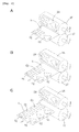
- Fig. 2A through 2C are perspective views illustrating an operation of the rotary die cutter shown in Fig. 1 , respectively.
- a rotary die cutter comprises a sheet supply unit 1 supplying sheets S one by one from a sheet stack P, a suction conveyor belt 2 arranged downstream of the sheet supply unit 1 to convey the sheet S received from the sheet supply unit 1, a punching unit 3 arranged downstream of the suction conveyor belt 2, an ejecting unit 4 arranged downstream of the punching unit 3 to eject the punched sheet S, and a controller 5 controlling operations of the sheet supply unit 1, the suction conveyor belt 2, the punching unit 3 and the ejecting unit 4.
- the suction conveyor belt 2 comprises a pair of horizontal roller 6, 7 arranged adjacent to the sheet supply unit 1 and the punching unit 3 and extending across and perpendicular to a sheet conveying path, and an endless belt 10 extending between the pair of rollers 6, 7. Vents are uniformly formed on the endless belt 10.
- One roller 6 of the pair of rollers 6, 7 is provided with a first pulley 8 at a shaft thereof and a motor 11 is arranged below the roller 6.
- a drive shaft of the motor 11 extends parallel to the roller 6 and is provided with a second pulley 12.
- An another endless belt 13 extends between the first and second pulleys 8, 12.
- the endless belt 10 is circulated by the motor 11.
- a suction duct 14 is arranged below an upper straight portion of the endless belt 10 between the pair of rollers 6, 7.
- the suction duct 14 is provided with intake vents at its upper surface and connected to a vacuum pump 15.
- the endless belt 10 circulates and the vacuum pump operates so that the sheet S supplied from the sheet supply unit 1 is conveyed to the punching unit 3 while the sheet S is sucked by the suction conveyor belt 10 at the underside thereof.
- the motor 11 and the vacuum pump 15 are controlled by the controller 5
- the punching unit 3 comprises a magnet roller 16 arranged parallel to the pair of rollers 6, 7, and an anvil roller 17 arranged in parallel with and opposite to the magnet roller 16 with a gap therebetween. As shown in Fig. 2 , a single sheet-like flexible die 29 is mounted on the magnet roller 6 by means of the magnet force of the magnet roller 6.
- the anvil roller 17 is provided with a third pulley 18 at a shaft thereof and a motor 19 is arranged below the anvil roller 17.
- a drive shaft of the motor 19 is provided with a fourth pulley 19a and extends parallel to the anvil roller 17.
- a first timing belt 20 extends between the third and fourth pulleys 18, 19a.
- the anvil roller 17 is rotated by the motor 19.
- the motor 19 is controlled by the controller 5.
- a shaft of the magnet roller 16 is coupled to the shaft of the anvil roller 17 through a connecting mechanism (not shown) in such a way that the magnet and anvil rollers 16, 17 are rotated synchronously with each other at an equal circumferential velocity in a direction to receive a sheet S from the suction conveyor belt 2.
- the motor 19, the third and fourth pulleys 18, 19a, the first timing belt 20 and the connecting mechanism construct a first drive mechanism rotating the magnet and anvil rollers 16, 17.
- a rotary encoder 22 is arranged between the anvil roller 17 and the motor 19.
- a rotary shaft of the rotary encoder 22 is provided with a fifth pulley 21 and extends parallel with the shaft of the anvil roller 17.
- the fifth pulley 21 contacts with the first timing belt 20 so as to be rotated by the circulation of the first timing belt 20.
- the control unit 5 detects a rotational position of the anvil roller 17, that is, the magnet roller 16 (that is, the flexible die 29) based on pulses outputted from the rotary encoder 22.
- the punching unit 3 further comprises a pair of feed rollers 23a, 23b spaced upstream of the pair of magnet and anvil rollers 16, 17 and arranged adjacent to the downstream of the suction conveyor belt 2.
- the pair of feed rollers 23a, 23b consists of a pair of rollers which are arranged opposite to each other in a vertical direction and extend parallel to the magnet and anvil rollers 16, 17.
- a lower roller 23b of the pair of feed rollers 23a, 23b is provided with a sixth pulley 24 at a shaft thereof.
- a servo motor 25 is arranged below the lower roller 23b, and a drive shaft of the servo motor 25 is provided with a seventh pulley 26 and extends parallel to the lower roller 23b.
- a second timing belt 27 extends between the sixth and seventh pulleys 24, 26 so that the pair of feed rollers 23a, 23b are rotated in clockwise and anticlockwise directions by the servo motor 25.
- the servo motor 25 is controlled by the control unit 5.
- the servo motor 25, the sixth and seventh pulleys 24, 26 and the second timing belt 27 construct a second drive mechanism rotating the pair of feed rollers 23a, 23b.
- a sensor 28 is arranged downstream of the pair of feed rollers 23a, 23b so as to detect the passage of a leading end of the sheet S. Detection signals are sent to the controller 5.
- a flat support plate 32 is arranged between the pair of feed rollers 23a, 23b and the pair of magnet and anvil rollers 16, 17 so as to support the underside of the sheet conveyed by the pair of feed rollers 23a, 23b.
- the support plate 32 is provided if needed.
- the controller 5 comprises an input unit for receiving input of the data about the punching of the sheet, for example, a size of the sheet S, a distance from the leading end of the sheet S to a leading end of a punching range on the sheet S, and a position of a start point of punching on the sheet S at each punching operation of the flexible die 28.
- the input unit is composed of a touch panel display 9 and a numerical key pad (not shown).
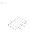
- Fig. 7 is a plan view showing an example of a data input screen displayed on the touch panel display 9.
- the data input screen shown in Fig. 7 corresponds to a situation in which the punching operation of the flexible die is performed three times for a single sheet so as to punch three areas spaced in a conveying direction of the sheet in the same pattern.
- a picture of a sheet is displayed in the center of the data input screen and data input columns 33-36 are provided to input the required data easily with the help of the picture.
- a size of the sheet in a lengthwise direction (the conveying direction of the sheet) is inputted in the data input column 33 and a size of the sheet in a crosswise direction (a direction perpendicular to the conveying direction) is inputted in the data input column 34.
- a distance from a leading end of the sheet to a leading end of a whole punching range on the sheet is inputted in the data input column 35 and a distance between the leading end of a first punching range on the sheet and the leading end of a second punching range on the sheet is inputted in the data input area 36 (in this embodiment, the punching operation is repeated at even intervals and therefore, only input of the distance between the leading end of the first punching range on the sheet and the leading end of the second punching range on the sheet is enough).
- the necessary numerical data is inputted in those data input columns 33-36 through the numerical key pad.
- the distance from the reading end of the sheet to the leading end of the whole punching range on the sheet and the distances between the leading ends of the adjacent punching ranges on the sheet can be inputted separately, for example, when a sheet is punched according to a pattern printed thereon, even though a shrink of the sheet due to printing causes misalignment of shapes of the printed pattern, correspondingly, it is possible to easily correct the position of punching.
- the sheet S supplied by the sheet supply unit 1 is conveyed by the suction conveyor belt 2 and fed in a gap between the pair of feed rollers 23a, 23b.
- the suction conveyor belt 2 constantly operates while the sheet supply unit 1 supplies the next sheet S every time the punching of the previous sheet S is completed.
- the operation of the suction conveyor belt 2 does not block the conveyance of the sheet S by the rotation of the pair of feed rollers 23a, 23b in the clockwise and anticlockwise directions.
- the sheet S fed in the gap between the pair of feed rollers 23a, 23b is conveyed to a gap between the magnet and anvil rollers 16, 17 by the pair of feed rollers 23a, 23b while being guided by the support plate 32.
- the pair of feed rollers 23a, 23b is intermittently rotated in a direction to convey the sheet S to the pair of magnet and anvil rollers 16, 17, or alternately rotated in the direction to convey the sheet S to the pair of the magnet and anvil rollers 16, 17 and the reverse direction at a predetermined timing corresponding to a peripheral velocity and a rotational position of the flexible die 29 (the rotation of the pair of feed rollers 23a, 23b in the direction to convey the sheet to the pair of magnet and anvil rollers 16, 16 will be referred as "forward rotation” and the rotation of the pair of feed rollers 23a, 23b in the reverse direction will be referred as "reverse rotation” hereinafter).
- the timing of rotation of the pair of feed rollers 23a, 23b is determined by the controller 5 based on the data about the punching of the sheet S, the data being inputted through the input unit, the rotational velocity of the pair of feed rollers 23a, 23b, and the peripheral velocity and the rotational position of the flexible die 29.
- the sheet S is intermittently advanced toward, or alternately advanced toward and retreated from the pair of magnet and anvil rollers 16, 17 so that, as shown in Fig. 2 , a plurality of areas G1-G3 spaced from each other in the conveying direction on the sheet S are punched by the flexible die 29.
- the pair of magnet and anvil rollers 16, 17 does not contribute to conveying the sheet S substantially but exclusively performs the punching operation of the sheet except when the flexible die cuts into the sheet S on the one hand and the pair of feed rollers conveys the sheet on the other hand.
- the ejecting unit 4 comprises a conveyor belt 30 extending from an exit of the pair of magnet and anvil rollers 16, 17 to an exit of the rotary die cutter, a feed roller 31 arranged adjacent to the downstream of the conveyor belt 30.
- the feed roller 31 extends perpendicularly to the conveyor belt 30 and contacts the upper surface of the conveyor belt 30.
- the sheet S punched by the punching unit 3 is conveyed by the conveyor belt 30 and the feed roller 31 and discharged from the exit of the rotary die cutter.
- the explanation is based on the assumption that the sheet S is punched by the flexible die 29 at three areas thereof spaced in the conveying direction.
- Fig. 3 is a graph indicating a change in a travelling distance of the leading end of the sheet S measured from the pair of feed rollers 23a, 23b against time after the sheet S is fed in the gap between the pair of feed rollers 23a, 23b in this operation mode.
- a curve X represents a sheet S and a curve Y represents the next sheet S.
- a vertical axis of the graph represents the travelling distance of the sheet S and a horizontal axis of the graph represents time.
- An alphabet L represents a length of the whole punching range on the sheet S
- each alphabet m1-m3 represents a length of each of first through third punching ranges
- an alphabet T represents a time required for the magnet roller 16 to make one revolution (rotation period).
- Fig. 4A through 4F are side views showing a positional relation of the pair of magnet and anvil rollers 16, 17 and the sheet S at points A through F on the graph shown in Fig. 3 , respectively.
- the sheet S is further advanced (conveyed toward the downstream between the magnet and anvil rollers 16, 17) at the same speed as the peripheral velocity of the pair of magnet and anvil rollers 16, 17.
- a first punching operation by the flexible die 19 is performed within the first punching range m1 on the sheet S.
- the pair of feed rollers 23a, 23b starts decelerating, and when the punched area G1 of the sheet is completely ejected from the pair of magnet and anvil rollers 16, 17, the pair of feed rollers 23a, 23b stops rotating (See, the point C in Fig. 3 and Fig. 4C ).
- the punching is performed by the flexible die 29 in the first punching range m1 on the sheet S during one revolution of the pair of magnet and anvil rollers 16, 17 (time T) (See, G1 of Figs. 2 and 4C ).
- the sheet S is retreated by the reverse rotation of the pair of feed rollers 23a, 23b (See, the point D in Fig. 3 and Fig. 4D ). Thereafter, when the leading end of the second punching range m2 on the sheet S arrives at a point separated by a predetermined distance on the upstream side of the pair of magnet and anvil rollers 16, 17, the pair of feed rollers 23a, 23b stop rotating (See, the point E in Fig. 3 and Fig. 4E ).
- the punching is performed by the flexible die 29 in the second punching range m2 on the sheet S during one revolution of the pair of magnet and anvil rollers 16, 17, and the punching is performed by the flexible die 29 in the third punching range m3 on the sheet S during further one revolution of the pair of magnet and anvil rollers 16, 17.
- the punching of the same pattern is performed at three areas G1-G3 of the sheet S spaced in the conveying direction.
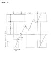
- Fig. 5 is a graph indicating a change in a travelling distance of the leading end of the sheet S measured from the pair of feed rollers 23a, 23b against time after the sheet S is fed in the gap between the pair of feed rollers 23a, 23b in this operation mode.
- a line X represents a sheet S and a line Y represents the next sheet S.
- a vertical axis of the graph represents the travelling distance of the sheet S and a horizontal axis of the graph represents time.
- An alphabet L represents a length of the whole punching range on the sheet S
- each alphabet m1-m3 represents a length of each of first through third punching ranges
- an alphabet T represents a time required for the magnet roller 16 to make one revolution (rotation period).
- Fig. 6A through 6D are side views showing a positional relation of the pair of magnet and anvil rollers 16, 17 and the sheet S at points A through D on the graph shown in Fig. 5 , respectively.
- the sheet S is further advanced (conveyed toward the downstream between the magnet and anvil rollers 16, 17) at the same speed as the peripheral velocity of the pair of magnet and anvil rollers 16, 17.
- a first punching operation by the flexible die 29 is performed within the first punching range m1 on the sheet S.
- the punching is performed by the flexible die 29 in the first punching range m1 on the sheet S during one revolution of the pair of magnet and anvil rollers 16, 17 (time T) (See, G1 of Figs. 2 and 6C ).
- the pair of feed rollers 23a, 23b starts the forward rotation right before the leading end of the flexible die 29 reaches the lowest point of the periphery of the magnet roller 16 again, so that the sheet S is advanced (conveyed toward the downstream between the magnet and anvil rollers 16, 17) at the same speed as the peripheral velocity of the pair of magnet and anvil rollers 16, 17.
- a second punching operation by the flexible die 29 is performed within the second punching range m2 on the sheet S (See, the point D in Fig. 5 and Fig. 6D ).
- the punching is performed by the flexible die 29 in the third punching range m3 on the sheet S during one revolution of the pair of magnet and anvil rollers 16, 17
- the punching of the same pattern is performed at three areas G1-G3 of the sheet S spaced in the conveying direction.
- the first drive mechanism rotating the magnet and anvil rollers 16, 17 and the second drive mechanism rotating the pair of feed rollers 23a, 23b are arranged independently of each other so that the pair of magnet and anvil rollers 16, 17 does not contribute to conveying the sheet S substantially but exclusively performs the punching operation of the sheet S on the one hand and the pair of feed rollers 23a, 23b conveys the sheet S on the other hand, and thereby the punching of the sheet S is performed while the sheet S is conveyed by the pair of feed rollers 23a, 23b between the magnet and anvil rollers 16, 17.
- the punching can be accurately done at the predetermined positions on the sheet S independently of a size of the flexible die 29.
- the pair of feed rollers 23a, 23b is intermittently rotated in the direction to convey the sheet S to the pair of magnet and anvil rollers 16, 17, or alternately rotated in the direction to convey the sheet S to the pair of magnet and anvil rollers 16, 17 and the reverse direction at the predetermined timing in such a way that the sheet S is intermittently moved forward, or repeatedly moved forward and backward with respect to the pair of magnet and anvil rollers 16, 17, and thereby the pair of magnet and anvil rollers 16, 17 can make two or more revolutions while the sheet S passes through the pair of magnet and anvil rollers 16, 17.
- a length of the flexible die 29 along a circumference of the magnet roller 16 can be limited to the bare minimum, so that the cost of manufacturing the flexible die 29 is considerably reduced when compared to the above-mentioned conventional rotary die cutter. Therefore, it is possible to achieve the manufacturing of a wide variety of products in small quantities at low cost.
- a servo motor is used in the first drive mechanism rotating the pair of feed rollers 23a, 23b and a general motor is used in the second drive mechanism rotating the pair of magnet and anvil rollers 16, 17 and a rotary encoder is used for detection of rotational position of the magnet roller 16 in the above-mentioned embodiments
- servo motors or stepping motors may be used in both of the first and second drive mechanisms.
- the punching of the same pattern is performed on the sheet S at regular intervals in the conveying direction in the above-mentioned embodiments
- the punching pattern of the same pattern may be performed a plurality of areas of the sheet randomly spaced in the conveying direction.
- lines of perforation L1-L3 may be formed on a plurality of areas of the sheet S spaced in the conveying direction by using a flexible die for making perforation as the flexible die 29.
- a scoring process may be performed on the sheet S by using a flexible die for scoring as the flexible die 29.
Landscapes
- Engineering & Computer Science (AREA)
- Mechanical Engineering (AREA)
- Life Sciences & Earth Sciences (AREA)
- Forests & Forestry (AREA)
- Computer Vision & Pattern Recognition (AREA)
- Perforating, Stamping-Out Or Severing By Means Other Than Cutting (AREA)
- Details Of Cutting Devices (AREA)
Applications Claiming Priority (2)
| Application Number | Priority Date | Filing Date | Title |
|---|---|---|---|
| JP2013093711 | 2013-04-26 | ||
| JP2014059951A JP5804582B2 (ja) | 2013-04-26 | 2014-03-24 | 回転式打抜機 |
Publications (3)
| Publication Number | Publication Date |
|---|---|
| EP2796256A2 true EP2796256A2 (de) | 2014-10-29 |
| EP2796256A3 EP2796256A3 (de) | 2014-11-26 |
| EP2796256B1 EP2796256B1 (de) | 2021-06-09 |
Family
ID=50542943
Family Applications (1)
| Application Number | Title | Priority Date | Filing Date |
|---|---|---|---|
| EP14165941.7A Active EP2796256B1 (de) | 2013-04-26 | 2014-04-25 | Verfahren zum Betreiben einer Rotationsstanze und Rotationsstanze |
Country Status (4)
| Country | Link |
|---|---|
| US (1) | US9522478B2 (de) |
| EP (1) | EP2796256B1 (de) |
| JP (1) | JP5804582B2 (de) |
| CN (1) | CN104118010B (de) |
Cited By (1)
| Publication number | Priority date | Publication date | Assignee | Title |
|---|---|---|---|---|
| EP4049818A4 (de) * | 2019-10-25 | 2023-08-02 | Horizon International Inc. | System zur bildung von indexlaschen |
Families Citing this family (14)
| Publication number | Priority date | Publication date | Assignee | Title |
|---|---|---|---|---|
| US10016803B2 (en) | 2014-05-09 | 2018-07-10 | Honda Motor Co., Ltd. | Blanking die and method of blanking sheet metal therewith |
| KR101610580B1 (ko) | 2015-03-03 | 2016-04-08 | (주)엔에스 | 띠 형태 원단의 샘플링장치 |
| CN106144693B (zh) * | 2015-04-21 | 2018-06-19 | 征图新视(江苏)科技有限公司 | 正反面印刷检测设备 |
| DE102015107313A1 (de) * | 2015-05-11 | 2016-11-17 | Lasercomb Gmbh | Verfahren und Vorrichtung zum Vorbereiten einer teilzylinderförmigen Rotationsstanzform |
| CN105059988A (zh) * | 2015-08-04 | 2015-11-18 | 桂林威迈壁纸有限公司 | 一种双向整平纸张的入纸装置 |
| CN108472825B (zh) * | 2015-11-23 | 2020-03-24 | 柯尼格及包尔公开股份有限公司 | 用于处理基材的装置和方法 |
| JP2017094452A (ja) * | 2015-11-25 | 2017-06-01 | キヤノン株式会社 | 加工装置 |
| CN109070375B (zh) * | 2016-04-12 | 2021-03-30 | Ykk株式会社 | 自动定尺寸切断装置 |
| ES2951025T3 (es) * | 2016-09-14 | 2023-10-17 | Yoshino Gypsum Co | Dispositivo de corte y aparato de fabricación que comprende dicho dispositivo de corte |
| WO2018093787A1 (en) * | 2016-11-15 | 2018-05-24 | Cloud Packaging Solutions Llc | Machine for cutting pouches with shaped perimeter edge, method and pouch |
| DE102017213389B4 (de) * | 2017-08-02 | 2022-07-28 | Heidelberger Druckmaschinen Ag | Rotationsstanze zum Ausstanzen eines Materialstücks aus einem Bedruckstoff |
| US11511454B2 (en) * | 2020-11-17 | 2022-11-29 | Sealstrip Corporation | Die cutting station for a packaging line |
| JP6942402B1 (ja) * | 2021-04-02 | 2021-09-29 | 株式会社浅野研究所 | 成形品集積装置 |
| EP4506122A1 (de) * | 2023-08-11 | 2025-02-12 | Bobst Mex Sa | Verfahren zum stanzen, rillen und/oder prägen eines kartons und kartonverarbeitungsmaschine |
Citations (2)
| Publication number | Priority date | Publication date | Assignee | Title |
|---|---|---|---|---|
| JP2003237018A (ja) | 2002-02-15 | 2003-08-26 | Ryobi Ltd | 枚葉印刷機 |
| JP2012161859A (ja) | 2011-02-04 | 2012-08-30 | Komori Corp | 輪転式打抜き機 |
Family Cites Families (14)
| Publication number | Priority date | Publication date | Assignee | Title |
|---|---|---|---|---|
| DE1121916B (de) | 1961-02-11 | 1962-01-11 | Goebel Gmbh Maschf | Einrichtung zum Einfuehren von in einer Stanze bearbeiteten Bogen in eine Ausbrechvorrichtung od. dgl. |
| DE4212987A1 (de) * | 1992-04-18 | 1993-10-21 | Alfill Getraenketechnik | Verfahren und Vorrichtung zum Fördern einer Materialbahn |
| EP0868269A1 (de) * | 1995-12-18 | 1998-10-07 | Patrick Wathieu | Papierschneidemaschine für veränderbare formate |
| US5797305A (en) * | 1996-02-12 | 1998-08-25 | Moore Business Forms, Inc. | On demand cross web perforation |
| JPH1177597A (ja) * | 1997-07-11 | 1999-03-23 | Chiyoda:Kk | 回転式打抜装置、回転式印刷装置及びシート供給装置 |
| CA2297860A1 (en) * | 1999-02-05 | 2000-08-05 | Allan R. Prittie | Injector rotary processing device with fixed diameter base |
| US6173633B1 (en) * | 1999-04-09 | 2001-01-16 | Mclaughlin James | Variable length rotary cutting system |
| JP4047052B2 (ja) * | 2002-04-15 | 2008-02-13 | ▲高▼塩技研工業株式会社 | アンビルローラ、それを用いた作業装置及びその装置の使用方法 |
| FR2840558B1 (fr) * | 2002-06-07 | 2004-10-01 | Rapidex Sm | Machine de traitement de feuilles avec des decoupes ou des plis transverseaux a leur direction d'avancement |
| JP2004149673A (ja) * | 2002-10-30 | 2004-05-27 | Mitsui Chemicals Inc | エチレン系ワックスの製造方法 |
| KR20050024193A (ko) | 2003-09-04 | 2005-03-10 | 오멧 에스.알.엘. | 펀칭기 및 인쇄기 그리고 펀칭 및 인쇄 방법 |
| JP4391957B2 (ja) * | 2005-03-18 | 2009-12-24 | ▲高▼塩技研工業株式会社 | アンビルロール機構、それを用いた作業装置及びその装置の使用方法 |
| JP2007118121A (ja) * | 2005-10-27 | 2007-05-17 | Kyocera Mita Corp | 穿孔装置 |
| DE202012100708U1 (de) * | 2012-03-01 | 2012-04-25 | Wsd Gmbh | Stanzvorrichtung mit kontinuierlich laufender Stanzwalze |
-
2014
- 2014-03-24 JP JP2014059951A patent/JP5804582B2/ja active Active
- 2014-04-23 CN CN201410165410.1A patent/CN104118010B/zh active Active
- 2014-04-23 US US14/259,203 patent/US9522478B2/en active Active
- 2014-04-25 EP EP14165941.7A patent/EP2796256B1/de active Active
Patent Citations (2)
| Publication number | Priority date | Publication date | Assignee | Title |
|---|---|---|---|---|
| JP2003237018A (ja) | 2002-02-15 | 2003-08-26 | Ryobi Ltd | 枚葉印刷機 |
| JP2012161859A (ja) | 2011-02-04 | 2012-08-30 | Komori Corp | 輪転式打抜き機 |
Cited By (2)
| Publication number | Priority date | Publication date | Assignee | Title |
|---|---|---|---|---|
| EP4049818A4 (de) * | 2019-10-25 | 2023-08-02 | Horizon International Inc. | System zur bildung von indexlaschen |
| US12344502B2 (en) | 2019-10-25 | 2025-07-01 | Horizon International Inc. | Index tab forming system |
Also Published As
| Publication number | Publication date |
|---|---|
| US20140318340A1 (en) | 2014-10-30 |
| CN104118010B (zh) | 2018-02-09 |
| EP2796256B1 (de) | 2021-06-09 |
| US9522478B2 (en) | 2016-12-20 |
| CN104118010A (zh) | 2014-10-29 |
| EP2796256A3 (de) | 2014-11-26 |
| JP5804582B2 (ja) | 2015-11-04 |
| JP2014223721A (ja) | 2014-12-04 |
Similar Documents
| Publication | Publication Date | Title |
|---|---|---|
| EP2796256B1 (de) | Verfahren zum Betreiben einer Rotationsstanze und Rotationsstanze | |
| EP2796253B1 (de) | Stanzmaschine | |
| EP2860001B1 (de) | Rotationsstanze | |
| JP7322582B2 (ja) | シート加工装置、画像形成システム | |
| EP0379306A2 (de) | Gerät zum Zuführen von Papptafeln oder Blättern aus einem Stapel | |
| CN103221190A (zh) | 用于在生产包装的机器中的废料排出单元的装置 | |
| JP2006007333A (ja) | 打抜装置 | |
| US9193555B2 (en) | Printer with paper skewing section positioned after manual cutter | |
| CN113910767B (zh) | 液体喷出装置、液体喷出系统、图案记录方法及存储介质 | |
| CN114585488B (zh) | 索引标签形成系统 | |
| JP2015006702A (ja) | ロータリーダイカッターシステム | |
| JPH07112498A (ja) | ラベル加工装置及びラベル印刷装置 | |
| US8191886B2 (en) | Dividing print jobs in output tray | |
| JP4143291B2 (ja) | シート穿孔装置及び該装置を備えた画像形成装置 | |
| EP3923194B1 (de) | Kartenherstellungsverfahren | |
| JPH0896548A (ja) | 圧切方法及び装置 | |
| JP3145141U6 (ja) | 名刺作成用裁断装置 | |
| JP3145141U (ja) | 名刺作成用裁断装置 | |
| JP2024169008A (ja) | 切断装置 | |
| JPH11170401A (ja) | 打抜きシートの搬送方法及び装置 | |
| JP3047796B2 (ja) | ロール印刷品の製造方法及び製造装置 | |
| JP5512015B1 (ja) | ローラー式打抜き機 | |
| JP2711715B2 (ja) | 丁合システム | |
| JP3830490B2 (ja) | プリペイドカードシート | |
| JPH08329304A (ja) | シート識別の方法及び装置 |
Legal Events
| Date | Code | Title | Description |
|---|---|---|---|
| PUAL | Search report despatched |
Free format text: ORIGINAL CODE: 0009013 |
|
| PUAI | Public reference made under article 153(3) epc to a published international application that has entered the european phase |
Free format text: ORIGINAL CODE: 0009012 |
|
| 17P | Request for examination filed |
Effective date: 20140425 |
|
| AK | Designated contracting states |
Kind code of ref document: A2 Designated state(s): AL AT BE BG CH CY CZ DE DK EE ES FI FR GB GR HR HU IE IS IT LI LT LU LV MC MK MT NL NO PL PT RO RS SE SI SK SM TR |
|
| AX | Request for extension of the european patent |
Extension state: BA ME |
|
| AK | Designated contracting states |
Kind code of ref document: A3 Designated state(s): AL AT BE BG CH CY CZ DE DK EE ES FI FR GB GR HR HU IE IS IT LI LT LU LV MC MK MT NL NO PL PT RO RS SE SI SK SM TR |
|
| AX | Request for extension of the european patent |
Extension state: BA ME |
|
| RIC1 | Information provided on ipc code assigned before grant |
Ipc: B65H 20/02 20060101ALI20141023BHEP Ipc: B65H 11/00 20060101ALI20141023BHEP Ipc: B26D 5/32 20060101ALI20141023BHEP Ipc: B65H 20/10 20060101ALI20141023BHEP Ipc: B26D 7/26 20060101ALN20141023BHEP Ipc: B65H 7/02 20060101ALI20141023BHEP Ipc: B26F 1/38 20060101AFI20141023BHEP |
|
| R17P | Request for examination filed (corrected) |
Effective date: 20150505 |
|
| RBV | Designated contracting states (corrected) |
Designated state(s): AL AT BE BG CH CY CZ DE DK EE ES FI FR GB GR HR HU IE IS IT LI LT LU LV MC MK MT NL NO PL PT RO RS SE SI SK SM TR |
|
| STAA | Information on the status of an ep patent application or granted ep patent |
Free format text: STATUS: EXAMINATION IS IN PROGRESS |
|
| 17Q | First examination report despatched |
Effective date: 20191009 |
|
| RIC1 | Information provided on ipc code assigned before grant |
Ipc: B65H 5/06 20060101ALI20201020BHEP Ipc: B26D 5/00 20060101ALI20201020BHEP Ipc: B26F 1/38 20060101AFI20201020BHEP Ipc: B26D 7/26 20060101ALN20201020BHEP Ipc: B65H 11/00 20060101ALI20201020BHEP Ipc: B65H 7/02 20060101ALI20201020BHEP Ipc: B26D 5/32 20060101ALI20201020BHEP Ipc: B65H 20/02 20060101ALI20201020BHEP Ipc: B65H 7/20 20060101ALI20201020BHEP Ipc: B65H 20/10 20060101ALI20201020BHEP |
|
| RIC1 | Information provided on ipc code assigned before grant |
Ipc: B26D 5/00 20060101ALI20201026BHEP Ipc: B65H 5/06 20060101ALI20201026BHEP Ipc: B26D 7/26 20060101ALN20201026BHEP Ipc: B26F 1/38 20060101AFI20201026BHEP Ipc: B65H 11/00 20060101ALI20201026BHEP Ipc: B65H 7/02 20060101ALI20201026BHEP Ipc: B26D 5/32 20060101ALI20201026BHEP Ipc: B65H 20/02 20060101ALI20201026BHEP Ipc: B65H 20/10 20060101ALI20201026BHEP Ipc: B65H 7/20 20060101ALI20201026BHEP |
|
| RIC1 | Information provided on ipc code assigned before grant |
Ipc: B65H 11/00 20060101ALI20201110BHEP Ipc: B65H 20/10 20060101ALI20201110BHEP Ipc: B26D 5/00 20060101ALI20201110BHEP Ipc: B26F 1/38 20060101AFI20201110BHEP Ipc: B65H 7/20 20060101ALI20201110BHEP Ipc: B65H 7/02 20060101ALI20201110BHEP Ipc: B26D 5/32 20060101ALI20201110BHEP Ipc: B65H 20/02 20060101ALI20201110BHEP Ipc: B65H 5/06 20060101ALI20201110BHEP Ipc: B26D 7/26 20060101ALN20201110BHEP |
|
| RIC1 | Information provided on ipc code assigned before grant |
Ipc: B65H 20/10 20060101ALI20201120BHEP Ipc: B65H 11/00 20060101ALI20201120BHEP Ipc: B65H 5/06 20060101ALI20201120BHEP Ipc: B26D 5/32 20060101ALI20201120BHEP Ipc: B26D 7/26 20060101ALN20201120BHEP Ipc: B65H 7/20 20060101ALI20201120BHEP Ipc: B65H 20/02 20060101ALI20201120BHEP Ipc: B26D 5/00 20060101ALI20201120BHEP Ipc: B26F 1/38 20060101AFI20201120BHEP Ipc: B65H 7/02 20060101ALI20201120BHEP |
|
| GRAP | Despatch of communication of intention to grant a patent |
Free format text: ORIGINAL CODE: EPIDOSNIGR1 |
|
| RIC1 | Information provided on ipc code assigned before grant |
Ipc: B65H 11/00 20060101ALI20201209BHEP Ipc: B26D 7/26 20060101ALN20201209BHEP Ipc: B26D 5/32 20060101ALI20201209BHEP Ipc: B65H 5/06 20060101ALI20201209BHEP Ipc: B26F 1/38 20060101AFI20201209BHEP Ipc: B26D 5/00 20060101ALI20201209BHEP Ipc: B65H 20/02 20060101ALI20201209BHEP Ipc: B65H 7/20 20060101ALI20201209BHEP Ipc: B65H 7/02 20060101ALI20201209BHEP Ipc: B65H 20/10 20060101ALI20201209BHEP |
|
| STAA | Information on the status of an ep patent application or granted ep patent |
Free format text: STATUS: GRANT OF PATENT IS INTENDED |
|
| INTG | Intention to grant announced |
Effective date: 20210114 |
|
| GRAS | Grant fee paid |
Free format text: ORIGINAL CODE: EPIDOSNIGR3 |
|
| GRAA | (expected) grant |
Free format text: ORIGINAL CODE: 0009210 |
|
| STAA | Information on the status of an ep patent application or granted ep patent |
Free format text: STATUS: THE PATENT HAS BEEN GRANTED |
|
| AK | Designated contracting states |
Kind code of ref document: B1 Designated state(s): AL AT BE BG CH CY CZ DE DK EE ES FI FR GB GR HR HU IE IS IT LI LT LU LV MC MK MT NL NO PL PT RO RS SE SI SK SM TR |
|
| REG | Reference to a national code |
Ref country code: GB Ref legal event code: FG4D |
|
| REG | Reference to a national code |
Ref country code: AT Ref legal event code: REF Ref document number: 1400077 Country of ref document: AT Kind code of ref document: T Effective date: 20210615 Ref country code: CH Ref legal event code: EP |
|
| REG | Reference to a national code |
Ref country code: DE Ref legal event code: R096 Ref document number: 602014077994 Country of ref document: DE |
|
| REG | Reference to a national code |
Ref country code: IE Ref legal event code: FG4D |
|
| REG | Reference to a national code |
Ref country code: NL Ref legal event code: FP |
|
| REG | Reference to a national code |
Ref country code: LT Ref legal event code: MG9D |
|
| PG25 | Lapsed in a contracting state [announced via postgrant information from national office to epo] |
Ref country code: LT Free format text: LAPSE BECAUSE OF FAILURE TO SUBMIT A TRANSLATION OF THE DESCRIPTION OR TO PAY THE FEE WITHIN THE PRESCRIBED TIME-LIMIT Effective date: 20210609 Ref country code: FI Free format text: LAPSE BECAUSE OF FAILURE TO SUBMIT A TRANSLATION OF THE DESCRIPTION OR TO PAY THE FEE WITHIN THE PRESCRIBED TIME-LIMIT Effective date: 20210609 Ref country code: BG Free format text: LAPSE BECAUSE OF FAILURE TO SUBMIT A TRANSLATION OF THE DESCRIPTION OR TO PAY THE FEE WITHIN THE PRESCRIBED TIME-LIMIT Effective date: 20210909 Ref country code: HR Free format text: LAPSE BECAUSE OF FAILURE TO SUBMIT A TRANSLATION OF THE DESCRIPTION OR TO PAY THE FEE WITHIN THE PRESCRIBED TIME-LIMIT Effective date: 20210609 |
|
| REG | Reference to a national code |
Ref country code: AT Ref legal event code: MK05 Ref document number: 1400077 Country of ref document: AT Kind code of ref document: T Effective date: 20210609 |
|
| PG25 | Lapsed in a contracting state [announced via postgrant information from national office to epo] |
Ref country code: LV Free format text: LAPSE BECAUSE OF FAILURE TO SUBMIT A TRANSLATION OF THE DESCRIPTION OR TO PAY THE FEE WITHIN THE PRESCRIBED TIME-LIMIT Effective date: 20210609 Ref country code: GR Free format text: LAPSE BECAUSE OF FAILURE TO SUBMIT A TRANSLATION OF THE DESCRIPTION OR TO PAY THE FEE WITHIN THE PRESCRIBED TIME-LIMIT Effective date: 20210910 Ref country code: NO Free format text: LAPSE BECAUSE OF FAILURE TO SUBMIT A TRANSLATION OF THE DESCRIPTION OR TO PAY THE FEE WITHIN THE PRESCRIBED TIME-LIMIT Effective date: 20210909 Ref country code: SE Free format text: LAPSE BECAUSE OF FAILURE TO SUBMIT A TRANSLATION OF THE DESCRIPTION OR TO PAY THE FEE WITHIN THE PRESCRIBED TIME-LIMIT Effective date: 20210609 Ref country code: RS Free format text: LAPSE BECAUSE OF FAILURE TO SUBMIT A TRANSLATION OF THE DESCRIPTION OR TO PAY THE FEE WITHIN THE PRESCRIBED TIME-LIMIT Effective date: 20210609 |
|
| PG25 | Lapsed in a contracting state [announced via postgrant information from national office to epo] |
Ref country code: SM Free format text: LAPSE BECAUSE OF FAILURE TO SUBMIT A TRANSLATION OF THE DESCRIPTION OR TO PAY THE FEE WITHIN THE PRESCRIBED TIME-LIMIT Effective date: 20210609 Ref country code: SK Free format text: LAPSE BECAUSE OF FAILURE TO SUBMIT A TRANSLATION OF THE DESCRIPTION OR TO PAY THE FEE WITHIN THE PRESCRIBED TIME-LIMIT Effective date: 20210609 Ref country code: CZ Free format text: LAPSE BECAUSE OF FAILURE TO SUBMIT A TRANSLATION OF THE DESCRIPTION OR TO PAY THE FEE WITHIN THE PRESCRIBED TIME-LIMIT Effective date: 20210609 Ref country code: EE Free format text: LAPSE BECAUSE OF FAILURE TO SUBMIT A TRANSLATION OF THE DESCRIPTION OR TO PAY THE FEE WITHIN THE PRESCRIBED TIME-LIMIT Effective date: 20210609 Ref country code: PT Free format text: LAPSE BECAUSE OF FAILURE TO SUBMIT A TRANSLATION OF THE DESCRIPTION OR TO PAY THE FEE WITHIN THE PRESCRIBED TIME-LIMIT Effective date: 20211011 Ref country code: RO Free format text: LAPSE BECAUSE OF FAILURE TO SUBMIT A TRANSLATION OF THE DESCRIPTION OR TO PAY THE FEE WITHIN THE PRESCRIBED TIME-LIMIT Effective date: 20210609 Ref country code: ES Free format text: LAPSE BECAUSE OF FAILURE TO SUBMIT A TRANSLATION OF THE DESCRIPTION OR TO PAY THE FEE WITHIN THE PRESCRIBED TIME-LIMIT Effective date: 20210609 Ref country code: AT Free format text: LAPSE BECAUSE OF FAILURE TO SUBMIT A TRANSLATION OF THE DESCRIPTION OR TO PAY THE FEE WITHIN THE PRESCRIBED TIME-LIMIT Effective date: 20210609 |
|
| PG25 | Lapsed in a contracting state [announced via postgrant information from national office to epo] |
Ref country code: PL Free format text: LAPSE BECAUSE OF FAILURE TO SUBMIT A TRANSLATION OF THE DESCRIPTION OR TO PAY THE FEE WITHIN THE PRESCRIBED TIME-LIMIT Effective date: 20210609 |
|
| REG | Reference to a national code |
Ref country code: DE Ref legal event code: R097 Ref document number: 602014077994 Country of ref document: DE |
|
| PLBE | No opposition filed within time limit |
Free format text: ORIGINAL CODE: 0009261 |
|
| STAA | Information on the status of an ep patent application or granted ep patent |
Free format text: STATUS: NO OPPOSITION FILED WITHIN TIME LIMIT |
|
| PG25 | Lapsed in a contracting state [announced via postgrant information from national office to epo] |
Ref country code: DK Free format text: LAPSE BECAUSE OF FAILURE TO SUBMIT A TRANSLATION OF THE DESCRIPTION OR TO PAY THE FEE WITHIN THE PRESCRIBED TIME-LIMIT Effective date: 20210609 |
|
| 26N | No opposition filed |
Effective date: 20220310 |
|
| PG25 | Lapsed in a contracting state [announced via postgrant information from national office to epo] |
Ref country code: AL Free format text: LAPSE BECAUSE OF FAILURE TO SUBMIT A TRANSLATION OF THE DESCRIPTION OR TO PAY THE FEE WITHIN THE PRESCRIBED TIME-LIMIT Effective date: 20210609 |
|
| PG25 | Lapsed in a contracting state [announced via postgrant information from national office to epo] |
Ref country code: IT Free format text: LAPSE BECAUSE OF FAILURE TO SUBMIT A TRANSLATION OF THE DESCRIPTION OR TO PAY THE FEE WITHIN THE PRESCRIBED TIME-LIMIT Effective date: 20210609 |
|
| REG | Reference to a national code |
Ref country code: CH Ref legal event code: PL |
|
| GBPC | Gb: european patent ceased through non-payment of renewal fee |
Effective date: 20220425 |
|
| REG | Reference to a national code |
Ref country code: BE Ref legal event code: MM Effective date: 20220430 |
|
| PG25 | Lapsed in a contracting state [announced via postgrant information from national office to epo] |
Ref country code: MC Free format text: LAPSE BECAUSE OF FAILURE TO SUBMIT A TRANSLATION OF THE DESCRIPTION OR TO PAY THE FEE WITHIN THE PRESCRIBED TIME-LIMIT Effective date: 20210609 Ref country code: LU Free format text: LAPSE BECAUSE OF NON-PAYMENT OF DUE FEES Effective date: 20220425 Ref country code: LI Free format text: LAPSE BECAUSE OF NON-PAYMENT OF DUE FEES Effective date: 20220430 Ref country code: GB Free format text: LAPSE BECAUSE OF NON-PAYMENT OF DUE FEES Effective date: 20220425 Ref country code: CH Free format text: LAPSE BECAUSE OF NON-PAYMENT OF DUE FEES Effective date: 20220430 |
|
| PG25 | Lapsed in a contracting state [announced via postgrant information from national office to epo] |
Ref country code: BE Free format text: LAPSE BECAUSE OF NON-PAYMENT OF DUE FEES Effective date: 20220430 |
|
| PG25 | Lapsed in a contracting state [announced via postgrant information from national office to epo] |
Ref country code: IE Free format text: LAPSE BECAUSE OF NON-PAYMENT OF DUE FEES Effective date: 20220425 |
|
| PG25 | Lapsed in a contracting state [announced via postgrant information from national office to epo] |
Ref country code: HU Free format text: LAPSE BECAUSE OF FAILURE TO SUBMIT A TRANSLATION OF THE DESCRIPTION OR TO PAY THE FEE WITHIN THE PRESCRIBED TIME-LIMIT; INVALID AB INITIO Effective date: 20140425 |
|
| PG25 | Lapsed in a contracting state [announced via postgrant information from national office to epo] |
Ref country code: MK Free format text: LAPSE BECAUSE OF FAILURE TO SUBMIT A TRANSLATION OF THE DESCRIPTION OR TO PAY THE FEE WITHIN THE PRESCRIBED TIME-LIMIT Effective date: 20210609 Ref country code: CY Free format text: LAPSE BECAUSE OF FAILURE TO SUBMIT A TRANSLATION OF THE DESCRIPTION OR TO PAY THE FEE WITHIN THE PRESCRIBED TIME-LIMIT Effective date: 20210609 |
|
| PG25 | Lapsed in a contracting state [announced via postgrant information from national office to epo] |
Ref country code: MT Free format text: LAPSE BECAUSE OF FAILURE TO SUBMIT A TRANSLATION OF THE DESCRIPTION OR TO PAY THE FEE WITHIN THE PRESCRIBED TIME-LIMIT Effective date: 20210609 |
|
| PGFP | Annual fee paid to national office [announced via postgrant information from national office to epo] |
Ref country code: NL Payment date: 20250418 Year of fee payment: 12 |
|
| PGFP | Annual fee paid to national office [announced via postgrant information from national office to epo] |
Ref country code: DE Payment date: 20250422 Year of fee payment: 12 |
|
| PGFP | Annual fee paid to national office [announced via postgrant information from national office to epo] |
Ref country code: FR Payment date: 20250425 Year of fee payment: 12 |
|
| PG25 | Lapsed in a contracting state [announced via postgrant information from national office to epo] |
Ref country code: TR Free format text: LAPSE BECAUSE OF FAILURE TO SUBMIT A TRANSLATION OF THE DESCRIPTION OR TO PAY THE FEE WITHIN THE PRESCRIBED TIME-LIMIT Effective date: 20210609 |