EP2749781B1 - Rollenlager - Google Patents
Rollenlager Download PDFInfo
- Publication number
- EP2749781B1 EP2749781B1 EP12825668.2A EP12825668A EP2749781B1 EP 2749781 B1 EP2749781 B1 EP 2749781B1 EP 12825668 A EP12825668 A EP 12825668A EP 2749781 B1 EP2749781 B1 EP 2749781B1
- Authority
- EP
- European Patent Office
- Prior art keywords
- bearing
- film
- rolling bearing
- rolling
- sacrificial anode
- Prior art date
- Legal status (The legal status is an assumption and is not a legal conclusion. Google has not performed a legal analysis and makes no representation as to the accuracy of the status listed.)
- Revoked
Links
Images


Classifications
-
- F—MECHANICAL ENGINEERING; LIGHTING; HEATING; WEAPONS; BLASTING
- F16—ENGINEERING ELEMENTS AND UNITS; GENERAL MEASURES FOR PRODUCING AND MAINTAINING EFFECTIVE FUNCTIONING OF MACHINES OR INSTALLATIONS; THERMAL INSULATION IN GENERAL
- F16C—SHAFTS; FLEXIBLE SHAFTS; ELEMENTS OR CRANKSHAFT MECHANISMS; ROTARY BODIES OTHER THAN GEARING ELEMENTS; BEARINGS
- F16C33/00—Parts of bearings; Special methods for making bearings or parts thereof
- F16C33/30—Parts of ball or roller bearings
- F16C33/58—Raceways; Race rings
- F16C33/62—Selection of substances
-
- F—MECHANICAL ENGINEERING; LIGHTING; HEATING; WEAPONS; BLASTING
- F03—MACHINES OR ENGINES FOR LIQUIDS; WIND, SPRING, OR WEIGHT MOTORS; PRODUCING MECHANICAL POWER OR A REACTIVE PROPULSIVE THRUST, NOT OTHERWISE PROVIDED FOR
- F03D—WIND MOTORS
- F03D80/00—Details, components or accessories not provided for in groups F03D1/00 - F03D17/00
- F03D80/70—Bearing or lubricating arrangements
-
- F—MECHANICAL ENGINEERING; LIGHTING; HEATING; WEAPONS; BLASTING
- F16—ENGINEERING ELEMENTS AND UNITS; GENERAL MEASURES FOR PRODUCING AND MAINTAINING EFFECTIVE FUNCTIONING OF MACHINES OR INSTALLATIONS; THERMAL INSULATION IN GENERAL
- F16C—SHAFTS; FLEXIBLE SHAFTS; ELEMENTS OR CRANKSHAFT MECHANISMS; ROTARY BODIES OTHER THAN GEARING ELEMENTS; BEARINGS
- F16C19/00—Bearings with rolling contact, for exclusively rotary movement
- F16C19/02—Bearings with rolling contact, for exclusively rotary movement with bearing balls essentially of the same size in one or more circular rows
- F16C19/04—Bearings with rolling contact, for exclusively rotary movement with bearing balls essentially of the same size in one or more circular rows for radial load mainly
- F16C19/08—Bearings with rolling contact, for exclusively rotary movement with bearing balls essentially of the same size in one or more circular rows for radial load mainly with two or more rows of balls
-
- F—MECHANICAL ENGINEERING; LIGHTING; HEATING; WEAPONS; BLASTING
- F16—ENGINEERING ELEMENTS AND UNITS; GENERAL MEASURES FOR PRODUCING AND MAINTAINING EFFECTIVE FUNCTIONING OF MACHINES OR INSTALLATIONS; THERMAL INSULATION IN GENERAL
- F16C—SHAFTS; FLEXIBLE SHAFTS; ELEMENTS OR CRANKSHAFT MECHANISMS; ROTARY BODIES OTHER THAN GEARING ELEMENTS; BEARINGS
- F16C19/00—Bearings with rolling contact, for exclusively rotary movement
- F16C19/52—Bearings with rolling contact, for exclusively rotary movement with devices affected by abnormal or undesired conditions
-
- F—MECHANICAL ENGINEERING; LIGHTING; HEATING; WEAPONS; BLASTING
- F16—ENGINEERING ELEMENTS AND UNITS; GENERAL MEASURES FOR PRODUCING AND MAINTAINING EFFECTIVE FUNCTIONING OF MACHINES OR INSTALLATIONS; THERMAL INSULATION IN GENERAL
- F16C—SHAFTS; FLEXIBLE SHAFTS; ELEMENTS OR CRANKSHAFT MECHANISMS; ROTARY BODIES OTHER THAN GEARING ELEMENTS; BEARINGS
- F16C33/00—Parts of bearings; Special methods for making bearings or parts thereof
- F16C33/30—Parts of ball or roller bearings
- F16C33/58—Raceways; Race rings
- F16C33/64—Special methods of manufacture
-
- F—MECHANICAL ENGINEERING; LIGHTING; HEATING; WEAPONS; BLASTING
- F16—ENGINEERING ELEMENTS AND UNITS; GENERAL MEASURES FOR PRODUCING AND MAINTAINING EFFECTIVE FUNCTIONING OF MACHINES OR INSTALLATIONS; THERMAL INSULATION IN GENERAL
- F16C—SHAFTS; FLEXIBLE SHAFTS; ELEMENTS OR CRANKSHAFT MECHANISMS; ROTARY BODIES OTHER THAN GEARING ELEMENTS; BEARINGS
- F16C33/00—Parts of bearings; Special methods for making bearings or parts thereof
- F16C33/72—Sealings
- F16C33/76—Sealings of ball or roller bearings
-
- F—MECHANICAL ENGINEERING; LIGHTING; HEATING; WEAPONS; BLASTING
- F05—INDEXING SCHEMES RELATING TO ENGINES OR PUMPS IN VARIOUS SUBCLASSES OF CLASSES F01-F04
- F05B—INDEXING SCHEME RELATING TO WIND, SPRING, WEIGHT, INERTIA OR LIKE MOTORS, TO MACHINES OR ENGINES FOR LIQUIDS COVERED BY SUBCLASSES F03B, F03D AND F03G
- F05B2230/00—Manufacture
- F05B2230/90—Coating; Surface treatment
-
- F—MECHANICAL ENGINEERING; LIGHTING; HEATING; WEAPONS; BLASTING
- F05—INDEXING SCHEMES RELATING TO ENGINES OR PUMPS IN VARIOUS SUBCLASSES OF CLASSES F01-F04
- F05B—INDEXING SCHEME RELATING TO WIND, SPRING, WEIGHT, INERTIA OR LIKE MOTORS, TO MACHINES OR ENGINES FOR LIQUIDS COVERED BY SUBCLASSES F03B, F03D AND F03G
- F05B2280/00—Materials; Properties thereof
- F05B2280/10—Inorganic materials, e.g. metals
- F05B2280/102—Light metals
- F05B2280/1021—Aluminium
-
- F—MECHANICAL ENGINEERING; LIGHTING; HEATING; WEAPONS; BLASTING
- F05—INDEXING SCHEMES RELATING TO ENGINES OR PUMPS IN VARIOUS SUBCLASSES OF CLASSES F01-F04
- F05B—INDEXING SCHEME RELATING TO WIND, SPRING, WEIGHT, INERTIA OR LIKE MOTORS, TO MACHINES OR ENGINES FOR LIQUIDS COVERED BY SUBCLASSES F03B, F03D AND F03G
- F05B2280/00—Materials; Properties thereof
- F05B2280/10—Inorganic materials, e.g. metals
- F05B2280/102—Light metals
- F05B2280/1025—Magnesium
-
- F—MECHANICAL ENGINEERING; LIGHTING; HEATING; WEAPONS; BLASTING
- F05—INDEXING SCHEMES RELATING TO ENGINES OR PUMPS IN VARIOUS SUBCLASSES OF CLASSES F01-F04
- F05B—INDEXING SCHEME RELATING TO WIND, SPRING, WEIGHT, INERTIA OR LIKE MOTORS, TO MACHINES OR ENGINES FOR LIQUIDS COVERED BY SUBCLASSES F03B, F03D AND F03G
- F05B2280/00—Materials; Properties thereof
- F05B2280/10—Inorganic materials, e.g. metals
- F05B2280/103—Heavy metals
- F05B2280/1031—Zinc
-
- F—MECHANICAL ENGINEERING; LIGHTING; HEATING; WEAPONS; BLASTING
- F05—INDEXING SCHEMES RELATING TO ENGINES OR PUMPS IN VARIOUS SUBCLASSES OF CLASSES F01-F04
- F05B—INDEXING SCHEME RELATING TO WIND, SPRING, WEIGHT, INERTIA OR LIKE MOTORS, TO MACHINES OR ENGINES FOR LIQUIDS COVERED BY SUBCLASSES F03B, F03D AND F03G
- F05B2280/00—Materials; Properties thereof
- F05B2280/60—Properties or characteristics given to material by treatment or manufacturing
- F05B2280/6011—Coating
-
- F—MECHANICAL ENGINEERING; LIGHTING; HEATING; WEAPONS; BLASTING
- F16—ENGINEERING ELEMENTS AND UNITS; GENERAL MEASURES FOR PRODUCING AND MAINTAINING EFFECTIVE FUNCTIONING OF MACHINES OR INSTALLATIONS; THERMAL INSULATION IN GENERAL
- F16C—SHAFTS; FLEXIBLE SHAFTS; ELEMENTS OR CRANKSHAFT MECHANISMS; ROTARY BODIES OTHER THAN GEARING ELEMENTS; BEARINGS
- F16C19/00—Bearings with rolling contact, for exclusively rotary movement
- F16C19/02—Bearings with rolling contact, for exclusively rotary movement with bearing balls essentially of the same size in one or more circular rows
- F16C19/04—Bearings with rolling contact, for exclusively rotary movement with bearing balls essentially of the same size in one or more circular rows for radial load mainly
- F16C19/06—Bearings with rolling contact, for exclusively rotary movement with bearing balls essentially of the same size in one or more circular rows for radial load mainly with a single row or balls
-
- F—MECHANICAL ENGINEERING; LIGHTING; HEATING; WEAPONS; BLASTING
- F16—ENGINEERING ELEMENTS AND UNITS; GENERAL MEASURES FOR PRODUCING AND MAINTAINING EFFECTIVE FUNCTIONING OF MACHINES OR INSTALLATIONS; THERMAL INSULATION IN GENERAL
- F16C—SHAFTS; FLEXIBLE SHAFTS; ELEMENTS OR CRANKSHAFT MECHANISMS; ROTARY BODIES OTHER THAN GEARING ELEMENTS; BEARINGS
- F16C19/00—Bearings with rolling contact, for exclusively rotary movement
- F16C19/02—Bearings with rolling contact, for exclusively rotary movement with bearing balls essentially of the same size in one or more circular rows
- F16C19/14—Bearings with rolling contact, for exclusively rotary movement with bearing balls essentially of the same size in one or more circular rows for both radial and axial load
- F16C19/18—Bearings with rolling contact, for exclusively rotary movement with bearing balls essentially of the same size in one or more circular rows for both radial and axial load with two or more rows of balls
- F16C19/181—Bearings with rolling contact, for exclusively rotary movement with bearing balls essentially of the same size in one or more circular rows for both radial and axial load with two or more rows of balls with angular contact
-
- F—MECHANICAL ENGINEERING; LIGHTING; HEATING; WEAPONS; BLASTING
- F16—ENGINEERING ELEMENTS AND UNITS; GENERAL MEASURES FOR PRODUCING AND MAINTAINING EFFECTIVE FUNCTIONING OF MACHINES OR INSTALLATIONS; THERMAL INSULATION IN GENERAL
- F16C—SHAFTS; FLEXIBLE SHAFTS; ELEMENTS OR CRANKSHAFT MECHANISMS; ROTARY BODIES OTHER THAN GEARING ELEMENTS; BEARINGS
- F16C2202/00—Solid materials defined by their properties
- F16C2202/02—Mechanical properties
- F16C2202/10—Porosity
-
- F—MECHANICAL ENGINEERING; LIGHTING; HEATING; WEAPONS; BLASTING
- F16—ENGINEERING ELEMENTS AND UNITS; GENERAL MEASURES FOR PRODUCING AND MAINTAINING EFFECTIVE FUNCTIONING OF MACHINES OR INSTALLATIONS; THERMAL INSULATION IN GENERAL
- F16C—SHAFTS; FLEXIBLE SHAFTS; ELEMENTS OR CRANKSHAFT MECHANISMS; ROTARY BODIES OTHER THAN GEARING ELEMENTS; BEARINGS
- F16C2204/00—Metallic materials; Alloys
- F16C2204/20—Alloys based on aluminium
-
- F—MECHANICAL ENGINEERING; LIGHTING; HEATING; WEAPONS; BLASTING
- F16—ENGINEERING ELEMENTS AND UNITS; GENERAL MEASURES FOR PRODUCING AND MAINTAINING EFFECTIVE FUNCTIONING OF MACHINES OR INSTALLATIONS; THERMAL INSULATION IN GENERAL
- F16C—SHAFTS; FLEXIBLE SHAFTS; ELEMENTS OR CRANKSHAFT MECHANISMS; ROTARY BODIES OTHER THAN GEARING ELEMENTS; BEARINGS
- F16C2204/00—Metallic materials; Alloys
- F16C2204/50—Alloys based on zinc
-
- F—MECHANICAL ENGINEERING; LIGHTING; HEATING; WEAPONS; BLASTING
- F16—ENGINEERING ELEMENTS AND UNITS; GENERAL MEASURES FOR PRODUCING AND MAINTAINING EFFECTIVE FUNCTIONING OF MACHINES OR INSTALLATIONS; THERMAL INSULATION IN GENERAL
- F16C—SHAFTS; FLEXIBLE SHAFTS; ELEMENTS OR CRANKSHAFT MECHANISMS; ROTARY BODIES OTHER THAN GEARING ELEMENTS; BEARINGS
- F16C2208/00—Plastics; Synthetic resins, e.g. rubbers
- F16C2208/80—Thermosetting resins
- F16C2208/86—Epoxy resins
-
- F—MECHANICAL ENGINEERING; LIGHTING; HEATING; WEAPONS; BLASTING
- F16—ENGINEERING ELEMENTS AND UNITS; GENERAL MEASURES FOR PRODUCING AND MAINTAINING EFFECTIVE FUNCTIONING OF MACHINES OR INSTALLATIONS; THERMAL INSULATION IN GENERAL
- F16C—SHAFTS; FLEXIBLE SHAFTS; ELEMENTS OR CRANKSHAFT MECHANISMS; ROTARY BODIES OTHER THAN GEARING ELEMENTS; BEARINGS
- F16C2220/00—Shaping
- F16C2220/20—Shaping by sintering pulverised material, e.g. powder metallurgy
-
- F—MECHANICAL ENGINEERING; LIGHTING; HEATING; WEAPONS; BLASTING
- F16—ENGINEERING ELEMENTS AND UNITS; GENERAL MEASURES FOR PRODUCING AND MAINTAINING EFFECTIVE FUNCTIONING OF MACHINES OR INSTALLATIONS; THERMAL INSULATION IN GENERAL
- F16C—SHAFTS; FLEXIBLE SHAFTS; ELEMENTS OR CRANKSHAFT MECHANISMS; ROTARY BODIES OTHER THAN GEARING ELEMENTS; BEARINGS
- F16C2223/00—Surface treatments; Hardening; Coating
- F16C2223/30—Coating surfaces
- F16C2223/42—Coating surfaces by spraying the coating material, e.g. plasma spraying
-
- F—MECHANICAL ENGINEERING; LIGHTING; HEATING; WEAPONS; BLASTING
- F16—ENGINEERING ELEMENTS AND UNITS; GENERAL MEASURES FOR PRODUCING AND MAINTAINING EFFECTIVE FUNCTIONING OF MACHINES OR INSTALLATIONS; THERMAL INSULATION IN GENERAL
- F16C—SHAFTS; FLEXIBLE SHAFTS; ELEMENTS OR CRANKSHAFT MECHANISMS; ROTARY BODIES OTHER THAN GEARING ELEMENTS; BEARINGS
- F16C2240/00—Specified values or numerical ranges of parameters; Relations between them
- F16C2240/40—Linear dimensions, e.g. length, radius, thickness, gap
- F16C2240/60—Thickness, e.g. thickness of coatings
-
- F—MECHANICAL ENGINEERING; LIGHTING; HEATING; WEAPONS; BLASTING
- F16—ENGINEERING ELEMENTS AND UNITS; GENERAL MEASURES FOR PRODUCING AND MAINTAINING EFFECTIVE FUNCTIONING OF MACHINES OR INSTALLATIONS; THERMAL INSULATION IN GENERAL
- F16C—SHAFTS; FLEXIBLE SHAFTS; ELEMENTS OR CRANKSHAFT MECHANISMS; ROTARY BODIES OTHER THAN GEARING ELEMENTS; BEARINGS
- F16C2300/00—Application independent of particular apparatuses
- F16C2300/10—Application independent of particular apparatuses related to size
- F16C2300/14—Large applications, e.g. bearings having an inner diameter exceeding 500 mm
-
- F—MECHANICAL ENGINEERING; LIGHTING; HEATING; WEAPONS; BLASTING
- F16—ENGINEERING ELEMENTS AND UNITS; GENERAL MEASURES FOR PRODUCING AND MAINTAINING EFFECTIVE FUNCTIONING OF MACHINES OR INSTALLATIONS; THERMAL INSULATION IN GENERAL
- F16C—SHAFTS; FLEXIBLE SHAFTS; ELEMENTS OR CRANKSHAFT MECHANISMS; ROTARY BODIES OTHER THAN GEARING ELEMENTS; BEARINGS
- F16C2300/00—Application independent of particular apparatuses
- F16C2300/40—Application independent of particular apparatuses related to environment, i.e. operating conditions
- F16C2300/42—Application independent of particular apparatuses related to environment, i.e. operating conditions corrosive, i.e. with aggressive media or harsh conditions
-
- F—MECHANICAL ENGINEERING; LIGHTING; HEATING; WEAPONS; BLASTING
- F16—ENGINEERING ELEMENTS AND UNITS; GENERAL MEASURES FOR PRODUCING AND MAINTAINING EFFECTIVE FUNCTIONING OF MACHINES OR INSTALLATIONS; THERMAL INSULATION IN GENERAL
- F16C—SHAFTS; FLEXIBLE SHAFTS; ELEMENTS OR CRANKSHAFT MECHANISMS; ROTARY BODIES OTHER THAN GEARING ELEMENTS; BEARINGS
- F16C2360/00—Engines or pumps
- F16C2360/31—Wind motors
-
- Y—GENERAL TAGGING OF NEW TECHNOLOGICAL DEVELOPMENTS; GENERAL TAGGING OF CROSS-SECTIONAL TECHNOLOGIES SPANNING OVER SEVERAL SECTIONS OF THE IPC; TECHNICAL SUBJECTS COVERED BY FORMER USPC CROSS-REFERENCE ART COLLECTIONS [XRACs] AND DIGESTS
- Y02—TECHNOLOGIES OR APPLICATIONS FOR MITIGATION OR ADAPTATION AGAINST CLIMATE CHANGE
- Y02E—REDUCTION OF GREENHOUSE GAS [GHG] EMISSIONS, RELATED TO ENERGY GENERATION, TRANSMISSION OR DISTRIBUTION
- Y02E10/00—Energy generation through renewable energy sources
- Y02E10/70—Wind energy
- Y02E10/72—Wind turbines with rotation axis in wind direction
-
- Y—GENERAL TAGGING OF NEW TECHNOLOGICAL DEVELOPMENTS; GENERAL TAGGING OF CROSS-SECTIONAL TECHNOLOGIES SPANNING OVER SEVERAL SECTIONS OF THE IPC; TECHNICAL SUBJECTS COVERED BY FORMER USPC CROSS-REFERENCE ART COLLECTIONS [XRACs] AND DIGESTS
- Y02—TECHNOLOGIES OR APPLICATIONS FOR MITIGATION OR ADAPTATION AGAINST CLIMATE CHANGE
- Y02P—CLIMATE CHANGE MITIGATION TECHNOLOGIES IN THE PRODUCTION OR PROCESSING OF GOODS
- Y02P70/00—Climate change mitigation technologies in the production process for final industrial or consumer products
- Y02P70/50—Manufacturing or production processes characterised by the final manufactured product
Definitions
- the present invention relates to a corrosion-resistant rolling bearing which can be used for a long term without corroding in equipment which is used in a highly corrosive environment such as outside, on the coast, on the sea, and more particularly to a large-sized rolling bearing utilizable for a wind power generator and excellent in its corrosion resistance.
- a rolling bearing in which very expensive ceramics or stainless steel is utilized for an inner ring, an outer ring, and rolling elements and in addition a rolling bearing in which an antirust technique of providing an outer part with a specific sealing construction is adopted.
- a corrosion-resistant rolling bearing in which the inner ring, the outer ring, and the rolling elements are made of ceramics is proposed (see patent document 1).
- a rolling bearing in which the inner ring and the outer ring are made of stainless steel and the surfaces thereof are subjected to surface treatment such as film treatment performed by Ni plating, Cr plating or phosphate (see patent documents 2 and 3).
- a bearing an outer portion of which is provided with a seal consisting of a magnetic fluid which prevents the penetration of a corrosive gas thereinto (see patent document 4).
- WO2008/145163 discloses a wheel hub bearing unit provided with a layer of an electrolytically sacrificial metal or metal alloy.
- JP-A_2008069925 discloses an insulated rolling bearing having a ceramic thermal spray coating after sealing treatment.
- a sealant for sealing treatment contains treatment an epoxy group-containing component and a hardener and does not contain a polymerizable vinyl group-containing solvent.
- US-E-RE35860 discloses a rolling element bearing including a first ring having a first raceway; a second ring having a second raceway, and rolling elements between the two raceways.
- the first and second rings are positioned and configured so that the first and second raceways form a channel which retains the rolling elements.
- a first zinc alloy plated layer is on the first ring including at the first raceway, and a second zinc alloy plated layer is on the second ring including at the second raceway.
- the bearing members such as the inner ring, the outer ring, and rolling elements are made of a highly corrosive material
- the bearing members made of ceramics is excellent in the corrosion resistance thereof.
- the bearing members are produced by sintering a pressurized powder body formed by hardening powder, it is difficult to apply ceramics to a large-sized bearing in terms of a production method.
- film treatment by means of Ni plating, Cr plating or phosphate, it is difficult to apply the film treatment to the large-sized bearing in terms of its dimension and weight because a treatment bath is utilized in the film treatment.
- Example of the large-sized (for example, inside diameter of inner ring is not less than 800mm) rolling bearings required to be corrosion-resistant in a strict environment include those for use in a generator which generate electricity from natural energy such as wind power and geothermal energy and those for use in equipment disposed on the periphery thereof . Many of places where such natural energy can be effectively obtained are highly corrosive. More specifically, bearings such as a yaw bearing and a blade bearing for use in a wind power generator to be installed on the coast and on the sea are listed. It is difficult to apply conventional rust-proofing treatment methods used for a small-sized rolling bearing to the large-sized bearing in terms of its size and weight. Thus rust-proofing treatment is applied to by means of zinc coating (+ pore-sealing treatment) to be carried out by using a brush or spray.
- zinc coating (+ pore-sealing treatment
- the large-sized bearing is frequently fastened to a bearing box with bolts. But because of its large size, it is difficult to secure close contact between the fixed surface of the large-sized bearing and the bearing box to a sufficient extent. Thus it is feared that vibration generated at the fixed portion of the bearing during the operation of the bearing causes stick-slip to occur and the bolts to loosen (decrease of fixing force). In addition it is feared that a strange noise is generated at the fixed surface of the bearing, thus causing a noise source. Because the fixed surface of the bearing forms the interface of the contact between the fixed surface thereof and a different kind of a material, the fixed surface thereof is liable to corrode to a higher extent than other parts thereof. Therefore it is also feared that the corrosion causes the mounting accuracy of the large-sized bearing to deteriorate.
- the present invention has been developed to deal with the above-described problems. Therefore it is an object of the present invention to provide a rolling bearing which can be large-sized, is excellent in its corrosion resistance, and is allowed to prevent mounting accuracy from deteriorating, a fixing force from decreasing, vibration from occurring at a portion of the rolling bearing to be fixed to a bearing box or the like, and can be used for a long term even in a highly corrosive environment.
- the invention provides a rolling bearing in accordance with claim 1.
- the rolling bearing is fastened and fixed to the bearing box at an end surface of the inner ring and/or an end surface of the outer ring.
- the bearing end surface is the surface of the bearing to be fixed to the bearing box.
- the rolling bearing has a sealing member sealing opening portions, of the inner ring and the outer ring, which are disposed at both axial ends thereof.
- a film having the sacrificial anode action is formed on a bearing end surface, of each of the inner ring and the outer ring, which is disposed at a side where a sealing surface of the sealing member is located.
- a part or all of pores of the film having the sacrificial anode action are sealed in a region of the film other than a region of the film formed on the surface of the bearing to be fixed.
- a part or all of the film having the sacrificial anode action are coated with a material not having the sacrificial anode action in the region of the film other than the region of the film formed on the surface of the bearing to be fixed.
- An inside diameter of the inner ring is not less than 800mm.
- the rolling bearing is used for a generator or power generation equipment which generates electricity from natural energy.
- the rolling bearing supports a blade of a wind power generator or a yaw thereof.
- the rolling bearing of the present invention has the inner ring, the outer ring, and the rolling elements as bearing members thereof, wherein of regions of the bearing members which are exposed to the corrosive environment, the porous film having the sacrificial anode action is formed on the region of the base material including at least the surface of the bearing to be fixed. Owing to the sacrificial anode action of the film formed on the surface of the bearing to be fixed, it is possible to prevent corrosion of the film-formed region of the base material and the region in the neighborhood of the film-formed region thereof.
- the film formed on the surface of the bearing to be fixed is capable of preventing corrosion-caused deterioration of mounting accuracy, decrease of bearing-fixing force, and generation of vibrations at the surface of the bearing to be fixed.
- the bolts provide an equal fastening force in fixing the rolling bearing to the bearing box irrespective of form accuracy. Thus it is possible to prevent the bolts from loosening and the stick-slip of the fastening portion from occurring during the operation of the rolling bearing.
- the rolling bearing of the present invention is utilized as a large-sized rolling bearing in which the inner diameter of the inner ring is not less than 800mm, the rolling bearing can be fixed to the bearing box with high reliability by fastening the rolling bearing thereto with the bolts without the occurrence of backlash and used for a long term even in the corrosive environment.
- the base material of the bearing member consists of the iron-based material.
- the film having the sacrificial anode action is made of the thermal sprayed film consisting of the material essentially containing any of elements zinc, aluminum, and magnesium as its main component.
- the material of the film is softer than the base material of the bearing members.
- the film having the sacrificial anode action is formed on the bearing end surface, of each of the inner ring and the outer ring, which is disposed at the side where the sealing surface of the sealing member is located.
- a part or all of pores of the film having the sacrificial anode action are sealed or a part or all of the film having the sacrificial anode action are coated with the material not having the sacrificial anode action in the region of the film other than the region of the film formed on the surface of the bearing to be fixed. Therefore it is possible to provide the surface of the bearing to be fixed with the effect of improving the corrosion resistance and preventing the occurrence of backlash, while it is possible to further improve the durability and corrosion resistance of regions which are highly exposed to a corrosive environment.
- the rolling bearing of the present invention can be utilized as a large-sized bearing in a highly humid environment, an environment where condensation is liable to be generated, and a highly corrosive environment such as on the sea and the coast.
- the rolling bearing can be suitably utilized as a bearing which supports the blade of the wind power generator or the yaw thereof.
- the present invention is intended to provide a large-sized rolling bearing required to be corrosion-resistant.
- a bearing for use in a generator which generates electricity from natural energy such as wind power and a geothermal energy and a bearing for use in equipment disposed on the periphery of the generator are exemplified. Many of places where the natural energy can be effectively obtained are corrosive. Because in recent years, places satisfying the installation condition of a windmill for wind power generation have decreased on land, a large-sized windmill for a wind power generator is increasingly installed on the coast and the sea.
- Power generation equipment such as the wind power generator which generates electricity from the natural energy is frequently operated unattendedly in terms of efficiency and profit or large-sized power generation equipment is frequently installed on the sea and at high places, as described above. Therefore the rolling bearing for use in the power generation equipment is desired to be maintenance-free in a corrosive environment for a long term (for example, about 10 years, preferably about 20 years).
- the present invention is intended to provide a large-sized rolling bearing having a size which makes it difficult to subject it to anti-corrosion treatment by utilizing a treating bath. More specifically the present invention provides a rolling bearing in which the inner ring has an inner diameter not less than 500mm or not less than 800mm (and not more than 6000mm). Examples of such a bearing include a main shaft-supporting bearing of a large-sized wind power generator, a blade bearing for use in a blade pitch swivel seat, and a yaw bearing for use in a yaw swivel seat.
- the blade bearing is mounted on the base of a blade to rotatably support the blade in such a way as to adjust the angle of the blade in dependence on the intensity of wind so that the blade receives the wind efficiently.
- the yaw bearing pivotally supports the yaw of a nacelle to adjust the orientation of the main shaft in conformity to a wind direction.
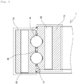
- Fig. 1 shows front and partial sectional views of a large-sized bearing (yaw bearing, blade bearing) of a wind power generator.
- Fig. 2 shows a partly enlarged sectional view of the large-sized bearing shown in Fig. 1 .
- a rolling bearing 1 of the present invention has an inner ring 2, an outer ring 3, and a plurality of rolling elements 4 as bearing members thereof.
- the rolling elements 4 are interposed between the inner ring 2 and the outer ring 3 in a double row or a single row with the rolling elements 4 being retained by a cage 5 or a spacer.
- Grease is packed as a lubricant in a space 6 of the rolling bearing 1 disposed on the periphery of the rolling elements.
- the rolling bearing 1 is fastened and fixed to a bearing box at an end surface of the inner ring 2 and/or an end surface of the outer ring 3.
- the rolling bearing 1 is fastened to the bearing box (not shown in Figs. 1 and 2 ) with bolts through a bolt hole 8 formed through each of the inner ring 2 and the outer ring 3.
- a gear 7 is mounted on the inner peripheral surface of the inner ring 2
- the gear 7 may be mounted on the outer peripheral surface of the outer ring in dependence on a portion where the rolling bearing 1 is disposed.
- Regions of the bearing members which are exposed to a corrosive environment include surfaces of the inner ring 2 and the outer ring 3 except the inner peripheral surface of the outer ring 3, the outer peripheral surface of the inner ring 2, and the surfaces of the rolling elements.
- a bearing end surface c of the outer ring 3 and a bearing end surface d of the inner ring 2 are surfaces of the bearing to be fixed to a bearing box (not shown in the drawings).
- a film having a sacrificial anode action to be described later is formed on regions including at least the surfaces (c, d) thereof to be fixed to the bearing box.
- the reference symbols a and c denote the bearing end surfaces of the outer ring3.
- the reference symbol b denotes the outer peripheral surface of the outer ring 3.
- the reference symbols d and e denote the bearing end surfaces of the inner ring 2.
- the reference symbol f denotes the inner peripheral surface (gear portion is excluded) of the inner ring 2.
- the film is formed on all of the surfaces (a through f) of the bearing members except the surface of the gear part, a groove part, holes, screws, a seal sliding surface, the inner peripheral surface of the outer ring 3, the outer peripheral surface of the inner ring 2, and the surfaces of the rolling elements 4.
- the surfaces of the bearing to be fixed thereto contact other members directly or indirectly.
- the film is formed partly or entirely on each of the surfaces of the bearing to be fixed thereto.
- the film formed by thermal spraying or the like on the surfaces (c, d) of the bearing to be fixed is not subjected to the sealing treatment, but the film is kept porous.
- the rolling bearing is fixed by fastening the rolling bearing thereto with a large number of bolts.
- the bolts provide an equal fastening force in fixing the rolling bearing.
- Fig. 3 shows a partly enlarged sectional view of a large-sized bearing (yaw bearing, blade bearing) of the wind power generator.
- the rolling bearing 1 having a mode shown in Fig. 3 is similar to the mode of the rolling bearing shown in Figs. 1 and 2 except that the rolling bearing 1 of this embodiment is not provided with the gear 7. Because the gear 7 is not mounted on the inner peripheral surface of the inner ring of the rolling bearing of this embodiment, the film having the sacrificial anode action is formed on the entire inner peripheral surface of the inner ring 2 in addition to the regions of the rolling bearing having the mode shown in Figs. 1 and 2 .
- Fig. 4 shows a sectional view of a seal-attached deep groove ball bearing.
- the rolling bearing 1 having a mode shown in Fig. 4 has a sealing member 9 which seals opening portions, of the inner ring 2 and the outer ring 3, disposed at both axial ends thereof.
- a film having the sacrificial anode action is formed on the bearing end surface (both width surfaces of the bearing), of each of the inner ring 2 and the outer ring 3, which is disposed at a side where a sealing surface of the sealing member is located.
- the rolling bearing 1 is used with the inner peripheral surface of the inner ring and the outer peripheral surface of the outer ring being fitted on other members.
- a part of each of the bearing end surface is the surface of the bearing to be fixed.
- the film is not formed on the inner peripheral surface of the inner ring and the outer peripheral surface of the outer ring both of which are surfaces to be fitted on other members, the film may be formed on these surfaces to be fitted on the other members as necessary.
- the rolling bearing of the present invention can be used as a self-aligning roller bearing, an angular ball bearing, a cylindrical roller bearing, a tapered roller bearing, a needle roller bearing, a thrust cylindrical roller bearing, a thrust tapered roller bearing, a thrust needle roller bearing, and a thrust self-aligning roller bearing.
- the base material of the bearing members examples include iron-based materials such as high carbon chromium bearing steel, cemented steel (case hardening steel), stainless steel, high-speed steel, and cold rolled steel, and hot rolled steel. It is possible to use the above-described steel materials subjected to high frequency heat treatment and nitriding treatment.
- the cemented steel is preferable as the base material of the bearing members (of large-sized rolling bearing in particular) of the present invention, because when it is carburized and quenched, it is hardened in a proper depth from its surface and forms a core having a comparatively low degree of hardness. Thereby the cemented steel is allowed to have both hardness and toughness and excellent shock resistance.
- iron-based alloy steels for machine structural use such as chromium-molybdenum steel represented by SCM445 and SCM440 and alloy steels for machine structural use (JIS G4051) represented by S48C and S50C are listed.
- the film of the present invention having the sacrificial anode action is capable of displaying the sacrificial anode action in relation to the base material of the bearing members. It is necessary for the film to contain a metal whose ionization tendency is higher than that of a metal composing the base material of the bearing members where the film is to be formed.
- the kind of the material of the bearing members and the film-forming method are not specifically limited.
- the ionization tendency means the order of a standard oxidation reduction potential between a hydrated metal ion and a metal in a water solution. In the case where the standard oxidation reduction potential is negative, the larger is the absolute value thereof, "the higher is the ionization tendency".
- the method of forming the film includes coating treatment to be made by using zinc rich paint containing zinc and thermal sprayed film treatment of using zinc, aluminum, an alloy or a pseudo alloy consisting of aluminum and zinc, an alloy consisting of aluminum and magnesium or an alloy consisting of aluminum and titanium as a spraying material.
- thermal spraying method it is possible to adopt known thermal spraying methods such as flame spraying method, arc spraying method, plasma spraying method, and laser spraying method. Of these thermal spraying methods, it is preferable to use the arc spraying method.
- arc spraying method arc is generated between two metal wires to fuse the metal wires. While the metal wires are being fed, droplets of fused metal wires refined by spraying a gas to the metal wires are sprayed to the base material of the bearing members to form a film thereon. It is possible to utilize the material containing zinc, aluminum or magnesium as the thermal spraying material. It is possible to easily secure close contact between the base material of the bearing members and the film formed by carrying out the arc spraying method.
- a thermal sprayed film is formed as a result of fusion of a large number of particles having different diameters in only the surface layers thereof.
- openings and gaps are generated at particle boundaries to form a porous film.
- the particles are liable to become smaller.
- pores of an obtained film (porous film) are liable to become smaller. Consequently on the surface of the bearing to be fixed, it is difficult to obtain the effect of preventing the fastening portion from loosening and stick-slip from occurring.
- the porosity of the thermal sprayed film is set to 3% to 40% and preferably 5% to 20%.
- the porosity thereof is adjustable according to a thermal spraying condition or the like. When the porosity thereof is less than 3%, it is difficult to obtain the effect of preventing the fastening portion from loosening and the stick-slip from occurring. On the other hand, in the case where the porosity thereof is more than 40%, there is a fear that the corrosion resistance cannot be sufficiently improved.
- the above-described range of the porosity thereof is suitable for the film formed on the surface of the bearing to be fixed. When the porosity thereof is adjusted in the above-described range, it is possible to deal with regions required to have higher corrosion resistance by the pore-sealing treatment or the like.
- the film disposed in the above-described region to treatment of sealing pores present in the film formed in the above-described region or to treatment of coating the surface of the film or to both treatments.
- the pore-sealing treatment is to seal a part or all of pores of the film having the sacrificial anode action in a region of the film other than the region of the film formed on the surface of the bearing to be fixed.
- the coating treatment is to coat a part or all of the film having the sacrificial anode action with a material not having the sacrificial anode action in the region of the film other than the region of the film formed on the surface of the bearing to be fixed.
- the pore-sealing treating method is not limited to a specific method, but it is possible to adopt any method capable of sealing a part or all of pores of the porous film formed by the thermal spraying treatment or the like.
- the material quality of a treating agent is not limited to a specific one either.
- the pore-sealing treating method includes a method of applying an organic pore-sealing agent such as epoxy resin, acrylic resin, urethane resin, phenol resin or fluororesin or an inorganic pore-sealing agent containing silicate, phosphate or alkoxysilane as its main component to the surface of the thermal sprayed film.
- the penetration and filling performance of the pore-sealing agent depend on a grain boundary fusing structure forming the thermal sprayed film to be treated. Therefore it is desirable to select the pore-sealing agent optimum for the grain boundary fusing structure of the thermal sprayed film and for properties demanded for the thermal sprayed film after the thermal sprayed film is subjected to the pore-sealing treatment.
- a material to be used in the coating treatment is not limited to a specific one, but it is possible to use any material not containing elements showing the sacrificial anodic property as its main component.
- Urethane paint and fluorine paint known as general-use paint are exemplified.
- the surface roughness thereof is set to favorably not more than 130 ⁇ mRz and more favorably not more than 100 ⁇ mRz. Because the film having the sacrificial anode action is formed on the surface of the bearing to be fixed to the bearing box, the film is demanded to have uniformity in its thickness . From the above, by setting the mutual error of the film thickness to not more than 100 ⁇ m, it is possible to prevent backlash from occurring, the degree of fixation of the bearing from decreasing, and the bearing from slipping from the bearing box due to the occurrence of the stick-slip during the operation of the bearing.
- the thickness of the film of the present invention having the sacrificial anode action is not specifically limited, provided that the film secures demanded degree of durability.
- the thickness of the film having the sacrificial anode action is set to favorably 10 to 500 ⁇ m, more favorably 50 to 500 ⁇ m, and most favorably 100 to 200 ⁇ m.
- the thickness of the film having the sacrificial anode action is set to favorably 10 to 500 ⁇ m, more favorably 50 to 500 ⁇ m, and most favorably 100 to 200 ⁇ m.
- the rolling bearing is used for a long term not less than 20 years in a very strict environment such as on the sea, as will be shown in the example, it is possible to exemplify a method of thermally spraying aluminum or an Al-Mg alloy consisting of aluminum and 5 vol% of magnesium added thereto to form a film having a thickness of not less than 100 ⁇ m, subjecting the obtained film to the pore-sealing treatment, and thereafter subjecting it to the coating treatment of setting the thickness of the coated film to not less than 100 ⁇ m.
- Grease to be packed in the space of the rolling bearing of the present invention as a lubricant can be used without limitation, provided that the grease is used for a rolling motion.
- the base oil composing the grease include mineral oil such as paraffin-based mineral oil and naphthene-based mineral oil; hydrocarbon-based synthetic oil such as polybutene oil, poly- ⁇ -olefin oil, alkylbenzene oil, and alkylnaphthalene oil; and non-hydrocarbon-based synthetic oil such as natural fat and oil, polyol ester oil, phosphate ester oil, diester oil, polyglycoloil, silicone oil, polyphenylether oil, alkyldiphenyl ether oil, and fluorinated oil.
- These base oils maybe used singly or in combination of not less than two kinds.
- the kinematic viscosity (40°C) of the base oil to be used in the present invention is favorably 30 to 600mm 2 /s.
- the kinematic viscosity of the base oil to be used for the large-sized bearing of the wind power generator is preferably 300 to 600mm 2 /s.
- thickeners composing grease include metal soap-based thickeners such as aluminum soap, lithium soap, sodium soap, lithium complex soap, calcium complex soap, and aluminum complex soap; urea-based compounds such as diurea compounds and polyurea compounds; and fluororesin powder such as PTFE resin. These thickeners may be used singly or in combination of not less than two kinds.
- additives can be added to grease as necessary.
- an extreme pressure agent such as organozinc compounds and organomolybdenum compounds
- an antioxidant such as amine-based compounds, phenol-based compounds, and sulfur-based compounds
- a wear inhibitor such as sulfur-based compounds and phosphorous-based compounds
- a rust-proofing agent such as polyhydric alcohol esters
- a viscosity index improver such as polymethacrylate and polystyrene
- solid lubricant such as molybdenum disulfide and graphite
- an oily agent such as ester and alcohol.
- the worked penetration (JIS K 2220) of a grease composition it is preferable to set the worked penetration (JIS K 2220) of a grease composition to the range of 200 to 350.
- the worked penetration thereof is less than 200, the degree of oil separation at low temperatures is low and thus defective lubrication takes place. Thereby fretting (fretting corrosion) is liable to occur in the case of the large-sized bearing of the wind power generator.
- fretting fretting corrosion
- the worked penetration thereof is more than 350, grease is soft and consequently liable to flow out of the bearing.
- Table 1 shows an example of treatment of forming a film on each rolling bearing which can be used in an aerial marine environment such as on the sea for a long term not less than 20 years (BS5493, Code of practice for protective coating of iron and steel structures against corrosions, British Standards Institution, 1977).
- Table 2 shows an example of treatment of forming a film on each rolling bearing which can be used on the sea for a long term not less than 10 years (BS5493, same as above).
- Table 3 shows an especially preferable example of treatment of forming a film on each rolling bearing which supports a blade of a wind power generator or its yaw.
- the rolling bearing shown in table 3 can be used for a long term not less than 20 years when it is used on the sea (BS5493, same as above).
- Two kinds of rolling bearings (1: K2N-TD33402PX1S30 ⁇ 1716 ⁇ 2080 ⁇ 168 provided with internal gear, 2: K2N-TD39101PX 1S30 ⁇ 2000 ⁇ 2400 ⁇ 205 (provided with internal gear) having a configuration shown in Figs. 1 and 2 were used in the examples. These rolling bearings were subjected to the film treatment shown in each table. The inner diameter of the inner ring of each rolling bearing was not less than 800mm. The base material of the inner ring and that of the outer ring subjected to the film treatment was SCM445H.
- AlMg5% shown in each table means an Al-Mg alloy consisting of aluminum and 5 vol% of magnesium added thereto.
- ZnA115% shown in each table means a Zn-Al alloy consisting of zinc and 15 vol% of aluminum added thereto. These two alloys were used as thermal spraying materials. The thermal spraying materials were subjected to arc spray to form a thermal sprayed film having the thicknesses shown in the tables on various regions of each rolling bearing.
- the reference symbols a through f shown in the tables correspond to the regions shown by the reference symbols a through f in Fig. 2 .
- the surface of the base material of each bearing member was treated in the order from (1) to (3) shown in the tables. Films formed on the regions c and d were porous and not subjected to the pore-sealing treatment and the coating treatment.
- epoxy resin-based pore-sealing agent was applied to the surface of each thermal sprayed film.
- Coating treatment was carried out by using urethane paint.
- an intermediate layer consisting of epoxy resin was formed by carrying out coating treatment to improve adhesion between each film and the urethane paint. Thereafter the urethane paint was applied to the intermediate layer.
- the thickness of "thermal spraying not less than 100 ⁇ m” applied to the regions a, b, e, and f in each example was 115 to 199 ⁇ m.
- the thickness of "thermal spraying not less than 100 ⁇ m” applied to the regions c and d in each example was 118 to 168 ⁇ m.
- the film thickness of the total of the thickness "thermal spraying + pore-sealing treatment + coating treatment" in the regions a, b, e, and f was 343 to 504 ⁇ m.
- Example Film formed by treating surface of base material of bearing member a, b, e, f c, d 1 (1)Thermal spraying of Al not less than 100 ⁇ m Thrmal spraying of Al not less than 100 ⁇ m (mutual difference not more than 100 ⁇ m) (2)Pore-sealing treatment (3) Coating not less than 100 ⁇ m 2 (1) Thermal spraying of AlMg5% not less than 100 ⁇ m Thrmal spraying of AlMg5% not less than 100 ⁇ m (mutual difference not more than 100 ⁇ m) (2)Pore-sealing treatment (3)Coating not less than 100 ⁇ m 3 (1)Thermal spraying of ZnAl5% not less than 100 ⁇ m Thrmal spraying of ZnA15% not less than 100 ⁇ m (mutual difference not more than 100 ⁇ m) (2)Pore-sealing treatment (3)Coating not less than 100 ⁇ m 4 (1)Thermal spraying of Zn not less than 100 ⁇ m Thrmal spraying
- the rolling bearing of the present invention can be large-sized, is excellent in its corrosion resistance, and is allowed to prevent the mounting accuracy from deteriorating, the fixing force from decreasing, and vibration from occurring at the portion of the bearing to be fixed to the bearing box or the like. Therefore the rolling bearing can be suitably utilized as the large-sized bearing in the highly humid environment, the environment where condensation is liable to occur, and the highly corrosive environment such as on the sea and the shore.
- the rolling bearing can be preferably utilized as a bearing which supports the blade of the wind power generator or the yaw thereof.
Claims (10)
- Rollenlager (1), beinhaltend einen inneren Ring (2), einen äußeren Ring (3) und Rollelemente (4) als Lagerelemente hiervon,
wobei aus Regionen der Lagerelemente, welche einer korrosiven Umgebung gegenüber exponiert sind, ein Film, welcher eine Wirkung einer Opferanode für ein Basismaterial der Lagerelemente besitzt, in einer Region gebildet ist, welche mindestens eine zu befestigende Fläche des Rollenlagers umfasst; und
der an der zu befestigenden Fläche des Lagers gebildete Film porös ist,
wobei das basische Material der Lagerelemente aus einem eisenbaiserenden Material besteht; und der Film, welcher die Wirkung einer Opferanode besitzt, aus einem Material besteht, welches eines der Elemente Zink, Aluminium und Magnesium enthält, und
wobei der Film, welcher die Wirkung einer Opferanode besitzt, ein thermisch gesprühter Film ist, gebildet durch Verwendung des Materials als ein thermisches Sprühmaterial. - Rollenlager nach Anspruch 1, bei welchem der Film mit einer Wirkung einer Opferanode für ein Basismaterial der Lagerelemente ein thermisch gesprühter Film mit einer Porosität von 3 % bis 40 % ist.
- Rollenlager nach Anspruch 2, bei welchem die Porosität des thermisch gesprühten Films 5 % bis 20 % beträgt.
- Rollenlager (1) nach einem der Ansprüche 1 bis 3, welches an einem Lagergehäuse an einer Endfläche (d) des inneren Rings (2) und/oder an einer Endfläche (c) des äußeren Rings (3) angebracht und befestigt ist; und wobei die Lagerendfläche diejenige Fläche des Lagers ist, die an dem Lagergehäuse zu befestigen ist.
- Rollenlager (1) nach einem der Ansprüche 1 bis 3, welches ein Dichtelement besitzt, welches Öffnungsabschnitte des inneren Rings (2) und des äußeren Rings (3) dicht verschließt, welche an beiden axialen Enden hiervon angeordnet sind; und wobei ein Film, welcher die Wirkung einer Opferanode besitzt, an einer Lagerendfläche (c, d) eines jeden von dem inneren Ring (2) und dem äußeren Ring (3) gebildet ist, welche an einer Seite angeordnet ist, an welcher eine Dichtfläche des Dichtelements befindlich ist.
- Rollenlager (1) nach einem der Ansprüche 1 bis 3, bei welchem ein Teil oder sämtliche Poren des Films, welcher die Wirkung einer Opferanode besitzt, in einer Region des Films dicht verschlossen sind, welche sich von einer Region des Films unterscheidet, welche an der zu befestigenden Fläche des Lagers gebildet ist.
- Rollenlager (1) nach einem der Ansprüche 1 bis 3, bei welchem ein Teil des Films oder der gesamte Film, welcher die Wirkung einer Opferanode besitzt, mit einem Material beschichtet ist, welches nicht die Wirkung einer Opferanode in einer Region des Films besitzt, welche sich von einer Region des Films unterscheidet, welche an der zu befestigenden Fläche des Lagers gebildet ist.
- Rollenlager (1) nach einem der Ansprüche 1 bis 3, bei welchem ein Innendurchmesser des inneren Rings (2) nicht unter 800 mm beträgt.
- Rollenlager (1) nach einem der Ansprüche 1 bis 3, welches für einen Generator oder für ein Stromerzeugungsgerät eingesetzt wird, welches Strom aus natürlicher Energie erzeugt.
- Rollenlager nach Anspruch 9, welches ein Blatt eines Windstromgenerators oder eine Azimutverstellung hiervon trägt.
Applications Claiming Priority (2)
| Application Number | Priority Date | Filing Date | Title |
|---|---|---|---|
| JP2011181713A JP5905681B2 (ja) | 2011-08-23 | 2011-08-23 | 転がり軸受 |
| PCT/JP2012/070347 WO2013027597A1 (ja) | 2011-08-23 | 2012-08-09 | 転がり軸受 |
Publications (3)
| Publication Number | Publication Date |
|---|---|
| EP2749781A1 EP2749781A1 (de) | 2014-07-02 |
| EP2749781A4 EP2749781A4 (de) | 2015-07-22 |
| EP2749781B1 true EP2749781B1 (de) | 2018-07-25 |
Family
ID=47746344
Family Applications (1)
| Application Number | Title | Priority Date | Filing Date |
|---|---|---|---|
| EP12825668.2A Revoked EP2749781B1 (de) | 2011-08-23 | 2012-08-09 | Rollenlager |
Country Status (7)
| Country | Link |
|---|---|
| US (1) | US9011014B2 (de) |
| EP (1) | EP2749781B1 (de) |
| JP (1) | JP5905681B2 (de) |
| KR (1) | KR101947211B1 (de) |
| CN (1) | CN103765025B (de) |
| IN (1) | IN2014DN01964A (de) |
| WO (1) | WO2013027597A1 (de) |
Families Citing this family (18)
| Publication number | Priority date | Publication date | Assignee | Title |
|---|---|---|---|---|
| FR2992708B1 (fr) * | 2012-06-29 | 2015-03-27 | Saint Gobain Pont A Mousson | Revetement exterieur pour element de tuyauterie enterre a base de fer, element de tuyauterie revetu et procede de depot du revetement |
| DE102012218619A1 (de) * | 2012-10-12 | 2014-04-17 | Schaeffler Technologies Gmbh & Co. Kg | Mediengeschmiertes Lager |
| DE102014215347B4 (de) * | 2014-08-04 | 2022-07-07 | Aktiebolaget Skf | Lagerring und Lageranordnung |
| CA3101528C (en) * | 2014-09-02 | 2023-07-25 | Saint-Gobain Performance Plastics Pampus Gmbh | Corrosion resistant bushing |
| CN104405770B (zh) * | 2014-10-29 | 2016-10-05 | 江阴尚爵回转驱动制造有限公司 | 回转支承的尺寸链控制及表面喷粉工艺 |
| JP2016156409A (ja) * | 2015-02-23 | 2016-09-01 | Ntn株式会社 | 転がり軸受 |
| FR3045561B1 (fr) | 2015-12-17 | 2020-06-05 | Ntn-Snr Roulements | Roulement d'un pied de pale lubrifie |
| DE102016217366A1 (de) | 2016-09-13 | 2018-03-15 | Schaeffler Technologies AG & Co. KG | Lagerring mit einer elektrisch isolierenden Beschichtung sowie Verfahren zur Herstellung einer elektrisch isolierenden Beschichtung |
| WO2018143138A1 (ja) * | 2017-02-02 | 2018-08-09 | 日本精工株式会社 | 転がり軸受 |
| JP2018204642A (ja) * | 2017-05-31 | 2018-12-27 | 中西金属工業株式会社 | 回転用シール |
| JP2019066011A (ja) * | 2017-10-04 | 2019-04-25 | 中西金属工業株式会社 | 回転用シール |
| DE102017222919A1 (de) * | 2017-12-15 | 2019-06-19 | Aktiebolaget Skf | Wälzlager |
| DE102017222918A1 (de) | 2017-12-15 | 2019-06-19 | Aktiebolaget Skf | Wälzlageranordnung |
| DE202018102121U1 (de) * | 2018-04-17 | 2019-07-19 | Liebherr-Components Biberach Gmbh | Großwälzlager |
| CN110848267A (zh) * | 2019-12-27 | 2020-02-28 | 瓦房店轴承集团国家轴承工程技术研究中心有限公司 | S形定位回转径结构的偏航轴承 |
| CN110977363B (zh) * | 2019-12-27 | 2021-07-06 | 瓦房店轴承集团国家轴承工程技术研究中心有限公司 | 一种斜面变桨轴承的加工工艺 |
| EP3851668A1 (de) * | 2020-01-17 | 2021-07-21 | Wobben Properties GmbH | Windenergieanlage, windenergieanlagen- rotorblatt und blattlagerung für eine windenergieanlage |
| DE102021211758A1 (de) | 2021-10-19 | 2021-12-02 | Thyssenkrupp Ag | Haftstarke Verbindung in einem Rollenlager |
Citations (9)
| Publication number | Priority date | Publication date | Assignee | Title |
|---|---|---|---|---|
| US3862851A (en) | 1971-05-17 | 1975-01-28 | Chromalloy American Corp | Method of producing Magnesium-Based coating for the sacrificial protection of metals |
| USRE35860E (en) * | 1991-06-05 | 1998-07-28 | Mpb Corporation | Corrosion-resistant zinc-nickel plated bearing races |
| US20050078897A1 (en) | 2003-10-09 | 2005-04-14 | Ming Zhang | Protection of railway axle and bearing against corrosion |
| DE102005020653A1 (de) | 2005-05-03 | 2006-11-09 | Schaeffler Kg | Abgedichtetes Radialwälzlager, insbesondere Radlager eines Kraftfahrzeuges |
| JP2008069925A (ja) | 2006-09-15 | 2008-03-27 | Ntn Corp | 絶縁転がり軸受および風力発電装置用転がり軸受 |
| JP2008169959A (ja) | 2007-01-15 | 2008-07-24 | Nsk Ltd | 電食防止用絶縁転がり軸受 |
| WO2008145163A1 (en) | 2007-05-31 | 2008-12-04 | Ab Skf | A wheel hub unit for a vehicle |
| DE102009017192A1 (de) | 2009-04-09 | 2010-10-14 | Aktiebolaget Skf | Lageranordnung für eine Tragrolle |
| JP2011007247A (ja) | 2009-06-25 | 2011-01-13 | Ntn Corp | 旋回軸受およびこれを用いた風力発電装置 |
Family Cites Families (23)
| Publication number | Priority date | Publication date | Assignee | Title |
|---|---|---|---|---|
| US3870607A (en) * | 1971-04-21 | 1975-03-11 | Avco Corp | Bearing Manufacture |
| US4452539A (en) * | 1981-10-26 | 1984-06-05 | Varel Manufacturing Company | Bearing seal for rotating cutter drill bit |
| JPS6069845A (ja) * | 1983-09-24 | 1985-04-20 | Toshiba Corp | 情報記録担体 |
| US4692231A (en) * | 1985-02-06 | 1987-09-08 | St Onge Henri S | Apparatus for cathodic protection of metal piping |
| JPS6324076A (ja) * | 1986-03-06 | 1988-02-01 | Mitsubishi Heavy Ind Ltd | 鋼材の防錆下地膜形成方法 |
| US4932795A (en) * | 1988-11-10 | 1990-06-12 | Outboard Marine Corporation | Electrically conductive plastic bushings for marine propulsion devices |
| JPH0427742A (ja) * | 1990-05-18 | 1992-01-30 | Isuzu Motors Ltd | アルミニウムシリンダヘッドに於ける冷却水通路の犠性被膜形成方法 |
| JPH0482431A (ja) | 1990-07-25 | 1992-03-16 | Sumitomo Electric Ind Ltd | 移動体無線通信方式 |
| JPH0482431U (de) | 1990-11-28 | 1992-07-17 | ||
| JP2526195Y2 (ja) | 1991-04-03 | 1997-02-19 | 日本精工株式会社 | 軸受装置 |
| NO172608C (no) * | 1991-04-25 | 1993-08-11 | Alcatel Stk As | Fleksibel undersjoeisk linje |
| ES2073969B1 (es) * | 1992-11-06 | 1998-04-01 | Estevez Andres Herrera | Sistema para la proteccion contra la corrosion del tubo de escape de humos y del catalizador anticontaminacion de los vehiculos de motor a combustion interna. |
| JPH06313435A (ja) | 1993-04-30 | 1994-11-08 | Nippon Seiko Kk | 耐食性転がり軸受 |
| US5330016A (en) * | 1993-05-07 | 1994-07-19 | Barold Technology, Inc. | Drill bit and other downhole tools having electro-negative surfaces and sacrificial anodes to reduce mud balling |
| JPH07301241A (ja) | 1994-04-28 | 1995-11-14 | Ntn Corp | 耐食性軸受 |
| NL1009170C2 (nl) * | 1998-05-14 | 1999-11-16 | Skf Eng & Res Centre Bv | Bekleed wentellager. |
| JP3811575B2 (ja) * | 1998-10-29 | 2006-08-23 | 株式会社ジェイテクト | 軸受用保持器 |
| JP3724480B2 (ja) * | 2000-07-18 | 2005-12-07 | 日本精工株式会社 | 転動装置 |
| US6994475B2 (en) * | 2003-03-14 | 2006-02-07 | The Timken Company | Coated rolling element bearing cages |
| FR2859256B1 (fr) * | 2003-08-27 | 2006-11-24 | Defontaine Sa | Couronne d'orientation |
| JP2005133876A (ja) * | 2003-10-31 | 2005-05-26 | Ntn Corp | 電食防止型転がり軸受 |
| EP1921335A1 (de) * | 2005-08-08 | 2008-05-14 | Ntn Corporation | Mit einem sensor ausgestattetes lager für ein rad |
| DE102008048412A1 (de) * | 2008-05-08 | 2009-11-12 | Schaeffler Kg | Lagermodul |
-
2011
- 2011-08-23 JP JP2011181713A patent/JP5905681B2/ja active Active
-
2012
- 2012-08-09 CN CN201280040709.3A patent/CN103765025B/zh active Active
- 2012-08-09 IN IN1964DEN2014 patent/IN2014DN01964A/en unknown
- 2012-08-09 KR KR1020147007435A patent/KR101947211B1/ko active IP Right Grant
- 2012-08-09 US US14/240,402 patent/US9011014B2/en active Active
- 2012-08-09 WO PCT/JP2012/070347 patent/WO2013027597A1/ja active Application Filing
- 2012-08-09 EP EP12825668.2A patent/EP2749781B1/de not_active Revoked
Patent Citations (11)
| Publication number | Priority date | Publication date | Assignee | Title |
|---|---|---|---|---|
| US3862851A (en) | 1971-05-17 | 1975-01-28 | Chromalloy American Corp | Method of producing Magnesium-Based coating for the sacrificial protection of metals |
| USRE35860E (en) * | 1991-06-05 | 1998-07-28 | Mpb Corporation | Corrosion-resistant zinc-nickel plated bearing races |
| USRE35860F1 (en) * | 1991-06-05 | 2001-01-02 | Timken Co | Corrosion-resistant zinc-nickel plated bearing races |
| US20050078897A1 (en) | 2003-10-09 | 2005-04-14 | Ming Zhang | Protection of railway axle and bearing against corrosion |
| DE102005020653A1 (de) | 2005-05-03 | 2006-11-09 | Schaeffler Kg | Abgedichtetes Radialwälzlager, insbesondere Radlager eines Kraftfahrzeuges |
| US20080187262A1 (en) * | 2005-05-03 | 2008-08-07 | Schaeffler Kg | Sealed Radial Rolling Bearing, In Particular Wheel Bearing For a Motor Vehicle |
| JP2008069925A (ja) | 2006-09-15 | 2008-03-27 | Ntn Corp | 絶縁転がり軸受および風力発電装置用転がり軸受 |
| JP2008169959A (ja) | 2007-01-15 | 2008-07-24 | Nsk Ltd | 電食防止用絶縁転がり軸受 |
| WO2008145163A1 (en) | 2007-05-31 | 2008-12-04 | Ab Skf | A wheel hub unit for a vehicle |
| DE102009017192A1 (de) | 2009-04-09 | 2010-10-14 | Aktiebolaget Skf | Lageranordnung für eine Tragrolle |
| JP2011007247A (ja) | 2009-06-25 | 2011-01-13 | Ntn Corp | 旋回軸受およびこれを用いた風力発電装置 |
Non-Patent Citations (12)
| Title |
|---|
| ANONYMOUS: "Metallic and other inorganic coatings - Thermal spraying- Zinc, aluminium and their alloys", ISO 2063:1991 (E), 1 November 1991 (1991-11-01), pages i-iii, 1 - 10, XP055586258 |
| ANONYMOUS: "Metallic and other inorganic coatings- Thermal spraying- Zinc, aluminium and their alloys", EUROPEAN STANDARD EN 22063:1994, 1994, XP055586270 |
| ANONYMOUS: "Rothe Erde Großwälzlager. Einsatzgebiet: Windenergieanlagen", THYSSENKRUPP ROTHE ERDE PRODUKTKATALOG, January 2003 (2003-01-01), pages 1 - 16, XP055579466 |
| ANONYMOUS: "Thermisches Spritzen - Metallische und andere anorganische Schichten -Zink, Aluminium und ihre Legierungen", DEUTSCHE NORM DIN EN ISO 2063, May 2005 (2005-05-01), pages 1 - 19, XP055579448 |
| ANONYMOUS: "Thermisches Spritzen: Zink, Aluminium und ihre Legierungen", DEUTSCHE NORM DIN EN 22063, August 1994 (1994-08-01), XP055579449 |
| ANONYMOUS: "Zink und Beschichtung- eine Kombination mit "Mehrwert"", KORRONEWS, January 2006 (2006-01-01), pages 1 - 12, XP055586253 |
| C.M. COTELL, J.A. SPRAGUE, F.A. SMIDT: "ASM Handbook, Volume 5- Surface Engineering", vol. 5, 1994, ASM INTERNATIONAL, article ROBERT C. ET AL.: "Thermal Spray Coatings", pages: 497 - 509, XP055262083 |
| G.F. KULAK ET AL.: "Guide to Design Criteria for Bolted and Riveted Joints. 2nd Ed", vol. 215, 2001, AISC, article "Surface coatings", pages: 198 - 208, XP055579452 |
| J.R. DAVIS: "Handbook of Thermal Spray Technology", 2004, ASM, article "Sacrificial coatings", pages: 194 - 197, XP055579451 |
| L. PAWLOWSKI: "The Science and Engineering of Thermal Spray Coatings, 2nd ed.", 2008, JOHN WILEY & SONS, LTD, pages: 67 - 82 , 359- 363, XP055579450 |
| MARITA BÜTEFÜHR: "Einfluss des Aluminiumgehaltes gespritzter Zinküberzüge auf den Korrosionsschutz von Stahl", DISSERTATION, 2006, pages 1 - 129, XP055586243 |
| THE STEEL CONSTRUCTION INSTITUTE: "Steel Bridge Group: Thermally sprayed metal coatings", GUIDANCE NOTE NO. 8.04, 2009, pages 1 - 8, XP055579453 |
Also Published As
| Publication number | Publication date |
|---|---|
| EP2749781A1 (de) | 2014-07-02 |
| US9011014B2 (en) | 2015-04-21 |
| CN103765025B (zh) | 2017-02-15 |
| JP5905681B2 (ja) | 2016-04-20 |
| KR101947211B1 (ko) | 2019-02-12 |
| EP2749781A4 (de) | 2015-07-22 |
| US20140177990A1 (en) | 2014-06-26 |
| IN2014DN01964A (de) | 2015-05-15 |
| CN103765025A (zh) | 2014-04-30 |
| JP2013044367A (ja) | 2013-03-04 |
| WO2013027597A1 (ja) | 2013-02-28 |
| KR20140067055A (ko) | 2014-06-03 |
Similar Documents
| Publication | Publication Date | Title |
|---|---|---|
| EP2749781B1 (de) | Rollenlager | |
| US11137030B2 (en) | Coating method for bearing ring | |
| US6994474B2 (en) | Rolling sliding member and rolling apparatus | |
| CN104235186B (zh) | 接头轴承润滑剂系统 | |
| WO2011122662A1 (ja) | 転がり軸受 | |
| US10190633B2 (en) | Rolling bearing | |
| JPH08100819A (ja) | 固体滑剤コーテイングを有するグリース潤滑ローリング素子ベアリング | |
| JP2008309312A (ja) | ころ軸受および風力発電機の回転軸支持構造 | |
| US10125821B2 (en) | Lubricated rolling bearing for blade roots | |
| JPH07127644A (ja) | 耐食軸受 | |
| JP2006250316A (ja) | 転動装置 | |
| CN105020265A (zh) | 一种风电机组变桨轴承与其防腐处理方法 | |
| CA2728945C (en) | Roller bearing for underwater applications | |
| JP2007002912A (ja) | 転がり軸受 | |
| JP4513775B2 (ja) | 圧延機ロールネック用転動装置 | |
| JP2014077522A (ja) | 軸受 | |
| JP2009204078A (ja) | 転動装置 | |
| JP2014234901A (ja) | 転がり軸受 | |
| JP5485922B2 (ja) | 転動装置 | |
| JP2007100870A (ja) | 転動装置 | |
| JP2009197872A (ja) | 転動装置 | |
| JP2009030628A (ja) | 直動装置 | |
| JP2010065842A (ja) | 車輪用軸受装置およびその製造方法 | |
| JP2008151301A (ja) | 直動転がり支持装置 | |
| CN103174924A (zh) | 一种复合固体润滑潜伏式润滑方法 |
Legal Events
| Date | Code | Title | Description |
|---|---|---|---|
| PUAI | Public reference made under article 153(3) epc to a published international application that has entered the european phase |
Free format text: ORIGINAL CODE: 0009012 |
|
| 17P | Request for examination filed |
Effective date: 20140307 |
|
| AK | Designated contracting states |
Kind code of ref document: A1 Designated state(s): AL AT BE BG CH CY CZ DE DK EE ES FI FR GB GR HR HU IE IS IT LI LT LU LV MC MK MT NL NO PL PT RO RS SE SI SK SM TR |
|
| DAX | Request for extension of the european patent (deleted) | ||
| RA4 | Supplementary search report drawn up and despatched (corrected) |
Effective date: 20150622 |
|
| RIC1 | Information provided on ipc code assigned before grant |
Ipc: F16C 33/64 20060101ALI20150616BHEP Ipc: F16C 33/62 20060101AFI20150616BHEP Ipc: F03D 11/00 20060101ALI20150616BHEP Ipc: F16C 33/76 20060101ALN20150616BHEP Ipc: F16C 19/08 20060101ALN20150616BHEP |
|
| STAA | Information on the status of an ep patent application or granted ep patent |
Free format text: STATUS: EXAMINATION IS IN PROGRESS |
|
| 17Q | First examination report despatched |
Effective date: 20170609 |
|
| GRAP | Despatch of communication of intention to grant a patent |
Free format text: ORIGINAL CODE: EPIDOSNIGR1 |
|
| RIC1 | Information provided on ipc code assigned before grant |
Ipc: F16C 33/64 20060101ALI20180208BHEP Ipc: F03D 80/70 20160101ALI20180208BHEP Ipc: F16C 33/62 20060101AFI20180208BHEP Ipc: F16C 33/76 20060101ALN20180208BHEP Ipc: F16C 19/18 20060101ALN20180208BHEP Ipc: F16C 19/52 20060101ALN20180208BHEP Ipc: F16C 19/06 20060101ALN20180208BHEP |
|
| STAA | Information on the status of an ep patent application or granted ep patent |
Free format text: STATUS: GRANT OF PATENT IS INTENDED |
|
| RIC1 | Information provided on ipc code assigned before grant |
Ipc: F16C 33/76 20060101ALN20180215BHEP Ipc: F16C 19/52 20060101ALN20180215BHEP Ipc: F16C 19/18 20060101ALN20180215BHEP Ipc: F16C 19/06 20060101ALN20180215BHEP Ipc: F16C 33/64 20060101ALI20180215BHEP Ipc: F16C 33/62 20060101AFI20180215BHEP Ipc: F03D 80/70 20160101ALI20180215BHEP |
|
| INTG | Intention to grant announced |
Effective date: 20180315 |
|
| GRAS | Grant fee paid |
Free format text: ORIGINAL CODE: EPIDOSNIGR3 |
|
| GRAA | (expected) grant |
Free format text: ORIGINAL CODE: 0009210 |
|
| STAA | Information on the status of an ep patent application or granted ep patent |
Free format text: STATUS: THE PATENT HAS BEEN GRANTED |
|
| REG | Reference to a national code |
Ref country code: FR Ref legal event code: PLFP Year of fee payment: 7 |
|
| AK | Designated contracting states |
Kind code of ref document: B1 Designated state(s): AL AT BE BG CH CY CZ DE DK EE ES FI FR GB GR HR HU IE IS IT LI LT LU LV MC MK MT NL NO PL PT RO RS SE SI SK SM TR |
|
| REG | Reference to a national code |
Ref country code: GB Ref legal event code: FG4D |
|
| REG | Reference to a national code |
Ref country code: CH Ref legal event code: EP |
|
| REG | Reference to a national code |
Ref country code: AT Ref legal event code: REF Ref document number: 1022097 Country of ref document: AT Kind code of ref document: T Effective date: 20180815 |
|
| REG | Reference to a national code |
Ref country code: IE Ref legal event code: FG4D |
|
| REG | Reference to a national code |
Ref country code: DE Ref legal event code: R096 Ref document number: 602012048956 Country of ref document: DE |
|
| REG | Reference to a national code |
Ref country code: NL Ref legal event code: MP Effective date: 20180725 |
|
| REG | Reference to a national code |
Ref country code: LT Ref legal event code: MG4D |
|
| PG25 | Lapsed in a contracting state [announced via postgrant information from national office to epo] |
Ref country code: NL Free format text: LAPSE BECAUSE OF FAILURE TO SUBMIT A TRANSLATION OF THE DESCRIPTION OR TO PAY THE FEE WITHIN THE PRESCRIBED TIME-LIMIT Effective date: 20180725 |
|
| REG | Reference to a national code |
Ref country code: AT Ref legal event code: MK05 Ref document number: 1022097 Country of ref document: AT Kind code of ref document: T Effective date: 20180725 |
|
| PG25 | Lapsed in a contracting state [announced via postgrant information from national office to epo] |
Ref country code: SE Free format text: LAPSE BECAUSE OF FAILURE TO SUBMIT A TRANSLATION OF THE DESCRIPTION OR TO PAY THE FEE WITHIN THE PRESCRIBED TIME-LIMIT Effective date: 20180725 Ref country code: AT Free format text: LAPSE BECAUSE OF FAILURE TO SUBMIT A TRANSLATION OF THE DESCRIPTION OR TO PAY THE FEE WITHIN THE PRESCRIBED TIME-LIMIT Effective date: 20180725 Ref country code: BG Free format text: LAPSE BECAUSE OF FAILURE TO SUBMIT A TRANSLATION OF THE DESCRIPTION OR TO PAY THE FEE WITHIN THE PRESCRIBED TIME-LIMIT Effective date: 20181025 Ref country code: NO Free format text: LAPSE BECAUSE OF FAILURE TO SUBMIT A TRANSLATION OF THE DESCRIPTION OR TO PAY THE FEE WITHIN THE PRESCRIBED TIME-LIMIT Effective date: 20181025 Ref country code: GR Free format text: LAPSE BECAUSE OF FAILURE TO SUBMIT A TRANSLATION OF THE DESCRIPTION OR TO PAY THE FEE WITHIN THE PRESCRIBED TIME-LIMIT Effective date: 20181026 Ref country code: LT Free format text: LAPSE BECAUSE OF FAILURE TO SUBMIT A TRANSLATION OF THE DESCRIPTION OR TO PAY THE FEE WITHIN THE PRESCRIBED TIME-LIMIT Effective date: 20180725 Ref country code: FI Free format text: LAPSE BECAUSE OF FAILURE TO SUBMIT A TRANSLATION OF THE DESCRIPTION OR TO PAY THE FEE WITHIN THE PRESCRIBED TIME-LIMIT Effective date: 20180725 Ref country code: RS Free format text: LAPSE BECAUSE OF FAILURE TO SUBMIT A TRANSLATION OF THE DESCRIPTION OR TO PAY THE FEE WITHIN THE PRESCRIBED TIME-LIMIT Effective date: 20180725 Ref country code: IS Free format text: LAPSE BECAUSE OF FAILURE TO SUBMIT A TRANSLATION OF THE DESCRIPTION OR TO PAY THE FEE WITHIN THE PRESCRIBED TIME-LIMIT Effective date: 20181125 Ref country code: PL Free format text: LAPSE BECAUSE OF FAILURE TO SUBMIT A TRANSLATION OF THE DESCRIPTION OR TO PAY THE FEE WITHIN THE PRESCRIBED TIME-LIMIT Effective date: 20180725 |
|
| PG25 | Lapsed in a contracting state [announced via postgrant information from national office to epo] |
Ref country code: AL Free format text: LAPSE BECAUSE OF FAILURE TO SUBMIT A TRANSLATION OF THE DESCRIPTION OR TO PAY THE FEE WITHIN THE PRESCRIBED TIME-LIMIT Effective date: 20180725 Ref country code: LV Free format text: LAPSE BECAUSE OF FAILURE TO SUBMIT A TRANSLATION OF THE DESCRIPTION OR TO PAY THE FEE WITHIN THE PRESCRIBED TIME-LIMIT Effective date: 20180725 Ref country code: HR Free format text: LAPSE BECAUSE OF FAILURE TO SUBMIT A TRANSLATION OF THE DESCRIPTION OR TO PAY THE FEE WITHIN THE PRESCRIBED TIME-LIMIT Effective date: 20180725 |
|
| REG | Reference to a national code |
Ref country code: DE Ref legal event code: R026 Ref document number: 602012048956 Country of ref document: DE |
|
| PLBI | Opposition filed |
Free format text: ORIGINAL CODE: 0009260 |
|
| REG | Reference to a national code |
Ref country code: CH Ref legal event code: PL |
|
| PG25 | Lapsed in a contracting state [announced via postgrant information from national office to epo] |
Ref country code: RO Free format text: LAPSE BECAUSE OF FAILURE TO SUBMIT A TRANSLATION OF THE DESCRIPTION OR TO PAY THE FEE WITHIN THE PRESCRIBED TIME-LIMIT Effective date: 20180725 Ref country code: CH Free format text: LAPSE BECAUSE OF NON-PAYMENT OF DUE FEES Effective date: 20180831 Ref country code: LI Free format text: LAPSE BECAUSE OF NON-PAYMENT OF DUE FEES Effective date: 20180831 Ref country code: ES Free format text: LAPSE BECAUSE OF FAILURE TO SUBMIT A TRANSLATION OF THE DESCRIPTION OR TO PAY THE FEE WITHIN THE PRESCRIBED TIME-LIMIT Effective date: 20180725 Ref country code: EE Free format text: LAPSE BECAUSE OF FAILURE TO SUBMIT A TRANSLATION OF THE DESCRIPTION OR TO PAY THE FEE WITHIN THE PRESCRIBED TIME-LIMIT Effective date: 20180725 Ref country code: LU Free format text: LAPSE BECAUSE OF NON-PAYMENT OF DUE FEES Effective date: 20180809 Ref country code: MC Free format text: LAPSE BECAUSE OF FAILURE TO SUBMIT A TRANSLATION OF THE DESCRIPTION OR TO PAY THE FEE WITHIN THE PRESCRIBED TIME-LIMIT Effective date: 20180725 Ref country code: IT Free format text: LAPSE BECAUSE OF FAILURE TO SUBMIT A TRANSLATION OF THE DESCRIPTION OR TO PAY THE FEE WITHIN THE PRESCRIBED TIME-LIMIT Effective date: 20180725 Ref country code: CZ Free format text: LAPSE BECAUSE OF FAILURE TO SUBMIT A TRANSLATION OF THE DESCRIPTION OR TO PAY THE FEE WITHIN THE PRESCRIBED TIME-LIMIT Effective date: 20180725 |
|
| 26 | Opposition filed |
Opponent name: THYSSENKRUPP ROTHE ERDE GMBH Effective date: 20190325 |
|
| PLBI | Opposition filed |
Free format text: ORIGINAL CODE: 0009260 |
|
| REG | Reference to a national code |
Ref country code: BE Ref legal event code: MM Effective date: 20180831 |
|
| PLAX | Notice of opposition and request to file observation + time limit sent |
Free format text: ORIGINAL CODE: EPIDOSNOBS2 |
|
| REG | Reference to a national code |
Ref country code: IE Ref legal event code: MM4A |
|
| PG25 | Lapsed in a contracting state [announced via postgrant information from national office to epo] |
Ref country code: SK Free format text: LAPSE BECAUSE OF FAILURE TO SUBMIT A TRANSLATION OF THE DESCRIPTION OR TO PAY THE FEE WITHIN THE PRESCRIBED TIME-LIMIT Effective date: 20180725 Ref country code: SM Free format text: LAPSE BECAUSE OF FAILURE TO SUBMIT A TRANSLATION OF THE DESCRIPTION OR TO PAY THE FEE WITHIN THE PRESCRIBED TIME-LIMIT Effective date: 20180725 Ref country code: DK Free format text: LAPSE BECAUSE OF FAILURE TO SUBMIT A TRANSLATION OF THE DESCRIPTION OR TO PAY THE FEE WITHIN THE PRESCRIBED TIME-LIMIT Effective date: 20180725 |
|
| 26 | Opposition filed |
Opponent name: SKF GMBH Effective date: 20190425 |
|
| GBPC | Gb: european patent ceased through non-payment of renewal fee |
Effective date: 20181025 |
|
| PG25 | Lapsed in a contracting state [announced via postgrant information from national office to epo] |
Ref country code: IE Free format text: LAPSE BECAUSE OF NON-PAYMENT OF DUE FEES Effective date: 20180809 |
|
| PG25 | Lapsed in a contracting state [announced via postgrant information from national office to epo] |
Ref country code: SI Free format text: LAPSE BECAUSE OF FAILURE TO SUBMIT A TRANSLATION OF THE DESCRIPTION OR TO PAY THE FEE WITHIN THE PRESCRIBED TIME-LIMIT Effective date: 20180725 Ref country code: BE Free format text: LAPSE BECAUSE OF NON-PAYMENT OF DUE FEES Effective date: 20180831 |
|
| PLBB | Reply of patent proprietor to notice(s) of opposition received |
Free format text: ORIGINAL CODE: EPIDOSNOBS3 |
|
| PG25 | Lapsed in a contracting state [announced via postgrant information from national office to epo] |
Ref country code: GB Free format text: LAPSE BECAUSE OF NON-PAYMENT OF DUE FEES Effective date: 20181025 |
|
| PG25 | Lapsed in a contracting state [announced via postgrant information from national office to epo] |
Ref country code: MT Free format text: LAPSE BECAUSE OF NON-PAYMENT OF DUE FEES Effective date: 20180809 |
|
| PLAB | Opposition data, opponent's data or that of the opponent's representative modified |
Free format text: ORIGINAL CODE: 0009299OPPO |
|
| PG25 | Lapsed in a contracting state [announced via postgrant information from national office to epo] |
Ref country code: TR Free format text: LAPSE BECAUSE OF FAILURE TO SUBMIT A TRANSLATION OF THE DESCRIPTION OR TO PAY THE FEE WITHIN THE PRESCRIBED TIME-LIMIT Effective date: 20180725 |
|
| R26 | Opposition filed (corrected) |
Opponent name: THYSSENKRUPP ROTHE ERDE GERMANY GMBH Effective date: 20190325 |
|
| PG25 | Lapsed in a contracting state [announced via postgrant information from national office to epo] |
Ref country code: HU Free format text: LAPSE BECAUSE OF FAILURE TO SUBMIT A TRANSLATION OF THE DESCRIPTION OR TO PAY THE FEE WITHIN THE PRESCRIBED TIME-LIMIT; INVALID AB INITIO Effective date: 20120809 Ref country code: PT Free format text: LAPSE BECAUSE OF FAILURE TO SUBMIT A TRANSLATION OF THE DESCRIPTION OR TO PAY THE FEE WITHIN THE PRESCRIBED TIME-LIMIT Effective date: 20180725 |
|
| PG25 | Lapsed in a contracting state [announced via postgrant information from national office to epo] |
Ref country code: MK Free format text: LAPSE BECAUSE OF NON-PAYMENT OF DUE FEES Effective date: 20180725 Ref country code: CY Free format text: LAPSE BECAUSE OF FAILURE TO SUBMIT A TRANSLATION OF THE DESCRIPTION OR TO PAY THE FEE WITHIN THE PRESCRIBED TIME-LIMIT Effective date: 20180725 |
|
| PGFP | Annual fee paid to national office [announced via postgrant information from national office to epo] |
Ref country code: DE Payment date: 20200729 Year of fee payment: 9 |
|
| PLAB | Opposition data, opponent's data or that of the opponent's representative modified |
Free format text: ORIGINAL CODE: 0009299OPPO |
|
| PLAB | Opposition data, opponent's data or that of the opponent's representative modified |
Free format text: ORIGINAL CODE: 0009299OPPO |
|
| R26 | Opposition filed (corrected) |
Opponent name: SKF GMBH Effective date: 20190425 |
|
| REG | Reference to a national code |
Ref country code: DE Ref legal event code: R103 Ref document number: 602012048956 Country of ref document: DE Ref country code: DE Ref legal event code: R064 Ref document number: 602012048956 Country of ref document: DE |
|
| R26 | Opposition filed (corrected) |
Opponent name: SKF GMBH Effective date: 20190425 |
|
| RDAF | Communication despatched that patent is revoked |
Free format text: ORIGINAL CODE: EPIDOSNREV1 |
|
| RDAG | Patent revoked |
Free format text: ORIGINAL CODE: 0009271 |
|
| STAA | Information on the status of an ep patent application or granted ep patent |
Free format text: STATUS: PATENT REVOKED |
|
| REG | Reference to a national code |
Ref country code: CH Ref legal event code: PL |
|
| REG | Reference to a national code |
Ref country code: FI Ref legal event code: MGE |
|
| 27W | Patent revoked |
Effective date: 20210413 |
|
| PGFP | Annual fee paid to national office [announced via postgrant information from national office to epo] |
Ref country code: FR Payment date: 20210715 Year of fee payment: 10 |