EP1921335A1 - Mit einem sensor ausgestattetes lager für ein rad - Google Patents
Mit einem sensor ausgestattetes lager für ein rad Download PDFInfo
- Publication number
- EP1921335A1 EP1921335A1 EP06782070A EP06782070A EP1921335A1 EP 1921335 A1 EP1921335 A1 EP 1921335A1 EP 06782070 A EP06782070 A EP 06782070A EP 06782070 A EP06782070 A EP 06782070A EP 1921335 A1 EP1921335 A1 EP 1921335A1
- Authority
- EP
- European Patent Office
- Prior art keywords
- sensor
- strain
- fitting member
- attached
- stationary member
- Prior art date
- Legal status (The legal status is an assumption and is not a legal conclusion. Google has not performed a legal analysis and makes no representation as to the accuracy of the status listed.)
- Withdrawn
Links
- 230000002093 peripheral effect Effects 0.000 claims abstract description 53
- 238000005096 rolling process Methods 0.000 claims abstract description 10
- 238000012545 processing Methods 0.000 claims description 107
- XLYOFNOQVPJJNP-UHFFFAOYSA-N water Substances O XLYOFNOQVPJJNP-UHFFFAOYSA-N 0.000 claims description 21
- 239000004615 ingredient Substances 0.000 claims description 13
- 230000001133 acceleration Effects 0.000 claims description 12
- 239000000696 magnetic material Substances 0.000 claims description 3
- 230000009471 action Effects 0.000 description 23
- 238000007789 sealing Methods 0.000 description 17
- 230000036316 preload Effects 0.000 description 14
- 230000009467 reduction Effects 0.000 description 14
- 238000010276 construction Methods 0.000 description 12
- 230000003014 reinforcing effect Effects 0.000 description 12
- HCHKCACWOHOZIP-UHFFFAOYSA-N Zinc Chemical compound [Zn] HCHKCACWOHOZIP-UHFFFAOYSA-N 0.000 description 9
- 230000005856 abnormality Effects 0.000 description 9
- 238000002474 experimental method Methods 0.000 description 9
- 239000007788 liquid Substances 0.000 description 9
- 239000011701 zinc Substances 0.000 description 9
- 229910052725 zinc Inorganic materials 0.000 description 9
- 229910001297 Zn alloy Inorganic materials 0.000 description 8
- 238000010586 diagram Methods 0.000 description 8
- 238000004519 manufacturing process Methods 0.000 description 8
- 230000002411 adverse Effects 0.000 description 7
- 239000004033 plastic Substances 0.000 description 7
- 238000004088 simulation Methods 0.000 description 7
- 239000000853 adhesive Substances 0.000 description 6
- 230000007797 corrosion Effects 0.000 description 6
- 238000005260 corrosion Methods 0.000 description 6
- 239000000463 material Substances 0.000 description 6
- 229910052751 metal Inorganic materials 0.000 description 6
- 239000002184 metal Substances 0.000 description 6
- 229910000831 Steel Inorganic materials 0.000 description 4
- 238000004458 analytical method Methods 0.000 description 4
- 239000013590 bulk material Substances 0.000 description 4
- 230000000694 effects Effects 0.000 description 4
- 238000000034 method Methods 0.000 description 4
- 239000010959 steel Substances 0.000 description 4
- 238000005219 brazing Methods 0.000 description 3
- 239000011888 foil Substances 0.000 description 3
- 238000007747 plating Methods 0.000 description 3
- 230000002265 prevention Effects 0.000 description 3
- 150000003839 salts Chemical class 0.000 description 3
- 238000003466 welding Methods 0.000 description 3
- 230000005355 Hall effect Effects 0.000 description 2
- 229910052782 aluminium Inorganic materials 0.000 description 2
- XAGFODPZIPBFFR-UHFFFAOYSA-N aluminium Chemical compound [Al] XAGFODPZIPBFFR-UHFFFAOYSA-N 0.000 description 2
- 238000001514 detection method Methods 0.000 description 2
- 230000004907 flux Effects 0.000 description 2
- 238000005259 measurement Methods 0.000 description 2
- 238000012986 modification Methods 0.000 description 2
- 230000004048 modification Effects 0.000 description 2
- 230000002829 reductive effect Effects 0.000 description 2
- 239000004065 semiconductor Substances 0.000 description 2
- 230000035945 sensitivity Effects 0.000 description 2
- 239000000725 suspension Substances 0.000 description 2
- 229910001369 Brass Inorganic materials 0.000 description 1
- RYGMFSIKBFXOCR-UHFFFAOYSA-N Copper Chemical compound [Cu] RYGMFSIKBFXOCR-UHFFFAOYSA-N 0.000 description 1
- 239000004593 Epoxy Substances 0.000 description 1
- FYYHWMGAXLPEAU-UHFFFAOYSA-N Magnesium Chemical compound [Mg] FYYHWMGAXLPEAU-UHFFFAOYSA-N 0.000 description 1
- 229910045601 alloy Inorganic materials 0.000 description 1
- 239000000956 alloy Substances 0.000 description 1
- 230000008901 benefit Effects 0.000 description 1
- 239000010951 brass Substances 0.000 description 1
- 230000008859 change Effects 0.000 description 1
- 229910052802 copper Inorganic materials 0.000 description 1
- 239000010949 copper Substances 0.000 description 1
- 230000007423 decrease Effects 0.000 description 1
- 230000003247 decreasing effect Effects 0.000 description 1
- 230000006866 deterioration Effects 0.000 description 1
- 238000005516 engineering process Methods 0.000 description 1
- 230000002708 enhancing effect Effects 0.000 description 1
- 230000003628 erosive effect Effects 0.000 description 1
- 238000011156 evaluation Methods 0.000 description 1
- 239000011521 glass Substances 0.000 description 1
- 239000004519 grease Substances 0.000 description 1
- 238000010438 heat treatment Methods 0.000 description 1
- 238000003780 insertion Methods 0.000 description 1
- 230000037431 insertion Effects 0.000 description 1
- 230000000670 limiting effect Effects 0.000 description 1
- 229910052749 magnesium Inorganic materials 0.000 description 1
- 239000011777 magnesium Substances 0.000 description 1
- 238000012423 maintenance Methods 0.000 description 1
- 230000008569 process Effects 0.000 description 1
- 239000011347 resin Substances 0.000 description 1
- 229920005989 resin Polymers 0.000 description 1
- 230000000717 retained effect Effects 0.000 description 1
- 229910000859 α-Fe Inorganic materials 0.000 description 1
Images


Classifications
-
- B—PERFORMING OPERATIONS; TRANSPORTING
- B60—VEHICLES IN GENERAL
- B60B—VEHICLE WHEELS; CASTORS; AXLES FOR WHEELS OR CASTORS; INCREASING WHEEL ADHESION
- B60B27/00—Hubs
-
- F—MECHANICAL ENGINEERING; LIGHTING; HEATING; WEAPONS; BLASTING
- F16—ENGINEERING ELEMENTS AND UNITS; GENERAL MEASURES FOR PRODUCING AND MAINTAINING EFFECTIVE FUNCTIONING OF MACHINES OR INSTALLATIONS; THERMAL INSULATION IN GENERAL
- F16C—SHAFTS; FLEXIBLE SHAFTS; ELEMENTS OR CRANKSHAFT MECHANISMS; ROTARY BODIES OTHER THAN GEARING ELEMENTS; BEARINGS
- F16C19/00—Bearings with rolling contact, for exclusively rotary movement
- F16C19/52—Bearings with rolling contact, for exclusively rotary movement with devices affected by abnormal or undesired conditions
- F16C19/522—Bearings with rolling contact, for exclusively rotary movement with devices affected by abnormal or undesired conditions related to load on the bearing, e.g. bearings with load sensors or means to protect the bearing against overload
-
- G—PHYSICS
- G01—MEASURING; TESTING
- G01L—MEASURING FORCE, STRESS, TORQUE, WORK, MECHANICAL POWER, MECHANICAL EFFICIENCY, OR FLUID PRESSURE
- G01L5/00—Apparatus for, or methods of, measuring force, work, mechanical power, or torque, specially adapted for specific purposes
- G01L5/0009—Force sensors associated with a bearing
- G01L5/0019—Force sensors associated with a bearing by using strain gages, piezoelectric, piezo-resistive or other ohmic-resistance based sensors
-
- G—PHYSICS
- G01—MEASURING; TESTING
- G01L—MEASURING FORCE, STRESS, TORQUE, WORK, MECHANICAL POWER, MECHANICAL EFFICIENCY, OR FLUID PRESSURE
- G01L5/00—Apparatus for, or methods of, measuring force, work, mechanical power, or torque, specially adapted for specific purposes
- G01L5/0009—Force sensors associated with a bearing
- G01L5/0023—Force sensors associated with a bearing by using magnetic sensors
-
- F—MECHANICAL ENGINEERING; LIGHTING; HEATING; WEAPONS; BLASTING
- F16—ENGINEERING ELEMENTS AND UNITS; GENERAL MEASURES FOR PRODUCING AND MAINTAINING EFFECTIVE FUNCTIONING OF MACHINES OR INSTALLATIONS; THERMAL INSULATION IN GENERAL
- F16C—SHAFTS; FLEXIBLE SHAFTS; ELEMENTS OR CRANKSHAFT MECHANISMS; ROTARY BODIES OTHER THAN GEARING ELEMENTS; BEARINGS
- F16C19/00—Bearings with rolling contact, for exclusively rotary movement
- F16C19/02—Bearings with rolling contact, for exclusively rotary movement with bearing balls essentially of the same size in one or more circular rows
- F16C19/14—Bearings with rolling contact, for exclusively rotary movement with bearing balls essentially of the same size in one or more circular rows for both radial and axial load
- F16C19/18—Bearings with rolling contact, for exclusively rotary movement with bearing balls essentially of the same size in one or more circular rows for both radial and axial load with two or more rows of balls
- F16C19/181—Bearings with rolling contact, for exclusively rotary movement with bearing balls essentially of the same size in one or more circular rows for both radial and axial load with two or more rows of balls with angular contact
- F16C19/183—Bearings with rolling contact, for exclusively rotary movement with bearing balls essentially of the same size in one or more circular rows for both radial and axial load with two or more rows of balls with angular contact with two rows at opposite angles
- F16C19/184—Bearings with rolling contact, for exclusively rotary movement with bearing balls essentially of the same size in one or more circular rows for both radial and axial load with two or more rows of balls with angular contact with two rows at opposite angles in O-arrangement
- F16C19/186—Bearings with rolling contact, for exclusively rotary movement with bearing balls essentially of the same size in one or more circular rows for both radial and axial load with two or more rows of balls with angular contact with two rows at opposite angles in O-arrangement with three raceways provided integrally on parts other than race rings, e.g. third generation hubs
-
- F—MECHANICAL ENGINEERING; LIGHTING; HEATING; WEAPONS; BLASTING
- F16—ENGINEERING ELEMENTS AND UNITS; GENERAL MEASURES FOR PRODUCING AND MAINTAINING EFFECTIVE FUNCTIONING OF MACHINES OR INSTALLATIONS; THERMAL INSULATION IN GENERAL
- F16C—SHAFTS; FLEXIBLE SHAFTS; ELEMENTS OR CRANKSHAFT MECHANISMS; ROTARY BODIES OTHER THAN GEARING ELEMENTS; BEARINGS
- F16C19/00—Bearings with rolling contact, for exclusively rotary movement
- F16C19/52—Bearings with rolling contact, for exclusively rotary movement with devices affected by abnormal or undesired conditions
-
- F—MECHANICAL ENGINEERING; LIGHTING; HEATING; WEAPONS; BLASTING
- F16—ENGINEERING ELEMENTS AND UNITS; GENERAL MEASURES FOR PRODUCING AND MAINTAINING EFFECTIVE FUNCTIONING OF MACHINES OR INSTALLATIONS; THERMAL INSULATION IN GENERAL
- F16C—SHAFTS; FLEXIBLE SHAFTS; ELEMENTS OR CRANKSHAFT MECHANISMS; ROTARY BODIES OTHER THAN GEARING ELEMENTS; BEARINGS
- F16C2326/00—Articles relating to transporting
- F16C2326/01—Parts of vehicles in general
- F16C2326/02—Wheel hubs or castors
-
- F—MECHANICAL ENGINEERING; LIGHTING; HEATING; WEAPONS; BLASTING
- F16—ENGINEERING ELEMENTS AND UNITS; GENERAL MEASURES FOR PRODUCING AND MAINTAINING EFFECTIVE FUNCTIONING OF MACHINES OR INSTALLATIONS; THERMAL INSULATION IN GENERAL
- F16C—SHAFTS; FLEXIBLE SHAFTS; ELEMENTS OR CRANKSHAFT MECHANISMS; ROTARY BODIES OTHER THAN GEARING ELEMENTS; BEARINGS
- F16C41/00—Other accessories, e.g. devices integrated in the bearing not relating to the bearing function as such
Definitions
- the present invention relates to a sensor-equipped bearing for a wheel having a built-in load sensor to detect a load applied to a bearing portion of a wheel.
- the outer race of the bearing for the wheel has at least one rolling contact surface and therefore should have a sufficient strength. Also, since it is manufactured through a complicated process such as plastic working, turning, heat treatment and grinding, the structure in which the strain gauge is attached to the outer race as shown in the publication mentioned above, lead to a low productivity and a high cost in case of mass production.
- the strain gauge is attached to the outer race so as to be exposed as described in the above publication, the strain gauge is often exposed to a corrosive gas or a corrosive liquid, and as a result, the strain gauge is corroded, thereby failing to carry out an accurate sensing.
- the bearing for the wheel is generally under a severe condition that it is exposed to a road surface and comes under a salty muddy water. Even in the case that the strain gauge is provided in a sealed bearing space, the corrosive gas or the corrosive liquid occasionally intrudes thereto and accordingly, it is impossible to completely prevent the corrosion of the strain gauge.
- an output signal of the load detecting sensor such as the strain gauge is transmitted, for example, to a sensor signal processing circuit provided in an electric control unit of a motor vehicle so as to be utilized for calculating an external force acting on the bearing for the wheel and an acting force between a tire and the road surface or the like as well as for controlling the motor vehicle.
- a wiring connecting between the load detecting sensor and the sensor signal processing circuit is complicated with the consequence of no-easy wiring work.
- a main object of the present invention is to provide a sensor-equipped bearing for a wheel in which a sensor for detecting a load can be installed compactly in a vehicle, in which a load acting on the wheel can be detected, and in which a cost during the mass production can be reduce.
- An additional object of the present invention is to provide the sensor-equipped bearing in which the sensor for detecting load can be protected from eroding so as to achieve high reliability, and in which a wiring connecting the sensor and a sensor signal processing circuit can be simplified.
- a sensor-equipped bearing for a wheel of the present invention rotatably supporting the wheel relative to a vehicle body includes an outer member provided with a double-row raceway surface on an inner periphery thereof, an inner member provided with raceway surfaces opposing to the raceway surfaces of the outer member, one of the outer and inner members serving as a stationary member, double-row rolling elements interposed between the outer and inner raceway surfaces, a sensor fitting member fixed to a peripheral surface of the stationary member, and a plurality of strain sensors attached to the sensor fitting member for measuring a strain thereof.
- the strain sensor is attached to the sensor fitting member such as the ring-shaped member mounted on the peripheral surface of the stationary member, the load sensor can be installed compactly in the vehicle. Since the sensor fitting member is attached to the stationary member, the sensor fitting member can be formed by a simple part and therefore, a sensor unit including the sensor fitting member and the strain sensor can be made excellent in mass production by attaching the strain sensor to such compact sensor fitting member, accompanied by a cost reduction.
- the stationary member is provided with a sensor unit having the sensor fitting member and the strain sensor attached thereto, the sensor fitting member having at least two contact fixing portions fixed to the stationary member and at least one cut-off portion between the neighboring contact fixing portions, the strain sensor being attached to the cut-off portion.
- the stationary member is provided with a weakened portion in the vicinity of an end portion thereof and wherein a sensor unit having the sensor fitting member and the strain sensor is attached to the weakened portion, the sensor fitting member having at least two contact fixing portions fixed to the stationary member and at least one cut-off portion between the neighboring contact fixing portions, the strain sensor being attached to the cut-off portion.
- the bearing for the wheel has a high rigidity for securing a wheel support performance thereof.
- the strain of the stationary member is small, and as a result, it tends to be difficult to detect the acting force between the tire and the road surface by the sensor unit.
- the strain of the sensor fitting member becomes large relative to that of the stationary member. As a result, a small strain of the stationary member can be detected by the sensor unit. Since the weakened portion is provided near the end portion of the stationary member which has no effect on the tire support, any lowering of the rigidity of this portion does not affect the tire support.
- the construction of the sensor fitting member described above that is, the construction having at least two contact fixing portions fixed to the stationary member and at least one cut-off portion between the neighboring contact fixing portions can be easily obtained by a combination of the two parallel flat plates each having the cut-off portion formed therein with the circular arc plate connecting the flat plates to each other so as to define a C-shaped cross sectional shape.
- the sensor fitting member so formed as mentioned above since the portion other than the cut-off portion is formed as the C-shaped cross sectional shape, the sensor fitting member can be easily manufactured to define a shape such that the rigidity of the cut-off portion is lowered so as to generate a great strain while enhancing the whole rigidity.
- the flat plate and the circular arc plate can be easily and inexpensively manufactured by a press work of a steel plate.
- two parallel flat plates and the circular arc plate may be bonded by any means, for example, a welding or a brazing.
- a state of the bearing is detected by at least one sensor of the various sensors, that is, the acceleration sensor, the vibration sensor and the water ingredients detecting sensor provided in the sensor signal processing circuit unit.
- the output signal of the various sensors is processed by the sensor signal processing circuit unit as occasion demands. Further, such output signal is used for the vehicle control together with the load or the like detected by the strain sensor.
- the stationary member is provided with a sensor unit having the sensor fitting member and the strain sensor attached thereto, the sensor fitting member having at least two contact fixing portions fixed to the stationary member and at least one cut-off portion between the neighboring contact fixing portions, the strain sensor being attached to the cut-off portion and a sensor signal processing circuit unit for processing an output signal of the strain sensor is provided on the stationary member in the vicinity of the sensor unit, the sensor signal processing circuit unit having a magnetic sensor and wherein a to-be-detected portion made of magnetic material for detecting a rotation is provided on the other member of the outer and inner members serving as a rotational member at a position confronting the magnetic sensor.
- the load or the like applied to the wheel and the rotation of the wheel, detected as mentioned above, can be used for the vehicle control.
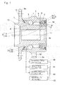
- the inner member 2 serving as a rotatable member is made up of a hub axle 9 having a hub flange 9a for mounting a wheel and a separate inner race 10 mounted fixedly on an outer periphery of an inboard end of a axle portion 9b of the hub axle 9.
- the raceway surfaces 4 in each of the rows are formed in the hub axle 9 and the inner race 10.
- a portion of the outer periphery surface at the inboard end of the hub axle 9 is radically inwardly stepped or decreased in diameter to define an inner race mounting area 12 and the inner race 10 is mounted on the inner race mounting surface 12.
- the hub axle 9 has a center bore 11 define therein.
- the hub flange 9a is provided with a plurality of press-fitting holes 15 for a hub mounting bolt (not shown) on an outer peripheral surface.
- a cylindrical pilot portion 13 for guiding a wheel and a braking part (not shown) is protruded to an outboard side in the vicinity of a root portion of the hub flange 9a of the hub axle 9.
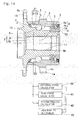
- the sensor unit 21 has a set of an external force calculator 40, a road action force calculator 41, a bearing preload calculator 42 and an abnormality determiner 43 as a device for processing the output thereof.
- Each of the devices 40 to 43 may be provided in an electronic circuit devices (not shown) such as a circuit board attached to the outer member 1 or the like of the bearing, or may be provided in an electric control unit (ECU) on board the motor vehicle.
- ECU electric control unit
- an adhesive agent may be used therebetween.
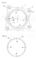
- a bolt 37 may be used for fitting the sensor fitting member 22 to the inner peripheral surface of the outer member 1.
- the sensor fitting member 22 is fitted to the outer member 1 by inserting the bolts 37 from a plurality of bolt insertion holes 26 provided in the peripheral surface of the outer member 1, and screwing the bolts 37 into thread holes 27 provided in the sensor fitting member 22.
- the sensor unit 21 is fixed to the inner peripheral surface of the outer member 1 through the contact fixing portions 22a, 22b of the sensor fitting member 22 so as to conform a longitudinal direction of the sensor fitting member 22 to the circumferential direction of the outer member 1.
- the contact fixing portions 22a, 22b are fixed to the outer member 1 by means of a bolt, an adhesive agent or the like. There exists a gap between the positions other than the contact fixing portions 22a, 22b of the sensor fitting member 22 and the inner peripheral surface of the outer member 1.
- the first contact fixing portion 22a, or any one of the contact fixing portions 22a and 22b, is fixed to the outer member 1 at an appropriate position in the circumferential direction at which the outer member 1 exhibits largest deformation in a radial direction by the load applied to the outer member 1.
- the second contact fixing portion 22b is fixed at another position at which the deformation in the radial direction is smaller than the appropriate position mentioned above.
- the first contact fixing portion 22a is fixed to a top position opposite to the road surface in a whole periphery of the outer member 1, and the second contact fixing portion 22b is fixed to a position which is below from the top position by several tens of degrees in the circumferential direction, for example, about 30 degrees to 45 degrees.
- the contact fixing portions 22a and 22b may be fixed to positions at which the direction of the strain in the radial direction caused by the external force applied to the outer member 1 or the action force between the tire and the road surface are inverted to each other.
- the directions of the deformation of the outer member 1 in the radial direction caused by the load in the axial direction applied to the contact point between the tire and the road surface are inverse to each other between a position in an upper half region (a position more than 90 degree above the road surface side position) of the outer member 1, and a position in a lower half region (a position closer to the road surface side).
- the directions of the deformation of the outer member 1 generated in both the contact fixing portions 22a and 22b become inversely different from each other.
- the first and second contact fixing portions 22a and 22b are fixed at the positions at which the directions of the strain in the radial direction of the outer member 1 are inversely different from each other, large deformation of the outer member 1 is transmitted to the sensor fitting member 22 due to the summation of the deformation of both the fixing portions 22a, 22b, thereby increasing the strain to be detected. Accordingly, the strain of the outer member 1 can be detected with a better sensitivity.
- the results of the FEM analysis and the experiment reveal that only the outboard side portion of the outer member 1 among the three positions above mentioned has the positive and negative directionalities in the strain depending on the directions of the load such as the external force or the action force, in both of the strains in the radial and circumferential directions of the outer member 1. Accordingly, in order to detect the directions of the load, it is recommendable to arrange the sensor unit 21 at the position in the outboard side in the outer member 1.
- the directions of the strain in the sensor unit 21 become opposite to each other at opposite sides in the circumferential direction with respect to the top position. Accordingly, even by fixing the first and second contact fixing portions 22a and 22b to the opposite sides with respect to the top position, the strain can sensitively be detected. Thus, the external force applied to the bearing for the wheel or the like can be detected on the basis of the value of the strain detected as mentioned above.
- the sensor unit 21 is provided only at one position of the outer member 1, however, the sensor unit 21 may be provided at two positions, for example, such as in a fourth embodiment shown in Fig. 9 .
- a cross sectional view of the bearing of the fourth embodiment appears identical with that shown in Fig. 1 .
- the two sensor units 21 enable the load to be detected more accurately.
- the sensor units 21 equal to or more than three provided at positions different to each other enable the load to be detected still further accurately.
- one of the contact fixing portions fixed to the inner periphery of the outer member 1 may be used in common with two sensor units 21, such as in a fifth embodiment shown in Figs. 10 and 11 .
- a circumferential groove 20 serving as a weakened portion having a lower rigidity than the surrounding area is formed on the inner periphery of the outboard side end of the outer member 1 at a position between the sealing device 7 and the raceway surface 3 in the axial direction.
- the sensor unit 21 is disposed at a suitable position in the circumferential groove 20. Since the outboard side end portion of the outer member 1 has no direct effect on the tire support, there is no problem with supporting the tire even if the rigidity of this portion is lowered.
- the sensor unit 21 includes the sensor fitting member 22 fitted to a bottom surface of the circumferential groove 20 and the strain sensor 23 attached to the sensor fitting member 22 so as to measure the strain of the sensor fitting member 22.
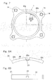
- the sensor fitting member 22 is formed as an approximately arcuate shape elongated in a circumferential direction along the bottom surface of the circumferential groove 20, as shown in Fig. 16 , and has opposite ends provided with the contact fixing portions 22a, 22b protruding radically outwardly of the arcuate and in an axial direction. Further, the cut-off portion 22c or a recessed portion open radically outwardly of the circular arc is formed at a center portion in a longitudinal direction of the sensor fitting member 22, and the strain sensor 23 is attached to an inner peripheral side of the circular arc or a surface opposite to the cut-off portion 22c.
- a transverse cross sectional shape of the sensor fitting member 22 is formed, for example, as a rectangular shape, however, may be formed as various shapes in addition thereto.
- the sensor unit 21 is fixed to the bottom surface of the circumferential grove 20 through the contact fixing portions 22a, 22b of the sensor fitting member 22.
- the contact fixing portions 22a, 22b are fixed to the bottom surface of the circumferential groove 20 by means of a bolt, an adhesive agent or the like.
- the sensor fitting member 22 is deformed in accordance with the deformation in the radial direction generated at the fixed position of the sensor fitting member 22 in the outer member 1.
- the strain generated in the sensor fitting member 22 becomes great, and as a result, a small strain of the stationary member can be detected by the sensor unit 21.
- the sensor fitting member 22 is formed as the arcuate shape and has the cut-off portion 22c at which the rigidity is lowered, the strain greater than the strain in the outer member 1 is generated in the sensor fitting member 22, and as a result, a small strain of the outer member 1 can accurately be detected by the strain sensor 23.
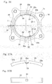
- Fig. 23 is a front elevational view showing an outer member of a sensor-equipped bearing for a wheel and a sensor unit in accordance with an eleventh embodiment of the present invention.
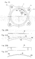
- the sensor fitting member 22 shown in Fig. 23 is formed by an arcuate shaped member having two flat plates 38 shown in Fig. 24 and an arcuate plate 25 shown in Fig. 25 .
- the flat plate 38 is a plate member elongated in a circumferential direction in which two concentric circular arcs around an axis of rotation of the bearing are set to conform with outer and inner peripheral edges, respectively.
- the flat plate 38 has opposite end portions 38a, 38b thereof somewhat protruding to an outer peripheral side, and has a center portion thereof provided with a cut-off portion 38c open to an inner peripheral side.
- the arcuate plate 25 is formed by a plate member which is curved in an arcuate shape corresponding to the outer peripheral edge of the flat plate 38, and is provided with a step so as to form opposite end portions 25a, 25b corresponding to the opposite end portions 38a, 38b of the flat plate 38, respectively.
- the sensor fitting member 22 in which two flat plates 38, 38 and the arcuate plate 25 are combined as a C-shaped cross sectional shape can be obtained as shown in Fig. 26 , specifically, by arranging two flat plates 38, 38 in parallel, arranging the arcuate plate 25 therebetween, and bonding the outer peripheral edge portion of the opposing surfaces of the flat plates 38, 38 to an axial end surface of the arcuate plate 25.
- the opposite end portions 38a, 38b of two flat plates 38 and the opposite end portions 25a, 25b of the arcuate plates 25 together form the contact fixing portions 22a, 22b of the sensor fitting member 22.
- the two flat plates 38, 38 and the arcuate plate 25 are obtained, for example, by means of a press working of a steel plate.
- the method for bonding the flat plates 38, 38 to the arcuate plate 25 is not particularly limited, and however, a welding or a brazing is suitable, for example.
- the strain sensor 23 is attached to a center portion of the inner peripheral surface of the arcuate plate 25 in the sensor fitting member 22 formed as mentioned above, that is, at the same position in the circumferential direction as the cut-off portion 38c of the flat plate 38.
- the sensor unit 21 is fixed to an inner peripheral surface of the outer member 1 at the contact fixing portions 22a, 22b of the sensor fitting member 22 by the bolt, the adhesive agent or the like. At the other positions than the contact fixing portions 22a, 22b of the sensor fitting member 22, there exists a gap between the sensor fitting member 22 and the inner peripheral surface of the outer member 1.
- the sensor unit 21 is arranged in such a manner that the one contact fixing portion 22a is fixed to the top position in a whole periphery of the outer member 1, and the other contact fixing portion 22b is fixed to a position below several tens of degrees from the top position.
- the portion at the top position in the whole periphery of the outer member 1 is most largely deformed in the radial direction by the load in the axial direction applied to the outer member 1, and at the portion below several tens of degrees from the top position, the deformation in the radial direction is less than that at the top position.
- the sensor fitting member 22 is deformed in accordance with the deformation in the radial direction generated at the fixed position of the sensor fitting member 22 in the outer member 1. Since the sensor-attached position in the sensor fitting member 22 corresponds to the position having the low rigidity in the circumferential direction corresponding to the cut-off portions 38c, 38c of the flat plates 38, 38, the strain greater than the strain of the outer member 1 is generated at the sensor-attached position, and as a result, the small strain of the outer member 1 can accurately be detected by the strain sensor 23.
- the structure of the sensor fitting member 22 that is, the structure having at least two contact fixing portions 22a, 22b to be fixed to the outer member 1 and having at least one cut-off portion 38c between the neighboring contact fixing portions 22a, 22b can be easily obtained by connecting two parallel flat plates 38, 38 having the cut-off portion 38c formed therein and the arcuate plate 25.
- the sensor fitting member 22 mentioned above is formed as the C-shaped cross sectional shape except a portion provided with the cut-off portion 38c, there is obtained an advantage that the sensor fitting member 22 can be simply manufactured as a shape lowering the rigidity of that portion provided with the cut-off portion 38c while keeping the whole rigidity high so as to generate a great strain.
- the flat plate 38 and the arcuate plate 25 can be easily and inexpensively manufactured by means of the press work of the steel plate. Two parallel flat plates 38 and the arcuate plate 25 separately prepared may be bonded together by any method, for example, a welding or a brazing.
- the two flat plates 38, 38 and the arcuate plate 25 separately prepared are bonded together to define the sensor fitting member 22 of a desired shape.
- a whole of them may be integrally molded by a press work to define the unitary sensor fitting member 22. If the sensor fitting member 22 is formed as the pressed unitary product, a working step can be reduced, and as a result, the sensor fitting member 22 can inexpensively be manufactured.
- the sensor fitting member 22 should be formed to have a shape in which a plastic deformation does not occur, even in the case that the conceivable maximum load is applied to the bearing.
- the sensor fitting member 22 in accordance with the embodiment mentioned above is formed as the C-shaped cross sectional shape to have a high whole rigidity.
- the sensor fitting member 22 may preferably be formed by adding a reinforcing member 36 shown in Fig. 27 to the sensor fitting member 22.
- the reinforcing member 36 is made of a plate member which is curved to have a arcuate shape corresponding to the shape of the inner peripheral edges of the flat plates 38, and a length in a circumferential direction thereof is set to a length from the inner peripheral edge end of the flat plate 38 to the cut-off portion 38c.
- Fig. 27 two reinforcing members 36 are employed in line.
- two flat plates 38, 38, one arcuate plate 25 and two reinforcing members 36, 36 are combined to have a rectangular cross sectional shape by bonding the outer peripheral edge portions of the opposing surfaces of two flat plates 38, 38 arranged in parallel and the axial end surface of the arcuate plate 25 together, and bonding the inner peripheral edge portions of the two flat plates 38, 38 and an end surfaces of the reinforcing members 36, 36 together.
- the sensor fitting member 22 mentioned above is structured such that a whole rigidity is remarkably improved.
- the sensor unit 21 Since the sensor unit 21 is arranged in the annular bearing space sealed by the sealing device 7, under normal conditions the sensor unit 21 is not affected by an external environment. However, under an adverse condition a corrosive gas or a corrosive liquid may intrude into the annular bearing space from small gaps between the outer member 1 or the inner member 2 and the sealing device 7. Such adverse condition may be encountered, when, for example, the wheel travels on a road covered with salt water or on a road including the salt water inside. In this case, the salt water intrudes into the annular bearing space.
- the corrosive gas or the corrosive liquid intrudes into the annular bearing space, the corrosive gas or the corrosive liquid preferentially reacts with the sacrificial anode 39 corresponding to the material having the electrochemically higher ionization tendency, thereby preventing the peripheral parts from being ionized, that is, being eluted.
- the strain sensor 23 and the sensor fitting member 22 can be protected from corrosion.
- the sensor fitting member 22 is completely covered with the sacrificial anode 39.
- the sacrificial anode member 39 made of a bulk material, attached to an arbitrary part of the sensor fitting member 22 is effective to prevent the corrosion of the strain sensor 23 and the sensor fitting member 22.
- the bulk material for example, the zinc, the zinc alloy or the like can be employed.
- sacrificial anode 39 is not limited to the structure in which the sensor unit 21 is attached to a part in the circumferential direction of the inner periphery of the outer member 1 such as the embodiment mentioned above, but the structure may be made, as shown in Fig 32 , such that the sensor fitting member 22 formed as a ring shape and mounted on the inner periphery of the outer member 1, and a plurality of strain sensors 23 are attached to the inner peripheral surface of the ring-shaped sensor fitting member 22. In this embodiment, four strain sensors 23 are attached to upper, lower, right and left sides of the sensor fitting member 22.
- the strains at a plurality of positions of the outer member 1 are detected by the strain sensors 23, and the load or the like applied to the wheel is detected from the output of a plurality of strain sensors 23. Accordingly, a detecting precision of the load or the like applied to the wheel is improved.
- the sensor fitting member 22 of the sensor unit 21 is formed as the ring shape
- the sensor fitting member 22 may be completely covered with the sacrificial anode 39 as shown in Fig. 33 , or the sacrificial anode member 39 may be attached to an arbitrary part of the sensor fitting member 22 as shown in Fig. 34 .
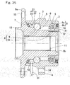
- Fig. 35 is a cross sectional view of the sensor-equipped bearing for the wheel in accordance with the fourteenth embodiment of the present invention.
- the inner peripheral surface of the outboard side end of the outer member 1 is provided with two sensor units 21 and a sensor signal processing circuit unit 45 electrically connected to the sensor units 21.
- the units 21, 21 and 45 are disposed at positions occupying a single position in an axial direction and attached to a portion positioned on the outboard side of the outboard side raceway surface 3, more specifically, between the outboard side raceway surface 3 and the sealing device 7.
- the sensor fitting member 22 is formed as an approximately arcuate shape elongated in a circumferential direction along the inner peripheral surface of the outer member 1, and has opposite ends provided with the contact fixing portions 22a, 22b protruding radically outwardly of the circular arc. Further, the cut-off portion 22c open radically outwardly of the circular arc is provided at a center portion of the sensor fitting member 22, and the strain sensor 23 is attached to a surface in the inner peripheral side of the circular arc positioned on surface opposite to the cut-off portion 22c.
- a horizontal cross sectional shape of the sensor fitting member 22 is formed, for example, as a rectangular shape, however, can be formed as various shapes.
- the two sensor units 21 are provided at two positions in the circumferential direction on the inner peripheral surface of the outer member 1.
- the first sensor unit 21-1 is attached in such a manner that one contact fixing portion 22a is fixed to the top position in the whole periphery of the outer member 1 and the other contact fixing portion 22b is fixed below several tens of degrees from the top position.
- the second sensor unit 21-2 is attached in such a manner that one contact fixing portion 22a is fixed to the bottom position in the whole periphery of the outer member 1, and the other contact fixing portion 22b is fixed above several tens of degree from the bottom portion.
- the positions at the top position and the bottom position in the whole periphery of the outer member 1 are most largely deformed in the radial direction by the load applied to the outer member 1.
- the portions at the position which is below several tens of degrees from the top position and at the position which is above several tens of degrees form the bottom position are deformed in the radial direction less than that at the top position and the bottom position.
- the sensor signal processing circuit unit 45 has a circular arc shaped housing 34, molded by a resin or the like and extending along the inner peripheral surface of the outer member 1.
- a circuit board 46 made of a glass epoxy or the like, on which a plurality of electric and electronic parts 28 are arranged is accommodated in the housing 34.
- a plurality of electric and electronic parts 28 includes an operational amplifier processing the output signal of the strain sensor 23, a resistance, a microcomputer or the like and a power supply part for driving the strain sensor 23.
- a sensor signal processing circuit for processing the output signal of the strain 23 is formed by the circuit board 46 and the electric and electronic parts 28.
- An end portion of the housing 34 has opposite ends provided with connection portions 29 to each other of which an end portion of a wiring 30 connected to the strain sensor 23 is bonded. Further, the housing 34 has a center portion to which a cable 31 for supplying an electric power to the sensor signal processing circuit and outputting the signal processed by the sensor signal processing circuit is connected.
- the sensor signal processing circuit unit 45 includes an external force calculator 40, a road force calculator 41, a bearing preload calculator 42 and an abnormality determiner 43.
- the one portion in the sensor fitting member 22 generates a strain greater than that generated in the stationary member due to a reduction of its rigidity, and as a result, the strain of the stationary member can be sensitively detected.
- the sensor signal processing circuit unit 45 is provided near the sensor unit 21, a wiring connecting the strain sensor 23 and the sensor signal processing circuit 45 is simplified, thereby facilitating wiring work, and further, a whole detecting system can be downsized in comparison with the case that the sensor signal processing circuit is provided in a position other than the bearing.
- the external force applied to the bearing or the like is detected by processing the output signal of the strain sensor 23 by the sensor signal processing circuit of the sensor signal processing circuit unit 45. Since the change of the strain is varied in accordance with the direction and the magnitude of the load, it is possible to calculate the external force applied to the bearing or the action force between the tire and the road surface by predetermining the relation between the stain and the load from the experiment or the simulation.
- the external force calculator 40 and the road surface action force calculator 41 respectively calculate the external force applied to the bearing and the action force between the tire and the road surface, on the basis of the output of the strain sensor 23, from the relation between the strain and the load which relation is predetermined from the experiment or the simulation as mentioned above.
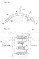
- Fig. 42 is a cross sectional view of the sensor-equipped bearing for the wheel in accordance with the sixteenth embodiment of the present invention.
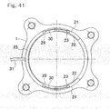
- Fig. 43 is a front elevational view of the sensor signal processing circuit unit 45.
- the sensor signal processing circuit unit 45 is provided integrally with various sensors 32 for detecting a state of the bearing for the wheel, in addition to the structure in the fourteenth embodiment.
- the various sensors 32 includes at least one of an acceleration sensor for detecting an acceleration of a rotation, a vibration sensor for detecting a vibration of the outer member 1, and a water ingredients detecting sensor for detecting whether or not a water ingredients exists in the annular bearing space.
- the sensor signal processing circuit unit 45 includes the various sensors 32 in addition to the sensor signal processing circuit having the external force calculator 40, the road surface action force calculator 41, the bearing preload amount calculator 42, and the abnormality determiner 43.
- the state of the bearing for the wheel is detected by the various sensors 32.
- the detected state of the bearing for the wheel can be used for the vehicle control of the motor vehicle, a service life evaluation, a maintenance determination and the like.
- the acceleration sensor is provided as the various sensors 32, it can be used for the traveling control of the motor vehicle.
- the vibration sensor is provided, the bearing service life can be estimated or determined on the basis of the vibration condition.
- the water ingredients detecting sensor it is possible to detect an amount of the water intruding into the annular bearing space through the sealing devices 7, 8, and a deterioration state of grease on the basis of the intruding water ingredients can be estimated.
- the wiring connecting the strain sensor 23 and the sensor signal processing circuit is simplified, and the wiring work can easily be carried out.
- the various sensors 32 at least one of the acceleration sensor, the vibration sensor and the water ingredients detecting sensor
- the wiring connecting the various sensors 32 and the sensor signal processing circuit unit 45 is not necessary.
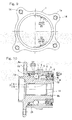
- Fig. 45 is a cross sectional view of the sensor-equipped bearing in accordance with the seventeenth embodiment of the present invention.
- the sensor signal processing circuit unit 45 is further provided integrally with a magnetic sensor 32 as the various sensor.
- the magnetic sensor 32 it is possible to employ, for example, a Hall element utilizing a Hall effect, a magnetic resistance element utilizing a magnetic resistance effect, and the like.
- the structure of the sensor unit 21 in the sensor-equipped bearing for the wheel in accordance with the seventeenth embodiment is the same structure as the sensor unit 21 in the third embodiment shown in Figs. 8A and 8B .
- a magnetic encoder 33 serving as a to-be-detected portion of the magnetic sensor 32 is attached to a position opposing to the magnetic sensor 32 in the outer peripheral surface of the inner member 2.
- the rotation sensor is formed by the magnetic sensor 32 and the magnetic encoder 33 to define a rotation sensor.
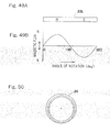
- the magnetic encoder 33 includes an annular core member 33a made of a metal, and a multipolar magnet 33b such as an annular rubber magnet provided on a surface of the core member 33a, as shown in Fig. 46 .
- the multipolar magnet 33b is magnetized in multiple poles in the circumferential direction, and magnetic poles N and S are alternately formed.
- the multipolar magnet 33b may be made of a plastic magnet or a sintered magnet in addition to the rubber magnet, or may be made of a ferrite material or the like.
- the sensor signal processing circuit includes the external force calculator 40, the road surface action force calculator 41, the bearing preload calculator 42, the abnormality determiner 43 and a rotating speed calculator 44. Functions of these devices will be mentioned later.
- the magnetic encoder 33 provided in the inner member 2 is relatively moved in the circumferential direction relative to the magnetic sensor 32.
- the magnetic sensor 32 outputs the output signal each time when the magnetic poles N and S alternately formed in the multipolar magnet 33b of the magnetic encoder 33 in the circumferential direction pass the opposing position of the magnetic sensor 32 on the basis of the relative movement of the magnetic encoder 33.
- the output signal of the magnetic sensor 32 is sequentially transmitted to the rotating speed calculator 44.
- the rotating speed calculator 44 counts the number of the output signal within a unitary time, and calculates the rotating speed of the wheel, in other words, a vehicle speed on the basis of the counted number of the output signal.
- the rotating speed so calculated as mentioned above can be used for the vehicle control of the motor vehicle.
- the magnetic sensor 32 is provided at two positions at which phase difference is not 180 degree, it is possible to detect a rotating direction in addition to the rotating speed. Even where the magnetic sensor 32 is provided at positions equal to or more than three, the rotating speed and the rotating direction can be detected.
- the magnetic encoder 33 may be applied to a rotation sensor particularly demanding a precision, for example, a rotation sensor used in an antilock brake system (ABS).
- the magnetic encoder serving as the to-be-detected portion of the magnetic sensor 32 may be structured such that one or more magnetic poles are arranged in the circumferential direction.
- Fig. 49 a magnitude of a magnetic flux generated from a to-be-detected portion or the encoder 33 varies in accordance with an angle of rotation of the rotatable member. Accordingly, it is possible to detect an absolute angle.
- Fig. 49A is a view showing by developing an annular magnet 33b in a linear shape
- Fig. 49B is a graph showing a magnetized state thereof.
- the sensor-equipped bearing in accordance with the seventeenth embodiment is structured such that the strain sensor 23 is attached to the sensor fitting member 22 fixed to the stationary member, and the magnetic sensor 32 is attached to the sensor signal processing circuit unit 45 fixed to the stationary member in the same manner, it is possible to compactly install the load sensor and the rotation sensor in the vehicle. Also, both the load and the rotation at one position can be detected by providing the magnetic sensor 32 serving as the rotation sensor in the sensor signal processing circuit unit 45. Since each of the sensor fitting member 22 and the sensor signal processing circuit unit 45 can be formed by a simple part attached to the stationary member, it is possible to obtain an excellent mass production so as to achieve a cost reduction by attaching the strain sensor 23 and the magnetic sensor 32 to the sensor fitting member 22.
- the sensor signal processing circuit unit 45 is provided near the sensor unit, the wiring connecting the strain sensor 23 and the sensor signal processing circuit 45 is simplified, and the wiring work is easily carried out. Further, since the magnetic sensor 32 is attached to the sensor signal processing circuit unit 45, the wiring to connect the magnetic sensor 32 and the sensor signal processing circuit unit 45 is not necessary. Accordingly, in comparison with the case in that the sensor signal processing circuit is provided in the portions other than the bearing, the whole of the detecting system can be downsized, and the wiring can be made simple.
- the sensor fitting member 22 is formed in a shape such that no plastic deformation occurs when the conceivable maximum load is applied to the bearing.
- the outer member 1 serves as the stationary member
- the present invention can be applied to the sensor-equipped bearing in which the inner member serves as the stationary member.
- the sensor fitting member is attached to a peripheral surface forming the outer periphery or the inner periphery of the inner member.
- each of the embodiments is described in the case of being applied to the third generation model bearing for the wheel, however, the present invention can be applied to a first or second generation model bearing for a wheel in which the bearing portion and the hub form the parts independent to each other, and a fourth generation model bearing for a wheel in which a part of the inner member is formed by an outer race of a constant velocity joint.
- the sensor-equipped bearing can be applied to a bearing for a driven wheel, and can be applied to a bearing for a wheel of a taper roller type of each of generations.
- the sensor-equipped bearing in the first aspect group of the present invention is structured such that in the basic construction mentioned above, the sensor fitting member is not plastically deformed at a time of being press-fitted to the stationary member.
- the ring member is not plastically deformed or the gap between the ring member the stationary member is not generated, even when the conceivable maximum value of the external force is applied to the bearing, or the action force between the tire and the road surface.
- the adhesive agent may be used for fixing the stationary member and the sensor fitting member, and the bolt may be used for this fixation.
- the elements are fixed by concomitantly using the adhesive agent and the bolt, it is possible to avoid the generation of the gap between the sensor fitting member and the stationary member, and as a result, the deformation of the stationary member can more accurately be transmitted to the sensor fitting member. Therefore, the strain of the stationary member can be more precisely detected.
- the abnormality determiner for determining whether or not the external force applied to the bearing or the action force between the tire and the road surface exceeds the predetermined tolerance value and outputting the abnormality signal in the case of determining that it exceeds the predetermined tolerance value.
- the sensor-equipped bearing included in the second aspect group of the present invention is structured such that in the basic construction mentioned above, the stationary member is provided with a sensor unit having the sensor fitting member and the strain sensor attached thereto, the sensor fitting member having at least two contact fixing portions fixed to the stationary member and at least one cut-off portion between the neighboring contact fixing portions, the strain sensor being attached to the cut-off portion.
- the first contact fixing portion of the contact fixing portions of the sensor fitting member is preferably attached to a position at which the deformation in the radial direction is significant in comparison with any other positions of the stationary member, induced by the external force applied to the stationary member or the action force between the tire and the road surface.
- the deformation of the stationary member in the radial direction caused by the external force or the action force is varied in accordance with the position in the circumferential direction.
- the deformation in the radial direction of the stationary member caused by the load in the axial direction applied to the contact point between the tire and the road surface becomes largest at nearest side and farthest side with respect to the road surface side and the road surface side, that is, a top position and a bottom position in the vertical direction in the stationary member.
- the first contact fixing portion is fixed to the position at which deformation in the radial direction may be observed more largely than any other positions in the stationary member
- the second contact fixing portion at which a smaller deformation is generated acts as a supporting point, and as a result, the largest deformation appears at the first contact fixing portion due to the deformation of the stationary member. Accordingly, at the sensor-arranged position in the sensor fitting member, a still larger strain is generated, and as a result, the strain of the stationary member can more sensitively be detected.
- the sensor unit is disposed at the outboard side position than the outboard raceway surface in the stationary member.
- only the outboard side portion of the stationary member has the positive and negative directionalities in the strain on the basis of the directions of the load such as the external force or the action force, in both of the strains in the radial and circumferential directions of the stationary member. Accordingly, in order to detect the directions of the load, it is recommendable to arrange the sensor unit at the position in the outboard side in the stationary member.
- the sensor unit is attached to the peripheral surface of the stationary member.
- the sensor unit may be attached to one of the peripheral surface and an end surface of the stationary member, however, in the case that the sensor unit is attached to the peripheral surface, the deformation of the stationary member tends to be accurately transmitted to the sensor fitting member, and as a result, the strain of the stationary member can sensitively be detected.
- the sensor-equipped bearing according to the third aspect group of the present invention is structured such that in the basic construction mentioned above, the stationary member is provided with a weakened portion in the vicinity of an end portion thereof and wherein a sensor unit having the sensor fitting member and the strain sensor is attached to the weakened portion, the sensor fitting member having at least two contact fixing portions fixed to the stationary member and at least one cut-off portion between the neighboring contact fixing portions, the strain sensor being attached to the cut-off portion.
- the sensor-equipped bearing according to the fourth aspect group of the present invention is structured such that in the basic construction mentioned above, the stationary member is provided with a sensor unit having the sensor fitting member and the strain sensor attached thereto, the sensor fitting member having at least two contact fixing portions fixed to the stationary member and at least one cut-off portion between the neighboring contact fixing portions, the strain sensor being attached to the cut-off portion and wherein a portion between the contact fixing portions of the sensor fitting member includes two flat plates parallel to each other and a arcuate plate connecting the flat plates together, each flat plate having the cut-off portion.
- the sensor fitting member is covered with the film of the sacrificial anode, corrosion of the strain sensor can be prevented. Further, since the strain sensor is placed adjacent the sacrificial anode, corrosion of the strain sensor can effectively be prevented. By means of plating technology, the film can easily be obtained.
- the sacrificial anode is made of a zinc or a zinc alloy. Since the zinc or the zinc alloy has the high ionization tendency, under the corrosive environment the zinc or the zinc alloy itself is preferentially ionized so as to be eluted thereby preventing the peripheral parts from being ionized, that is, being eluted. Accordingly, if the sacrificial anode is made of the zinc or the zinc alloy, it is possible to effectively prevent the sensor unit from being corroded in the case that the water or the salty liquid intrudes into the annular bearing space.
Applications Claiming Priority (9)
| Application Number | Priority Date | Filing Date | Title |
|---|---|---|---|
| JP2005229211A JP2007046635A (ja) | 2005-08-08 | 2005-08-08 | センサ付車輪用軸受 |
| JP2005240909A JP4925625B2 (ja) | 2005-08-23 | 2005-08-23 | センサ付車輪用軸受 |
| JP2005240911A JP2007056926A (ja) | 2005-08-23 | 2005-08-23 | センサ付車輪用軸受 |
| JP2005240912A JP2007057302A (ja) | 2005-08-23 | 2005-08-23 | センサ付車輪用軸受 |
| JP2005240908A JP4925624B2 (ja) | 2005-08-23 | 2005-08-23 | センサ付車輪用軸受 |
| JP2005240910A JP2007057301A (ja) | 2005-08-23 | 2005-08-23 | センサ付車輪用軸受 |
| JP2005250576A JP4879529B2 (ja) | 2005-08-31 | 2005-08-31 | センサ付車輪用軸受 |
| JP2005250577A JP2007064778A (ja) | 2005-08-31 | 2005-08-31 | センサ付車輪用軸受 |
| PCT/JP2006/315192 WO2007018072A1 (ja) | 2005-08-08 | 2006-08-01 | センサ付車輪用軸受 |
Publications (1)
| Publication Number | Publication Date |
|---|---|
| EP1921335A1 true EP1921335A1 (de) | 2008-05-14 |
Family
ID=37727260
Family Applications (1)
| Application Number | Title | Priority Date | Filing Date |
|---|---|---|---|
| EP06782070A Withdrawn EP1921335A1 (de) | 2005-08-08 | 2006-08-01 | Mit einem sensor ausgestattetes lager für ein rad |
Country Status (3)
| Country | Link |
|---|---|
| US (1) | US8167497B2 (de) |
| EP (1) | EP1921335A1 (de) |
| WO (1) | WO2007018072A1 (de) |
Cited By (3)
| Publication number | Priority date | Publication date | Assignee | Title |
|---|---|---|---|---|
| WO2009056334A1 (en) * | 2007-11-02 | 2009-05-07 | Aktiebolaget Skf | Combination of bearing component and sensor |
| EP1962073A4 (de) * | 2005-12-08 | 2016-03-16 | Ntn Toyo Bearing Co Ltd | Mit einem sensor ausgestattetes lager für ein rad |
| US20160161299A1 (en) * | 2014-12-08 | 2016-06-09 | Aktiebolaget Skf | Sensor device with mounting means |
Families Citing this family (29)
| Publication number | Priority date | Publication date | Assignee | Title |
|---|---|---|---|---|
| WO2008026305A1 (en) * | 2006-08-25 | 2008-03-06 | Ntn Corporation | Sensor-equipped bearing for wheel |
| CN101765519B (zh) * | 2007-07-31 | 2012-02-08 | Ntn株式会社 | 带有传感器的车轮用轴承 |
| JP5019988B2 (ja) * | 2007-07-31 | 2012-09-05 | Ntn株式会社 | センサ付車輪用軸受 |
| CN101868706B (zh) * | 2007-11-27 | 2013-08-28 | Ntn株式会社 | 带有传感器的车轮用轴承 |
| JP5153373B2 (ja) * | 2008-02-06 | 2013-02-27 | Ntn株式会社 | センサ付車輪用軸受 |
| JP5094457B2 (ja) * | 2008-02-15 | 2012-12-12 | Ntn株式会社 | センサ付車輪用軸受 |
| FR2927996B1 (fr) * | 2008-02-22 | 2011-09-02 | Roulements Soc Nouvelle | Systeme de mesure des deformations par mise en compression elastique d'une jauge |
| JP5274343B2 (ja) * | 2008-04-10 | 2013-08-28 | Ntn株式会社 | センサ付車輪用軸受 |
| EP2341327B1 (de) * | 2008-10-15 | 2013-09-18 | NTN Corporation | Mit sensor ausgestattetes radlager |
| MX2009011329A (es) * | 2008-10-21 | 2010-05-14 | Wabash National Lp | Ensamble acoplador de remolque que incluye un anodo de sacrificio. |
| WO2010052864A1 (ja) * | 2008-11-05 | 2010-05-14 | Ntn株式会社 | センサ付車輪用軸受 |
| WO2010055636A1 (ja) * | 2008-11-17 | 2010-05-20 | Ntn株式会社 | センサ付車輪用軸受 |
| JP5570308B2 (ja) * | 2009-09-25 | 2014-08-13 | セイコーインスツル株式会社 | 転がり軸受装置の製造方法 |
| DE112010004041T5 (de) | 2009-10-14 | 2012-11-29 | Ntn Corporation | Radlager mit Sensor |
| FR2953284A1 (fr) * | 2009-12-02 | 2011-06-03 | Movea Sa | Systeme et procede d'aide au conducteur d'un vehicule a entrainement biomecanique comprenant au moins une roue |
| JP5436191B2 (ja) * | 2009-12-21 | 2014-03-05 | Ntn株式会社 | インホイール型モータ内蔵センサ付き車輪用軸受装置 |
| JP5905681B2 (ja) * | 2011-08-23 | 2016-04-20 | Ntn株式会社 | 転がり軸受 |
| WO2013047346A1 (ja) | 2011-09-29 | 2013-04-04 | Ntn株式会社 | センサ付車輪用軸受装置 |
| JP5809927B2 (ja) * | 2011-10-28 | 2015-11-11 | Ntn株式会社 | インホイールモータ駆動装置 |
| US8678406B1 (en) * | 2012-09-28 | 2014-03-25 | GM Global Technology Operations LLC | Isolation sleeve |
| DE102012218619A1 (de) * | 2012-10-12 | 2014-04-17 | Schaeffler Technologies Gmbh & Co. Kg | Mediengeschmiertes Lager |
| GB2532928A (en) | 2014-11-27 | 2016-06-08 | Skf Ab | Sealing assembly and method for monitoring a sealing assembly |
| GB2532927A (en) * | 2014-11-27 | 2016-06-08 | Skf Ab | Sealing assembly and method for monitoring dynamic properties of a sealing assembly |
| GB2532762A (en) | 2014-11-27 | 2016-06-01 | Skf Ab | Load measurement device and method for determining load |
| AU2018338210A1 (en) | 2017-09-22 | 2020-04-09 | Consolidated Metco, Inc. | Wheel hub |
| JP6907993B2 (ja) * | 2018-04-19 | 2021-07-21 | トヨタ自動車株式会社 | 回転体の作用力検出装置 |
| MX2021005836A (es) | 2018-11-21 | 2021-07-15 | Cons Metco Inc | Aparato de extremo de la rueda con generador electrico. |
| DE102018221324A1 (de) * | 2018-12-10 | 2020-06-10 | Aktiebolaget Skf | Wälzlagereinheit |
| US11915530B2 (en) | 2019-10-09 | 2024-02-27 | Consolidated Metco, Inc. | Wheel end monitoring apparatus, fastener, and method |
Family Cites Families (46)
| Publication number | Priority date | Publication date | Assignee | Title |
|---|---|---|---|---|
| DE2911479C2 (de) | 1979-03-22 | 1983-09-29 | Lechler, Gerhard, Dr.-Ing., 1000 Berlin | Kraftmeßeinrichtung |
| JPS5923889B2 (ja) | 1979-05-28 | 1984-06-05 | 日本精工株式会社 | 圧延機におけるロ−ルのスラスト荷重の測定方法 |
| JPS59163531A (ja) | 1983-03-08 | 1984-09-14 | Ishikawajima Harima Heavy Ind Co Ltd | 軸受のスラスト荷重測定装置 |
| JPS63256832A (ja) | 1987-04-14 | 1988-10-24 | Tokyo Electric Co Ltd | ロ−ドセル |
| US5232932A (en) | 1992-05-21 | 1993-08-03 | R. J. Reynolds Tobacco Company | Method for treatment of neurodegenerative diseases |
| JPH0632735U (ja) * | 1992-09-30 | 1994-04-28 | エヌティエヌ株式会社 | センサ付転がり軸受 |
| JPH0961268A (ja) | 1995-08-25 | 1997-03-07 | Nippon Seiko Kk | 軸受用荷重測定装置 |
| JP2003530565A (ja) | 2000-04-10 | 2003-10-14 | ザ テイムケン コンパニー | 荷重を監視するためのセンサを備えたベアリングアセンブリ |
| US6535135B1 (en) * | 2000-06-23 | 2003-03-18 | The Timken Company | Bearing with wireless self-powered sensor unit |
| FR2812356B1 (fr) | 2000-07-28 | 2002-12-06 | Roulements Soc Nouvelle | Roulement comprenant au moins une zone de deformation elastique et ensemble de freinage le comprenant |
| NL1016756C2 (nl) | 2000-11-30 | 2002-05-31 | Skf Eng & Res Centre Bv | Meetelement voor het meten van radiale en/of axiale krachten op een lager. |
| JP2002340922A (ja) | 2001-01-25 | 2002-11-27 | Nsk Ltd | 車輪用回転検出装置 |
| DE10144269A1 (de) | 2001-09-08 | 2003-03-27 | Bosch Gmbh Robert | Sensorelement zur Erfassung einer physikalischen Messgröße zwischen tribologisch hoch beanspruchten Körpern |
| JP4352162B2 (ja) | 2001-12-03 | 2009-10-28 | 株式会社ジェイテクト | ドライブシャフトのトルク検出装置 |
| JP2003172347A (ja) * | 2001-12-06 | 2003-06-20 | Nsk Ltd | センサ付転動装置 |
| JP2004003601A (ja) | 2002-04-23 | 2004-01-08 | Nsk Ltd | センサ付転がり軸受ユニット |
| US7249528B2 (en) | 2002-05-17 | 2007-07-31 | Jtekt Corporation | Hub unit with sensor |
| JP2003336653A (ja) | 2002-05-17 | 2003-11-28 | Koyo Seiko Co Ltd | センサ付きハブユニット |
| DE10228412B4 (de) | 2002-06-25 | 2015-02-12 | Schaeffler Technologies Gmbh & Co. Kg | Radlager mit Sensoren |
| JP2004142577A (ja) * | 2002-10-24 | 2004-05-20 | Nsk Ltd | 車輪用転がり軸受ユニット |
| JP2004183684A (ja) | 2002-11-29 | 2004-07-02 | Nsk Ltd | 大形ころ軸受の荷重測定用構造 |
| JP2005037298A (ja) | 2003-07-17 | 2005-02-10 | Nsk Ltd | センサ付転動装置 |
| WO2005022104A1 (ja) | 2003-08-29 | 2005-03-10 | Jtekt Corporation | センサ付きハブユニット |
| JP3988702B2 (ja) * | 2003-08-29 | 2007-10-10 | 株式会社ジェイテクト | センサ付きハブユニット |
| US7628540B2 (en) | 2004-02-18 | 2009-12-08 | Ntn Corporation | Bearing device for wheel |
| JP2006010477A (ja) | 2004-06-25 | 2006-01-12 | Ntn Corp | 荷重センサ内蔵車輪用軸受装置 |
| JP2006077807A (ja) | 2004-09-07 | 2006-03-23 | Jtekt Corp | センサ付きハブユニット |
| JP2006266278A (ja) | 2005-03-22 | 2006-10-05 | Ntn Corp | センサ付車輪用軸受 |
| DE102005032222A1 (de) | 2005-07-09 | 2007-01-25 | Schaeffler Kg | Lageranordnung zur Lagerung wenigstens eines Maschinenelements an einer Stütze |
| JP2007057302A (ja) | 2005-08-23 | 2007-03-08 | Ntn Corp | センサ付車輪用軸受 |
| JP2007057258A (ja) | 2005-08-22 | 2007-03-08 | Ntn Corp | センサ付車輪用軸受 |
| EP1939598A1 (de) | 2005-08-22 | 2008-07-02 | Ntn Corporation | Mit einem sensor ausgestattetes lager für ein rad |
| JP2007057259A (ja) | 2005-08-22 | 2007-03-08 | Ntn Corp | センサ付車輪用軸受 |
| JP2007071280A (ja) | 2005-09-06 | 2007-03-22 | Ntn Corp | センサ付車輪用軸受 |
| JP2007078615A (ja) | 2005-09-16 | 2007-03-29 | Ntn Corp | センサ付車輪用軸受 |
| FR2893106B1 (fr) | 2005-11-09 | 2008-01-04 | Snr Roulements Sa | Roulement capteur de deformations comprenant au moins trois jauges de contrainte |
| US7882752B2 (en) | 2005-12-08 | 2011-02-08 | Ntn Corporation | Sensor-equipped bearing for wheel |
| JP4864441B2 (ja) | 2005-12-08 | 2012-02-01 | Ntn株式会社 | センサ付車輪用軸受 |
| JP5089041B2 (ja) | 2005-12-08 | 2012-12-05 | Ntn株式会社 | センサ付車輪用軸受 |
| WO2007105365A1 (ja) | 2006-03-08 | 2007-09-20 | Ntn Corporation | センサ付車輪用軸受 |
| JP2007292158A (ja) | 2006-04-24 | 2007-11-08 | Ntn Corp | センサ付車輪用軸受 |
| WO2008026305A1 (en) | 2006-08-25 | 2008-03-06 | Ntn Corporation | Sensor-equipped bearing for wheel |
| WO2008087858A1 (ja) | 2007-01-17 | 2008-07-24 | Ntn Corporation | センサ付車輪用軸受 |
| US8123411B2 (en) | 2007-03-27 | 2012-02-28 | Ntn Corporation | Sensor-equipped bearing for wheel |
| JP5019988B2 (ja) | 2007-07-31 | 2012-09-05 | Ntn株式会社 | センサ付車輪用軸受 |
| CN101765519B (zh) | 2007-07-31 | 2012-02-08 | Ntn株式会社 | 带有传感器的车轮用轴承 |
-
2006
- 2006-08-01 US US11/990,071 patent/US8167497B2/en not_active Expired - Fee Related
- 2006-08-01 WO PCT/JP2006/315192 patent/WO2007018072A1/ja active Application Filing
- 2006-08-01 EP EP06782070A patent/EP1921335A1/de not_active Withdrawn
Non-Patent Citations (1)
| Title |
|---|
| See references of WO2007018072A1 * |
Cited By (8)
| Publication number | Priority date | Publication date | Assignee | Title |
|---|---|---|---|---|
| EP1962073A4 (de) * | 2005-12-08 | 2016-03-16 | Ntn Toyo Bearing Co Ltd | Mit einem sensor ausgestattetes lager für ein rad |
| WO2009056334A1 (en) * | 2007-11-02 | 2009-05-07 | Aktiebolaget Skf | Combination of bearing component and sensor |
| WO2009056159A1 (en) * | 2007-11-02 | 2009-05-07 | Aktiebolaget Skf | Combination of bearing component and sensor |
| US8316723B2 (en) | 2007-11-02 | 2012-11-27 | Aktiebolaget Skf | Combination of bearing component and sensor |
| US20160161299A1 (en) * | 2014-12-08 | 2016-06-09 | Aktiebolaget Skf | Sensor device with mounting means |
| EP3031618A1 (de) * | 2014-12-08 | 2016-06-15 | Aktiebolaget SKF | Sensorvorrichtung mit montagemittel |
| US10041531B2 (en) * | 2014-12-08 | 2018-08-07 | Aktiebolaget Skf | Sensor device with mounting means |
| US10539179B2 (en) | 2014-12-08 | 2020-01-21 | Aktiebolaget Skf | Sensor device with mounting element |
Also Published As
| Publication number | Publication date |
|---|---|
| US20100135604A1 (en) | 2010-06-03 |
| US8167497B2 (en) | 2012-05-01 |
| WO2007018072A1 (ja) | 2007-02-15 |
Similar Documents
| Publication | Publication Date | Title |
|---|---|---|
| US8167497B2 (en) | Sensor-equipped bearing for wheel | |
| US7882752B2 (en) | Sensor-equipped bearing for wheel | |
| US7819026B2 (en) | Sensor-equipped wheel support bearing assembly | |
| EP1962074B1 (de) | Mit einem sensor ausgestattetes lager für ein rad | |
| EP2006653B1 (de) | Lager für ein rad mit sensor | |
| US8123411B2 (en) | Sensor-equipped bearing for wheel | |
| CN101238302B (zh) | 带有传感器的车轮用轴承 | |
| US8434947B2 (en) | Sensor-equipped bearing for wheel | |
| US8578791B2 (en) | Sensor-equipped bearing for wheel | |
| JP4925624B2 (ja) | センサ付車輪用軸受 | |
| EP1939598A1 (de) | Mit einem sensor ausgestattetes lager für ein rad | |
| JP2007155079A (ja) | センサ付車輪用軸受 | |
| JP2007057300A (ja) | センサ付車輪用軸受 | |
| JP2007057302A (ja) | センサ付車輪用軸受 | |
| JP2007078615A (ja) | センサ付車輪用軸受 | |
| JP2007057259A (ja) | センサ付車輪用軸受 | |
| JP4879529B2 (ja) | センサ付車輪用軸受 | |
| JP2007064778A (ja) | センサ付車輪用軸受 | |
| JP2007056926A (ja) | センサ付車輪用軸受 | |
| JP2007071652A (ja) | センサ付車輪用軸受 | |
| JP2007057301A (ja) | センサ付車輪用軸受 | |
| JP4493569B2 (ja) | センサ付車輪用軸受 | |
| JP2007078129A (ja) | センサ付車輪用軸受 | |
| JP2007071628A (ja) | センサ付車輪用軸受 | |
| WO2006100881A1 (ja) | センサ付車輪用軸受 |
Legal Events
| Date | Code | Title | Description |
|---|---|---|---|
| PUAI | Public reference made under article 153(3) epc to a published international application that has entered the european phase |
Free format text: ORIGINAL CODE: 0009012 |
|
| 17P | Request for examination filed |
Effective date: 20080306 |
|
| AK | Designated contracting states |
Kind code of ref document: A1 Designated state(s): DE FR |
|
| DAX | Request for extension of the european patent (deleted) | ||
| RBV | Designated contracting states (corrected) |
Designated state(s): DE FR |
|
| STAA | Information on the status of an ep patent application or granted ep patent |
Free format text: STATUS: THE APPLICATION HAS BEEN WITHDRAWN |
|
| 18W | Application withdrawn |
Effective date: 20130618 |