EP2732684B1 - Set top box having snap-in heat sink and smart card reader with a hold down for retaining the heat sink - Google Patents
Set top box having snap-in heat sink and smart card reader with a hold down for retaining the heat sink Download PDFInfo
- Publication number
- EP2732684B1 EP2732684B1 EP12748289.1A EP12748289A EP2732684B1 EP 2732684 B1 EP2732684 B1 EP 2732684B1 EP 12748289 A EP12748289 A EP 12748289A EP 2732684 B1 EP2732684 B1 EP 2732684B1
- Authority
- EP
- European Patent Office
- Prior art keywords
- heat sink
- bottom frame
- hold down
- circuit board
- electronic device
- Prior art date
- Legal status (The legal status is an assumption and is not a legal conclusion. Google has not performed a legal analysis and makes no representation as to the accuracy of the status listed.)
- Active
Links
- 230000013011 mating Effects 0.000 claims description 9
- 230000004888 barrier function Effects 0.000 description 5
- 230000005855 radiation Effects 0.000 description 2
- 239000010963 304 stainless steel Substances 0.000 description 1
- 229910000589 SAE 304 stainless steel Inorganic materials 0.000 description 1
- 230000000712 assembly Effects 0.000 description 1
- 238000000429 assembly Methods 0.000 description 1
- 230000017525 heat dissipation Effects 0.000 description 1
- 239000011810 insulating material Substances 0.000 description 1
- 239000000463 material Substances 0.000 description 1
- 239000002184 metal Substances 0.000 description 1
- 238000013021 overheating Methods 0.000 description 1
- 239000012858 resilient material Substances 0.000 description 1
Images


Classifications
-
- H—ELECTRICITY
- H05—ELECTRIC TECHNIQUES NOT OTHERWISE PROVIDED FOR
- H05K—PRINTED CIRCUITS; CASINGS OR CONSTRUCTIONAL DETAILS OF ELECTRIC APPARATUS; MANUFACTURE OF ASSEMBLAGES OF ELECTRICAL COMPONENTS
- H05K7/00—Constructional details common to different types of electric apparatus
- H05K7/02—Arrangements of circuit components or wiring on supporting structure
- H05K7/12—Resilient or clamping means for holding component to structure
-
- H—ELECTRICITY
- H05—ELECTRIC TECHNIQUES NOT OTHERWISE PROVIDED FOR
- H05K—PRINTED CIRCUITS; CASINGS OR CONSTRUCTIONAL DETAILS OF ELECTRIC APPARATUS; MANUFACTURE OF ASSEMBLAGES OF ELECTRICAL COMPONENTS
- H05K7/00—Constructional details common to different types of electric apparatus
- H05K7/20—Modifications to facilitate cooling, ventilating, or heating
- H05K7/2039—Modifications to facilitate cooling, ventilating, or heating characterised by the heat transfer by conduction from the heat generating element to a dissipating body
- H05K7/20436—Inner thermal coupling elements in heat dissipating housings, e.g. protrusions or depressions integrally formed in the housing
- H05K7/2049—Pressing means used to urge contact, e.g. springs
-
- H—ELECTRICITY
- H05—ELECTRIC TECHNIQUES NOT OTHERWISE PROVIDED FOR
- H05K—PRINTED CIRCUITS; CASINGS OR CONSTRUCTIONAL DETAILS OF ELECTRIC APPARATUS; MANUFACTURE OF ASSEMBLAGES OF ELECTRICAL COMPONENTS
- H05K7/00—Constructional details common to different types of electric apparatus
- H05K7/20—Modifications to facilitate cooling, ventilating, or heating
- H05K7/2039—Modifications to facilitate cooling, ventilating, or heating characterised by the heat transfer by conduction from the heat generating element to a dissipating body
Definitions
- the invention relates to a set top box, and more particularly, a set top box having a hold down for retaining a heat sink.
- Document US 2010 097 768 A1 describes an electronic apparatus includes a housing, a circuit board contained in the housing, an integrated-circuit component mounted on the circuit board, a member for heat radiation opposed to the integrated-circuit component and thermally connected to the integrated-circuit component, a sheet metal member which fixes the member for heat radiation, and an electronic component mounted on the circuit board.
- Document WO 2010 118971 A1 describes a housing for one electronic card comprising two lateral guides suitable for engaging with slides arranged on the inner surfaces of an electronic rack, including two half-shells , clamped against one another at the lateral guides, the bottom half-shell comprising at least one support area forming a recess for an electronic card, the housing also including a means for clamping each electronic card in each corresponding recess, and for clamping at least one heat sink against the top surface of at least one electronic card, the frame having the function of absorbing mechanical constraints associated with the electronic cards housed by the housing, the cover having the function of ensuring good thermal conductivity enabling the heat produced by an electronic card to be dissipated during the operation thereof.
- Document US 7 385 822 B1 describes a clip assembly for mounting a heat sink on a printed circuit board includes a closed annular positioning portion interferingly engaging with the heat sink, a securing portion secured to the positioning portion.
- the securing portion has a pressing member extending through an opening defined in the positioning portion for resiliently abutting against the heat sink, and two arms extending from free ends of the pressing member with a pair of hooks formed at distal portions of the two arms for engaging with the printed circuit board.
- Thermal management remains a significant challenge in set top boxes. With the introduction of more components such as smart card readers and increased functionalities, which tend to produce more heat, the need for an improved thermal management system exists.
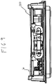
- a circuit board 5 is housed within a top cover 7 of a set top box 1.
- a thermal barrier 4 is positioned between the circuit board 5 and a bottom frame 2.
- a smart card reader 3 is connected to the circuit board 5 through an aperture 8 in the thermal barrier 4.
- the set top box 1 has internal components including the smart card reader 3, the thermal barrier 4, the circuit board 5, and a heat sink 6 that contacts the circuit board 5 and is positioned between the bottom frame 2 and the top cover 7.
- the thermal barrier 4 includes a thermal insulating material that preferably has substantially the same profile as the circuit board 5 or a profile that is at least 80% of the area profile of the circuit board 5. The thermal barrier 4 keeps the smart card reader 3 and other components under the circuit board 5 from overheating, in part, by preventing heat from transferring from the circuit board 5 and the components thereon.
- the heat sink 6 is a heat dissipating feature that removes heat from the circuit board 5.
- the heat sink 6 has a top plan profile that completely covers the circuit board 5 or substantially covers the circuit board 5 such that at least 80% of the circuit board 5 is covered.
- the heat sink 6 may include a thermal pad 9.
- the heat sink 6 is a contoured plate that has a generally planar periphery 52 and a recessed feature such as a central depression 53 into a plane of the planar periphery 52, wherein the planar periphery 52 preferably surrounds the central depression 53.
- the central depression 53 has side walls extending from the planar periphery 52 and forming an obtuse angle therewith.
- the central depression 53 has a flat bottom that is designed to contact the circuit board 5, the heat generating components on the circuit board 5, and/or the thermal pad 9.
- the heat sink 6 has vertical extensions 64 at the outer edges of the planar periphery 52 that are perpendicular to the planar periphery 52 and that extend over the circuit board 5 and contact the bottom frame 2 or vertically extending portions 62 of the bottom frame 2.
- the heat sink 6 attaches to the bottom frame 2 through slots and clips formed on these elements.
- the vertically extending portions 62 extend from the bottom frame 2 and have receiving slots 61 that are designed to receive clips 71 formed on the vertical extensions 64 of the heat sink 6.
- the vertically extending portions 62 may be plastic components, and as such, allow the heat sink clips 71 to elastically snap into the slots 61, thereby securing the heat sink 6 to the bottom frame 2.
- the arrow indicates how the heat sink clips 71 are pressed downward onto the bottom frame slots 61.
- Figure 3 is a perspective view of interior components of the set top box 1.
- the set top box 1 may include a second central depression 90 that contacts a secondary thermal pad 99 associated with the smart card reader 3.
- the bottom frame 2 may include a smart card access slot 91 below the circuit board 5 and one of the vertical extensions 64 of the heat sink 6.
- the slot 91 may also be between the vertically extending portions 62 of the bottom frame 2.
- the second central depression 90 thermally communicates with the smart card reader 3 through an aperture 8 in the circuit board 5 or the secondary thermal pad 99 through the circuit board 5.
- the set top box 1 described in Figures 1-3 further includes a hold down 130 to secure the heat sink 6 against the circuit board 5.
- Figure 4 shows an exploded view of the set top box 1 with the hold down 130.
- the hold down 130 includes a frame that defines a perimeter.
- the hold down 130 may be a rectangular frame that generally matches the shape of the heat sink 6.
- the perimeter of the hold down 130 includes retainers 103 arranged at the ends of the hold down 130.
- the retainers 103 are shaped to match and engage mating locations provided on at least the bottom frame 2.
- the heat sink 6 may also include mating locations for the retainers 103.
- the hold down 130 is preferably constructed from a rigid flexible material, such as a wire or multiple wires, preferably 304 stainless steel, that may extend diagonally to bias the heat sink 6 downwards against the thermal pad 9 and to provide contact between the circuit board 5, the thermal pad 9, and the central depression 53 of the heat sink 6 for proper thermal dissipation.
- the wires may cross each other such that one wire includes a bent portion that extends below the other wire.
- the region where the hold down components or wires cross can be centralized to be over the central depression and can inside the central depression.
- the hold down or wires can be applied to the prior art assemblies to enhance heat transfer to the heatsink.
- the bottom surface of the central depression 53 and the circuit board 5 contact the thermal pad 9 on opposite sides and sandwich the thermal pad 9 between them.
- the hold down 130 improves the surface contact among these components.
- the hold down 130 may be formed from a resilient material.
- the hold down 130 is preferably dimensioned such that the hold down 130 is tensioned when installed and exerts a biasing force across the top of the heat sink 6 or at a specific location on the heat sink 6 after the retainers 103 of the hold down 130 engage the mating locations of the bottom frame 2 and the heat sink 6.
- the top surface of the heat sink 6 may define a longitudinal plane and the frame of the hold down 130 may extend in this plane or in a parallel plane. As shown in Figure 9 , when the hold down 130 engages the mating locations of the bottom frame 2 and the heat sink 6 and the hold down 130 engages the top surface of the heat sink 6, the heat sink 6 and the hold down 130 bows in the downward direction away from the initial plane or planes.
- the hold down 130 may also include end portions that rise vertically above the longitudinal plane of the heat sink 6. The extent of the hold down 130 between the end portions may bow downwardly to apply force to the heat sink 6.
- the hold down 130 may include a central portion that extends downward into the central depression 53 of the heat sink 6 and along the inner contours of the central depression 53 such that the hold down 130 is in further contact with the heat sink 6 and movement is further reduced. As compared to existing set top boxes, the hold down 130 allows for a thinner thermal pad 9 to be used because of the biasing force from the hold down 130 on the heat sink 6.
- Figures 5-8 show various features of the set top box 1 and the hold down 130.
- the retainers 103 of the hold down 130 engage slots 92 formed on the vertically extending portions 62 of the bottom frame 2 and slots 120 formed on the vertical extensions 64 of the heat sink 6.
- Figure 5 shows an assembled cutaway view of the set top box 1 with the hold down 130 pressing the central depression 53 of the heat sink 6 downward onto the thermal pad 9 on the circuit board 5.
- the heat sink 6 may include grooves 67 that are sufficiently deep to receive the hold down 130 and prevent the hold down 130 from protruding above the heat sink 6.
- the grooves 67 allow the vertical height of the set top box 1 to remain the same as compared to set top boxes without a hold down.
- the vertical extensions 64 of the heat sink 6 may also include cut out portions 140 that are shaped to receive portions of the hold down 130.
- Figure 6 is sectional side view of the set top box 1 and illustrates the improved contact of the bottom surface of the central depression 53 with the thermal pad 9 as compared to existing set top boxes.
- Figure 7 illustrates the slots 61 on the bottom frame 2 for receiving the clips 71 of the heat sink 6, and the slots 92 for receiving the retainers 103 at the ends of the hold down 130.
- Figure 8 shows alternative embodiments of the retainers 103 of the hold down 130 and illustrates the retainers 103 may include any suitable end which secures the hold down 130 with the mating locations of the bottom frame 2 and the heat sink 6.
- the retainers 103 may include ends 132 with U-shaped or V-shaped inward contours that engage the slots 92 of the bottom frame 2 and the slots 120 of the heat sink 6.
- the retainers 103 may alternatively include ends 134 with a first vertical portion, a lower horizontal portion, and second vertical portion which engage the slots 92, 120 of the bottom frame 2 and heat sink 6. As noted above, the ends 132, 134 may engage the slots 92, 120 in such a way to tension the hold down 130.
Landscapes
- Engineering & Computer Science (AREA)
- Microelectronics & Electronic Packaging (AREA)
- Physics & Mathematics (AREA)
- Thermal Sciences (AREA)
- Cooling Or The Like Of Electrical Apparatus (AREA)
Applications Claiming Priority (2)
| Application Number | Priority Date | Filing Date | Title |
|---|---|---|---|
| US201161572314P | 2011-07-14 | 2011-07-14 | |
| PCT/US2012/046466 WO2013009982A1 (en) | 2011-07-14 | 2012-07-12 | Set top box having snap-in heat sink and smart card reader with a hold down for retaining the heat sink |
Publications (2)
| Publication Number | Publication Date |
|---|---|
| EP2732684A1 EP2732684A1 (en) | 2014-05-21 |
| EP2732684B1 true EP2732684B1 (en) | 2022-01-12 |
Family
ID=46690687
Family Applications (1)
| Application Number | Title | Priority Date | Filing Date |
|---|---|---|---|
| EP12748289.1A Active EP2732684B1 (en) | 2011-07-14 | 2012-07-12 | Set top box having snap-in heat sink and smart card reader with a hold down for retaining the heat sink |
Country Status (7)
| Country | Link |
|---|---|
| US (1) | US9485884B2 (zh) |
| EP (1) | EP2732684B1 (zh) |
| JP (1) | JP5792386B2 (zh) |
| KR (1) | KR20140041701A (zh) |
| CN (1) | CN103703875B (zh) |
| BR (1) | BR112014000762A2 (zh) |
| WO (1) | WO2013009982A1 (zh) |
Families Citing this family (17)
| Publication number | Priority date | Publication date | Assignee | Title |
|---|---|---|---|---|
| JP2015504240A (ja) * | 2011-11-21 | 2015-02-05 | トムソン ライセンシングThomson Licensing | ヒートシンクを保持する留め具 |
| US9220186B2 (en) * | 2012-02-10 | 2015-12-22 | Cooper Technologies Company | Integrated direct couple heat sink and shock/vibration protection |
| US9007773B2 (en) * | 2012-08-31 | 2015-04-14 | Flextronics Ap, Llc | Housing unit with heat sink |
| TW201444460A (zh) * | 2013-05-14 | 2014-11-16 | Hon Hai Prec Ind Co Ltd | 散熱器組合 |
| CN104253096A (zh) * | 2013-06-27 | 2014-12-31 | 鸿富锦精密工业(深圳)有限公司 | 电子设备 |
| USD773394S1 (en) * | 2015-05-07 | 2016-12-06 | General Electric Company | Enclosure for electronic device |
| US9760742B2 (en) | 2015-06-26 | 2017-09-12 | Echostar Technologies L.L.C. | Dual purpose press-bar and heat sink for high data transfer integrated circuit card reader |
| CN105392310B (zh) * | 2015-10-30 | 2019-03-26 | 安徽亿联智能有限公司 | 一种机顶盒 |
| JP6274196B2 (ja) * | 2015-12-16 | 2018-02-07 | 株式会社オートネットワーク技術研究所 | 電気接続箱 |
| CN106792028A (zh) * | 2016-12-29 | 2017-05-31 | 重庆金鑫智慧科技有限公司 | 一种基于物联网的机顶盒控制智能家居系统 |
| US10043043B1 (en) | 2017-02-07 | 2018-08-07 | DISH Technologies L.L.C. | Integrated circuit card reader with improved heat dissipation |
| US10757836B2 (en) * | 2017-12-04 | 2020-08-25 | Channell Commercial Corporation | Solar/heat shield for pedestal housings used with active electronic devices and/or heat sensitive components |
| EP3684154B1 (en) * | 2019-01-21 | 2024-03-06 | Aptiv Technologies Limited | Thermally conductive insert element for electronic unit |
| DE102019134098B4 (de) * | 2019-12-12 | 2023-11-23 | Avl Software And Functions Gmbh | Kühlrichtungsorientierte Kühleinrichtung |
| DE102019134118A1 (de) * | 2019-12-12 | 2021-06-17 | Avl Software And Functions Gmbh | Fahrzeugelektronikbaugruppenvorrichtung mit kombinierbaren Elektronikbaugruppen |
| TWI734521B (zh) * | 2020-06-12 | 2021-07-21 | 啓碁科技股份有限公司 | 具有散熱結構之電子裝置 |
| US20230345675A1 (en) * | 2022-04-26 | 2023-10-26 | Dish Network, L.L.C. | Electronic assembly having thermal pad with polymer layer |
Citations (1)
| Publication number | Priority date | Publication date | Assignee | Title |
|---|---|---|---|---|
| US7385822B1 (en) * | 2007-06-11 | 2008-06-10 | Fu Zhun Industry (Shen Zhen) Co., Ltd. | Clip assembly |
Family Cites Families (94)
| Publication number | Priority date | Publication date | Assignee | Title |
|---|---|---|---|---|
| DE3442902C1 (de) | 1984-11-24 | 1986-06-12 | Daimler-Benz Ag, 7000 Stuttgart | Leuchteneinheit fuer Kraftfahrzeuge |
| US4887147A (en) | 1987-07-01 | 1989-12-12 | Digital Equipment Corporation | Thermal package for electronic components |
| JPH02307182A (ja) | 1989-05-23 | 1990-12-20 | Hitachi Maxell Ltd | Icカードリーダ・ライタ |
| JP2758283B2 (ja) | 1991-06-17 | 1998-05-28 | 株式会社東芝 | ハードディスクパックの脱着機構 |
| US6850252B1 (en) | 1999-10-05 | 2005-02-01 | Steven M. Hoffberg | Intelligent electronic appliance system and method |
| JPH06227553A (ja) | 1993-01-28 | 1994-08-16 | Yazaki Corp | ロック構造 |
| US5620242A (en) | 1993-04-19 | 1997-04-15 | Motorola, Inc. | Portable radio battery latch |
| JP3251734B2 (ja) | 1993-08-18 | 2002-01-28 | 株式会社日立テレコムテクノロジー | 電子装置の筐体構造 |
| JPH0786471A (ja) | 1993-09-20 | 1995-03-31 | Hitachi Ltd | 半導体モジュ−ル |
| US5667397A (en) | 1994-12-01 | 1997-09-16 | The Whitaker Corporation | Smart card connector |
| US5917236A (en) | 1995-12-08 | 1999-06-29 | Hewlett-Packard Company | Packaging system for field effects transistors |
| US5691878A (en) * | 1996-02-02 | 1997-11-25 | Motorola, Inc. | Snap-lockable housing for fluorescent lamp ballasts |
| JP3776169B2 (ja) | 1996-06-13 | 2006-05-17 | 任天堂株式会社 | 電子機器の放熱構造 |
| JPH1065385A (ja) | 1996-08-21 | 1998-03-06 | Mitsubishi Electric Corp | 基板ケース構造体 |
| JPH10154390A (ja) | 1996-11-20 | 1998-06-09 | Nippon Columbia Co Ltd | ディスク再生装置 |
| US6049469A (en) | 1997-08-20 | 2000-04-11 | Dell Usa, L.P. | Combination electromagnetic shield and heat spreader |
| US7082033B1 (en) | 1998-02-13 | 2006-07-25 | Micron Technology, Inc. | Removing heat from integrated circuit devices mounted on a support structure |
| JP3597368B2 (ja) | 1998-02-16 | 2004-12-08 | アルプス電気株式会社 | 電子機器 |
| US6021044A (en) | 1998-08-13 | 2000-02-01 | Data General Corporation | Heatsink assembly |
| JP2000269675A (ja) | 1999-03-19 | 2000-09-29 | Sony Corp | 放熱装置およびセット・トップ・ボックス |
| JP2000269671A (ja) | 1999-03-19 | 2000-09-29 | Toshiba Corp | 電子機器 |
| US6411522B1 (en) | 1999-04-01 | 2002-06-25 | Western Digital Ventures, Inc. | Integrated computer module with EMI shielding plate |
| JP3982941B2 (ja) | 1999-04-12 | 2007-09-26 | 富士通株式会社 | 記憶装置 |
| US6382995B1 (en) | 1999-05-20 | 2002-05-07 | Itt Manufacturing Enterprises, Inc | Smart card connector with retain and eject means |
| DE69937103T2 (de) | 1999-06-08 | 2008-06-12 | Molex Inc., Lisle | Tragbare Chipkarten-Leseanordnung |
| EP1192581A1 (en) | 1999-07-02 | 2002-04-03 | 3M Innovative Properties Company | Smart card reader |
| JP2001147061A (ja) | 1999-09-08 | 2001-05-29 | Sega Corp | 冷却装置を有する電子機器 |
| GB2355017B (en) | 1999-09-23 | 2001-09-12 | Lorenzo Battisti | Porous element |
| US6212074B1 (en) | 2000-01-31 | 2001-04-03 | Sun Microsystems, Inc. | Apparatus for dissipating heat from a circuit board having a multilevel surface |
| US6317325B1 (en) * | 2000-02-23 | 2001-11-13 | Lucent Technologies Inc. | Apparatus for protecting circuit pack assemblies from thermal and electromagnetic effects |
| JP3923703B2 (ja) | 2000-03-29 | 2007-06-06 | ローム株式会社 | 放熱手段を有するプリント配線板 |
| JP2001358482A (ja) | 2000-04-14 | 2001-12-26 | Matsushita Refrig Co Ltd | 放熱モジュール |
| FR2809871B1 (fr) | 2000-06-05 | 2002-07-19 | Itt Mfg Entpr S Inc | Connecteur electrique a lames de contact perfectionnees pour le raccordement d'une carte a circuit(s) integre(s) |
| US20020051338A1 (en) | 2000-07-27 | 2002-05-02 | Lixin Jiang | Acoustic enclosure for an air cooled hard disk drive |
| DE10051159C2 (de) | 2000-10-16 | 2002-09-19 | Osram Opto Semiconductors Gmbh | LED-Modul, z.B. Weißlichtquelle |
| US6524361B1 (en) | 2000-10-26 | 2003-02-25 | Hubbell Incorporated | Micro-porous filter |
| JP2002134970A (ja) | 2000-10-26 | 2002-05-10 | Denso Corp | 電子制御装置 |
| EP1248507A1 (de) | 2001-04-04 | 2002-10-09 | Siemens Aktiengesellschaft | Hochfrequenzmodul eines Audio-Gerätes mit optimierter Wärmeableitung |
| JP2002324989A (ja) | 2001-04-26 | 2002-11-08 | Murata Mach Ltd | 印刷回路基板の放熱構造 |
| JP4057796B2 (ja) | 2001-07-03 | 2008-03-05 | 株式会社東芝 | 非水電解質空気電池 |
| US6881077B2 (en) * | 2002-07-22 | 2005-04-19 | Siemens Vdo Automotive Corporation | Automotive control module housing |
| US6735085B2 (en) | 2002-08-15 | 2004-05-11 | Hon Hai Precision Ind. Co., Ltd. | Foldable retention device for land grid array connector assembly |
| JP2004186294A (ja) | 2002-12-02 | 2004-07-02 | Denso Corp | 電子装置 |
| JP4039316B2 (ja) | 2003-06-09 | 2008-01-30 | 株式会社明電舎 | 電子機器の冷却構造 |
| JP2005005424A (ja) | 2003-06-11 | 2005-01-06 | Matsushita Electric Ind Co Ltd | 電磁波シールドパネルとこれを用いた保温保冷機器、電子機器、衣料用品、及び住宅部材 |
| EP1508916B1 (en) | 2003-08-07 | 2008-03-05 | Harman Becker Automotive Systems GmbH | Apparatus for cooling semiconductor devices attached to a printed circuit board |
| EP1511314B1 (en) | 2003-08-29 | 2009-01-07 | Thomson Licensing | System and method for smart card reader activation |
| EP1511313A1 (en) | 2003-08-29 | 2005-03-02 | Thomson Licensing S.A. | Control device, smart card reading activation device and associated products |
| US7203065B1 (en) | 2003-11-24 | 2007-04-10 | Ciena Corporation | Heatsink assembly |
| US20050128710A1 (en) | 2003-12-15 | 2005-06-16 | Beiteimal Abdlmonem H. | Cooling system for electronic components |
| TWI256192B (en) | 2004-04-15 | 2006-06-01 | Acbel Polytech Inc | Power adapter with heat sink device |
| FR2871022B1 (fr) | 2004-05-25 | 2006-11-03 | Valeo Electronique Sys Liaison | Boitier pour circuits electriques ou electroniques |
| GB0413340D0 (en) | 2004-06-15 | 2004-07-21 | Pace Micro Tech Plc | Improvements to electrical apparatus |
| US7215551B2 (en) | 2004-09-29 | 2007-05-08 | Super Talent Electronics, Inc. | Memory module assembly including heat sink attached to integrated circuits by adhesive |
| FR2875917B3 (fr) | 2004-09-29 | 2007-01-05 | Alvaro Lemos | Dispositif d'aeration pliable pour la protection de micro-ordinateurs portables |
| TWI247574B (en) | 2004-11-30 | 2006-01-11 | Silicon Integrated Sys Corp | Heat dissipation mechanism for electronic device |
| US7791874B2 (en) | 2004-12-30 | 2010-09-07 | Microsoft Corporation | Removable module for a console |
| JP2006229046A (ja) | 2005-02-18 | 2006-08-31 | Toshiba Corp | 電子機器の放熱装置及び放熱方法 |
| JP4445409B2 (ja) | 2005-02-23 | 2010-04-07 | 株式会社東芝 | 電子機器の放熱装置 |
| US7158380B2 (en) | 2005-03-25 | 2007-01-02 | Scientific-Atlanta, Inc. | Heatsink for digital video recorder |
| US7350705B1 (en) | 2005-03-28 | 2008-04-01 | International Technologies & Systems Corp. | Compact robust smart card reader |
| US7362578B2 (en) | 2005-08-16 | 2008-04-22 | Tyco Electronics Corporation | Heat sink fastening system |
| DE202005013758U1 (de) | 2005-08-31 | 2006-01-19 | Sampo Corp., Kuei Shan Hsiang | Kühlmechanismus für ein tragbares digitales Fernsehgerät |
| US7272001B2 (en) | 2005-09-09 | 2007-09-18 | King Young Technology Co., Ltd. | External conductive heat dissipating device for microcomputers |
| US8009426B2 (en) | 2005-11-23 | 2011-08-30 | Comcast Cable Holdings Llc | Housing for protecting electronic components having vents |
| US20070177356A1 (en) | 2006-02-01 | 2007-08-02 | Jeffrey Panek | Three-dimensional cold plate and method of manufacturing same |
| JP4742893B2 (ja) | 2006-02-03 | 2011-08-10 | 日本電気株式会社 | 発熱デバイスの実装装置およびその放熱装置 |
| US7450387B2 (en) | 2006-03-02 | 2008-11-11 | Tdk Innoveta Technologies, Inc. | System for cooling electronic components |
| GB2436170A (en) | 2006-03-17 | 2007-09-19 | Amstrad Plc | Cooling or heating device in a chip card reader |
| US7664198B2 (en) | 2006-03-21 | 2010-02-16 | Kyocera Corporation | System and method for broadcasting data over a wireless network using rateless codes |
| JP2008034474A (ja) | 2006-07-26 | 2008-02-14 | Sharp Corp | 伝熱シート及び基板装置 |
| JP5179746B2 (ja) | 2006-11-22 | 2013-04-10 | 京セラ株式会社 | 携帯端末装置 |
| US7518875B2 (en) | 2006-12-14 | 2009-04-14 | International Business Machines Corporation | Securing heat sinks to a device under test |
| WO2008136803A1 (en) | 2007-05-04 | 2008-11-13 | Thomson Licensing | Smart card heat sink |
| DE202007006626U1 (de) | 2007-05-09 | 2007-10-04 | Hamburg Industries Co., Ltd., Shen Keng | Verbindungseinrichtung |
| JP5009679B2 (ja) * | 2007-05-15 | 2012-08-22 | 株式会社リコー | 情報処理装置 |
| US8023260B2 (en) | 2007-09-04 | 2011-09-20 | Apple Inc. | Assembly of an electronic device |
| WO2009057124A2 (en) | 2007-11-01 | 2009-05-07 | Innomedia Technologies Pvt. Ltd. | A set-top-box cabinet for natural cooling of internal electronics |
| JP4857252B2 (ja) | 2007-12-07 | 2012-01-18 | 株式会社日立製作所 | 電子機器 |
| JP4473923B2 (ja) | 2008-10-22 | 2010-06-02 | 株式会社東芝 | 電子機器 |
| CN201352820Y (zh) | 2009-02-10 | 2009-11-25 | 深圳创维数字技术股份有限公司 | 机顶盒机箱 |
| US20120027527A1 (en) | 2009-04-07 | 2012-02-02 | Norberto Alfonso Emanuel | Piling System |
| FR2944408B1 (fr) * | 2009-04-14 | 2012-09-21 | Eads Europ Aeronautic Defence | Boitier pour carte electronique embarquee |
| KR101552357B1 (ko) | 2009-05-29 | 2015-09-11 | 엘지이노텍 주식회사 | 튜너 모듈 |
| KR20120129885A (ko) * | 2009-12-09 | 2012-11-28 | 톰슨 라이센싱 | 마이크로천공을 구비하는 셋탑 박스 |
| CN201571126U (zh) | 2009-12-14 | 2010-09-01 | 福建创频数码科技有限公司 | 一种新型机顶盒外壳 |
| JP2011176096A (ja) * | 2010-02-24 | 2011-09-08 | Mitsumi Electric Co Ltd | 電子機器 |
| CN102763495B (zh) | 2010-02-25 | 2015-08-05 | 汤姆森许可贸易公司 | 具有隐藏的快速脱锁的小型多层辐射冷却箱 |
| US8620162B2 (en) | 2010-03-25 | 2013-12-31 | Apple Inc. | Handheld electronic device with integrated transmitters |
| JP2013527615A (ja) | 2010-05-19 | 2013-06-27 | トムソン ライセンシング | 分散熱負荷を有するセットトップボックス |
| USD631449S1 (en) | 2010-08-02 | 2011-01-25 | Thomson Licensing | Set top box |
| GB201016047D0 (en) | 2010-09-24 | 2010-11-10 | Pace Plc | Means for heating dissipation for electrical and/or electronic apparatus |
| CN103858067A (zh) | 2011-03-09 | 2014-06-11 | 汤姆逊许可公司 | 具有卡扣式热沉和智能卡读取器的机顶盒或服务器 |
| US9007773B2 (en) * | 2012-08-31 | 2015-04-14 | Flextronics Ap, Llc | Housing unit with heat sink |
-
2012
- 2012-07-12 US US14/232,486 patent/US9485884B2/en active Active
- 2012-07-12 EP EP12748289.1A patent/EP2732684B1/en active Active
- 2012-07-12 WO PCT/US2012/046466 patent/WO2013009982A1/en active Application Filing
- 2012-07-12 JP JP2014520323A patent/JP5792386B2/ja not_active Expired - Fee Related
- 2012-07-12 CN CN201280034166.4A patent/CN103703875B/zh active Active
- 2012-07-12 KR KR1020147000508A patent/KR20140041701A/ko not_active Application Discontinuation
- 2012-07-12 BR BR112014000762A patent/BR112014000762A2/pt not_active Application Discontinuation
Patent Citations (1)
| Publication number | Priority date | Publication date | Assignee | Title |
|---|---|---|---|---|
| US7385822B1 (en) * | 2007-06-11 | 2008-06-10 | Fu Zhun Industry (Shen Zhen) Co., Ltd. | Clip assembly |
Also Published As
| Publication number | Publication date |
|---|---|
| CN103703875A (zh) | 2014-04-02 |
| JP5792386B2 (ja) | 2015-10-14 |
| BR112014000762A2 (pt) | 2017-02-14 |
| EP2732684A1 (en) | 2014-05-21 |
| KR20140041701A (ko) | 2014-04-04 |
| US20140198456A1 (en) | 2014-07-17 |
| JP2014521224A (ja) | 2014-08-25 |
| US9485884B2 (en) | 2016-11-01 |
| CN103703875B (zh) | 2016-10-12 |
| WO2013009982A1 (en) | 2013-01-17 |
Similar Documents
| Publication | Publication Date | Title |
|---|---|---|
| EP2732684B1 (en) | Set top box having snap-in heat sink and smart card reader with a hold down for retaining the heat sink | |
| EP2783557B1 (en) | Hold down for retaining a heat sink | |
| EP2893787B1 (en) | Set top box having heat sink pressure applying means | |
| JP5981463B2 (ja) | 電子装置 | |
| EP2910095B1 (en) | Heat sink attachment apparatus and method | |
| JP2014514732A5 (zh) | ||
| US10257961B2 (en) | Fixation of heat sink on SFP/XFP cage | |
| RU2669364C2 (ru) | Устройство рассеяния тепла для оптического модуля и устройство связи, применяющее устройство рассеяния тепла | |
| US6343017B1 (en) | Heat sink assembly | |
| CN112072422A (zh) | 电连接器模块和散热外壳 | |
| US7881061B2 (en) | Mounting device for mounting heat sink onto electronic component | |
| CN112038852A (zh) | 散热外壳与电连接器模块 | |
| CN112698705A (zh) | 散热机构及采用该散热机构的扩展卡模组 | |
| TWI392135B (zh) | 天線組合 | |
| CN212626406U (zh) | 电连接器模块和散热外壳 | |
| CN110881260B (zh) | 壳体组件和安装夹 | |
| KR20000012643U (ko) | 텔레비젼의 발열 전자부품 결합용 방열판 |
Legal Events
| Date | Code | Title | Description |
|---|---|---|---|
| PUAI | Public reference made under article 153(3) epc to a published international application that has entered the european phase |
Free format text: ORIGINAL CODE: 0009012 |
|
| 17P | Request for examination filed |
Effective date: 20140124 |
|
| AK | Designated contracting states |
Kind code of ref document: A1 Designated state(s): AL AT BE BG CH CY CZ DE DK EE ES FI FR GB GR HR HU IE IS IT LI LT LU LV MC MK MT NL NO PL PT RO RS SE SI SK SM TR |
|
| DAX | Request for extension of the european patent (deleted) | ||
| STAA | Information on the status of an ep patent application or granted ep patent |
Free format text: STATUS: EXAMINATION IS IN PROGRESS |
|
| 17Q | First examination report despatched |
Effective date: 20170403 |
|
| STAA | Information on the status of an ep patent application or granted ep patent |
Free format text: STATUS: EXAMINATION IS IN PROGRESS |
|
| RAP1 | Party data changed (applicant data changed or rights of an application transferred) |
Owner name: THOMSON LICENSING |
|
| GRAP | Despatch of communication of intention to grant a patent |
Free format text: ORIGINAL CODE: EPIDOSNIGR1 |
|
| STAA | Information on the status of an ep patent application or granted ep patent |
Free format text: STATUS: GRANT OF PATENT IS INTENDED |
|
| GRAJ | Information related to disapproval of communication of intention to grant by the applicant or resumption of examination proceedings by the epo deleted |
Free format text: ORIGINAL CODE: EPIDOSDIGR1 |
|
| GRAP | Despatch of communication of intention to grant a patent |
Free format text: ORIGINAL CODE: EPIDOSNIGR1 |
|
| INTG | Intention to grant announced |
Effective date: 20211014 |
|
| INTG | Intention to grant announced |
Effective date: 20211027 |
|
| GRAS | Grant fee paid |
Free format text: ORIGINAL CODE: EPIDOSNIGR3 |
|
| GRAA | (expected) grant |
Free format text: ORIGINAL CODE: 0009210 |
|
| STAA | Information on the status of an ep patent application or granted ep patent |
Free format text: STATUS: THE PATENT HAS BEEN GRANTED |
|
| AK | Designated contracting states |
Kind code of ref document: B1 Designated state(s): AL AT BE BG CH CY CZ DE DK EE ES FI FR GB GR HR HU IE IS IT LI LT LU LV MC MK MT NL NO PL PT RO RS SE SI SK SM TR |
|
| REG | Reference to a national code |
Ref country code: GB Ref legal event code: FG4D |
|
| REG | Reference to a national code |
Ref country code: CH Ref legal event code: EP |
|
| REG | Reference to a national code |
Ref country code: DE Ref legal event code: R096 Ref document number: 602012077524 Country of ref document: DE |
|
| REG | Reference to a national code |
Ref country code: IE Ref legal event code: FG4D |
|
| REG | Reference to a national code |
Ref country code: AT Ref legal event code: REF Ref document number: 1463227 Country of ref document: AT Kind code of ref document: T Effective date: 20220215 |
|
| REG | Reference to a national code |
Ref country code: LT Ref legal event code: MG9D |
|
| REG | Reference to a national code |
Ref country code: NL Ref legal event code: MP Effective date: 20220112 |
|
| REG | Reference to a national code |
Ref country code: AT Ref legal event code: MK05 Ref document number: 1463227 Country of ref document: AT Kind code of ref document: T Effective date: 20220112 |
|
| PG25 | Lapsed in a contracting state [announced via postgrant information from national office to epo] |
Ref country code: NL Free format text: LAPSE BECAUSE OF FAILURE TO SUBMIT A TRANSLATION OF THE DESCRIPTION OR TO PAY THE FEE WITHIN THE PRESCRIBED TIME-LIMIT Effective date: 20220112 |
|
| PG25 | Lapsed in a contracting state [announced via postgrant information from national office to epo] |
Ref country code: SE Free format text: LAPSE BECAUSE OF FAILURE TO SUBMIT A TRANSLATION OF THE DESCRIPTION OR TO PAY THE FEE WITHIN THE PRESCRIBED TIME-LIMIT Effective date: 20220112 Ref country code: RS Free format text: LAPSE BECAUSE OF FAILURE TO SUBMIT A TRANSLATION OF THE DESCRIPTION OR TO PAY THE FEE WITHIN THE PRESCRIBED TIME-LIMIT Effective date: 20220112 Ref country code: PT Free format text: LAPSE BECAUSE OF FAILURE TO SUBMIT A TRANSLATION OF THE DESCRIPTION OR TO PAY THE FEE WITHIN THE PRESCRIBED TIME-LIMIT Effective date: 20220512 Ref country code: NO Free format text: LAPSE BECAUSE OF FAILURE TO SUBMIT A TRANSLATION OF THE DESCRIPTION OR TO PAY THE FEE WITHIN THE PRESCRIBED TIME-LIMIT Effective date: 20220412 Ref country code: LT Free format text: LAPSE BECAUSE OF FAILURE TO SUBMIT A TRANSLATION OF THE DESCRIPTION OR TO PAY THE FEE WITHIN THE PRESCRIBED TIME-LIMIT Effective date: 20220112 Ref country code: HR Free format text: LAPSE BECAUSE OF FAILURE TO SUBMIT A TRANSLATION OF THE DESCRIPTION OR TO PAY THE FEE WITHIN THE PRESCRIBED TIME-LIMIT Effective date: 20220112 Ref country code: ES Free format text: LAPSE BECAUSE OF FAILURE TO SUBMIT A TRANSLATION OF THE DESCRIPTION OR TO PAY THE FEE WITHIN THE PRESCRIBED TIME-LIMIT Effective date: 20220112 Ref country code: BG Free format text: LAPSE BECAUSE OF FAILURE TO SUBMIT A TRANSLATION OF THE DESCRIPTION OR TO PAY THE FEE WITHIN THE PRESCRIBED TIME-LIMIT Effective date: 20220412 |
|
| PG25 | Lapsed in a contracting state [announced via postgrant information from national office to epo] |
Ref country code: PL Free format text: LAPSE BECAUSE OF FAILURE TO SUBMIT A TRANSLATION OF THE DESCRIPTION OR TO PAY THE FEE WITHIN THE PRESCRIBED TIME-LIMIT Effective date: 20220112 Ref country code: LV Free format text: LAPSE BECAUSE OF FAILURE TO SUBMIT A TRANSLATION OF THE DESCRIPTION OR TO PAY THE FEE WITHIN THE PRESCRIBED TIME-LIMIT Effective date: 20220112 Ref country code: GR Free format text: LAPSE BECAUSE OF FAILURE TO SUBMIT A TRANSLATION OF THE DESCRIPTION OR TO PAY THE FEE WITHIN THE PRESCRIBED TIME-LIMIT Effective date: 20220413 Ref country code: FI Free format text: LAPSE BECAUSE OF FAILURE TO SUBMIT A TRANSLATION OF THE DESCRIPTION OR TO PAY THE FEE WITHIN THE PRESCRIBED TIME-LIMIT Effective date: 20220112 Ref country code: AT Free format text: LAPSE BECAUSE OF FAILURE TO SUBMIT A TRANSLATION OF THE DESCRIPTION OR TO PAY THE FEE WITHIN THE PRESCRIBED TIME-LIMIT Effective date: 20220112 |
|
| PG25 | Lapsed in a contracting state [announced via postgrant information from national office to epo] |
Ref country code: IS Free format text: LAPSE BECAUSE OF FAILURE TO SUBMIT A TRANSLATION OF THE DESCRIPTION OR TO PAY THE FEE WITHIN THE PRESCRIBED TIME-LIMIT Effective date: 20220512 |
|
| REG | Reference to a national code |
Ref country code: DE Ref legal event code: R097 Ref document number: 602012077524 Country of ref document: DE |
|
| PG25 | Lapsed in a contracting state [announced via postgrant information from national office to epo] |
Ref country code: SM Free format text: LAPSE BECAUSE OF FAILURE TO SUBMIT A TRANSLATION OF THE DESCRIPTION OR TO PAY THE FEE WITHIN THE PRESCRIBED TIME-LIMIT Effective date: 20220112 Ref country code: SK Free format text: LAPSE BECAUSE OF FAILURE TO SUBMIT A TRANSLATION OF THE DESCRIPTION OR TO PAY THE FEE WITHIN THE PRESCRIBED TIME-LIMIT Effective date: 20220112 Ref country code: RO Free format text: LAPSE BECAUSE OF FAILURE TO SUBMIT A TRANSLATION OF THE DESCRIPTION OR TO PAY THE FEE WITHIN THE PRESCRIBED TIME-LIMIT Effective date: 20220112 Ref country code: EE Free format text: LAPSE BECAUSE OF FAILURE TO SUBMIT A TRANSLATION OF THE DESCRIPTION OR TO PAY THE FEE WITHIN THE PRESCRIBED TIME-LIMIT Effective date: 20220112 Ref country code: DK Free format text: LAPSE BECAUSE OF FAILURE TO SUBMIT A TRANSLATION OF THE DESCRIPTION OR TO PAY THE FEE WITHIN THE PRESCRIBED TIME-LIMIT Effective date: 20220112 Ref country code: CZ Free format text: LAPSE BECAUSE OF FAILURE TO SUBMIT A TRANSLATION OF THE DESCRIPTION OR TO PAY THE FEE WITHIN THE PRESCRIBED TIME-LIMIT Effective date: 20220112 |
|
| PLBE | No opposition filed within time limit |
Free format text: ORIGINAL CODE: 0009261 |
|
| STAA | Information on the status of an ep patent application or granted ep patent |
Free format text: STATUS: NO OPPOSITION FILED WITHIN TIME LIMIT |
|
| PG25 | Lapsed in a contracting state [announced via postgrant information from national office to epo] |
Ref country code: AL Free format text: LAPSE BECAUSE OF FAILURE TO SUBMIT A TRANSLATION OF THE DESCRIPTION OR TO PAY THE FEE WITHIN THE PRESCRIBED TIME-LIMIT Effective date: 20220112 |
|
| 26N | No opposition filed |
Effective date: 20221013 |
|
| PG25 | Lapsed in a contracting state [announced via postgrant information from national office to epo] |
Ref country code: SI Free format text: LAPSE BECAUSE OF FAILURE TO SUBMIT A TRANSLATION OF THE DESCRIPTION OR TO PAY THE FEE WITHIN THE PRESCRIBED TIME-LIMIT Effective date: 20220112 Ref country code: MC Free format text: LAPSE BECAUSE OF FAILURE TO SUBMIT A TRANSLATION OF THE DESCRIPTION OR TO PAY THE FEE WITHIN THE PRESCRIBED TIME-LIMIT Effective date: 20220112 |
|
| REG | Reference to a national code |
Ref country code: CH Ref legal event code: PL |
|
| REG | Reference to a national code |
Ref country code: BE Ref legal event code: MM Effective date: 20220731 |
|
| PG25 | Lapsed in a contracting state [announced via postgrant information from national office to epo] |
Ref country code: LU Free format text: LAPSE BECAUSE OF NON-PAYMENT OF DUE FEES Effective date: 20220712 Ref country code: LI Free format text: LAPSE BECAUSE OF NON-PAYMENT OF DUE FEES Effective date: 20220731 Ref country code: CH Free format text: LAPSE BECAUSE OF NON-PAYMENT OF DUE FEES Effective date: 20220731 |
|
| PG25 | Lapsed in a contracting state [announced via postgrant information from national office to epo] |
Ref country code: BE Free format text: LAPSE BECAUSE OF NON-PAYMENT OF DUE FEES Effective date: 20220731 |
|
| P01 | Opt-out of the competence of the unified patent court (upc) registered |
Effective date: 20230527 |
|
| PG25 | Lapsed in a contracting state [announced via postgrant information from national office to epo] |
Ref country code: IT Free format text: LAPSE BECAUSE OF FAILURE TO SUBMIT A TRANSLATION OF THE DESCRIPTION OR TO PAY THE FEE WITHIN THE PRESCRIBED TIME-LIMIT Effective date: 20220112 Ref country code: IE Free format text: LAPSE BECAUSE OF NON-PAYMENT OF DUE FEES Effective date: 20220712 |
|
| PGFP | Annual fee paid to national office [announced via postgrant information from national office to epo] |
Ref country code: GB Payment date: 20230725 Year of fee payment: 12 |
|
| PGFP | Annual fee paid to national office [announced via postgrant information from national office to epo] |
Ref country code: FR Payment date: 20230727 Year of fee payment: 12 Ref country code: DE Payment date: 20230712 Year of fee payment: 12 |
|
| PG25 | Lapsed in a contracting state [announced via postgrant information from national office to epo] |
Ref country code: HU Free format text: LAPSE BECAUSE OF FAILURE TO SUBMIT A TRANSLATION OF THE DESCRIPTION OR TO PAY THE FEE WITHIN THE PRESCRIBED TIME-LIMIT; INVALID AB INITIO Effective date: 20120712 |
|
| PG25 | Lapsed in a contracting state [announced via postgrant information from national office to epo] |
Ref country code: MK Free format text: LAPSE BECAUSE OF FAILURE TO SUBMIT A TRANSLATION OF THE DESCRIPTION OR TO PAY THE FEE WITHIN THE PRESCRIBED TIME-LIMIT Effective date: 20220112 Ref country code: CY Free format text: LAPSE BECAUSE OF FAILURE TO SUBMIT A TRANSLATION OF THE DESCRIPTION OR TO PAY THE FEE WITHIN THE PRESCRIBED TIME-LIMIT Effective date: 20220112 |