EP3684154B1 - Thermally conductive insert element for electronic unit - Google Patents
Thermally conductive insert element for electronic unit Download PDFInfo
- Publication number
- EP3684154B1 EP3684154B1 EP19152913.0A EP19152913A EP3684154B1 EP 3684154 B1 EP3684154 B1 EP 3684154B1 EP 19152913 A EP19152913 A EP 19152913A EP 3684154 B1 EP3684154 B1 EP 3684154B1
- Authority
- EP
- European Patent Office
- Prior art keywords
- thermally conductive
- conductive insert
- insert element
- top cover
- electronic unit
- Prior art date
- Legal status (The legal status is an assumption and is not a legal conclusion. Google has not performed a legal analysis and makes no representation as to the accuracy of the status listed.)
- Active
Links
- 238000010438 heat treatment Methods 0.000 claims description 34
- 239000002826 coolant Substances 0.000 claims description 23
- 239000007788 liquid Substances 0.000 claims description 23
- 239000000463 material Substances 0.000 claims description 8
- 239000000853 adhesive Substances 0.000 claims description 5
- 230000001070 adhesive effect Effects 0.000 claims description 5
- 239000007769 metal material Substances 0.000 claims description 5
- 239000000956 alloy Substances 0.000 claims description 4
- BQCADISMDOOEFD-UHFFFAOYSA-N Silver Chemical compound [Ag] BQCADISMDOOEFD-UHFFFAOYSA-N 0.000 claims description 3
- 229910052709 silver Inorganic materials 0.000 claims description 3
- 239000004332 silver Substances 0.000 claims description 3
- 229910000838 Al alloy Inorganic materials 0.000 claims description 2
- 230000017525 heat dissipation Effects 0.000 description 3
- RYGMFSIKBFXOCR-UHFFFAOYSA-N Copper Chemical compound [Cu] RYGMFSIKBFXOCR-UHFFFAOYSA-N 0.000 description 1
- 229910000881 Cu alloy Inorganic materials 0.000 description 1
- XAGFODPZIPBFFR-UHFFFAOYSA-N aluminium Chemical compound [Al] XAGFODPZIPBFFR-UHFFFAOYSA-N 0.000 description 1
- 229910052782 aluminium Inorganic materials 0.000 description 1
- 239000004020 conductor Substances 0.000 description 1
- 238000001816 cooling Methods 0.000 description 1
- 229910052802 copper Inorganic materials 0.000 description 1
- 239000010949 copper Substances 0.000 description 1
- 239000000428 dust Substances 0.000 description 1
- 230000000694 effects Effects 0.000 description 1
- 230000004907 flux Effects 0.000 description 1
- NJPPVKZQTLUDBO-UHFFFAOYSA-N novaluron Chemical compound C1=C(Cl)C(OC(F)(F)C(OC(F)(F)F)F)=CC=C1NC(=O)NC(=O)C1=C(F)C=CC=C1F NJPPVKZQTLUDBO-UHFFFAOYSA-N 0.000 description 1
- 239000007787 solid Substances 0.000 description 1
- XLYOFNOQVPJJNP-UHFFFAOYSA-N water Substances O XLYOFNOQVPJJNP-UHFFFAOYSA-N 0.000 description 1
Images


Classifications
-
- H—ELECTRICITY
- H05—ELECTRIC TECHNIQUES NOT OTHERWISE PROVIDED FOR
- H05K—PRINTED CIRCUITS; CASINGS OR CONSTRUCTIONAL DETAILS OF ELECTRIC APPARATUS; MANUFACTURE OF ASSEMBLAGES OF ELECTRICAL COMPONENTS
- H05K7/00—Constructional details common to different types of electric apparatus
- H05K7/20—Modifications to facilitate cooling, ventilating, or heating
- H05K7/2039—Modifications to facilitate cooling, ventilating, or heating characterised by the heat transfer by conduction from the heat generating element to a dissipating body
- H05K7/20409—Outer radiating structures on heat dissipating housings, e.g. fins integrated with the housing
- H05K7/20418—Outer radiating structures on heat dissipating housings, e.g. fins integrated with the housing the radiating structures being additional and fastened onto the housing
-
- H—ELECTRICITY
- H05—ELECTRIC TECHNIQUES NOT OTHERWISE PROVIDED FOR
- H05K—PRINTED CIRCUITS; CASINGS OR CONSTRUCTIONAL DETAILS OF ELECTRIC APPARATUS; MANUFACTURE OF ASSEMBLAGES OF ELECTRICAL COMPONENTS
- H05K7/00—Constructional details common to different types of electric apparatus
- H05K7/20—Modifications to facilitate cooling, ventilating, or heating
- H05K7/20845—Modifications to facilitate cooling, ventilating, or heating for automotive electronic casings
- H05K7/20854—Heat transfer by conduction from internal heat source to heat radiating structure
-
- H—ELECTRICITY
- H01—ELECTRIC ELEMENTS
- H01L—SEMICONDUCTOR DEVICES NOT COVERED BY CLASS H10
- H01L23/00—Details of semiconductor or other solid state devices
- H01L23/34—Arrangements for cooling, heating, ventilating or temperature compensation ; Temperature sensing arrangements
- H01L23/36—Selection of materials, or shaping, to facilitate cooling or heating, e.g. heatsinks
- H01L23/367—Cooling facilitated by shape of device
- H01L23/3675—Cooling facilitated by shape of device characterised by the shape of the housing
-
- H—ELECTRICITY
- H01—ELECTRIC ELEMENTS
- H01L—SEMICONDUCTOR DEVICES NOT COVERED BY CLASS H10
- H01L23/00—Details of semiconductor or other solid state devices
- H01L23/34—Arrangements for cooling, heating, ventilating or temperature compensation ; Temperature sensing arrangements
- H01L23/42—Fillings or auxiliary members in containers or encapsulations selected or arranged to facilitate heating or cooling
- H01L23/433—Auxiliary members in containers characterised by their shape, e.g. pistons
-
- H—ELECTRICITY
- H01—ELECTRIC ELEMENTS
- H01L—SEMICONDUCTOR DEVICES NOT COVERED BY CLASS H10
- H01L23/00—Details of semiconductor or other solid state devices
- H01L23/34—Arrangements for cooling, heating, ventilating or temperature compensation ; Temperature sensing arrangements
- H01L23/46—Arrangements for cooling, heating, ventilating or temperature compensation ; Temperature sensing arrangements involving the transfer of heat by flowing fluids
- H01L23/473—Arrangements for cooling, heating, ventilating or temperature compensation ; Temperature sensing arrangements involving the transfer of heat by flowing fluids by flowing liquids
-
- H—ELECTRICITY
- H05—ELECTRIC TECHNIQUES NOT OTHERWISE PROVIDED FOR
- H05K—PRINTED CIRCUITS; CASINGS OR CONSTRUCTIONAL DETAILS OF ELECTRIC APPARATUS; MANUFACTURE OF ASSEMBLAGES OF ELECTRICAL COMPONENTS
- H05K5/00—Casings, cabinets or drawers for electric apparatus
- H05K5/06—Hermetically-sealed casings
- H05K5/069—Other details of the casing, e.g. wall structure, passage for a connector, a cable, a shaft
-
- H—ELECTRICITY
- H05—ELECTRIC TECHNIQUES NOT OTHERWISE PROVIDED FOR
- H05K—PRINTED CIRCUITS; CASINGS OR CONSTRUCTIONAL DETAILS OF ELECTRIC APPARATUS; MANUFACTURE OF ASSEMBLAGES OF ELECTRICAL COMPONENTS
- H05K7/00—Constructional details common to different types of electric apparatus
- H05K7/20—Modifications to facilitate cooling, ventilating, or heating
- H05K7/20218—Modifications to facilitate cooling, ventilating, or heating using a liquid coolant without phase change in electronic enclosures
- H05K7/20254—Cold plates transferring heat from heat source to coolant
-
- H—ELECTRICITY
- H05—ELECTRIC TECHNIQUES NOT OTHERWISE PROVIDED FOR
- H05K—PRINTED CIRCUITS; CASINGS OR CONSTRUCTIONAL DETAILS OF ELECTRIC APPARATUS; MANUFACTURE OF ASSEMBLAGES OF ELECTRICAL COMPONENTS
- H05K7/00—Constructional details common to different types of electric apparatus
- H05K7/20—Modifications to facilitate cooling, ventilating, or heating
- H05K7/2039—Modifications to facilitate cooling, ventilating, or heating characterised by the heat transfer by conduction from the heat generating element to a dissipating body
- H05K7/20436—Inner thermal coupling elements in heat dissipating housings, e.g. protrusions or depressions integrally formed in the housing
- H05K7/20445—Inner thermal coupling elements in heat dissipating housings, e.g. protrusions or depressions integrally formed in the housing the coupling element being an additional piece, e.g. thermal standoff
Definitions
- the invention relates to an electronic unit in accordance with the preamble of claim 1 (see EP 2 916 636 A1 ) arranged with a thermally conductive insert element for optimized heat dissipation from a printed circuit board of the electronic unit.
- Typical enclosure for automotive electronics unit is designed for protecting fragile devices from unwanted mechanical loads, dust and humidity.
- housing is also used to enable heat removal allowing the devices to operate within safe temperature limits.
- heat dissipation is frequently obtained through conduction via the so-called pedestals, which are housing geometrical features allowing for establishing thermal joints between heat sources and housing walls.
- pedestals which are housing geometrical features allowing for establishing thermal joints between heat sources and housing walls.
- complex structures such has water cooling systems, are implemented in addition with the heat conduction obtained with the die casted housing.
- US 2013/0329367 A1 discloses an electronic device with a printed circuit board and an electronic component in a housing, a heat-dissipating element and a thermal conductive element.
- a bottom extremity of the heat-dissipating element is not in direct thermal contact with the electronic component, but the thermal conductive element is arranged between the electronic component and a top extremity of the heat-dissipating element.
- an electronic unit is provided according to claim 1.
- the first thermal conductive insert element may comprise a blind cavity extending from its opened top extremity entirely fixed around the first opening, to its bottom wall extremity in thermal contact with the first heating source element.
- the first thermally conductive insert element may have a thermal conductivity greater than the top cover.
- the fixing means may be watertight fixing means around the first opening.
- the top extremity of the first thermally conductive insert element comprises a flange arranged around the top extremity and fixed with the top cover around the first opening.
- the top cover comprises a thickness reduction area all around the first opening corresponding to the thickness of the flange, the flange being arranged onto the reduced thickness area such that the surface area of the top cover comprising the flange is a flat surface.
- the thickness reduction may also be greater than the thickness of the flange such that the flange does not protrude on the top cover.
- the top cover may be made of a liquid coolant cold plate, the top cover comprising a coolant liquid inlet, a coolant liquid outlet, and liquid coolant wall guides configured to convey the coolant liquid from the coolant liquid inlet to the first thermally conductive insert element and from the first thermally conductive insert element to the coolant liquid outlet.
- the housing may comprise a top wall having at least one another opening; the top cover being arranged onto the top wall; the first thermally conductive insert element being arranged through the another opening.
- the top wall may be made of plastic material.
- the first thermally conductive insert element and the top cover may be made of metallic material, preferably, the first thermally conductive insert element may be made of cooper alloy material and the top cover may be made of an aluminum alloy material.
- the fixing means may comprise a brazed joint or the fixing means may comprise an adhesive paste joint especially when the housing is not made of metallic material.
- the printed circuit board may comprise a second heating source element on the top layer of the printed circuit board; the top cover may comprise a second opening such that the electronic unit may comprise a second thermally conductive insert element distinct from the housing and extending from its top extremity arranged around the second opening, to its bottom extremity in thermal contact with the second heating source element such that heating dissipation of the second heating source element is allowed.
- the second thermally conductive insert element may comprise a thermal conductivity different to the first thermally conductive insert element.
- the second thermally conductive insert element may be made of silver material.
- the electronic unit 10 may be an electronic control unit for car or any kind of electronic unit 10, said electronic unit 10 comprises a housing 12.
- the housing 12 comprises a bottom wall 14 on which a printed circuit board 16 is arranged and a top wall or a top cover 18 that comprises a first opening 20 and a second opening 22 or a first cut-out and a second cut-out.
- the first opening 20 and the second opening 22 are opened square shape and are respectively arranged above a first heating source element 24 and a second heating source element 26, both heating source elements 24, 26 being arranged on the top layer of the printed circuit board 16.
- An heating source element 24, 26 in the sense of the present disclosure relates to an electronic component that may generate heat during operation, or to any conductive layout pattern as copper track pattern, that also may generate heat when a current is flowing through said pattern.
- the electronic unit 10 comprises a first thermally conductive insert element 28, or thermally conductive pedestal, and a second thermally conductive insert element 30, both thermally conductive insert element being distinct from the housing 12.
- the first thermally conductive insert element 28 and the second thermally conductive element 30 cooperate mechanically respectively with the first opening 20 and the second opening 22 of the top cover 18, and respectively with the first heating source element 24 and the second heating source element 26 such that heating dissipation of the first heating source element 24 and the heating dissipation of the second heating source element 26 are allowed.
- each thermally conductive insert element 28, 30 are distinct from the housing 12, they may have thermal conductivity different than the housing 12.
- the present description provides the advantage of using standard housing 12 material such as plastic or aluminum while the thermally conductive insert elements 28, 30 comprise greater thermal conductivity than the housing 12.
- Both thermally conductive insert elements 28, 30 may have the same thermal conductivity or different thermal conductivity.
- both thermally conductive insert elements 28, 30 may be made of copper alloy, or if one of the two heating source element 24, 26 needs better heat dissipation, the thermally conductive insert element 28 relative to said heating source element 24 may be made of silver.
- each thermally conductive insert element 28, 30 comprises a blind cavity 32, 34 or a blind hole extending from its opened top extremity entirely fixed around its associated opening 20, 22, to its bottom wall extremity 36, 38 in thermal contact with the its associated heating source element 24, 26.
- FIG 4 one embodiment of the arrangement of the second thermally conductive insert element 30 is shown. Arrangement of the first thermally conductive insert element 28 may be similar.
- the top layer of the printed circuit board 16 comprises one electronic component as the second heating source element 26.
- Said electronic component may be as a non-limiting examples, a microcontroller or a solid state power switch.
- the bottom wall extremity 38 of the second thermally conductive insert element 30 is in thermal contact with the second heating source element 26. More particularly, the second heating source element 26 is in thermal contact with the second thermally conductive insert element 30 by means of a thermal interface material 40 as thermal paste arranged on the top surface of the second heating source element 26. Alternatively, the bottom wall extremity 38 of the second thermally conductive insert element 30 may be in direct thermal contact with the top surface of the second heating source element 26, i.e. without thermal interface material such that heat transfer is less optimized.
- the opened top extremity of the second thermally conductive insert element 30 is arranged inside the second opening 22 and comprises fixing means 42 cooperating with the around inside of the second opening 22 of the top cover 18 such that watertight is guaranteed between the second thermally conductive insert element 30 and the top cover 18.
- the fixing means 42 are configured to entirely fix the top extremity of a thermally conductive insert element 28, 30 with the top cover 18 around an opening 20, 22 of the top cover 18.
- the fixing means 42 comprise an adhesive paste joint that suits with most of the housing 12 materials that have to be fixed with the thermally conductive insert element 28, 30.
- first thermally conductive insert element 28 and the second thermally conductive insert element 30 are also made of metallic material
- said first and second thermally conductive insert elements 28, 30 may be respectively brazed with the around inside of the first opening 20 and the second opening 22 of the top cover 18 such that a brazed join is formed between each thermally conductive insert element 28, 30 and the top cover 18 providing watertight effect.
- the opened top extremity of the thermally conductive insert may be brazed with the around of the opening on top of the top cover 18 or on the bottom side of the top cover 18.
- the top cover 18 of the electronic unit 10 comprises a variant of the first thermally conductive insert element 28 and the second thermally conductive insert element 30.
- the top cover 18 is equipped with a third thermally conductive insert element 44 and a fourth thermally conductive insert element 46 that differ from the first thermally conductive insert element 28 and the second thermally conductive insert element 30 by comprising a flange 48, 50 around their top extremity.
- the flange 48, 50 of each thermally conductive insert element 44, 46 improves the fixing strength of the third thermally conductive insert element 44 and of the fourth thermally conductive insert element 46 with the top cover 18.
- said flanges 48, 50 improve respectively the heating transfer from the third thermally conductive insert element 44 and from the fourth thermally conductive insert element 46 to the metallic top cover 18.
- the flange 50 is fixed around the second opening 22 of the top cover 18, on the top surface, or external surface, of the top cover 18.
- the flange 50 may be fixed on the bottom surface, or internal surface, of the top cover 18.
- the flange 50 may be glued to the top cover 18 by the usage of adhesive paste joint.
- the flange 50 may be brazed with the top cover 18 such that a brazed joint is formed between the flange 50 and the top cover 18.
- the top cover 18 is arranged with the fourth thermally conductive insert element 46.
- the flange 50 is mounted around the second opening 22, on the top surface of the top cover 18. More particularly, the top cover 18 comprises a thickness reduction area 52 all around to first opening 20.
- the thickness reduction is equal or greater than the thickness of the flange 50 such that the flange 50 does not protrude on the top surface of the top cover 18. While the thickness reduction is equal to the corresponding thickness of the flange 50, the surface area of the top cover 18 comprising the flange 50 is a flat surface.
- the embodiment shown in figure 7 differs from the embodiment of figure 5 and figure 6 such that the top surface of the top cover 18 wherein the flange 50 is mounted, i.e. the thickness reduction area 52 of the top cover 18 comprising the flange 50, is a flat surface. In that case, the flange 50 of the fourth thermally conductive insert element 46 does not affect the top surface plan of the top cover 18.
- the electronic unit 10 comprises a cold plate 54.
- the cold plate 54 is arranged on the top surface of the housing 12.
- the mechanical cooperation between the cold plate 54 and the thermally conductive insert elements 44, 46 is similar than the mechanical cooperation between the top cover 18 and the third thermally conductive insert element 44 and the fourth the thermally conductive insert element 46 shown at figure 5, figure 6 and figure 7 .
- the cold plate 54 comprises two other openings 56, 58 such that the thermally conductive insert elements 44, 46 are fixed in a similar manner than described by the figures 5, 6 and 7 .
- thermally conductive insert elements arranged with the cold plate 54 may be similar that the first thermally conductive insert element 28 and the second thermally conductive insert element 30 as shown at figure 2 , figure 3 and figure 4 .
- each thermally conductive insert element 44, 46 fixed with the cold plate 54 is arranged through an opening 20, 22 of the top wall of the housing 12 of the electronic unit 10, i.e. an opening 20, 22 of the top cover 18 as defined at figure 1 .
- the thermally conductive insert elements 44, 46 are not any more primarily fixed with the housing 12, but they are primarily fixed with the cold plate 54.
- adhesive paste joint may be added between the cold plate 54 and the top wall of the housing 12.
- the cold plate 54 is more particularly a liquid coolant cold plate 54 comprising a coolant liquid inlet 60 and a coolant liquid outlet 62.
- the cold plate 54 comprises liquid coolant wall guides 64, 66, 68, as liquid coolant deflector, configured to convey the liquid coolant from the coolant liquid inlet 60 to each thermally conductive insert element 44, 46, and to convey the liquid coolant from each thermally conductive insert element 44, 46 to the coolant liquid outlet 62.
- each thermally conductive insert element 44, 46 may be attached at their top extremity to a single cold plate to increase their thermal conductivity.
- the invention is not limited to the shape of the openings 20, 22 of the top wall and of the top cover and of the thermally conductive insert elements 28, 30, 44, 46 shown at the figure 7 .
- Other shape may be also suitable for the invention.
- other thermal conductive material than the ones cited in that present description may also be suitable for the thermally conductive insert elements 28, 30, 44, 46.
- the number of thermally conductive insert elements 28, 30, 44, 46 and their corresponding heating source element 24, 26 may be greater than two.
Description
- The invention relates to an electronic unit in accordance with the preamble of claim 1 (see
EP 2 916 636 A1 ) arranged with a thermally conductive insert element for optimized heat dissipation from a printed circuit board of the electronic unit. - Typical enclosure for automotive electronics unit is designed for protecting fragile devices from unwanted mechanical loads, dust and humidity. For high efficiency and high power devices which generate significant amounts of thermal energy, housing is also used to enable heat removal allowing the devices to operate within safe temperature limits.
- Generally, in case of die casted housing, heat dissipation is frequently obtained through conduction via the so-called pedestals, which are housing geometrical features allowing for establishing thermal joints between heat sources and housing walls. In case of high heat fluxes generate by electronic devices, complex structures, such has water cooling systems, are implemented in addition with the heat conduction obtained with the die casted housing.
-
US 2013/0329367 A1 discloses an electronic device with a printed circuit board and an electronic component in a housing, a heat-dissipating element and a thermal conductive element. A bottom extremity of the heat-dissipating element is not in direct thermal contact with the electronic component, but the thermal conductive element is arranged between the electronic component and a top extremity of the heat-dissipating element. - It is therefore important to propose a new solution to solve these problems.
- According to the invention, an electronic unit is provided according to claim 1.
- The first thermal conductive insert element may comprise a blind cavity extending from its opened top extremity entirely fixed around the first opening, to its bottom wall extremity in thermal contact with the first heating source element. The first thermally conductive insert element may have a thermal conductivity greater than the top cover. The fixing means may be watertight fixing means around the first opening.
- The top extremity of the first thermally conductive insert element comprises a flange arranged around the top extremity and fixed with the top cover around the first opening. The top cover comprises a thickness reduction area all around the first opening corresponding to the thickness of the flange, the flange being arranged onto the reduced thickness area such that the surface area of the top cover comprising the flange is a flat surface. The thickness reduction may also be greater than the thickness of the flange such that the flange does not protrude on the top cover.
- The top cover may be made of a liquid coolant cold plate, the top cover comprising a coolant liquid inlet, a coolant liquid outlet, and liquid coolant wall guides configured to convey the coolant liquid from the coolant liquid inlet to the first thermally conductive insert element and from the first thermally conductive insert element to the coolant liquid outlet.
- The housing may comprise a top wall having at least one another opening; the top cover being arranged onto the top wall; the first thermally conductive insert element being arranged through the another opening. The top wall may be made of plastic material. The first thermally conductive insert element and the top cover may be made of metallic material, preferably, the first thermally conductive insert element may be made of cooper alloy material and the top cover may be made of an aluminum alloy material. The fixing means may comprise a brazed joint or the fixing means may comprise an adhesive paste joint especially when the housing is not made of metallic material.
- The printed circuit board may comprise a second heating source element on the top layer of the printed circuit board; the top cover may comprise a second opening such that the electronic unit may comprise a second thermally conductive insert element distinct from the housing and extending from its top extremity arranged around the second opening, to its bottom extremity in thermal contact with the second heating source element such that heating dissipation of the second heating source element is allowed. The second thermally conductive insert element may comprise a thermal conductivity different to the first thermally conductive insert element. The second thermally conductive insert element may be made of silver material.
- Other features, objects and advantages of the invention will become apparent from reading the detailed description that follows, and the attached drawing, given by way of example and in which:
-
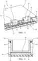
Figure 1 is a schematic perspective view of the electronic unit without the thermally conductive insert elements according to one embodiment of the invention. -
Figure 2 is a schematic perspective view of the electronic unit offigure 1 arranged with the thermally conductive insert elements not according to the invention. -
Figure 3 is an axial cut view according to plan 3-3 offigure 2 . -
Figure 4 is zoom view of the circledarea 4 offigure 3 . -
Figure 5 is a schematic perspective view of the electronic unit with thermally conductive insert elements not according to an embodiment of the invention. -
Figure 6 is an axial cut view of one thermally conductive insert element according to plan 6-6 offigure 5 . -
Figure 7 is an embodiment according to the claimed invention -
Figure 8 is a schematic perspective view of the electronic unit arranged with a cold plate comprising thermally conductive insert elements according to another embodiment of the invention. -
Figure 9 is a top perspective view of the cold plate offigure 8 . -
Figure 10 is a bottom perspective view of the cold plate offigure 8 . - According to
figure 1 , anelectronic unit 10 is shown. Theelectronic unit 10 may be an electronic control unit for car or any kind ofelectronic unit 10, saidelectronic unit 10 comprises ahousing 12. Thehousing 12 comprises abottom wall 14 on which a printedcircuit board 16 is arranged and a top wall or atop cover 18 that comprises afirst opening 20 and a second opening 22 or a first cut-out and a second cut-out. The first opening 20 and thesecond opening 22 are opened square shape and are respectively arranged above a firstheating source element 24 and a secondheating source element 26, bothheating source elements circuit board 16. - An
heating source element - According to
figure 2 andfigure 3 theelectronic unit 10 comprises a first thermallyconductive insert element 28, or thermally conductive pedestal, and a second thermallyconductive insert element 30, both thermally conductive insert element being distinct from thehousing 12. The first thermallyconductive insert element 28 and the second thermallyconductive element 30 cooperate mechanically respectively with thefirst opening 20 and the second opening 22 of thetop cover 18, and respectively with the firstheating source element 24 and the secondheating source element 26 such that heating dissipation of the firstheating source element 24 and the heating dissipation of the secondheating source element 26 are allowed. - As each thermally
conductive insert element housing 12, they may have thermal conductivity different than thehousing 12. Generally, the present description provides the advantage of usingstandard housing 12 material such as plastic or aluminum while the thermallyconductive insert elements housing 12. Both thermallyconductive insert elements conductive insert elements heating source element conductive insert element 28 relative to saidheating source element 24 may be made of silver. - According to the embodiment shown in
figure 2 andfigure 3 , each thermallyconductive insert element blind cavity opening bottom wall extremity heating source element - According to
figure 4 , one embodiment of the arrangement of the second thermallyconductive insert element 30 is shown. Arrangement of the first thermallyconductive insert element 28 may be similar. - The top layer of the
printed circuit board 16 comprises one electronic component as the secondheating source element 26. Said electronic component may be as a non-limiting examples, a microcontroller or a solid state power switch. Thebottom wall extremity 38 of the second thermallyconductive insert element 30 is in thermal contact with the secondheating source element 26. More particularly, the secondheating source element 26 is in thermal contact with the second thermallyconductive insert element 30 by means of athermal interface material 40 as thermal paste arranged on the top surface of the secondheating source element 26. Alternatively, thebottom wall extremity 38 of the second thermallyconductive insert element 30 may be in direct thermal contact with the top surface of the secondheating source element 26, i.e. without thermal interface material such that heat transfer is less optimized. - The opened top extremity of the second thermally
conductive insert element 30 is arranged inside the second opening 22 and comprisesfixing means 42 cooperating with the around inside of the second opening 22 of thetop cover 18 such that watertight is guaranteed between the second thermallyconductive insert element 30 and thetop cover 18. In other words, globally, the fixing means 42 are configured to entirely fix the top extremity of a thermallyconductive insert element top cover 18 around an opening 20, 22 of thetop cover 18. - Generally, the fixing means 42 comprise an adhesive paste joint that suits with most of the
housing 12 materials that have to be fixed with the thermallyconductive insert element - In case of the
top cover 18 is made of metallic material, and the first thermallyconductive insert element 28 and the second thermallyconductive insert element 30 are also made of metallic material, said first and second thermallyconductive insert elements top cover 18 such that a brazed join is formed between each thermallyconductive insert element top cover 18 providing watertight effect. As alternatives, the opened top extremity of the thermally conductive insert may be brazed with the around of the opening on top of thetop cover 18 or on the bottom side of thetop cover 18. - According to
figure 5 , thetop cover 18 of theelectronic unit 10 comprises a variant of the first thermallyconductive insert element 28 and the second thermallyconductive insert element 30. Thetop cover 18 is equipped with a third thermallyconductive insert element 44 and a fourth thermallyconductive insert element 46 that differ from the first thermallyconductive insert element 28 and the second thermallyconductive insert element 30 by comprising aflange flange conductive insert element conductive insert element 44 and of the fourth thermallyconductive insert element 46 with thetop cover 18. Additionally, in case of a metallictop cover 18, saidflanges conductive insert element 44 and from the fourth thermallyconductive insert element 46 to the metallictop cover 18. - According to
figure 5 and figure 6 , theflange 50 is fixed around thesecond opening 22 of thetop cover 18, on the top surface, or external surface, of thetop cover 18. Alternatively, theflange 50 may be fixed on the bottom surface, or internal surface, of thetop cover 18. Theflange 50 may be glued to thetop cover 18 by the usage of adhesive paste joint. In case of metallictop cover 18, theflange 50 may be brazed with thetop cover 18 such that a brazed joint is formed between theflange 50 and thetop cover 18. - According to
figure 7 , thetop cover 18 is arranged with the fourth thermallyconductive insert element 46. Theflange 50 is mounted around thesecond opening 22, on the top surface of thetop cover 18. More particularly, thetop cover 18 comprises athickness reduction area 52 all around tofirst opening 20. The thickness reduction is equal or greater than the thickness of theflange 50 such that theflange 50 does not protrude on the top surface of thetop cover 18. While the thickness reduction is equal to the corresponding thickness of theflange 50, the surface area of thetop cover 18 comprising theflange 50 is a flat surface. - The embodiment shown in
figure 7 differs from the embodiment offigure 5 and figure 6 such that the top surface of thetop cover 18 wherein theflange 50 is mounted, i.e. thethickness reduction area 52 of thetop cover 18 comprising theflange 50, is a flat surface. In that case, theflange 50 of the fourth thermallyconductive insert element 46 does not affect the top surface plan of thetop cover 18. - According to
figure 8 , theelectronic unit 10 comprises acold plate 54. Thecold plate 54 is arranged on the top surface of thehousing 12. According tofigure 9 and figure 10 , the mechanical cooperation between thecold plate 54 and the thermallyconductive insert elements top cover 18 and the third thermallyconductive insert element 44 and the fourth the thermallyconductive insert element 46 shown atfigure 5, figure 6 andfigure 7 . In other words, thecold plate 54 comprises twoother openings conductive insert elements figures 5, 6 and7 . - Alternatively, the thermally conductive insert elements arranged with the
cold plate 54 may be similar that the first thermallyconductive insert element 28 and the second thermallyconductive insert element 30 as shown atfigure 2 ,figure 3 and figure 4 . - According to
figure 8 ,figure 9 and figure 10 , as being fixed to thecold plate 54, when assembled with theelectronic unit 10housing 12, each thermallyconductive insert element cold plate 54 is arranged through anopening housing 12 of theelectronic unit 10, i.e. anopening top cover 18 as defined atfigure 1 . From that embodiment the thermallyconductive insert elements housing 12, but they are primarily fixed with thecold plate 54. In order to guaranteed watertight between thecold plate 54 and theopening housing 12, adhesive paste joint may be added between thecold plate 54 and the top wall of thehousing 12. - According to
figure 8 ,figure 9 and figure 10 , thecold plate 54 is more particularly a liquidcoolant cold plate 54 comprising acoolant liquid inlet 60 and acoolant liquid outlet 62. - More particularly, in order to efficiently cool down the thermally
conductive insert elements cold plate 54 comprises liquid coolant wall guides 64, 66, 68, as liquid coolant deflector, configured to convey the liquid coolant from thecoolant liquid inlet 60 to each thermallyconductive insert element conductive insert element coolant liquid outlet 62. - Alternatively, each thermally
conductive insert element - The invention is not limited to the shape of the
openings conductive insert elements figure 7 . Other shape may be also suitable for the invention. In addition, other thermal conductive material than the ones cited in that present description may also be suitable for the thermallyconductive insert elements conductive insert elements heating source element
Claims (13)
- Electronic unit (10) comprisinga housing (12) comprising at least a first opening (20) and a top cover (18);a printed circuit board (16) mounted inside the housing (12) and comprising at least a first heating source element (24) on the top layer of the printed circuit board (16);at least a first thermally conductive insert element (28) distinct from the housing (12);the top cover (18) comprises the first opening (20);the first thermally conductive insert element (28) extends from its top extremity arranged around the first opening (20) to its bottom extremity in thermal contact with the first heating source element (24) such that heating dissipation of the first heating source element (24) is allowed;fixing means (42) are configured to entirely fix the top extremity of the first thermally conductive insert element (28) with the top cover (18) around the first opening (20); and characterised in thatthe top extremity of the first thermally conductive insert element (28) comprises a flange (50) arranged around the top extremity and fixed with the top cover (18) around the first opening (20), the top cover (18) comprising a thickness reduction area (52) all around the first opening (20), said reduction in thickness being equal to or greater than the thickness of the flange (50) so that the flange (50) does not protrude from the top surface of the top cover (18).
- Electronic unit (10) according to the preceding claim characterized in that the first thermal conductive insert element (28) comprising a blind cavity (32) extending from its opened top extremity entirely fixed around the first opening (20) to its bottom wall extremity (36) in thermal contact with the first heating source element (24).
- Electronic unit (10) according to any one of the preceding claims characterized in that the first thermally conductive insert element (28) has a thermal conductivity greater than the top cover (18).
- Electronic unit (10) according to any one of the preceding claims characterized in that the fixing means (42) are watertight fixing means (42) around the first opening (20).
- Electronic unit (10) according to any one of the preceding claims wherein the top cover (18) is made of a liquid coolant cold plate (54), the top cover (18) comprising a coolant liquid inlet (60), a coolant liquid outlet (62), and liquid coolant wall guides (64, 66, 68) configured to convey the liquid coolant from the coolant liquid inlet (60) to the first thermally conductive insert element (28) and from the first thermally conductive insert element (28) to the coolant liquid outlet (62).
- Electronic unit (10) according to any one of the preceding claims characterized in that the housing (12) comprises a top wall having at least one another opening; the top cover (18) being arranged onto the top wall; the first thermally conductive insert element (28) being arranged through the another opening.
- Electronic unit (10) according to claim 6 characterized in that the top wall is made of plastic material.
- Electronic unit (10) according to any one of the preceding claims characterized in that the first thermally conductive insert element (28) and the top cover (18) are made of metallic material.
- Electronic unit (10) according to claim 8 characterized in that the first thermally conductive insert element (28) is made of cooper alloy material; and the top cover (18) is made of aluminum alloy material.
- Electronic unit (10) according to any one of the preceding claims characterized in that the fixing means (42) comprise an adhesive paste joint.
- Electronic unit (10) according to any one of the claims 8 and 9 characterized in that the fixing means (42) comprises a brazed joint.
- Electronic unit (10) according to any one of the preceding claims characterized in thatthe printed circuit board (16) comprises a second heating source element (26) on the top layer of the printed circuit board (16);the top cover (18) comprises a second opening (22);the electronic unit (10) comprises a second thermally conductive insert element (30) distinct from the housing (12) and extending from its top extremity arranged around the second opening (22), to its bottom extremity (38) in thermal contact with the second heating source element (26) such that heating dissipation of the second heating source element (26) is allowed; said second thermally conductive insert element (30) comprising a thermal conductivity different to the first thermally conductive insert element (28).
- Electronic unit (10) according to claim 12 characterized in that the second thermally conductive insert element (30) is made of silver material.
Priority Applications (3)
| Application Number | Priority Date | Filing Date | Title |
|---|---|---|---|
| EP19152913.0A EP3684154B1 (en) | 2019-01-21 | 2019-01-21 | Thermally conductive insert element for electronic unit |
| US16/747,097 US11076503B2 (en) | 2019-01-21 | 2020-01-20 | Thermally conductive insert element for electronic unit |
| CN202010069014.4A CN111465258B (en) | 2019-01-21 | 2020-01-21 | Thermally conductive insert for an electronic unit |
Applications Claiming Priority (1)
| Application Number | Priority Date | Filing Date | Title |
|---|---|---|---|
| EP19152913.0A EP3684154B1 (en) | 2019-01-21 | 2019-01-21 | Thermally conductive insert element for electronic unit |
Publications (2)
| Publication Number | Publication Date |
|---|---|
| EP3684154A1 EP3684154A1 (en) | 2020-07-22 |
| EP3684154B1 true EP3684154B1 (en) | 2024-03-06 |
Family
ID=65138943
Family Applications (1)
| Application Number | Title | Priority Date | Filing Date |
|---|---|---|---|
| EP19152913.0A Active EP3684154B1 (en) | 2019-01-21 | 2019-01-21 | Thermally conductive insert element for electronic unit |
Country Status (3)
| Country | Link |
|---|---|
| US (1) | US11076503B2 (en) |
| EP (1) | EP3684154B1 (en) |
| CN (1) | CN111465258B (en) |
Families Citing this family (1)
| Publication number | Priority date | Publication date | Assignee | Title |
|---|---|---|---|---|
| EP3923689B1 (en) * | 2020-06-12 | 2024-04-24 | Aptiv Technologies AG | Cooling device and its manufacturing method |
Citations (1)
| Publication number | Priority date | Publication date | Assignee | Title |
|---|---|---|---|---|
| US20130329367A1 (en) * | 2012-06-07 | 2013-12-12 | Askey Computer Corp. | Electronic device having heat-dissipating structure |
Family Cites Families (21)
| Publication number | Priority date | Publication date | Assignee | Title |
|---|---|---|---|---|
| US2780757A (en) * | 1955-08-02 | 1957-02-05 | Texas Instruments Inc | Rectifier structure |
| US4138692A (en) * | 1977-09-12 | 1979-02-06 | International Business Machines Corporation | Gas encapsulated cooling module |
| JP3877098B2 (en) * | 1997-11-25 | 2007-02-07 | 株式会社デンソー | Liquid cooling circuit device |
| JP2002046482A (en) * | 2000-07-31 | 2002-02-12 | Honda Motor Co Ltd | Heat sink type cooling device |
| US6881077B2 (en) * | 2002-07-22 | 2005-04-19 | Siemens Vdo Automotive Corporation | Automotive control module housing |
| TW556475B (en) * | 2003-02-19 | 2003-10-01 | Accton Technology Corp | A cover apparatus for dissipating heat and shielding electromagnetic interference |
| US7180745B2 (en) * | 2003-10-10 | 2007-02-20 | Delphi Technologies, Inc. | Flip chip heat sink package and method |
| JP2006190707A (en) * | 2004-12-28 | 2006-07-20 | Toshiba Corp | Electronic apparatus and television receiver applied with this electronic apparatus |
| JP4785878B2 (en) * | 2008-02-06 | 2011-10-05 | 本田技研工業株式会社 | Cooling device and electric vehicle equipped with the cooling device |
| JP4819071B2 (en) * | 2008-02-06 | 2011-11-16 | 本田技研工業株式会社 | Electric vehicle and cooling method for DC / DC converter for vehicle |
| JP5402200B2 (en) * | 2009-04-20 | 2014-01-29 | 株式会社リコー | Heat transfer mechanism and information equipment |
| KR101289313B1 (en) * | 2009-05-22 | 2013-07-24 | 엘에스산전 주식회사 | Water-cooling type cooler and inverter having the same |
| JP2011054640A (en) * | 2009-08-31 | 2011-03-17 | Funai Electric Co Ltd | Shield package substrate |
| JP5687717B2 (en) * | 2010-02-25 | 2015-03-18 | トムソン ライセンシングThomson Licensing | Small multilayer radiant cooling case with hidden quick release snap |
| JP5981463B2 (en) * | 2011-03-09 | 2016-08-31 | トムソン ライセンシングThomson Licensing | Electronic equipment |
| KR20140041701A (en) * | 2011-07-14 | 2014-04-04 | 톰슨 라이센싱 | Set top box having snap-in heat sink and smart card reader with a hold down for retaining the heat sink |
| KR101608182B1 (en) * | 2012-08-02 | 2016-03-31 | 미쓰비시덴키 가부시키가이샤 | Heat dissipation plate |
| JP2014093414A (en) * | 2012-11-02 | 2014-05-19 | Hitachi Automotive Systems Ltd | Electronic control device |
| US20170038154A1 (en) * | 2015-08-06 | 2017-02-09 | Chaun-Choung Technology Corp. | Vapor chamber structure having stretchable heated part |
| JP6540496B2 (en) * | 2015-12-17 | 2019-07-10 | 株式会社デンソー | Power converter |
| DE102016106180A1 (en) * | 2016-04-05 | 2017-10-05 | Dr. Ing. H.C. F. Porsche Aktiengesellschaft | Cooling device for cooling at least one electrical component of a vehicle |
-
2019
- 2019-01-21 EP EP19152913.0A patent/EP3684154B1/en active Active
-
2020
- 2020-01-20 US US16/747,097 patent/US11076503B2/en active Active
- 2020-01-21 CN CN202010069014.4A patent/CN111465258B/en active Active
Patent Citations (1)
| Publication number | Priority date | Publication date | Assignee | Title |
|---|---|---|---|---|
| US20130329367A1 (en) * | 2012-06-07 | 2013-12-12 | Askey Computer Corp. | Electronic device having heat-dissipating structure |
Also Published As
| Publication number | Publication date |
|---|---|
| US20200236811A1 (en) | 2020-07-23 |
| CN111465258A (en) | 2020-07-28 |
| CN111465258B (en) | 2022-10-14 |
| EP3684154A1 (en) | 2020-07-22 |
| US11076503B2 (en) | 2021-07-27 |
Similar Documents
| Publication | Publication Date | Title |
|---|---|---|
| US6661664B2 (en) | Electronic module with high cooling power | |
| US7742307B2 (en) | High performance power device | |
| JP4404726B2 (en) | Automotive power converter | |
| US6408934B1 (en) | Cooling module | |
| JP4859823B2 (en) | COOLING DEVICE AND ELECTRONIC DEVICE USING THE SAME | |
| EP2738803A2 (en) | Phase change heat sink for transient thermal management | |
| US20070217148A1 (en) | Power supply cooling | |
| JP5783212B2 (en) | Power supply | |
| JP2006271063A (en) | Cooling structure of bus bar | |
| EP3684154B1 (en) | Thermally conductive insert element for electronic unit | |
| JPS5893264A (en) | Cooler for device | |
| CN207219146U (en) | Heat abstractor for heat dissipation for circuit board | |
| WO2019130442A1 (en) | Motor drive device | |
| WO2016147345A1 (en) | Power supply module and air conditioner outdoor unit using same | |
| EP3843512A1 (en) | Cooling system for cooling an electronic component, method for assembling a cooling system, electronic control unit and vehicle | |
| EP2816591B1 (en) | Electrical component cooling device and heat source equipment for a refrigeration cycle apparatus provided with same | |
| CN211210276U (en) | Heat radiation structure | |
| WO2017115627A1 (en) | Inverter | |
| JP2007067067A (en) | Resin injection type power circuit unit | |
| KR101360730B1 (en) | Cooling device and electronic device thereof | |
| JP6794757B2 (en) | Electronic circuit equipment | |
| JP2006173243A (en) | Printed wiring board and heat dissipation structure of printed circuit board | |
| CN212277180U (en) | Solid state source and cooking device | |
| JP6918225B2 (en) | Power converter | |
| CN219576843U (en) | Power supply device |
Legal Events
| Date | Code | Title | Description |
|---|---|---|---|
| PUAI | Public reference made under article 153(3) epc to a published international application that has entered the european phase |
Free format text: ORIGINAL CODE: 0009012 |
|
| STAA | Information on the status of an ep patent application or granted ep patent |
Free format text: STATUS: THE APPLICATION HAS BEEN PUBLISHED |
|
| AK | Designated contracting states |
Kind code of ref document: A1 Designated state(s): AL AT BE BG CH CY CZ DE DK EE ES FI FR GB GR HR HU IE IS IT LI LT LU LV MC MK MT NL NO PL PT RO RS SE SI SK SM TR |
|
| AX | Request for extension of the european patent |
Extension state: BA ME |
|
| STAA | Information on the status of an ep patent application or granted ep patent |
Free format text: STATUS: REQUEST FOR EXAMINATION WAS MADE |
|
| 17P | Request for examination filed |
Effective date: 20210114 |
|
| RBV | Designated contracting states (corrected) |
Designated state(s): AL AT BE BG CH CY CZ DE DK EE ES FI FR GB GR HR HU IE IS IT LI LT LU LV MC MK MT NL NO PL PT RO RS SE SI SK SM TR |
|
| STAA | Information on the status of an ep patent application or granted ep patent |
Free format text: STATUS: EXAMINATION IS IN PROGRESS |
|
| 17Q | First examination report despatched |
Effective date: 20220401 |
|
| RAP3 | Party data changed (applicant data changed or rights of an application transferred) |
Owner name: APTIV TECHNOLOGIES LIMITED |
|
| GRAP | Despatch of communication of intention to grant a patent |
Free format text: ORIGINAL CODE: EPIDOSNIGR1 |
|
| STAA | Information on the status of an ep patent application or granted ep patent |
Free format text: STATUS: GRANT OF PATENT IS INTENDED |
|
| INTG | Intention to grant announced |
Effective date: 20231108 |
|
| GRAS | Grant fee paid |
Free format text: ORIGINAL CODE: EPIDOSNIGR3 |
|
| P01 | Opt-out of the competence of the unified patent court (upc) registered |
Effective date: 20231110 |
|
| GRAA | (expected) grant |
Free format text: ORIGINAL CODE: 0009210 |
|
| STAA | Information on the status of an ep patent application or granted ep patent |
Free format text: STATUS: THE PATENT HAS BEEN GRANTED |
|
| AK | Designated contracting states |
Kind code of ref document: B1 Designated state(s): AL AT BE BG CH CY CZ DE DK EE ES FI FR GB GR HR HU IE IS IT LI LT LU LV MC MK MT NL NO PL PT RO RS SE SI SK SM TR |
|
| REG | Reference to a national code |
Ref country code: GB Ref legal event code: FG4D |
|
| REG | Reference to a national code |
Ref country code: CH Ref legal event code: EP |
|
| REG | Reference to a national code |
Ref country code: IE Ref legal event code: FG4D |
|
| REG | Reference to a national code |
Ref country code: DE Ref legal event code: R096 Ref document number: 602019047611 Country of ref document: DE |