JP4819071B2 - Electric vehicle and cooling method for DC / DC converter for vehicle - Google Patents
Electric vehicle and cooling method for DC / DC converter for vehicle Download PDFInfo
- Publication number
- JP4819071B2 JP4819071B2 JP2008026445A JP2008026445A JP4819071B2 JP 4819071 B2 JP4819071 B2 JP 4819071B2 JP 2008026445 A JP2008026445 A JP 2008026445A JP 2008026445 A JP2008026445 A JP 2008026445A JP 4819071 B2 JP4819071 B2 JP 4819071B2
- Authority
- JP
- Japan
- Prior art keywords
- converter
- cooling
- arm element
- coolant
- storage device
- Prior art date
- Legal status (The legal status is an assumption and is not a legal conclusion. Google has not performed a legal analysis and makes no representation as to the accuracy of the status listed.)
- Expired - Fee Related
Links
Images


Classifications
-
- H—ELECTRICITY
- H01—ELECTRIC ELEMENTS
- H01L—SEMICONDUCTOR DEVICES NOT COVERED BY CLASS H10
- H01L23/00—Details of semiconductor or other solid state devices
- H01L23/34—Arrangements for cooling, heating, ventilating or temperature compensation ; Temperature sensing arrangements
- H01L23/46—Arrangements for cooling, heating, ventilating or temperature compensation ; Temperature sensing arrangements involving the transfer of heat by flowing fluids
- H01L23/473—Arrangements for cooling, heating, ventilating or temperature compensation ; Temperature sensing arrangements involving the transfer of heat by flowing fluids by flowing liquids
-
- F—MECHANICAL ENGINEERING; LIGHTING; HEATING; WEAPONS; BLASTING
- F28—HEAT EXCHANGE IN GENERAL
- F28F—DETAILS OF HEAT-EXCHANGE AND HEAT-TRANSFER APPARATUS, OF GENERAL APPLICATION
- F28F3/00—Plate-like or laminated elements; Assemblies of plate-like or laminated elements
- F28F3/12—Elements constructed in the shape of a hollow panel, e.g. with channels
-
- H—ELECTRICITY
- H02—GENERATION; CONVERSION OR DISTRIBUTION OF ELECTRIC POWER
- H02M—APPARATUS FOR CONVERSION BETWEEN AC AND AC, BETWEEN AC AND DC, OR BETWEEN DC AND DC, AND FOR USE WITH MAINS OR SIMILAR POWER SUPPLY SYSTEMS; CONVERSION OF DC OR AC INPUT POWER INTO SURGE OUTPUT POWER; CONTROL OR REGULATION THEREOF
- H02M7/00—Conversion of ac power input into dc power output; Conversion of dc power input into ac power output
- H02M7/003—Constructional details, e.g. physical layout, assembly, wiring or busbar connections
-
- H—ELECTRICITY
- H05—ELECTRIC TECHNIQUES NOT OTHERWISE PROVIDED FOR
- H05K—PRINTED CIRCUITS; CASINGS OR CONSTRUCTIONAL DETAILS OF ELECTRIC APPARATUS; MANUFACTURE OF ASSEMBLAGES OF ELECTRICAL COMPONENTS
- H05K7/00—Constructional details common to different types of electric apparatus
- H05K7/20—Modifications to facilitate cooling, ventilating, or heating
- H05K7/2089—Modifications to facilitate cooling, ventilating, or heating for power electronics, e.g. for inverters for controlling motor
- H05K7/20927—Liquid coolant without phase change
-
- B—PERFORMING OPERATIONS; TRANSPORTING
- B60—VEHICLES IN GENERAL
- B60K—ARRANGEMENT OR MOUNTING OF PROPULSION UNITS OR OF TRANSMISSIONS IN VEHICLES; ARRANGEMENT OR MOUNTING OF PLURAL DIVERSE PRIME-MOVERS IN VEHICLES; AUXILIARY DRIVES FOR VEHICLES; INSTRUMENTATION OR DASHBOARDS FOR VEHICLES; ARRANGEMENTS IN CONNECTION WITH COOLING, AIR INTAKE, GAS EXHAUST OR FUEL SUPPLY OF PROPULSION UNITS IN VEHICLES
- B60K1/00—Arrangement or mounting of electrical propulsion units
- B60K2001/003—Arrangement or mounting of electrical propulsion units with means for cooling the electrical propulsion units
- B60K2001/005—Arrangement or mounting of electrical propulsion units with means for cooling the electrical propulsion units the electric storage means
-
- B—PERFORMING OPERATIONS; TRANSPORTING
- B60—VEHICLES IN GENERAL
- B60L—PROPULSION OF ELECTRICALLY-PROPELLED VEHICLES; SUPPLYING ELECTRIC POWER FOR AUXILIARY EQUIPMENT OF ELECTRICALLY-PROPELLED VEHICLES; ELECTRODYNAMIC BRAKE SYSTEMS FOR VEHICLES IN GENERAL; MAGNETIC SUSPENSION OR LEVITATION FOR VEHICLES; MONITORING OPERATING VARIABLES OF ELECTRICALLY-PROPELLED VEHICLES; ELECTRIC SAFETY DEVICES FOR ELECTRICALLY-PROPELLED VEHICLES
- B60L2240/00—Control parameters of input or output; Target parameters
- B60L2240/40—Drive Train control parameters
- B60L2240/52—Drive Train control parameters related to converters
- B60L2240/525—Temperature of converter or components thereof
-
- B—PERFORMING OPERATIONS; TRANSPORTING
- B60—VEHICLES IN GENERAL
- B60W—CONJOINT CONTROL OF VEHICLE SUB-UNITS OF DIFFERENT TYPE OR DIFFERENT FUNCTION; CONTROL SYSTEMS SPECIALLY ADAPTED FOR HYBRID VEHICLES; ROAD VEHICLE DRIVE CONTROL SYSTEMS FOR PURPOSES NOT RELATED TO THE CONTROL OF A PARTICULAR SUB-UNIT
- B60W10/00—Conjoint control of vehicle sub-units of different type or different function
- B60W10/24—Conjoint control of vehicle sub-units of different type or different function including control of energy storage means
- B60W10/26—Conjoint control of vehicle sub-units of different type or different function including control of energy storage means for electrical energy, e.g. batteries or capacitors
-
- B—PERFORMING OPERATIONS; TRANSPORTING
- B60—VEHICLES IN GENERAL
- B60W—CONJOINT CONTROL OF VEHICLE SUB-UNITS OF DIFFERENT TYPE OR DIFFERENT FUNCTION; CONTROL SYSTEMS SPECIALLY ADAPTED FOR HYBRID VEHICLES; ROAD VEHICLE DRIVE CONTROL SYSTEMS FOR PURPOSES NOT RELATED TO THE CONTROL OF A PARTICULAR SUB-UNIT
- B60W10/00—Conjoint control of vehicle sub-units of different type or different function
- B60W10/28—Conjoint control of vehicle sub-units of different type or different function including control of fuel cells
-
- H—ELECTRICITY
- H01—ELECTRIC ELEMENTS
- H01L—SEMICONDUCTOR DEVICES NOT COVERED BY CLASS H10
- H01L2924/00—Indexing scheme for arrangements or methods for connecting or disconnecting semiconductor or solid-state bodies as covered by H01L24/00
- H01L2924/0001—Technical content checked by a classifier
- H01L2924/0002—Not covered by any one of groups H01L24/00, H01L24/00 and H01L2224/00
-
- H—ELECTRICITY
- H01—ELECTRIC ELEMENTS
- H01M—PROCESSES OR MEANS, e.g. BATTERIES, FOR THE DIRECT CONVERSION OF CHEMICAL ENERGY INTO ELECTRICAL ENERGY
- H01M2250/00—Fuel cells for particular applications; Specific features of fuel cell system
- H01M2250/20—Fuel cells in motive systems, e.g. vehicle, ship, plane
-
- Y—GENERAL TAGGING OF NEW TECHNOLOGICAL DEVELOPMENTS; GENERAL TAGGING OF CROSS-SECTIONAL TECHNOLOGIES SPANNING OVER SEVERAL SECTIONS OF THE IPC; TECHNICAL SUBJECTS COVERED BY FORMER USPC CROSS-REFERENCE ART COLLECTIONS [XRACs] AND DIGESTS
- Y02—TECHNOLOGIES OR APPLICATIONS FOR MITIGATION OR ADAPTATION AGAINST CLIMATE CHANGE
- Y02E—REDUCTION OF GREENHOUSE GAS [GHG] EMISSIONS, RELATED TO ENERGY GENERATION, TRANSMISSION OR DISTRIBUTION
- Y02E60/00—Enabling technologies; Technologies with a potential or indirect contribution to GHG emissions mitigation
- Y02E60/30—Hydrogen technology
- Y02E60/50—Fuel cells
-
- Y—GENERAL TAGGING OF NEW TECHNOLOGICAL DEVELOPMENTS; GENERAL TAGGING OF CROSS-SECTIONAL TECHNOLOGIES SPANNING OVER SEVERAL SECTIONS OF THE IPC; TECHNICAL SUBJECTS COVERED BY FORMER USPC CROSS-REFERENCE ART COLLECTIONS [XRACs] AND DIGESTS
- Y02—TECHNOLOGIES OR APPLICATIONS FOR MITIGATION OR ADAPTATION AGAINST CLIMATE CHANGE
- Y02T—CLIMATE CHANGE MITIGATION TECHNOLOGIES RELATED TO TRANSPORTATION
- Y02T90/00—Enabling technologies or technologies with a potential or indirect contribution to GHG emissions mitigation
- Y02T90/40—Application of hydrogen technology to transportation, e.g. using fuel cells
Description
本発明は、スイッチング素子等の発熱体を冷却するための冷却装置を備える電気車両及び車両用DC/DCコンバータの冷却方法に関する。 The present invention relates to an electric vehicle including a cooling device for cooling a heating element such as a switching element, and a cooling method for a DC / DC converter for a vehicle.
従来から、MOSFETあるいはIGBT等のスイッチング素子を用いたスイッチング電源であるDC/DCコンバータ装置が広汎に利用されている。 Conventionally, DC / DC converter devices, which are switching power supplies using switching elements such as MOSFETs or IGBTs, have been widely used.
例えば、走行駆動源としてモータを用いる車両(電気車両)の一形態として、蓄電装置とインバータ駆動モータとの間に直流電圧を昇降圧するDC/DCコンバータ装置が介装された車両(ここでは、電気自動車という。)が提案されている。この電気自動車では、モータの駆動時に、DC/DCコンバータ装置により蓄電装置の電圧を昇圧してインバータに印加し、モータの回生時には、インバータに発生する回生電圧をDC/DCコンバータ装置により降圧して蓄電装置側に印加して充電等する。 For example, as one form of a vehicle (electric vehicle) that uses a motor as a travel drive source, a vehicle (here, an electric vehicle) in which a DC / DC converter device that steps up and down a DC voltage is interposed between a power storage device and an inverter drive motor. Automobiles) have been proposed. In this electric vehicle, when the motor is driven, the voltage of the power storage device is boosted by the DC / DC converter device and applied to the inverter, and during regeneration of the motor, the regenerative voltage generated in the inverter is stepped down by the DC / DC converter device. The battery is charged by being applied to the power storage device side.
また、電気車両の他の形態として、燃料電池とインバータ駆動モータとを直接接続し、この接続点と蓄電装置との間に直流電圧を昇降圧するDC/DCコンバータ装置が介装され、燃料電池を主電源装置とし、蓄電装置を前記主電源装置をアシストする従電源装置とした車両(ここでは、燃料電池車両という。)も提案されている。 As another form of the electric vehicle, a fuel cell and an inverter drive motor are directly connected, and a DC / DC converter device for stepping up / down a DC voltage is interposed between the connection point and the power storage device. There has also been proposed a vehicle (herein referred to as a fuel cell vehicle) in which a main power supply device is used and a power storage device is a sub power supply device that assists the main power supply device.
この燃料電池車両では、モータの駆動時に、燃料電池の電圧とDC/DCコンバータ装置により昇圧した蓄電装置の電圧とを併合してインバータに印加し、モータの回生時には、インバータに発生する回生電圧をDC/DCコンバータ装置により降圧して蓄電装置側に印加して充電等する。また、燃料電池の発生電力に余剰分があるとき、降圧して蓄電装置側に印加して充電等する。 In this fuel cell vehicle, when the motor is driven, the voltage of the fuel cell and the voltage of the power storage device boosted by the DC / DC converter device are combined and applied to the inverter, and when the motor is regenerated, the regenerative voltage generated in the inverter is applied. The voltage is stepped down by the DC / DC converter device, applied to the power storage device side, and charged. Further, when there is a surplus in the generated power of the fuel cell, it is stepped down, applied to the power storage device side, and charged.
ところで、このようなDC/DCコンバータ装置を構成する半導体モジュール(スイッチングモジュール)、すなわち、前記スイッチング素子やダイオード、特にスイッチング素子は、その駆動時に相当な発熱を伴うため十分な冷却が必要である。そこで、一般に、水冷からなる冷却液流路を備えた冷却装置が用いられているが、当該冷却装置は車載等を考慮すると、十分な冷却能力と小型化の両立が重要である。 By the way, a semiconductor module (switching module) constituting such a DC / DC converter device, that is, the switching element and the diode, particularly the switching element, requires considerable cooling because it generates a considerable amount of heat when driven. Therefore, in general, a cooling device having a cooling liquid flow path composed of water cooling is used. However, considering the in-vehicle etc., it is important to satisfy both sufficient cooling capacity and downsizing.
例えば、特許文献1には、シリーズハイブリット車においてパワー半導体素子を冷却するパワーモジュールの冷却装置の冷却能力を向上させると共に、パワーモジュール全体の大きさを小型化するために、発電機側のインバータの還流ダイオードとモータ側インバータのスイッチング素子とを各相ごとに冷却板上に一直線上に配列し、冷却材配管を各相ごとの前記直線に沿って配置させることが記載されている。すなわち、駆動時に発熱が大きい部分に沿って冷却材配管を設けると共に、発電時に使用される部分については冷却をせず、流路の曲がり回数の低減等により、冷却系の小型化を図ることができるとされている。
For example, in
ところで、例えば、燃料電池を搭載する燃料電池車両では、その高出力時に端子間電圧が下がってしまう特性があるため、車両として回生と駆動では同じ出力を行ったとしても、DC/DCコンバータを構成するスイッチング素子であるアーム素子の1次側1Sと2次側2Sの電圧差は、駆動時に比べてモータ逆起電圧の影響を受ける回生時(発電時)の方が大きくなり、つまり、回生側の方が熱的な条件が厳しいことになる。
By the way, for example, in a fuel cell vehicle equipped with a fuel cell, there is a characteristic that the voltage between terminals decreases at the time of high output. Therefore, even if the same output is performed for regeneration and driving as a vehicle, a DC / DC converter is configured. The voltage difference between the
従って、上記特許文献1に記載の装置を用いた場合には、DC/DCコンバータを構成する回生側のスイッチング素子の冷却が不十分となり、十分な回生量を得ることが困難であり、車両の回生可能電力量の低下を惹起することになる。
Therefore, when the apparatus described in
本発明は、上記従来の課題を考慮してなされたものであり、DC/DCコンバータの冷却装置を備える電気車両において、回生時におけるスイッチング素子の冷却性能を向上させることができ、車両の回生可能電力量を増加させることができる電気車両及び車両用DC/DCコンバータの冷却方法を提供することを目的とする。 The present invention has been made in consideration of the above-described conventional problems, and in an electric vehicle including a DC / DC converter cooling device, the cooling performance of the switching element during regeneration can be improved, and the vehicle can be regenerated. It is an object of the present invention to provide a cooling method for an electric vehicle and a DC / DC converter for a vehicle that can increase the amount of electric power.
本発明に係る電気車両は、車輪を回転させる電動機と、前記電動機に電力を並列的に供給する発電装置及び蓄電装置と、前記蓄電装置と前記発電装置との間に接続され前記蓄電装置に発生する電圧を変換して前記電動機側に印加すると共に前記電動機の回生動作による回生電圧又は前記発電装置の発電電圧を変換して前記蓄電装置側に印加するDC/DCコンバータと、冷却液が流通されると共に、一部に折り返し部が形成された冷却液流路を有し、前記DC/DCコンバータを冷却する冷却装置とを備え、前記DC/DCコンバータは、前記蓄電装置と前記電動機側との間に、少なくとも1組の上アーム素子と下アーム素子からなる相アーム素子を有し、前記冷却装置は、前記折り返し部の上流側の前記冷却液で前記上アーム素子を冷却すると共に、前記折り返し部の下流側の前記冷却液で前記下アーム素子を冷却するように形成されていることを特徴とする。前記発電装置は燃料電池としてもよい。 An electric vehicle according to the present invention includes an electric motor that rotates a wheel, a power generation device and a power storage device that supply power to the motor in parallel, and is generated between the power storage device and the power generation device. A DC / DC converter that converts the voltage to be applied and applies it to the motor side, converts the regenerative voltage by the regenerative operation of the motor or the power generation voltage of the power generator and applies it to the power storage device side, and a coolant And a cooling device for cooling the DC / DC converter, wherein the DC / DC converter is connected between the power storage device and the motor side. There is a phase arm element composed of at least one pair of upper arm element and lower arm element in between, and the cooling device cools the upper arm element with the coolant upstream of the folded portion. Together, characterized in that it is formed so as to cool the lower arm device with the cooling fluid on the downstream side of the folded portion. The power generator may be a fuel cell.
また、本発明に係る電気車両は、車輪を回転させる電動機と、前記電動機に電力を供給する蓄電装置と、前記蓄電装置と前記電動機との間に接続され前記蓄電装置に発生する電圧を変換して前記電動機側に印加すると共に前記電動機の回生動作による回生電圧を変換して前記蓄電装置側に印加するDC/DCコンバータと、冷却液が流通されると共に、一部に折り返し部が形成された冷却液流路を有し、前記DC/DCコンバータを冷却する冷却装置とを備え、前記DC/DCコンバータは、前記蓄電装置と前記電動機側との間に、少なくとも1組の上アーム素子と下アーム素子からなる相アーム素子を有し、前記冷却装置は、前記折り返し部の上流側の前記冷却液で前記上アーム素子を冷却すると共に、前記折り返し部の下流側の前記冷却液で前記下アーム素子を冷却するように形成されていることを特徴とする。 The electric vehicle according to the present invention converts an electric motor that rotates a wheel, an electric storage device that supplies electric power to the electric motor, and a voltage that is connected between the electric storage device and the electric motor and is generated in the electric storage device. And a DC / DC converter that applies a voltage to the electric motor side and converts a regenerative voltage generated by a regenerative operation of the electric motor to apply the electric voltage to the power storage device side, and a coolant is circulated, and a folded portion is formed in part. And a cooling device that cools the DC / DC converter. The DC / DC converter includes at least one upper arm element and a lower arm between the power storage device and the motor side. The cooling device cools the upper arm element with the coolant upstream of the folded portion and the cooling downstream of the folded portion. In it characterized in that it is formed so as to cool the lower arm device.
本発明に係る車両用DC/DCコンバータの冷却方法は、車輪を回転させる電動機と該電動機に電力を供給する蓄電装置との間に接続され、少なくとも1組の上アーム素子と下アーム素子からなる相アーム素子を有するDC/DCコンバータを冷却するための車両用DC/DCコンバータの冷却方法であって、前記DC/DCコンバータを冷却する冷却液が流通される冷却液流路の途中に折り返し部を設け、前記折り返し部の上流側の前記冷却液で前記上アーム素子を冷却すると共に、前記折り返し部の下流側の前記冷却液で前記下アーム素子を冷却することを特徴とする。 A cooling method for a DC / DC converter for a vehicle according to the present invention is connected between an electric motor that rotates a wheel and a power storage device that supplies electric power to the electric motor, and includes at least one upper arm element and lower arm element. A cooling method for a DC / DC converter for a vehicle for cooling a DC / DC converter having a phase arm element, wherein a folded portion is provided in the middle of a coolant flow path through which a coolant for cooling the DC / DC converter flows. The upper arm element is cooled with the coolant upstream of the folded portion, and the lower arm element is cooled with the coolant downstream of the folded portion.
このような構成によれば、冷却液の上流側で回生側の上アーム素子を冷却し、その下流側で駆動側の下アーム素子を冷却することにより、回生時におけるDC/DCコンバータの冷却性能を有効に向上させることができ、当該電気車両の回生可能電力量を増加させることができる。 According to such a configuration, the cooling performance of the DC / DC converter during regeneration is achieved by cooling the regeneration-side upper arm element on the upstream side of the coolant and cooling the driving-side lower arm element on the downstream side. Can be effectively improved, and the regenerative electric energy of the electric vehicle can be increased.
この場合、前記DC/DCコンバータは、前記蓄電装置と前記電動機側との間で電圧を変換する際に、エネルギを放出及び蓄積するリアクトルを有し、前記冷却装置は、前記折り返し部の前記冷却液で前記リアクトルを冷却するように形成されていると、リアクトルの冷却のために別途冷却装置等を配置する必要がない。 In this case, the DC / DC converter includes a reactor that releases and stores energy when converting a voltage between the power storage device and the motor side, and the cooling device includes the cooling of the folded portion. If the reactor is formed to be cooled with the liquid, it is not necessary to separately arrange a cooling device or the like for cooling the reactor.
本発明によれば、冷却液の上流側で回生側の上アーム素子を冷却し、その下流側で駆動側の下アーム素子を冷却することにより、回生時におけるDC/DCコンバータの冷却性能を有効に向上させることができ、当該電気車両の回生可能電力量を増加させることが可能となる。 According to the present invention, the cooling performance of the DC / DC converter at the time of regeneration is effective by cooling the upper arm element on the regeneration side upstream of the coolant and cooling the lower arm element on the driving side on the downstream side. Thus, it is possible to increase the regenerative power amount of the electric vehicle.
以下、本発明に係る車両用DC/DCコンバータの冷却方法について、この冷却方法が適用される電気車両との関係で好適な実施の形態を挙げ、添付の図面を参照しながら説明する。 DESCRIPTION OF EMBODIMENTS Hereinafter, a cooling method for a DC / DC converter for a vehicle according to the present invention will be described with reference to the accompanying drawings by giving preferred embodiments in relation to an electric vehicle to which the cooling method is applied.
先ず、本実施形態に係る電気車両である燃料電池車両20の基本的な構成について説明する。
First, a basic configuration of the
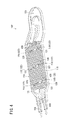
図1に示すように、燃料電池車両20は、基本的には、燃料電池22とエネルギストレージである蓄電装置(バッテリという。)24とから構成されるハイブリッド型の電源装置と、このハイブリッド型の電源装置から電流(電力)がインバータ34を通じて供給される走行用のモータ(電動機)26と、バッテリ24が接続される1次側1Sと燃料電池22とモータ26(インバータ34)とが接続される2次側2Sとの間で電圧変換を行うDC/DCコンバータ装置23とから構成される。バッテリ24は、電力線18を介してDC/DCコンバータ装置23の1次側1Sに接続される。
As shown in FIG. 1, the
モータ26の回転は、減速機12、シャフト14を通じて車輪16に伝達され、車輪16を回転させる。
The rotation of the
DC/DCコンバータ装置23は、DC/DCコンバータ(車両用DC/DCコンバータ)36と、これを駆動制御するコンバータ制御部54とから構成される。
The DC /
燃料電池22は、例えば固体高分子電解質膜をアノード電極とカソード電極とで両側から挟み込んで形成されたセルを積層したスタック構造にされている。燃料電池22には、水素タンク28とエアコンプレッサ30が配管により接続されている。燃料電池22内で反応ガスである水素(燃料ガス)と空気(酸化剤ガス)の電気化学反応により生成された発電電流Ifは、電流センサ32及びダイオード(ディスコネクトダイオードともいう。)33を介して、インバータ34及び(又は)DC/DCコンバータ36に供給される。
The
インバータ34は、直流/交流変換を行い、モータ電流Imをモータ26に供給する一方、回生動作に伴う交流/直流変換後のモータ電流Imを2次側2SからDC/DCコンバータ36を通じて1次側1Sに供給する。
The
この場合、回生電圧又は発電電圧Vfである2次電圧V2がDC/DCコンバータ36により低電圧の1次電圧V1に変換される。
In this case, the secondary voltage V2, which is the regenerative voltage or the generated voltage Vf, is converted into a low primary voltage V1 by the DC /
1次側1Sに接続されるバッテリ24は、例えばリチウムイオン2次電池又はキャパシタを利用することができる。この実施形態ではリチウムイオン2次電池を利用している。
As the
バッテリ24は、DC/DCコンバータ36を通じてインバータ34にモータ電流Imを供給する。
The
1次側1S及び2次側2Sには、それぞれ平滑用のコンデンサ38、39が設けられている。2次側2Sのコンデンサ39には、並列に、すなわち燃料電池22に対しても並列に、抵抗器40が接続されている。
燃料電池22を含むシステムはFC制御部50により制御され、インバータ34とモータ26を含むシステムはインバータ駆動部を含むモータ制御部52により制御され、DC/DCコンバータ36を含むシステムはコンバータ駆動部を含むコンバータ制御部54により、それぞれ基本的に制御される。
The system including the
そして、これらFC制御部50、モータ制御部52、及びコンバータ制御部54は、上位の制御部であり燃料電池22の総負荷量Lt等を決定する統括制御部56により制御される。これら統括制御部56、FC制御部50、モータ制御部52、及びコンバータ制御部54は、車内LANであるCAN(Controller Area Network)等の通信線70を通じて相互に接続され、各種スイッチ及び各種センサからの入出力情報を共有し、これら各種スイッチ及び各種センサからの入出力情報を入力として各CPUが各ROMに格納されたプログラムを実行することにより各種機能を実現する。
The
DC/DCコンバータ36は、第1の電力装置(バッテリ24)と第2の電力装置{燃料電池22又は回生電源(インバータ34とモータ26)}との間に、それぞれIGBT等のスイッチング素子からなる上アーム素子81{81u、81v、81w(81u〜81w)}と、下アーム素子82{82u、82v、82w(82u〜82w)}とからなる3つの相アーム{U相アームUA(81u、82u)、V相アームVA(81v、82v)、W相アームWA(81w、82w)}が並列的に接続された3相アームとして構成されている。
The DC /
各アーム素子81u、81v、81w、82u、82v、82wには、それぞれ、逆方向に並列にダイオード83u、83v、83w、84u、84v、84w(逆並列ダイオード)が接続されている。
DC/DCコンバータ36により1次電圧V1と2次電圧V2との間で電圧を変換する際に、エネルギを放出及び蓄積する1個のリアクトル90が、3相アームの各相のアーム(U相アームUA、V相アームVA、W相アームWA)の中点の共通接続点とバッテリ24との間に挿入されている。
When the voltage is converted between the primary voltage V1 and the secondary voltage V2 by the DC /
上アーム素子81(81u〜81w)は、コンバータ制御部54から出力されるゲートの駆動信号(駆動電圧)UH、VH、WH(のハイレベル)によりそれぞれオンにされ、下アーム素子82(82u〜82w)は、ゲートの駆動信号(駆動電圧)UL、VL、WL(のハイレベル)によりそれぞれオンにされる。
The upper arm elements 81 (81u to 81w) are turned on by gate drive signals (drive voltages) UH, VH, and WH (high levels thereof) output from the
ここで、コンバータ制御部54により駆動制御されるDC/DCコンバータ36の基本動作について説明する。
Here, the basic operation of the DC /
先ず、昇圧動作では、コンバータ制御部54は、下アーム素子82uをオンし、リアクトル90にバッテリ電流Ibat(1次電流I1)によりエネルギを蓄積すると同時に、コンデンサ39から2次電流I2をインバータ34へ供給する。次に、下アーム素子82uをオフにすると、ダイオード83u〜83wが導通してリアクトル90からエネルギが放出されコンデンサ39にエネルギが蓄積されると共に、2次電流I2がインバータ34へ供給される。以下、同様に、次に、下アーム素子82vをオンし、次に、下アーム素子82vをオフにしてダイオード83u〜83wを導通させる。次に、下アーム素子82wをオンし、次に、下アーム素子82wをオフにしてダイオード83u〜83wを導通させる。次に、下アーム素子82uをオンし、上記の順でDC/DCコンバータ36をローテーションスイッチングする。
First, in the step-up operation, the
なお、上アーム素子81u〜81w及び下アーム素子82u〜82wのオンデューティは、出力電圧V2が統括制御部56からの指令電圧に保持されるように決定される。
The on-duty of the
一方、DC/DCコンバータ36の2次側2Sから1次側1Sのバッテリ24に2次電流I2を供給する降圧動作では、上アーム素子81uをオンし、リアクトル90にコンデンサ39から出力される2次電流I2によりエネルギを蓄積すると共にコンデンサ38からバッテリ24に1次電流I1を供給する。次いで、上アーム素子81uをオフにすると、ダイオード84u〜84wがフライホイールダイオードとして導通し、リアクトル90からエネルギ放出され、コンデンサ38にエネルギを蓄積すると共にバッテリ24に1次電流I1を供給する。以下同様にして、上アーム素子81vオン→上アーム素子81vオフ→ダイオード84u〜84w導通→上アーム素子81wオン→上アーム素子81wオフ→ダイオード84u〜84w導通→上アーム素子81uオン…の順でDC/DCコンバータ36をローテーションスイッチングする。
On the other hand, in the step-down operation in which the secondary current I2 is supplied from the
以上が、コンバータ制御部54により駆動制御されるDC/DCコンバータ36の基本動作の説明である。
The above is the description of the basic operation of the DC /
図1、図2A及び図2Bに示すように、このようなDC/DCコンバータ36では、各アーム素子81u〜81w、82u〜82wと、これに対応する各ダイオード83u〜83w、84u〜84wとは、各組(例えば、上アーム素子81uとダイオード83uとで一組)ごとに集積された上チップ91{91u、91v、91w(91u〜91w)}及び下チップ92{92u、92v、92w(92u〜92w)}として構成されている。
As shown in FIGS. 1, 2A and 2B, in such a DC /
各上チップ91u〜91w及び各下チップ92u〜92wは、例えば、金属製(銅やアルミニウム等)からなる一枚(共通)の放熱板(ヒートスプレッダ)94上に、それぞれ絶縁基板96{96u、96v、96w(96u〜96w)}及び絶縁基板97{97u、97v、97w(97u〜97w)}を挟んで配列固着され、これらが一体的にモールドされたスイッチングモジュール98として構成されている(図2B及び図7参照)。
Each of the
すなわち、スイッチングモジュール98は、いわゆる6in1モジュールとして構成され、各アーム素子81u〜81w、82u〜82wのゲート端子がコンバータ制御部54に接続されている。
That is, the switching
次に、このようなDC/DCコンバータ36を冷却する冷却装置10について説明する。
Next, the
図3に示すように、冷却装置10は、扁平箱状のケーシング100と、該ケーシング100内に収容され、図示しない冷却液(例えば、水やクーラント)が流通される冷却液流路102とを備え、ケーシング100表面と冷却液流路102(冷却液)との間で高い伝熱性を有している。冷却液流路102は途中にU字状の折り返し部104を有し、ケーシング100の一側面に並設された入口ポート106及び出口ポート108を介して冷却液が直列に循環されることにより、ケーシング100上に放熱板94を介して密着配置されるスイッチングモジュール98を冷却することができる。
As shown in FIG. 3, the
図1に示すように、冷却液流路102には、入口ポート106及び出口ポート108を介して循環ポンプ110及びラジエータ112が接続されている。従って、循環ポンプ110の駆動作用下に、冷却液が冷却液流路102内を循環されると共に、出口ポート108から流出した冷却液は、ラジエータ112にて放熱し冷却された後、再び入口ポート106から冷却液流路102へと循環されてスイッチングモジュール98の冷却に供される。
As shown in FIG. 1, a
図4及び図5に示すように、冷却液流路102は、ラジエータ112で冷却された直後に入口ポート106から流入した冷却液が最初に流通する第1直線部(上直線部)114と、第1直線部114を通過した冷却液の流通方向を反転させる折り返し部104と、第1直線部114に並設され、折り返し部104を通過した冷却液が流通する第2直線部(下直線部)116とを有する。第2直線部116を通過した冷却液は、出口ポート108を介して再びラジエータ112へと送られる。このように、冷却液流路102では、第1直線部114及び第2直線部116を折り返し部104を介して並列することにより、全体構成を大幅に小型化すると共に、入口ポート106及び出口ポート108を並列可能であるため、燃料電池車両20への設置自由度を向上させている。
As shown in FIGS. 4 and 5, the
各直線部114、116には、冷却液の流通方向に延びた複数枚(本実施形態の場合、6枚)の冷却フィン(放熱フィン)120が設けられ、各冷却フィン120は、3つの切欠部(間隙部)118によって前記流通方向(長手方向)で4分割されている。冷却フィン120は、銅やアルミニウム等により形成された薄板からなり、スイッチングモジュール98からの熱を高効率に冷却液に伝達することができる。また、各冷却フィン120の前記流通方向端部には、湾曲したR部(R形状)121が形成されている。
Each of the
切欠部118は、冷却フィン120をその長手方向の所定位置で分割し、直線部114、116の途中に冷却フィン120が配置されない空間、すなわちチャンバー122を形成するものである。該切欠部118は、スイッチングモジュール98に設けられる各チップ91u〜91w、92u〜92wの配置間隔に対応して設けられる(図6参照)。つまり、各直線部114、116には、各チップ91u〜91w、92u〜92wに対応する位置にそれぞれ3つのチャンバー122が設けられている。
The
図6及び図7から諒解されるように、各チャンバー122は、冷却液の流通方向において、発熱体であるチップ91u〜91w、92u〜92wの中心部を通る中心線CLに対応する位置にそれぞれ設定されている。また、チャンバー122の高さHcは、冷却フィン120の高さHfより大きく設定され(Hc>Hf)、これにより、チャンバー122の容積を可及的に増大させている。チャンバー122の容積を拡大するために、該チャンバー122部分での幅方向(冷却液の流通方向に直交する方向)の寸法を拡大することも可能である。
As can be understood from FIGS. 6 and 7, each
図5中に破線で囲む参照符号124は、当該冷却液流路102を鋳造する際の砂抜き穴であり、該砂抜き穴124をチャンバー122に対応した位置とすると、チャンバー122の容積を一層増大させることができる。
なお、冷却装置10では、折り返し部104の上流側の第1直線部114側に、スイッチングモジュール98のうち、回生側の上チップ91u〜91wを配置し、折り返し部104の下流側の第2直線部116側に駆動側の下チップ92u〜92wを配置しているが、さらに、折り返し部104にリアクトル90を配置することもできる。そうすると、該リアクトル90の冷却のために別途冷却装置等を配置する必要がなく、すなわち、リアクトル90の冷却を同時に行うこともでき(図3及び図6参照)、折り返し部104のスペースを一層有効に活用することができる。
In the
次に、基本的には以上のように構成される本実施形態に係る燃料電池車両20の作用効果及び冷却装置10を用いたDC/DCコンバータの冷却方法について説明する。
Next, the operation effect of the
上記したように、冷却装置10では、スイッチングモジュール98を構成する各チップ91u〜91w、92u〜92wにそれぞれ対応する各直線部114、116に冷却フィン120を設けると共に、該冷却フィン120に切欠部118を設けてチャンバー122を形成している。このため、流通される冷却液を各冷却フィン120間の狭い流路から、広い空間であるチャンバー122内に流入させ、該チャンバー122内で冷却液の流れを乱すことができる(図8参照)。換言すれば、直線部114、116を流れる冷却液は、各冷却フィン120間では層流又は層流に近い整流された状態であり、チャンバー122内では乱流となる。これにより、チャンバー122内では、冷却液とスイッチングモジュール98との間の熱伝達率を大幅に向上させることができ、冷却装置10の冷却性能を向上させることができ、すなわち、所望の冷却性能に対して冷却装置10をより小型に構成することができる。
As described above, in the
また、チャンバー122の高さHcを冷却フィン120の高さHfより大きく設定することにより、冷却フィン120部分に比べて、当該チャンバー122の容積を可及的に大きくすることができる。これにより、冷却性能を一層高めることができ、しかも冷却液流路102の大型化を最小限に抑えることができる。
Further, by setting the height Hc of the
図6及び図7に示すように、発熱体であるチップ91u〜91w、92u〜92wの少なくとも冷却液の流通方向での中心部をチャンバー122に対応するように設定することにより、乱流発生位置であるチャンバー122を発熱体の直下とすることができる。このため、各チップ91u〜91w、92u〜92wで発生する熱を一層効率的に放熱させ、当該冷却装置10の冷却性能を一層向上させることができる。この場合、冷却液の流通方向での各チャンバー122の配置間隔は図6等に示すように必ずしも等間隔である必要はなく、発熱体であるチップ91u〜91w、92u〜92wの配置間隔に対応して適宜変更可能である。
As shown in FIGS. 6 and 7, by setting at least the center of the
なお、前記の発熱体の少なくとも冷却液の流通方向での中心部をチャンバー122に対応するように設定するとは、発熱体であるチップ91u〜91w、92u〜92wの中心部を通る中心線CLがチャンバー122内に位置していればよく、当然、中心線CLの位置を図7中の中心線CL1又はCL2等の位置としてもよい。さらには、前記の発熱体の少なくとも冷却液の流通方向での中心部をチャンバー122に対応するように設定するとは、発熱体であるチップ91u〜91w、92u〜92wにおいて最も発熱を生じる素子の中心部ともいうことができ、例えば、スイッチング素子であるアーム素子81u〜81w、82u〜82w又はダイオード83u〜83w、84u〜84wのうち、最も発熱するか又は冷却を必要とするものの中心部がチャンバー122に対応する位置としてもよい。
Note that setting at least the center of the heating element in the flow direction of the coolant to correspond to the
また、冷却装置10では、各切欠部118に対応する各冷却フィン120の端部にはR部121が形成されている。このため、チャンバー122内から冷却フィン120間へと冷却液を円滑に流入させることができ、エッジ形状とした上記従来構成のように大きな圧力損失を生じることがない。従って、冷却液流路102での冷却液の円滑な流通とこれによる冷却性能の向上を図ることができる。さらに、循環ポンプ110の負荷を低減することができるため、当該循環ポンプ110を小型化することができ、冷却装置10の小型・軽量化や車両での設置自由度の向上が可能となる。
In the
さらに、図6に示すように、スイッチングモジュール98のケーシング100への当接側面には、ヒートスプレッダである放熱板94が配置され、発熱体であるチップ91u〜91w、92u〜92wは共通の放熱板94上に配置されている。これにより、最も発熱量の高いチップ91u〜91w、92u〜92wの直下にはチャンバー122を設定しつつ、放熱板94に拡散されたチップ91u〜91w、92u〜92wからの熱が当該放熱板94を介して冷却フィン120側へと効率的に放熱される。すなわち、各チップ91u〜91w、92u〜92wからの熱をより広い面積で冷却液と熱交換させることが可能となり、冷却装置10の冷却性能を一層向上させることができる。
Further, as shown in FIG. 6, a
ところで、このような冷却装置10によって冷却するDC/DCコンバータ36において、スイッチングモジュール98を構成する上チップ91u〜91wと下チップ92u〜92wとの間では、その発熱量に差異を生じることがあり、通常、駆動側となる下チップ92u〜92wより回生側となる上チップ91u〜91wの発熱量が大きくなる。
By the way, in the DC /
燃料電池車両20では、例えば、燃料電池22は高出力時に端子間電圧が下がってしまう特性があるため、車両として回生と駆動では同じ出力を行ったとしても、スイッチング素子であるアーム素子81u〜81w、82u〜82wの1次側1Sと2次側2Sの電圧差は、駆動時に比べてモータ逆起電圧の影響を受ける回生時の方が大きくなり、このためスイッチング損失が大きくなる。従って、例えば、回生側(上チップ91u〜91w)と駆動側(下チップ92u〜92w)とを、同一の冷却設計とした場合には、回生側の方が熱的に厳しく、回生量を駆動側と同等に得ることができない。
In the
そこで、本実施形態に係る車両用DC/DCコンバータの冷却方法によれば、冷却装置10において、折り返し部104の上流側の第1直線部114側に上チップ91u〜91wを配置し、折り返し部104の下流側の第2直線部116側に下チップ92u〜92wを配置するように構成している。すなわち、冷却液流路102では、冷却液を発熱量(熱負荷)の大きな回生側である上アーム素子81u〜81w側に流した後、折り返し部104を介して駆動側である下アーム素子82u〜82w側へと直列に流すことにより、発熱量の大きい回生側を先に冷却し、上アーム素子81u〜81wが過熱されることを防止して最大出力及び該最大出力を発生させておくことが可能な時間を最大限利用することができる。
Therefore, according to the cooling method for a DC / DC converter for a vehicle according to the present embodiment, in the
従って、回生時におけるDC/DCコンバータ36の冷却性能を有効に向上させることができ、燃料電池車両20の回生可能電力量を増加させることができる。
Therefore, the cooling performance of the DC /
また、冷却液流路102では、第1直線部114から折り返し部104を介して第2直線部116へと連続するUターン構造としているため、入口ポート106及び出口ポート108を当該冷却装置10の一側面側にまとめることができる。このため、冷却装置10の一層の小型化を図ることができると共に、循環ポンプ110やラジエータ112への配管を一層容易に且つ簡素にすることができる。冷却液流路102では、このような折り返し部104によるUターン構造以外にも、車載時の設置スペース等を考慮して適宜直線状や曲線状等からなる流路構成とすることもできる。
In addition, since the
なお、図9に示すように、本実施形態に係る電気車両である燃料電池車両20は、燃料電池22及びその関連部品を省略すると共に、エンジン(内燃機関)130を設け、該エンジン130の出力軸をモータ26及び減速機12に連結した電気車両20aとして構成することもできる。すなわち、電気車両20aは、いわゆるパラレル方式のハイブリッド車両として構成されている。
As shown in FIG. 9, the
さらに、図10に示すように、燃料電池車両20から燃料電池22及びその関連部品を省略すると共に、エンジン130及び発電機132を設け、エンジン130の出力軸を発電機132及び減速機12に連結すると共に、発電機132とモータ26とを電気的に接続した電気車両20bとして構成することもできる。すなわち、電気車両20bは、いわゆるシリーズ・パラレル方式のハイブリッド車両として構成されている。なお、当該電気車両20bにおいて、エンジン130の出力軸を発電機132にのみ連結し、減速機12への連結を省略又は減速機12自体を省略した場合には、いわゆるシリーズ方式のハイブリッド車両を構成することができる。
Further, as shown in FIG. 10, the
なお、本実施形態に係る電気車両である燃料電池車両20から燃料電池22及びその関連部品を省略してエンジン130等を追加しない電気車両として構成してもよいことは言うまでもない。
It goes without saying that the
本発明は、上述の実施の形態に限らず、本発明の要旨を逸脱することなく、種々の構成を採り得ることはもちろんである。 The present invention is not limited to the above-described embodiment, and it goes without saying that various configurations can be adopted without departing from the gist of the present invention.
10…冷却装置 20…燃料電池車両
20a、20b…電気車両 22…燃料電池
23…DC/DCコンバータ装置 24…蓄電装置
26…モータ 34…インバータ
36…DC/DCコンバータ 91、91u〜91w…上チップ
92、92u〜92w…下チップ 94…放熱板
98…スイッチングモジュール 100…ケーシング
102…冷却液流路 104…折り返し部
106…入口ポート 108…出口ポート
118…切欠部 120…冷却フィン
121…R部 122…チャンバー
DESCRIPTION OF
Claims (5)
前記電動機に電力を並列的に供給する発電装置及び蓄電装置と、
前記蓄電装置と前記発電装置との間に接続され前記蓄電装置に発生する電圧を変換して前記電動機側に印加すると共に前記電動機の回生動作による回生電圧又は前記発電装置の発電電圧を変換して前記蓄電装置側に印加するDC/DCコンバータと、
冷却液が流通されると共に、一部に折り返し部が形成された冷却液流路を有し、前記DC/DCコンバータを冷却する冷却装置と、
を備え、
前記DC/DCコンバータは、前記蓄電装置と前記電動機側との間に、少なくとも1組の上アーム素子と下アーム素子からなる相アーム素子を有し、
前記冷却装置は、前記折り返し部の上流側の前記冷却液で前記上アーム素子を冷却すると共に、前記折り返し部の下流側の前記冷却液で前記下アーム素子を冷却するように形成されていることを特徴とする電気車両。 An electric motor that rotates the wheels;
A power generation device and a power storage device for supplying electric power to the electric motor in parallel;
A voltage generated between the power storage device and the power generation device connected between the power storage device and the power generation device is converted and applied to the motor side, and a regenerative voltage generated by the regenerative operation of the motor or a power generation voltage of the power generation device is converted. A DC / DC converter applied to the power storage device side;
A cooling device that circulates the cooling liquid and has a cooling liquid flow path partially formed with a folded portion, and cools the DC / DC converter;
With
The DC / DC converter has a phase arm element including at least one set of an upper arm element and a lower arm element between the power storage device and the motor side,
The cooling device is configured to cool the upper arm element with the coolant upstream of the folded portion and to cool the lower arm element with the coolant downstream of the folded portion. An electric vehicle characterized by.
前記DC/DCコンバータは、前記蓄電装置と前記電動機側との間で電圧を変換する際に、エネルギを放出及び蓄積するリアクトルを有し、
前記冷却装置は、前記折り返し部の前記冷却液で前記リアクトルを冷却するように形成されていることを特徴とする電気車両。 The electric vehicle according to claim 1,
The DC / DC converter has a reactor that releases and stores energy when converting a voltage between the power storage device and the electric motor side,
The electric vehicle according to claim 1, wherein the cooling device is formed so as to cool the reactor with the coolant of the folded portion.
前記発電装置は燃料電池であることを特徴とする電気車両。 The electric vehicle according to claim 1 or 2,
The electric vehicle is a fuel cell.
前記電動機に電力を供給する蓄電装置と、
前記蓄電装置と前記電動機との間に接続され前記蓄電装置に発生する電圧を変換して前記電動機側に印加すると共に前記電動機の回生動作による回生電圧を変換して前記蓄電装置側に印加するDC/DCコンバータと、
冷却液が流通されると共に、一部に折り返し部が形成された冷却液流路を有し、前記DC/DCコンバータを冷却する冷却装置と、
を備え、
前記DC/DCコンバータは、前記蓄電装置と前記電動機側との間に、少なくとも1組の上アーム素子と下アーム素子からなる相アーム素子を有し、
前記冷却装置は、前記折り返し部の上流側の前記冷却液で前記上アーム素子を冷却すると共に、前記折り返し部の下流側の前記冷却液で前記下アーム素子を冷却するように形成されていることを特徴とする電気車両。 An electric motor that rotates the wheels;
A power storage device for supplying electric power to the electric motor;
DC which is connected between the power storage device and the electric motor, converts a voltage generated in the power storage device and applies it to the motor side, and converts a regenerative voltage generated by a regenerative operation of the motor and applies it to the power storage device side / DC converter,
A cooling device that circulates the cooling liquid and has a cooling liquid flow path partially formed with a folded portion, and cools the DC / DC converter;
With
The DC / DC converter has a phase arm element including at least one set of an upper arm element and a lower arm element between the power storage device and the motor side,
The cooling device is configured to cool the upper arm element with the coolant upstream of the folded portion and to cool the lower arm element with the coolant downstream of the folded portion. An electric vehicle characterized by.
前記DC/DCコンバータを冷却する冷却液が流通される冷却液流路の途中に折り返し部を設け、
前記折り返し部の上流側の前記冷却液で前記上アーム素子を冷却すると共に、前記折り返し部の下流側の前記冷却液で前記下アーム素子を冷却することを特徴とする車両用DC/DCコンバータの冷却方法。 Vehicle for cooling a DC / DC converter connected between an electric motor for rotating a wheel and a power storage device for supplying electric power to the electric motor and having a phase arm element composed of at least one upper arm element and lower arm element A cooling method for a DC / DC converter for a vehicle,
A folded portion is provided in the middle of the coolant flow path through which the coolant for cooling the DC / DC converter flows.
The vehicular DC / DC converter characterized in that the upper arm element is cooled with the coolant upstream of the folded portion and the lower arm element is cooled with the coolant downstream of the folded portion. Cooling method.
Priority Applications (5)
| Application Number | Priority Date | Filing Date | Title |
|---|---|---|---|
| JP2008026445A JP4819071B2 (en) | 2008-02-06 | 2008-02-06 | Electric vehicle and cooling method for DC / DC converter for vehicle |
| US12/521,674 US8159823B2 (en) | 2008-02-06 | 2009-01-22 | Electric vehicle and method of cooling vehicular DC/DC converter |
| EP09700064A EP2432106A4 (en) | 2008-02-06 | 2009-01-22 | Electric vehicle, and method for cooling vehicular dc/dc-converter |
| PCT/JP2009/051002 WO2009098948A1 (en) | 2008-02-06 | 2009-01-22 | Electric vehicle, and method for cooling vehicular dc/dc-converter |
| CN2009800000668A CN101689804B (en) | 2008-02-06 | 2009-01-22 | Electric vehicle, and method for cooling vehicular dc/dc-converter |
Applications Claiming Priority (1)
| Application Number | Priority Date | Filing Date | Title |
|---|---|---|---|
| JP2008026445A JP4819071B2 (en) | 2008-02-06 | 2008-02-06 | Electric vehicle and cooling method for DC / DC converter for vehicle |
Publications (2)
| Publication Number | Publication Date |
|---|---|
| JP2009189149A JP2009189149A (en) | 2009-08-20 |
| JP4819071B2 true JP4819071B2 (en) | 2011-11-16 |
Family
ID=40952026
Family Applications (1)
| Application Number | Title | Priority Date | Filing Date |
|---|---|---|---|
| JP2008026445A Expired - Fee Related JP4819071B2 (en) | 2008-02-06 | 2008-02-06 | Electric vehicle and cooling method for DC / DC converter for vehicle |
Country Status (5)
| Country | Link |
|---|---|
| US (1) | US8159823B2 (en) |
| EP (1) | EP2432106A4 (en) |
| JP (1) | JP4819071B2 (en) |
| CN (1) | CN101689804B (en) |
| WO (1) | WO2009098948A1 (en) |
Families Citing this family (70)
| Publication number | Priority date | Publication date | Assignee | Title |
|---|---|---|---|---|
| JP4850564B2 (en) * | 2006-04-06 | 2012-01-11 | 日立オートモティブシステムズ株式会社 | Power converter |
| JP4436843B2 (en) | 2007-02-07 | 2010-03-24 | 株式会社日立製作所 | Power converter |
| EP2277365B1 (en) * | 2008-05-16 | 2011-11-02 | Parker-Hannifin Corporation | Modular high-power drive stack cooled with vaporizable dielectric fluid |
| JP4775475B2 (en) * | 2009-04-14 | 2011-09-21 | 株式会社デンソー | Power converter |
| KR101289313B1 (en) * | 2009-05-22 | 2013-07-24 | 엘에스산전 주식회사 | Water-cooling type cooler and inverter having the same |
| EP2299582B1 (en) * | 2009-09-18 | 2015-03-11 | SMA Solar Technology AG | Inverter with a housing and electric and electronic components assembled within same |
| DE102010004713A1 (en) * | 2010-01-11 | 2011-07-14 | Dr. Ing. h.c. F. Porsche Aktiengesellschaft, 70435 | Hybrid drive of a hybrid vehicle |
| EP2523822B1 (en) * | 2010-01-15 | 2017-02-08 | MAGNA STEYR Engineering AG & Co KG | Energy transmission strand |
| JP5702988B2 (en) * | 2010-01-29 | 2015-04-15 | 株式会社 日立パワーデバイス | SEMICONDUCTOR POWER MODULE, POWER CONVERSION DEVICE MOUNTED WITH THE SEMICONDUCTOR POWER MODULE, AND METHOD FOR MANUFACTURING SEMICONDUCTOR POWER MODULE WATER CHANNEL FORMING BODY |
| WO2011125784A1 (en) * | 2010-03-31 | 2011-10-13 | 株式会社 東芝 | Electric vehicle control device |
| JP5563383B2 (en) * | 2010-06-21 | 2014-07-30 | 日立オートモティブシステムズ株式会社 | Power converter |
| CN102958745B (en) * | 2010-06-29 | 2015-07-08 | 本田技研工业株式会社 | Electric automobile |
| US20130003301A1 (en) * | 2010-11-24 | 2013-01-03 | Toyota Jidosha Kabushiki Kaisha | Stacked cooler |
| EP2698590B1 (en) * | 2011-04-13 | 2016-11-30 | Nec Corporation | Piping structure of cooling device, manufacturing method thereof, and pipe coupling method. |
| WO2013039026A1 (en) * | 2011-09-15 | 2013-03-21 | 住友重機械工業株式会社 | Work machine |
| TWM422285U (en) * | 2011-09-21 | 2012-02-01 | Enermax Technology Corp | Liquid-cooling type improved heat exchange module |
| JP5790394B2 (en) * | 2011-10-14 | 2015-10-07 | トヨタ自動車株式会社 | Electric car |
| WO2013084278A1 (en) * | 2011-12-05 | 2013-06-13 | トヨタ自動車株式会社 | Fuel cell vehicle |
| KR20130085325A (en) * | 2012-01-19 | 2013-07-29 | 삼성전자주식회사 | Fuel cell system and method for operating the same at low temperature |
| JP2013165607A (en) * | 2012-02-13 | 2013-08-22 | Hitachi Constr Mach Co Ltd | Power conversion device of work vehicle |
| WO2013140502A1 (en) * | 2012-03-19 | 2013-09-26 | 三菱電機株式会社 | Power conversion apparatus |
| CN103368359B (en) * | 2012-04-11 | 2016-04-13 | 台达电子工业股份有限公司 | Current transformer power unit and bus bar thereof |
| US9020674B2 (en) | 2012-04-13 | 2015-04-28 | Toyota Motor Engineering & Manufacturing North America, Inc. | Diversion of energy from regenerative braking |
| KR101431550B1 (en) | 2012-07-03 | 2014-10-06 | (주)인벤티오 | Apparatus for cooling battery and method of producing the same |
| EP2719985B1 (en) * | 2012-10-09 | 2015-08-26 | Danfoss Silicon Power GmbH | A flow distribution module with a patterned cover plate |
| TWI482244B (en) * | 2012-11-19 | 2015-04-21 | Ind Tech Res Inst | Heat exchanger and semiconductor module |
| US9578788B2 (en) * | 2013-03-15 | 2017-02-21 | Atieva, Inc. | Inverter power module packaging with cold plate |
| JP5955262B2 (en) * | 2013-04-24 | 2016-07-20 | 三菱電機株式会社 | Semiconductor cooling device |
| DE102013209409A1 (en) | 2013-05-22 | 2014-11-27 | Siemens Aktiengesellschaft | DC-DC converter and fuel cell system of a submarine |
| US9485889B2 (en) * | 2013-08-15 | 2016-11-01 | Eaton Corporation | Medium voltage hybrid air/liquid cooled adjustable frequency drive |
| CN104617064B (en) * | 2013-11-04 | 2017-05-10 | 江苏宏微科技股份有限公司 | Stack-up power module |
| JP6504832B2 (en) * | 2014-01-28 | 2019-04-24 | ゼネラル・エレクトリック・カンパニイ | Integrated mounting and cooling devices, electronic devices and vehicles |
| US20160021784A1 (en) * | 2014-07-15 | 2016-01-21 | Caterpillar Inc. | Cooling Module for Electrical Components |
| WO2016041145A1 (en) * | 2014-09-16 | 2016-03-24 | 深圳市大疆创新科技有限公司 | Heat dissipation apparatus and uav using heat dissipation apparatus |
| US10317960B2 (en) * | 2014-09-28 | 2019-06-11 | Intel Corporation | Passive radiator cooling for electronic devices |
| DE102015201440A1 (en) * | 2015-01-28 | 2016-07-28 | Bayerische Motoren Werke Aktiengesellschaft | Supply rail for a motor vehicle |
| CN106068603B (en) * | 2015-02-23 | 2018-09-28 | 三菱电机株式会社 | Semi-conductor electricity force transducer |
| JP6292154B2 (en) | 2015-03-19 | 2018-03-14 | トヨタ自動車株式会社 | Power system |
| US9848519B2 (en) | 2015-04-15 | 2017-12-19 | Ford Global Technologies, Llc | Power module assembly and manifold |
| TWI562512B (en) * | 2015-05-20 | 2016-12-11 | Genius Electronic Optical Co Ltd | Water cooling power supply device applicable to open water source |
| CN104960411B (en) * | 2015-05-21 | 2017-11-03 | 北京车和家信息技术有限公司 | For the cooling recirculation system of electric vehicle and the electric vehicle with it |
| FR3043880B1 (en) * | 2015-11-13 | 2017-12-29 | Valeo Systemes De Controle Moteur | HOUSING FOR ELECTRICAL EQUIPMENT |
| JP6540496B2 (en) * | 2015-12-17 | 2019-07-10 | 株式会社デンソー | Power converter |
| JP6623810B2 (en) * | 2016-02-16 | 2019-12-25 | オムロン株式会社 | Cooler, flow path unit |
| JP6390638B2 (en) | 2016-02-25 | 2018-09-19 | トヨタ自動車株式会社 | Fuel cell vehicle equipped with a reactor unit and a reactor unit |
| JP6768340B2 (en) * | 2016-04-28 | 2020-10-14 | 株式会社東芝 | Railway vehicle power converter |
| KR20180016102A (en) * | 2016-08-05 | 2018-02-14 | 엘지이노텍 주식회사 | Electronic component package |
| JP6191745B1 (en) * | 2016-08-10 | 2017-09-06 | 富士電機株式会社 | Uninterruptible power system |
| US9955613B2 (en) * | 2016-09-13 | 2018-04-24 | Denso International America, Inc. | Cooler and power electronic module having the same |
| WO2018055923A1 (en) * | 2016-09-23 | 2018-03-29 | 住友精密工業株式会社 | Cooling device |
| CN108738368B (en) * | 2017-02-13 | 2022-06-17 | 新电元工业株式会社 | Electronic device |
| JP6944251B2 (en) * | 2017-02-27 | 2021-10-06 | 川崎重工業株式会社 | control panel |
| US11667202B2 (en) | 2017-03-08 | 2023-06-06 | A3 Labs LLC | Energy source supply systems, energy source supply devices, and related methods |
| CN110383470B (en) * | 2017-03-16 | 2023-05-09 | 三菱电机株式会社 | Cooling system |
| CN107317065B (en) * | 2017-06-23 | 2023-04-25 | 东风商用车有限公司 | TEC-based power battery thermal management system and control method thereof |
| JP6888468B2 (en) * | 2017-08-01 | 2021-06-16 | 富士電機株式会社 | Power converter for railroad vehicles |
| US11557521B2 (en) * | 2017-10-26 | 2023-01-17 | Mitsubishi Electric Corporation | Heat sink and circuit device |
| JP6954029B2 (en) * | 2017-11-15 | 2021-10-27 | 富士電機株式会社 | Power converters and rail vehicle power converters |
| JP6988432B2 (en) * | 2017-12-18 | 2022-01-05 | 株式会社デンソー | Reactor unit |
| US10804547B2 (en) | 2018-01-10 | 2020-10-13 | Cummins Enterprise Llc | Power generation system and a method for operating the same |
| CN108482172B (en) * | 2018-05-23 | 2024-01-02 | 威腾电气集团股份有限公司 | Three-in-one vehicle-mounted DCDC integrated power supply |
| EP3643547B1 (en) | 2018-10-26 | 2023-09-06 | Mahle International GmbH | Electric power converter device |
| EP3684154B1 (en) * | 2019-01-21 | 2024-03-06 | Aptiv Technologies Limited | Thermally conductive insert element for electronic unit |
| CA3141643A1 (en) * | 2019-03-18 | 2020-09-24 | dcbel Inc. | Cooling system for use in power converters |
| JP7393941B2 (en) | 2019-12-25 | 2023-12-07 | 株式会社Soken | power conversion system |
| KR20220001196A (en) * | 2020-06-29 | 2022-01-05 | 에스케이하이닉스 주식회사 | Liquid cooling structure and liquid cooling system having the same |
| US11502349B2 (en) | 2020-08-31 | 2022-11-15 | Borgwarner, Inc. | Cooling manifold assembly |
| US11525638B2 (en) * | 2020-10-19 | 2022-12-13 | Dana Canada Corporation | High-performance heat exchanger with calibrated bypass |
| DE102020213629A1 (en) * | 2020-10-29 | 2022-05-05 | Valeo Siemens Eautomotive Germany Gmbh | Power module and power electronic device |
| US11740028B2 (en) * | 2021-06-18 | 2023-08-29 | Dana Canada Corporation | Two-pass heat exchanger with calibrated bypass |
Family Cites Families (17)
| Publication number | Priority date | Publication date | Assignee | Title |
|---|---|---|---|---|
| DE3133485A1 (en) * | 1980-09-15 | 1982-05-06 | Peter 2563 Ipsach Herren | LIQUID-COOLED ELECTRICAL ASSEMBLY |
| JP3800938B2 (en) | 2000-09-13 | 2006-07-26 | 日産自動車株式会社 | Power module cooling device |
| JP3912249B2 (en) * | 2002-09-30 | 2007-05-09 | 日本電気株式会社 | Fuel cell operation method and portable device equipped with fuel cell |
| JP2004201463A (en) * | 2002-12-20 | 2004-07-15 | Toyota Motor Corp | Voltage conversion device, anomaly detecting method, and computer-readable recording medium with program recorded thereon for causing computer to carry out anomaly detection |
| EP1588889B1 (en) * | 2004-04-21 | 2016-11-23 | MICHELIN Recherche et Technique S.A. | Electric traction assembly for fuel cell vehicle having an electric resistor for heat dissipation |
| JP2005332863A (en) * | 2004-05-18 | 2005-12-02 | Denso Corp | Power stack |
| JP2005346948A (en) * | 2004-05-31 | 2005-12-15 | Nissan Motor Co Ltd | Fuel cell system |
| US7289329B2 (en) * | 2004-06-04 | 2007-10-30 | Siemens Vdo Automotive Corporation | Integration of planar transformer and/or planar inductor with power switches in power converter |
| JP2005353410A (en) * | 2004-06-10 | 2005-12-22 | Toyota Motor Corp | Cooling device for fuel cell, and vehicle with the same mounted thereon |
| US7835151B2 (en) * | 2004-11-24 | 2010-11-16 | Danfoss Silicon Power Gmbh | Flow distribution module and a stack of flow distribution modules |
| JP2006190972A (en) * | 2004-12-08 | 2006-07-20 | Mitsubishi Electric Corp | Power semiconductor device |
| US7210304B2 (en) * | 2005-02-09 | 2007-05-01 | General Motors Corporation | Cooling arrangements for integrated electric motor-inverters |
| JP4555136B2 (en) * | 2005-03-31 | 2010-09-29 | 本田技研工業株式会社 | Fuel cell electrical system, fuel cell vehicle and power supply method |
| JPWO2007064020A1 (en) * | 2005-11-29 | 2009-05-07 | トヨタ自動車株式会社 | DC-DC converter for electric vehicles |
| JP4848187B2 (en) * | 2006-01-17 | 2011-12-28 | 日立オートモティブシステムズ株式会社 | Power converter |
| US20070165376A1 (en) * | 2006-01-17 | 2007-07-19 | Norbert Bones | Three phase inverter power stage and assembly |
| JP4434181B2 (en) * | 2006-07-21 | 2010-03-17 | 株式会社日立製作所 | Power converter |
-
2008
- 2008-02-06 JP JP2008026445A patent/JP4819071B2/en not_active Expired - Fee Related
-
2009
- 2009-01-22 EP EP09700064A patent/EP2432106A4/en not_active Withdrawn
- 2009-01-22 WO PCT/JP2009/051002 patent/WO2009098948A1/en active Application Filing
- 2009-01-22 US US12/521,674 patent/US8159823B2/en active Active
- 2009-01-22 CN CN2009800000668A patent/CN101689804B/en not_active Expired - Fee Related
Also Published As
| Publication number | Publication date |
|---|---|
| CN101689804A (en) | 2010-03-31 |
| CN101689804B (en) | 2012-12-26 |
| JP2009189149A (en) | 2009-08-20 |
| WO2009098948A1 (en) | 2009-08-13 |
| EP2432106A4 (en) | 2012-12-26 |
| US8159823B2 (en) | 2012-04-17 |
| EP2432106A1 (en) | 2012-03-21 |
| US20100315780A1 (en) | 2010-12-16 |
Similar Documents
| Publication | Publication Date | Title |
|---|---|---|
| JP4819071B2 (en) | Electric vehicle and cooling method for DC / DC converter for vehicle | |
| JP4785878B2 (en) | Cooling device and electric vehicle equipped with the cooling device | |
| JP4770490B2 (en) | Power semiconductor element cooling structure and inverter | |
| JP5423877B2 (en) | Stacked cooler | |
| JP4506848B2 (en) | Semiconductor module | |
| JP5099431B2 (en) | Inverter unit | |
| JP4529706B2 (en) | Semiconductor device and load driving device | |
| CN107123840B (en) | Reactor unit and fuel cell vehicle provided with reactor unit | |
| CN103026605A (en) | Power converter | |
| WO2008041761A1 (en) | Vehicle drive device | |
| JP2005323455A (en) | Drive system for vehicle | |
| JP4600052B2 (en) | Semiconductor device | |
| JP3800938B2 (en) | Power module cooling device | |
| JP2017103990A (en) | Vehicle with motor for running | |
| JP2011003288A (en) | Fuel cell system | |
| JP6943212B2 (en) | Power converter | |
| JP2009095102A (en) | Bus bar structure and power conversion device using the same | |
| JP4222193B2 (en) | Semiconductor device | |
| JP6350330B2 (en) | Power converter | |
| JP7279426B2 (en) | power converter | |
| JP2013016634A (en) | Cooling structure of semiconductor element | |
| JP2022042370A (en) | Electric power conversion system | |
| CN116031433A (en) | Fuel cell unit | |
| JP2024008693A (en) | fuel cell unit | |
| JP2020150788A (en) | Power conversion unit |
Legal Events
| Date | Code | Title | Description |
|---|---|---|---|
| TRDD | Decision of grant or rejection written | ||
| A01 | Written decision to grant a patent or to grant a registration (utility model) |
Free format text: JAPANESE INTERMEDIATE CODE: A01 Effective date: 20110802 |
|
| A01 | Written decision to grant a patent or to grant a registration (utility model) |
Free format text: JAPANESE INTERMEDIATE CODE: A01 |
|
| A61 | First payment of annual fees (during grant procedure) |
Free format text: JAPANESE INTERMEDIATE CODE: A61 Effective date: 20110831 |
|
| FPAY | Renewal fee payment (event date is renewal date of database) |
Free format text: PAYMENT UNTIL: 20140909 Year of fee payment: 3 |
|
| R150 | Certificate of patent or registration of utility model |
Free format text: JAPANESE INTERMEDIATE CODE: R150 |
|
| LAPS | Cancellation because of no payment of annual fees |