JP6540496B2 - Power converter - Google Patents
Power converter Download PDFInfo
- Publication number
- JP6540496B2 JP6540496B2 JP2015246440A JP2015246440A JP6540496B2 JP 6540496 B2 JP6540496 B2 JP 6540496B2 JP 2015246440 A JP2015246440 A JP 2015246440A JP 2015246440 A JP2015246440 A JP 2015246440A JP 6540496 B2 JP6540496 B2 JP 6540496B2
- Authority
- JP
- Japan
- Prior art keywords
- heat
- refrigerant
- generating component
- partition
- flow path
- Prior art date
- Legal status (The legal status is an assumption and is not a legal conclusion. Google has not performed a legal analysis and makes no representation as to the accuracy of the status listed.)
- Active
Links
Images


Classifications
-
- H—ELECTRICITY
- H02—GENERATION; CONVERSION OR DISTRIBUTION OF ELECTRIC POWER
- H02M—APPARATUS FOR CONVERSION BETWEEN AC AND AC, BETWEEN AC AND DC, OR BETWEEN DC AND DC, AND FOR USE WITH MAINS OR SIMILAR POWER SUPPLY SYSTEMS; CONVERSION OF DC OR AC INPUT POWER INTO SURGE OUTPUT POWER; CONTROL OR REGULATION THEREOF
- H02M7/00—Conversion of ac power input into dc power output; Conversion of dc power input into ac power output
- H02M7/003—Constructional details, e.g. physical layout, assembly, wiring or busbar connections
-
- H—ELECTRICITY
- H02—GENERATION; CONVERSION OR DISTRIBUTION OF ELECTRIC POWER
- H02M—APPARATUS FOR CONVERSION BETWEEN AC AND AC, BETWEEN AC AND DC, OR BETWEEN DC AND DC, AND FOR USE WITH MAINS OR SIMILAR POWER SUPPLY SYSTEMS; CONVERSION OF DC OR AC INPUT POWER INTO SURGE OUTPUT POWER; CONTROL OR REGULATION THEREOF
- H02M7/00—Conversion of ac power input into dc power output; Conversion of dc power input into ac power output
- H02M7/42—Conversion of dc power input into ac power output without possibility of reversal
- H02M7/44—Conversion of dc power input into ac power output without possibility of reversal by static converters
- H02M7/48—Conversion of dc power input into ac power output without possibility of reversal by static converters using discharge tubes with control electrode or semiconductor devices with control electrode
- H02M7/53—Conversion of dc power input into ac power output without possibility of reversal by static converters using discharge tubes with control electrode or semiconductor devices with control electrode using devices of a triode or transistor type requiring continuous application of a control signal
- H02M7/537—Conversion of dc power input into ac power output without possibility of reversal by static converters using discharge tubes with control electrode or semiconductor devices with control electrode using devices of a triode or transistor type requiring continuous application of a control signal using semiconductor devices only, e.g. single switched pulse inverters
-
- H—ELECTRICITY
- H05—ELECTRIC TECHNIQUES NOT OTHERWISE PROVIDED FOR
- H05K—PRINTED CIRCUITS; CASINGS OR CONSTRUCTIONAL DETAILS OF ELECTRIC APPARATUS; MANUFACTURE OF ASSEMBLAGES OF ELECTRICAL COMPONENTS
- H05K7/00—Constructional details common to different types of electric apparatus
- H05K7/20—Modifications to facilitate cooling, ventilating, or heating
- H05K7/20218—Modifications to facilitate cooling, ventilating, or heating using a liquid coolant without phase change in electronic enclosures
- H05K7/20254—Cold plates transferring heat from heat source to coolant
-
- H—ELECTRICITY
- H05—ELECTRIC TECHNIQUES NOT OTHERWISE PROVIDED FOR
- H05K—PRINTED CIRCUITS; CASINGS OR CONSTRUCTIONAL DETAILS OF ELECTRIC APPARATUS; MANUFACTURE OF ASSEMBLAGES OF ELECTRICAL COMPONENTS
- H05K7/00—Constructional details common to different types of electric apparatus
- H05K7/20—Modifications to facilitate cooling, ventilating, or heating
- H05K7/20218—Modifications to facilitate cooling, ventilating, or heating using a liquid coolant without phase change in electronic enclosures
- H05K7/20263—Heat dissipaters releasing heat from coolant
-
- H—ELECTRICITY
- H05—ELECTRIC TECHNIQUES NOT OTHERWISE PROVIDED FOR
- H05K—PRINTED CIRCUITS; CASINGS OR CONSTRUCTIONAL DETAILS OF ELECTRIC APPARATUS; MANUFACTURE OF ASSEMBLAGES OF ELECTRICAL COMPONENTS
- H05K7/00—Constructional details common to different types of electric apparatus
- H05K7/20—Modifications to facilitate cooling, ventilating, or heating
- H05K7/2089—Modifications to facilitate cooling, ventilating, or heating for power electronics, e.g. for inverters for controlling motor
- H05K7/209—Heat transfer by conduction from internal heat source to heat radiating structure
-
- H—ELECTRICITY
- H05—ELECTRIC TECHNIQUES NOT OTHERWISE PROVIDED FOR
- H05K—PRINTED CIRCUITS; CASINGS OR CONSTRUCTIONAL DETAILS OF ELECTRIC APPARATUS; MANUFACTURE OF ASSEMBLAGES OF ELECTRICAL COMPONENTS
- H05K7/00—Constructional details common to different types of electric apparatus
- H05K7/20—Modifications to facilitate cooling, ventilating, or heating
- H05K7/2089—Modifications to facilitate cooling, ventilating, or heating for power electronics, e.g. for inverters for controlling motor
- H05K7/20927—Liquid coolant without phase change
Landscapes
- Engineering & Computer Science (AREA)
- Microelectronics & Electronic Packaging (AREA)
- Physics & Mathematics (AREA)
- Thermal Sciences (AREA)
- Power Engineering (AREA)
- Inverter Devices (AREA)
- Cooling Or The Like Of Semiconductors Or Solid State Devices (AREA)
- Dc-Dc Converters (AREA)
Description
本発明は、電力変換器を備えた電力変換装置に関する。 The present invention relates to a power converter provided with a power converter.
電気自動車、ハイブリッド自動車等の車両は、直流電力を交流電力に変換するインバータ、及び直流電力を電圧の異なる直流電力に変換するコンバータ等の電力変換器を搭載している。例えば、下記の特許文献1には、ケースとしての筐体にインバータ及びコンバータが収容された電力変換装置が開示されている。
Vehicles such as electric vehicles and hybrid vehicles are equipped with a power converter such as an inverter that converts DC power into AC power, and a converter that converts DC power into DC power of different voltages. For example,
インバータ、コンバータ等の電力変換器は、発熱量が大きいトランスやリアクトル等の発熱部品を備えている。そこで、この電力変換装置は、ケースのうち2つの電力変換器を仕切る仕切部と該仕切部に接するベースプレートとによって冷媒流路を形成するとともに、一方の電力変換器を構成する発熱部品がベースプレートに接合されるように構成されている。本構成によれば、発熱部品で発生した熱がベースプレート及び仕切部を介して冷媒に移動することによって発熱部品を冷却できる。 Power converters such as inverters and converters are equipped with heat generating components such as transformers and reactors that generate a large amount of heat. Therefore, in this power conversion device, the refrigerant flow path is formed by the partition part that divides the two power converters in the case and the base plate in contact with the partition parts, and the heat generating component that constitutes one power converter is the base plate. It is configured to be joined. According to this configuration, the heat-generating component can be cooled by the heat generated by the heat-generating component moving to the refrigerant through the base plate and the partition portion.
ところで、上記特許文献1の電力変換装置において、2つの電力変換器の双方を冷却するためには、各電力変換器の発熱部品をいずれも仕切部若しくは該仕切部に接するベースプレート等に接合させた構成を採用することができる。そして、このような構成を採用する場合、電力変換器の冷却性能を向上させるために、各電力変換器の発熱部品で発生した熱が冷媒を隔てて互いに干渉するような現象の発生を極力抑えるのが好ましい。
By the way, in the power conversion device of
本発明は、かかる課題に鑑みてなされたものであり、仕切部によって仕切られる2つの電力変換器の双方の冷却性能を向上させることができる電力変換装置を提供しようとするものである。 This invention is made in view of this subject, and it is going to provide the power converter device which can improve the cooling performance of both of two power converters partitioned by a partition part.
本発明の一態様は、
いずれも電力変換を行う第1電力変換器(10)及び第2電力変換器(20)と、
上記第1電力変換器及び上記第2電力変換器を収容するケース(30)と、
上記ケースに収容された上記第1電力変換器と上記第2電力変換器とを仕切るとともに冷媒が流れる冷媒流路(50)を形成する仕切部(39)と、
を含み、
上記第1電力変換器を構成する第1発熱部品(18)と上記第2電力変換器を構成する第2発熱部品(24)は、上記冷媒流路における冷媒流れ方向(D)と直交する直交方向(Z)について互いに重ならない位置において上記仕切部に直に接しており、
上記第1発熱部品が上記直交方向について上記仕切部側に投影された範囲内において、上記仕切部と熱的に接する発熱部品が上記第1発熱部品のみである、電力変換装置(1)にある。
One aspect of the present invention is
A first power converter (10) and a second power converter (20) each performing power conversion;
A case (30) accommodating the first power converter and the second power converter;
A partition (39) for partitioning the first power converter and the second power converter housed in the case and forming a refrigerant flow path (50) through which the refrigerant flows;
Including
The first heat generating component (18) constituting the first power converter and the second heat generating component (24) constituting the second power converter are orthogonal to the refrigerant flow direction (D) in the refrigerant channel. Directly in contact with the partition at a position not overlapping each other in the direction (Z) ,
In the power conversion device (1), the heat generating component which is in thermal contact with the partition in a range in which the first heat generating component is projected to the partition in the orthogonal direction is only the first heat component. .
上記電力変換装置において、第1電力変換器の第1発熱部品は仕切部に接しているため、この第1発熱部品で生じた熱は冷媒流路を流れる冷媒に伝達される。同様に、第2電力変換器の第2発熱部品は仕切部に接しているため、この第2発熱部品で生じた熱は冷媒流路を流れる冷媒に伝達される。このとき、第1発熱部品と第2発熱部品は、冷媒流路における冷媒流れ方向と直交する直交方向について互いに重ならない位置にあるため、各熱部品で発生した熱が冷媒を隔てて互いに干渉するような現象の発生を抑えることができる。即ち、一定容量の冷媒に対して冷媒流れ方向と直交する方向の両側から同時に熱が流入することを抑制できる。これにより、各発熱部品から冷媒への熱移動が制限されにくくなり冷却性能が向上する。 In the above power converter, since the first heat generating component of the first power converter is in contact with the partition portion, the heat generated by the first heat generating component is transferred to the refrigerant flowing through the refrigerant flow path. Similarly, since the second heat generating component of the second power converter is in contact with the partition portion, the heat generated by the second heat generating component is transferred to the refrigerant flowing through the refrigerant flow path. At this time, since the first heat generating component and the second heat generating component are at positions where they do not overlap each other in the orthogonal direction orthogonal to the refrigerant flow direction in the refrigerant flow path, the heat generated in the respective heat components separates the refrigerant and interferes with each other Occurrence of such phenomena can be suppressed. That is, it is possible to suppress simultaneous heat inflow from both sides in the direction orthogonal to the refrigerant flow direction with respect to the refrigerant having a fixed capacity. As a result, the heat transfer from each heat generating component to the refrigerant is less likely to be restricted, and the cooling performance is improved.
以上のごとく、上記態様によれば、2つの電力変換器のそれぞれの発熱部品を直交方向について互いに重ならないように位置をずらして仕切部に接合することによって、2つの電力変換器の双方の冷却性能を向上させることができる。
なお、特許請求の範囲及び課題を解決する手段に記載した括弧内の符号は、後述する実施形態に記載の具体的手段との対応関係を示すものであり、本発明の技術的範囲を限定するものではない。
As described above, according to the above aspect, cooling of both of the two power converters is achieved by joining the heat generating components of the two power converters to the partition section at different positions so as not to overlap each other in the orthogonal direction. Performance can be improved.
The reference numerals in parentheses described in the claims and the means for solving the problems indicate the correspondence with the specific means described in the embodiments described later, and the technical scope of the present invention is limited. It is not a thing.
以下、電力変換装置に係る実施形態について、図面を参照しつつ説明する。 Hereinafter, embodiments of the power converter will be described with reference to the drawings.
なお、本明細書の図面では、特に断わらない限り、電力変換器を収容するケースの長手方向(縦方向)である第1方向を矢印Xで示し、該ケースの横方向である第2方向を矢印Yで示し、第1方向及び第2方向の双方と直交する第3方向を矢印Zで示すものとする。 In the drawings of the present specification, unless otherwise specified, a first direction which is a longitudinal direction (longitudinal direction) of a case accommodating a power converter is indicated by an arrow X, and a second direction which is a lateral direction of the case An arrow Y is shown, and a third direction orthogonal to both the first direction and the second direction is shown by an arrow Z.
図1及び図2が参照されるように、本実施形態の電力変換装置1は、第1電力変換器10、第2電力変換器20及びケース30を備えている。
As illustrated in FIGS. 1 and 2, the
第1電力変換器10は、直流電力を交流電力に変換するインバータである。以下、「インバータ10」といもいう。第2電力変換器20は、直流電力を電圧の異なる直流電力に変換するコンバータである。以下、「コンバータ20」ともいう。これらインバータ10及びコンバータ20はいずれも電力変換を行う機器である。電力変換装置1は、インバータ10とコンバータ20との組み合わせにより、電気自動車、ハイブリッド自動車等の車両への搭載に適した電力変換装置である。
The
ケース30は、インバータ10及びコンバータ20と、その他の複数の電子部品とを収容する箱形状の部材である。ケース30は、4つの側壁部31と、これら4つの側壁部31に囲まれた内部空間を仕切る仕切壁32と、を備えている。このケース30は、軽量且つ高度な寸法精度が要求される自動車部品であり、典型的にはアルミニウム材料を使用し、アルミダイカスト製法によって作製される。
The
仕切壁32は、ケース30の一部として構成されている。仕切壁32は、4つの側壁部31の全てと直交する平面(第1方向Xと第2方向Yの双方によって規定される平面)に沿って延在する平板状の部位である。これによりケース30は、断面形状が略H形を呈する。
The
インバータ10は、半導体素子を内蔵する複数の半導体モジュール11と、その半導体モジュール11を冷却する冷媒を流通させる複数の冷却管(冷却部)14とが第1方向Xに交互に積層された積層体を備えている。半導体モジュール11は、冷却管14によって両側から挟持されている。半導体モジュール11は、IGBT等のスイッチング素子やFWD等のダイオードを内蔵している。
The
複数の冷却管14のそれぞれの流入部は、外部から冷媒を供給する冷媒供給ヘッダ15に連結され、且つ複数の冷却管14のそれぞれの流出部は、外部に冷媒を排出する冷媒排出ヘッダ16に連結されている。従って、冷媒供給ヘッダ15から冷却管14の流入部に流入した冷媒は、冷却管14内の冷媒流路を流通するときにこの冷却管14の第1方向Xの両側に位置する半導体モジュール11を冷却したのちに、冷却管14の流出部から冷媒排出ヘッダ16に排出される。
Each inflow part of the plurality of
なお、冷却管14に流す冷媒として、例えば、水やアンモニア等の自然冷媒、エチレングリコール系の不凍液を混入した水、フロリナート等のフッ化炭素系冷媒、HCFC123、HFC134a等のフロン系冷媒、メタノール、アルコール等のアルコール系冷媒、アセトン等のケトン系冷媒等を用いることができる。
Examples of the refrigerant to be supplied to the
半導体モジュール11は、制御端子12及び電極端子13を備えている。制御端子12は、制御回路基板17に接続されており、電極端子13は、金属製のバスバー(図示省略)に接続されている。半導体モジュール11のスイッチング素子を制御する制御電流が制御端子12を通じて該半導体モジュール11に入力される。半導体モジュール11の被制御電力が電極端子13を通じて該半導体モジュール11に入出力される。
The
インバータ10は、更に、後述のインバータ回路10aを構成する要素であるリアクトル18及びコンデンサ19等を備えている。リアクトル18は、半導体モジュール11への入力電圧を昇圧するための昇圧回路の一部を構成しており、電気エネルギーを磁気エネルギーに変換する変換器である。コンデンサ19は、入力電圧又は昇圧した電圧を平滑化する平滑コンデンサとして構成されている。
The
リアクトル18は、図2に示されるように、複数の半導体モジュール11の第1方向Xの一方側に隣接して配置された状態で第1空間41に収容されている。コンデンサ19は、図1に示されるように、複数の半導体モジュール11及びリアクトル18に対して並んで配置された状態で第1空間41に収容されている。
The
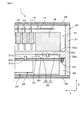
図2に示されるように、ケース30の平板状の仕切壁32と、コンバータ20の取り付け面を構成する平板状のベースプレート21とによって仕切部39が構成されている。この仕切部39によれば、ケース30の内部空間が、インバータ10を少なくとも収容する第1空間41と、コンバータ20を少なくとも収容する第2空間42とに区画される。これら第1空間41及び第2空間42はそれぞれがカバー38によって塞がれている。従って、仕切部39は、いずれもケース30に収容されたインバータ10とコンバータ20とを仕切るように構成されている。
As shown in FIG. 2, a
仕切部39は、仕切壁32の凹部がベースプレート21で塞がれることによって冷媒が流れる冷媒流路50を形成する。即ち、仕切部39において、仕切壁32及びベースプレート21は、冷媒流路50を挟んで第3方向Zの両側において互いに略平行となるように配置されている。仕切壁32を第1仕切壁とした場合、ベースプレート21が第2仕切壁になる。仕切部39は、これら仕切壁32及びベースプレート21の延在面に沿って延在している。仕切壁32の凹部をベースプレート21で塞ぐ構成によれば、冷媒流路50を有する仕切部39を比較的簡単に構築できる。
The partitioning
ベースプレート21は、ケース30と同様のアルミニウム材料からなる。ベースプレート21は、液状ガスケット、ゴム等のシール材(図示省略)を介して仕切壁32に当接した状態で締結ボルト23によってケース30に固定されている。これにより冷媒流路50の気密性が確保されている。冷媒流路50は、第3方向Zについての流路高さZaが概ね一定となるように構成されている。
The
仕切壁32は、受熱面32a及び放熱面32bを有する。受熱面32aは、インバータ10を収容する第1空間41に臨む面である。この受熱面32aには、インバータ10を構成する発熱部品であり、その他の部品に比べて発熱量が大きいリアクトル18(以下、「第1発熱部品18」ともいう。)が接合されている。即ち、第1発熱部品18は、仕切壁32の受熱面32aに接している。この受熱面32aは、第1発熱部品18に対する接合面として構成されている。放熱面32bは、仕切壁32の両面のうち受熱面32aとは反対側の面であり、仕切壁32の凹部の底面として構成されている。この放熱面32bは、冷媒流路50を区画しており、この冷媒流路50において冷媒流れ方向Dに流れる冷媒に常時に接触する。
The
ベースプレート21は、受熱面21a及び放熱面21bを有する。受熱面21aには、コンバータ20を構成する第2発熱部品24が接合されている。即ち、第2発熱部品24は、ベースプレート21の受熱面21aに接している。この受熱面21aは、第2発熱部品24に対する接合面として構成されている。第2発熱部品24には、その他の部品に比べて発熱量が大きいトランス25、チョークコイル26及びフィルタコンデンサ27が含まれている。トランス25は、直流電力を降圧する機能を有する。トランス25によって降圧された直流電力について、チョークコイル26においてリップル電流が除去され、且つフィルタコンデンサ27においてノイズ電圧が除去される。放熱面21bは、ベースプレート21の両面のうち受熱面21aとは反対側の面である。この放熱面21bは、冷媒流路50を区画しており、この冷媒流路50において冷媒流れ方向Dに流れる冷媒に常時に接触する。
The
第1発熱部品18と第2発熱部品24は、冷媒流路50における冷媒流れ方向Dと直交する第3方向Z(以下、「直交方向Z」ともいう。)について互いに重ならない位置において仕切部39にそれぞれ接合されている。換言すれば、第1発熱部品18と第2発熱部品24は、冷媒流れ方向Dについて互いにずれた位置において仕切部39にそれぞれ接合されている。或いは、第1発熱部品18と第2発熱部品24は、第3方向Zについて一方側から他方側を視たときに互いに重ならない位置において仕切部39にそれぞれ接合されている。この場合、直交方向Zは、仕切部39の接合面(仕切壁32の受熱面32a、及びベースプレート21の受熱面21a)に対する法線方向(直交方向)、或いは冷媒流路50に沿った仮想平面Pに対する法線方向(直交方向)としても定義される。
The first
図3に示されるように、冷媒供給管36は、接続管16aを介して前記の冷媒排出ヘッダ16に接続されている。本実施形態では、半導体モジュール11の冷却で使用した冷媒をそのまま冷媒流路50でも使用している。なお、必要に応じて、この冷媒流路50を半導体モジュール11の冷媒流路から切り離すこともできる。
As shown in FIG. 3, the
図3及び図4に示されるように、仕切壁32には、冷媒流路50を形成するために、放熱面32bのうち第2方向Yの中間位置からベースプレート21に向けて立設し且つ第1方向Xに長尺状に延在する立設部33が設けられている。これにより、冷媒流路50は、冷媒供給管36から流入した冷媒が立設部33を隔てた片側半分の領域を流れた後、U字状にターンして残りの半分の領域を流れて冷媒排出管37から外部に排出されるように構成されている。本構成では、Uターン箇所が1箇所である。立設部33は、その立設先端部33aがベースプレート21の放熱面21bに隙間なく当接している。この立設部33は、冷媒流路50の流路高さZaと同様の立設高さを有する。
As shown in FIG. 3 and FIG. 4, in order to form the
冷媒流路50は、上流から順に配置された、第1区間51、第2区間52、第3区間53及び第4区間54を含む流路として構成されている。第1区間51は、冷媒が第1方向Xの一方側に直線的に流れる区間である。第2区間52は、冷媒が第1方向Xの一方側から他方側へとUターンして流れる区間である。第3区間53及び第4区間54はいずれも、冷媒が第1区間51とは逆方向に直線的に流れる区間である。従って、冷媒流路50は、その流路の向きが変わるように構成されたターン流路である。これにより、流路の向きが変わることなく直線的に形成されている冷媒流路に比べて流路を延ばすことができ、冷媒の流速を高く設定できる。
The
仕切壁32は、冷媒流路50の第2区間52に対応した領域に複数(本実施形態では3つ)の第1放熱フィン34を備えている。第1放熱フィン34は、冷媒流路50に対向する放熱面32bのうち直交方向Zについて第1発熱部品18を通る位置、即ち第1発熱部品18の直下の位置から冷媒流路50に向けて延出している。また、この第1放熱フィン34は、その延出先端部34aがベースプレート21の放熱面21bに隙間なく当接している。この場合、第1放熱フィン34は、冷媒流路50の流路高さZaと同様の立設高さを有する。
The
第1放熱フィン34は、一様な板厚で冷媒流れ方向Dに沿って延びる湾曲板状であり、仕切壁32と冷媒との間の接触面積(放熱面32bのうち第1発熱部品18の直下からの放熱面積)を増やす機能を有する。また、第2区間52では、3つの第1放熱フィン34の板厚に相当する分の流路が絞られるため、この第1放熱フィン34は、冷媒の流速を高める機能を有する。これらの機能によれば、仕切壁32からの放熱量を増やすことができる。更に、この第1放熱フィン34は、冷媒流れ方向Dに沿って延びるため、冷媒が受ける流路抵抗を低く抑える機能を有する。この機能によれば、冷媒をその流れを整えつつ円滑に流すことができる。なお、この第1放熱フィン34の数は、1つであってもよいし複数であってもよい。
The first
仕切壁32は、冷媒流路50の第3区間53に対応した領域に複数(本実施形態では2つ)の整流フィン35を備えている。整流フィン35は、放熱面32bからベースプレート21に向けて延出し、且つその延出先端部35aがベースプレート21の放熱面21bに当接している。
The
整流フィン35は、冷媒流れを整えることによって冷媒流路50に空気溜りが形成されるのを防止するとともに、第1放熱フィン34と同様に冷媒との接触面積を増やす機能を有する。なお、この整流フィン35の数は、1つであってもよいし複数であってもよい。或いは、冷媒流れを整える要請が低い場合には、この整流フィン35を省略することもできる。
The straightening
図5及び図6に示されるように、仕切壁32は、冷媒流路50の第1区間51及び第4区間54に対応した領域に複数(本実施形態では2つ)の第2放熱フィン22を備えている。第2放熱フィン22は、冷媒流路50に対向する放熱面21bのうち直交方向Zについて第2発熱部品24を通る位置、即ち第2発熱部品24の直下の位置から冷媒流路50に向けて延出している。また、この第2放熱フィン22は、その延出先端部22aが仕切壁32の放熱面32bに隙間なく当接している。この場合、第2放熱フィン22は、第1放熱フィン34と同様に、冷媒流路50の流路高さZaと同様の立設高さを有する。このため、電力変換装置1の直交方向Zの寸法を小さく抑えることができる。
As shown in FIGS. 5 and 6, the
第2放熱フィン22は、一様な板厚で冷媒流れ方向Dに沿って延びる平板状であり、ベースプレート21と冷媒との間の接触面積(放熱面21bのうち第2発熱部品24の直下からの放熱面積)を増やす機能を有する。また、第1区間51及び第4区間54ではいずれも、2つの第2放熱フィン22の板厚に相当する分の流路が絞られるため、この第2放熱フィン22は、冷媒の流速を高める機能を有する。これらの機能によれば、ベースプレート21からの放熱量を増やすことができる。更に、この第2放熱フィン22は、冷媒流れ方向Dに沿って延びるため、冷媒が受ける流路抵抗を低く抑える機能を有する。この機能によれば、冷媒をその流れを整えつつ円滑に流すことができる。なお、この第2放熱フィン22の数は、1つであってもよいし複数であってもよい。
The
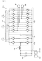
図7に示されるように、上記のインバータ10は、直流電源B1から供給される直流電力を交流電力に変換する電力変換回路であるインバータ回路10aを構成している。このインバータ回路10aにおいて、複数の半導体モジュール11は、制御回路基板17によってそのスイッチング動作(オンオフ動作)が制御される。
As shown in FIG. 7, the above-described
本実施形態では、リアクトル18及び2つの半導体モジュール11aによって、電力変換回路であるインバータ回路10aの昇圧部10bが構成されている。リアクトル18は、インダクタを利用した受動素子である。この昇圧部10bは、半導体モジュール11aのスイッチング動作(オンオフ動作)によって直流電源B1の電圧を昇圧する機能を有する。
In the present embodiment, the booster 18 b of the
一方で、コンデンサ19及び6つの半導体モジュール11bによって、電力変換回路であるインバータ回路10aの変換部10cが構成されている。この変換部10cは、昇圧部10bで昇圧された後の直流電力を半導体モジュール11bのスイッチング動作(オンオフ動作)によって交流電力に変換する機能を有する。変換部10cで得られた交流電力によって、車両走行用の三相交流モータMが駆動される。
On the other hand,
コンバータ20は、直流電源B1に接続されており、直流電源B1の電圧を降圧して、直流電源B1よりも低圧の補助バッテリB2を充電するのに用いられる。補助バッテリB2は、車両に搭載される各種機器の電源として使用される。
ここで、本実施形態の作用効果について説明する。
図8に示されるように、電力変換装置1の作動状態において、冷媒流路50を流れる冷媒によって仕切部39(仕切壁32及びベースプレート21)が冷却される。このため、この仕切部39に接する機器及び空気を冷却することができる。また、インバータ10とコンバータ20との間の電磁ノイズの干渉を防止できる。
Here, the operation and effect of the present embodiment will be described.
As shown in FIG. 8, in the operating state of the
以下、仕切部39に接する機器の冷却について具体的に説明する。インバータ10の第1発熱部品18で生じた熱は、熱伝導性の高い仕切壁32の受熱面32aにおいて受熱され放熱面32bから放熱される。そして、この放熱面32bから冷媒流路50の冷媒への熱移動によって、第1発熱部品18が連続的に冷却される。このとき、放熱面32bの中でも第1発熱部品18の直下である高温領域32cでの温度が相対的に高くなる。
Hereinafter, cooling of the device in contact with the
コンバータ20においてもこれと同様に、第2発熱部品24で生じた熱は、熱伝導性の高いベースプレート21の受熱面21aにおいて受熱され放熱面21bから放熱される。そして、この放熱面21bから冷媒流路50の冷媒への熱移動によって、第2発熱部品24が連続的に冷却される。このとき、放熱面21bの中でも第2発熱部品24の直下である高温領域21cでの温度が相対的に高くなる。従って、仕切壁32の高温領域32c及びベースプレート21の高温領域21cにおいては、特に高温の熱が冷媒に流入しようとする。
Similarly to this, also in the
このような状態において、仮に第1発熱部品18と第2発熱部品24が直交方向Zについて互いに重なるように配置されている場合、一定容量の冷媒に対して直交方向Zの両側から、即ち高温領域32c及び高温領域21cの双方から同時に熱が集中して流入しようする。ところが、一定容量の冷媒に一度に流入できる熱流入量には限りがあるため、高温領域32c及び高温領域21cのそれぞれの熱を同時に冷媒に円滑に流入させるのが難しい。即ち、一方の発熱部品で生じた熱と冷媒との間での熱交換が他方の発熱部品で生じた熱の影響を受け易い。
In such a state, if the first
そこで、本実施形態では、第1発熱部品18と第2発熱部品24が直交方向Zについて互いに重ならないようにしている。換言すれば、第1発熱部品18の直下の高温領域32cと、第2発熱部品24の直下の高温領域21cとが、冷媒流れ方向Dについて互いに離間するように構成されている。この場合、第1発熱部品18を通る直交方向Zの仮想線Lは、第2発熱部品24から外れた位置を通る。
Therefore, in the present embodiment, the first
本構成によれば、一定容量の冷媒に対して高温領域32c及び高温領域21cの双方から同時に熱が集中して流入するのを回避できる。即ち、一定容量の冷媒に対して直交方向Zの両側から同時に熱が流入することを抑制できる。例えば、冷媒が冷媒流路50を図8中の冷媒流れ方向D1に流れている場合、上流側の高温領域21cと下流側の高温領域32cとでは互いの熱干渉を生じにくい。その結果、第1発熱部品18を含むインバータ10と第2発熱部品24を含むコンバータ20との双方の冷却性能が向上する。
According to this configuration, it is possible to prevent heat from being concentrated and flowing simultaneously from both the
以上のごとく、本実施形態によれば、2つの電力変換器10,20のそれぞれの発熱部品18,24を直交方向Zについて互いに重ならないように位置をずらして仕切部39に接合することによって、2つの電力変換器10,20の冷却性能を向上させることができる。
As described above, according to the present embodiment, the
また、第1放熱フィン34及び第2放熱フィン22によって放熱性能を高め且つ冷媒の流速を高めるとともに、冷媒流路50をターン流路として冷媒の流速を高めることによって、2つの電力変換器10,20の冷却性能を更に向上させることができる。
The two
本発明は、上記の典型的な実施形態のみに限定されるものではなく、本発明の目的を逸脱しない限りにおいて種々の応用や変形が考えられる。例えば、上記の実施形態を応用した次の各形態を実施することもできる。 The invention is not limited to the exemplary embodiments described above, but various applications and modifications are conceivable without departing from the object of the invention. For example, the following embodiments to which the above embodiment is applied can be implemented.
上記の実施形態では、図2に示される電力変換装置1のように、ケース30の仕切壁32と、ケース30とは別部材であるベースプレート21とによって仕切部39が構成される場合について例示したが、仕切部39は1または複数の要素によって構成され得る。例えば、図9に示される電力変換装置101のように、ケース30の仕切壁32自体によって仕切部39が構成されてもよい。この電力変換装置101は、ベースプレート21が省略されている点について、電力変換装置1と相違している。仕切部39としての仕切壁32は、受熱面32a及び放熱面32bに加えて、受熱面32d及び放熱面32eを有する。受熱面32dには、第2発熱部品24が接合されている。放熱面32eは、冷媒流路50を区画しており、冷媒流路50を流れる冷媒に常時に接触する。これにより、電力変換装置101の部品点数を減らすことができる。
この電力変換装置101は、その他については電力変換装置1と同様の構成および作用効果を有する。
In the above embodiment, as in the
The
上記の実施形態では、冷却性能を高めるために仕切壁32に第1放熱フィン34を設け、且つベースプレート21に第2放熱フィン22を設ける場合について例示したが、これら第1放熱フィン34及び第2放熱フィン22のうちの少なくとも一方を省略することもできる。第1放熱フィン34及び第2放熱フィン22の双方が省略された別実施形態については図10及び図11が参照される。なお、これらの図面において、図3及び図5に示される要素と同一の要素には同一の符号を付しており、該同一の要素についての説明は省略する。
In the above embodiment, the first
仕切部39は、図10に示されるケース130の仕切壁132と、図11示されるベースプレート121とによって構成される。仕切壁132においては、立設部33の第2方向Yの位置が図3の場合に比べて変更されることによって、冷媒流路50の上流側領域50aの流路断面積が下流側領域50bの流路断面積よりも小さくなるように構成されている。これにより、冷媒流路50における冷媒の流速は、上流側領域50aの方が下流側領域50bよりも高くなる。そして、仕切壁32の受熱面32aのうち直交方向Zについて上流側領域50aを通る位置に第1発熱部品18が接合されている。一方で、ベースプレート121の受熱面32aのうち直交方向Zについて上流側領域50aを通る位置に第2発熱部品24が接合されている。換言すれば、仕切部39は、冷媒流路50のうち直交方向Zについて第1発熱部品18及び第2発熱部品24のそれぞれと重なる領域での冷媒の流速が相対的に高くなるように構成されている。本構成によれば、放熱フィンを用いることなく冷媒の流速を高めることができる。
The
上記の実施形態では、第1放熱フィン34及び第2放熱フィン22がいずれも冷媒流路50の流路高さZaと同様の立設高さを有する場合について例示したが、第1放熱フィン34及び第2放熱フィン22のうちの少なくとも一方の立設高さが冷媒流路50の流路高さZaを下回る構成を採用することもできる。
In the above embodiment, although the first
上記の実施形態では、冷媒流路50におけるUターン箇所が1箇所である場合について例示したが、必要に応じてUターン箇所が2箇所以上であってもよい。また、冷媒流路50におけるターン流路の形状はU字状以外、例えばL字状であってもよい。また、冷媒流路50は、その流路の向きが殆ど変わることなく直線的に延びるように構成されてもよい。
In the above embodiment, the case where the number of U-turns in the
上記の実施形態では、第1発熱部品18としてインバータ10のリアクトル18を例示し、第2発熱部品24としてコンバータ20のトランス25、チョークコイル26及びフィルタコンデンサ27を例示したが、第1発熱部品18及び第2発熱部品24のそれぞれは必要に応じて種々変更可能である。例えば、第1発熱部品18として、コンデンサ19や、直流電源B1から供給される電流に含まれるノイズ電流を除去するフィルタコンデンサ等を採用することもできる。
In the above embodiment, the
上記の実施形態では、ベースプレート21,121及びケース30,130がともにアルミニウム材料からなる場合について例示したが、アルミニウム材料に代えて、他の金属材料や熱伝導性の高い金属材料以外の材料を用いることもできる。
In the above embodiment, the case where the
1,101 電力変換装置
10 第1電力変換器(インバータ)
18 リアクトル(第1発熱部品)
20 第2電力変換器(コンバータ)
21,121 ベースプレート(第2仕切壁)
22 第2放熱フィン
22a 延出先端部
24 第2発熱部品
30,130 ケース
32,132 仕切壁(第1仕切壁)
32b 放熱面
34 第1放熱フィン
34a 延出先端部
39 仕切部
50 冷媒流路
D 冷媒流れ方向
Z 直交方向(第3方向)
1,101
18 reactor (1st heat generating component)
20 Second power converter (converter)
21, 121 Base plate (second partition wall)
22 second
32b
Claims (7)
上記第1電力変換器及び上記第2電力変換器を収容するケース(30)と、
上記ケースに収容された上記第1電力変換器と上記第2電力変換器とを仕切るとともに冷媒が流れる冷媒流路(50)を形成する仕切部(39)と、
を含み、
上記第1電力変換器を構成する第1発熱部品(18)と上記第2電力変換器を構成する第2発熱部品(24)は、上記冷媒流路における冷媒流れ方向(D)と直交する直交方向(Z)について互いに重ならない位置において上記仕切部に直に接しており、
上記第1発熱部品が上記直交方向について上記仕切部側に投影された範囲内において、上記仕切部と熱的に接する発熱部品が上記第1発熱部品のみである、電力変換装置(1)。 A first power converter (10) and a second power converter (20) each performing power conversion;
A case (30) accommodating the first power converter and the second power converter;
A partition (39) for partitioning the first power converter and the second power converter housed in the case and forming a refrigerant flow path (50) through which the refrigerant flows;
Including
The first heat generating component (18) constituting the first power converter and the second heat generating component (24) constituting the second power converter are orthogonal to the refrigerant flow direction (D) in the refrigerant channel. Directly in contact with the partition at a position not overlapping each other in the direction (Z) ,
The power conversion device (1), wherein the only heat generating component in thermal contact with the partition is the first heat generating component within a range where the first heat generating component is projected on the side of the partition in the orthogonal direction .
上記仕切部は、上記冷媒流路に対向する放熱面(32b)のうち上記第1発熱部品が上記直交方向について上記仕切部側に投影された範囲内で上記冷媒流路に向けて延出する第1放熱フィン(34)を備え、上記第1放熱フィンが上記ターン流路に沿って設けられている、請求項1に記載の電力変換装置。The partition portion extends toward the coolant channel within a range in which the first heat-generating component of the heat release surface (32b) facing the coolant channel is projected on the partition side in the orthogonal direction. The power converter according to claim 1, further comprising a first radiation fin (34), wherein the first radiation fin is provided along the turn flow path.
Priority Applications (3)
| Application Number | Priority Date | Filing Date | Title |
|---|---|---|---|
| JP2015246440A JP6540496B2 (en) | 2015-12-17 | 2015-12-17 | Power converter |
| CN201611166134.6A CN106899215B (en) | 2015-12-17 | 2016-12-16 | Power conversion device |
| US15/382,802 US9986665B2 (en) | 2015-12-17 | 2016-12-19 | Power conversion apparatus |
Applications Claiming Priority (1)
| Application Number | Priority Date | Filing Date | Title |
|---|---|---|---|
| JP2015246440A JP6540496B2 (en) | 2015-12-17 | 2015-12-17 | Power converter |
Related Child Applications (1)
| Application Number | Title | Priority Date | Filing Date |
|---|---|---|---|
| JP2019108688A Division JP6809563B2 (en) | 2019-06-11 | 2019-06-11 | Power converter |
Publications (2)
| Publication Number | Publication Date |
|---|---|
| JP2017112768A JP2017112768A (en) | 2017-06-22 |
| JP6540496B2 true JP6540496B2 (en) | 2019-07-10 |
Family
ID=59066975
Family Applications (1)
| Application Number | Title | Priority Date | Filing Date |
|---|---|---|---|
| JP2015246440A Active JP6540496B2 (en) | 2015-12-17 | 2015-12-17 | Power converter |
Country Status (3)
| Country | Link |
|---|---|
| US (1) | US9986665B2 (en) |
| JP (1) | JP6540496B2 (en) |
| CN (1) | CN106899215B (en) |
Families Citing this family (31)
| Publication number | Priority date | Publication date | Assignee | Title |
|---|---|---|---|---|
| EP2802198B1 (en) * | 2013-05-08 | 2017-07-26 | Kabushiki Kaisha Toshiba | Power conversion apparatus |
| JP6278243B2 (en) * | 2015-01-07 | 2018-02-14 | 株式会社オートネットワーク技術研究所 | Power storage unit |
| KR20180016102A (en) * | 2016-08-05 | 2018-02-14 | 엘지이노텍 주식회사 | Electronic component package |
| CN108347863A (en) * | 2017-01-25 | 2018-07-31 | 全汉企业股份有限公司 | Power supply device |
| JP6862271B2 (en) * | 2017-05-15 | 2021-04-21 | 株式会社Soken | Power converter |
| JP6758264B2 (en) * | 2017-08-10 | 2020-09-23 | 株式会社デンソー | Reactor cooling structure |
| US10483028B2 (en) * | 2017-12-18 | 2019-11-19 | Deere & Company | Electrical assembly having cavities for coolant |
| KR102542936B1 (en) * | 2018-02-09 | 2023-06-14 | 현대자동차주식회사 | Cooling structure of power converting apparatus |
| JP7087452B2 (en) * | 2018-03-02 | 2022-06-21 | 株式会社デンソー | Power converter |
| US10141862B1 (en) * | 2018-03-20 | 2018-11-27 | Ford Global Technologies, Llc | Power supply device |
| JP6943212B2 (en) * | 2018-03-28 | 2021-09-29 | トヨタ自動車株式会社 | Power converter |
| CN111903046A (en) * | 2018-03-30 | 2020-11-06 | 日本电产株式会社 | Power conversion device |
| CN108667216A (en) * | 2018-04-28 | 2018-10-16 | 合肥巨动力系统有限公司 | A kind of channel structure that controller is connect with motor |
| CN108401405B (en) * | 2018-04-28 | 2019-09-27 | 合肥巨一动力系统有限公司 | Water-cooled motor controller |
| JP6992670B2 (en) * | 2018-05-09 | 2022-01-13 | 株式会社デンソー | Power controller |
| JP7024592B2 (en) * | 2018-05-11 | 2022-02-24 | 株式会社デンソー | Power converter |
| DE102018111619A1 (en) * | 2018-05-15 | 2019-11-21 | Valeo Siemens Eautomotive Germany Gmbh | Housing for an inverter with cooling system for an electric drive |
| US11881791B2 (en) * | 2018-07-04 | 2024-01-23 | Hitachi Astemo, Ltd. | Electromagnetic shielding power conversion device |
| CN109361240A (en) * | 2018-12-10 | 2019-02-19 | 阳光电源股份有限公司 | Power cabinet, photovoltaic parallel in system and container |
| JP7263766B2 (en) | 2018-12-27 | 2023-04-25 | 株式会社デンソー | power converter |
| JP7147565B2 (en) * | 2019-01-08 | 2022-10-05 | 株式会社デンソー | power conversion unit |
| EP3684154B1 (en) * | 2019-01-21 | 2024-03-06 | Aptiv Technologies Limited | Thermally conductive insert element for electronic unit |
| JP6827571B1 (en) * | 2020-01-08 | 2021-02-10 | 三菱電機株式会社 | Power converter |
| JP6806276B1 (en) * | 2020-03-05 | 2021-01-06 | 富士電機株式会社 | Power converter |
| DE102020109726A1 (en) | 2020-04-07 | 2021-10-07 | Semikron Elektronik Gmbh & Co. Kg | Power electronic system with a total cooling device and a plurality of partial cooling devices |
| JP7420051B2 (en) | 2020-11-03 | 2024-01-23 | 株式会社デンソー | power converter |
| KR20220089348A (en) * | 2020-12-21 | 2022-06-28 | 현대자동차주식회사 | Apparatus of driving motor |
| US11825635B2 (en) * | 2021-08-16 | 2023-11-21 | Quanta Computer Inc. | Immersion liquid cooling system |
| WO2023136800A1 (en) * | 2022-01-14 | 2023-07-20 | Aselsan Elektroni̇k Sanayi̇ Ve Ti̇caret Anoni̇m Şi̇rketi̇ | A two-layer cooling system |
| DE102022200734A1 (en) * | 2022-01-24 | 2023-07-27 | Robert Bosch Gesellschaft mit beschränkter Haftung | Heat sink for cooling electronic components and arrangement with a heat sink |
| JP7435876B2 (en) | 2022-04-22 | 2024-02-21 | 富士電機株式会社 | Trance |
Family Cites Families (20)
| Publication number | Priority date | Publication date | Assignee | Title |
|---|---|---|---|---|
| JPH07194139A (en) * | 1993-12-27 | 1995-07-28 | Hitachi Ltd | Cooling device of inverter for electric automobile |
| FR2861894B1 (en) * | 2003-10-31 | 2008-01-18 | Valeo Equip Electr Moteur | DEVICE FOR COOLING A POWER ELECTRONIC |
| JPWO2005071824A1 (en) * | 2004-01-26 | 2007-08-23 | 株式会社日立製作所 | Semiconductor device |
| JP2005332863A (en) * | 2004-05-18 | 2005-12-02 | Denso Corp | Power stack |
| JP4284625B2 (en) * | 2005-06-22 | 2009-06-24 | 株式会社デンソー | Three-phase inverter device |
| US7764041B2 (en) * | 2007-01-22 | 2010-07-27 | Johnson Controls Technology Company | System and method to extend synchronous operation of an active converter in a variable speed drive |
| JP4827770B2 (en) * | 2007-03-05 | 2011-11-30 | 株式会社小松製作所 | Cooling casing and inverter device using the cooling casing |
| JP4274271B2 (en) * | 2007-07-26 | 2009-06-03 | トヨタ自動車株式会社 | Voltage converter |
| JP4819071B2 (en) * | 2008-02-06 | 2011-11-16 | 本田技研工業株式会社 | Electric vehicle and cooling method for DC / DC converter for vehicle |
| JP4580997B2 (en) * | 2008-03-11 | 2010-11-17 | 日立オートモティブシステムズ株式会社 | Power converter |
| JP2010103235A (en) * | 2008-10-22 | 2010-05-06 | Calsonic Kansei Corp | Heat exchanger |
| US8325479B2 (en) * | 2010-07-16 | 2012-12-04 | Rockwell Automation Technologies, Inc. | Motor drive cooling duct system and method |
| JP5236838B2 (en) * | 2010-10-27 | 2013-07-17 | 本田技研工業株式会社 | Cooling structure |
| JP5488565B2 (en) * | 2011-03-29 | 2014-05-14 | 株式会社デンソー | Power converter |
| JP6213974B2 (en) * | 2012-07-26 | 2017-10-18 | 住友重機械工業株式会社 | Work machine |
| JP6085196B2 (en) * | 2013-03-11 | 2017-02-22 | 株式会社フジクラ | Double-sided mounting cooling plate |
| JP5971403B2 (en) * | 2013-03-19 | 2016-08-17 | 富士電機株式会社 | Cooling device and power conversion device provided with the same |
| JP6089996B2 (en) * | 2013-06-19 | 2017-03-08 | 株式会社デンソー | Power converter |
| EP2825009B8 (en) * | 2013-07-09 | 2016-11-23 | ABB Schweiz AG | Electric converter with compact module arrangement for subsea applications |
| JP6191371B2 (en) | 2013-10-04 | 2017-09-06 | 株式会社デンソー | Power converter |
-
2015
- 2015-12-17 JP JP2015246440A patent/JP6540496B2/en active Active
-
2016
- 2016-12-16 CN CN201611166134.6A patent/CN106899215B/en active Active
- 2016-12-19 US US15/382,802 patent/US9986665B2/en active Active
Also Published As
| Publication number | Publication date |
|---|---|
| JP2017112768A (en) | 2017-06-22 |
| US20170181333A1 (en) | 2017-06-22 |
| CN106899215B (en) | 2020-06-05 |
| US9986665B2 (en) | 2018-05-29 |
| CN106899215A (en) | 2017-06-27 |
Similar Documents
| Publication | Publication Date | Title |
|---|---|---|
| JP6540496B2 (en) | Power converter | |
| JP5855899B2 (en) | DC-DC converter and power converter | |
| JP5504219B2 (en) | Power converter | |
| JP6631431B2 (en) | Power converter | |
| US10847441B2 (en) | Cooling system | |
| JP2017152612A (en) | Electric power conversion system | |
| JP2007173372A (en) | Power converter | |
| WO2019031596A1 (en) | Reactor cooling structure | |
| JP2015042131A (en) | Electric power conversion system | |
| EP3641121A1 (en) | Cooling structure of power conversion device | |
| JP6971821B2 (en) | Power converter | |
| JP5712750B2 (en) | Power converter | |
| JP6115430B2 (en) | Power converter | |
| JP6809563B2 (en) | Power converter | |
| JP2016163478A (en) | Power converter | |
| JP7139603B2 (en) | power converter | |
| JP7379958B2 (en) | power converter | |
| JP7276085B2 (en) | power converter | |
| WO2019244624A1 (en) | Electric power converter | |
| WO2019159666A1 (en) | Electronic component with cooler, and inverter | |
| JP7443859B2 (en) | power converter | |
| JP7318765B2 (en) | power converter | |
| US20230232599A1 (en) | Cooler and semiconductor apparatus | |
| JP6512125B2 (en) | Power converter | |
| JP2022019040A (en) | Electric power conversion device |
Legal Events
| Date | Code | Title | Description |
|---|---|---|---|
| A621 | Written request for application examination |
Free format text: JAPANESE INTERMEDIATE CODE: A621 Effective date: 20180412 |
|
| A977 | Report on retrieval |
Free format text: JAPANESE INTERMEDIATE CODE: A971007 Effective date: 20190208 |
|
| A131 | Notification of reasons for refusal |
Free format text: JAPANESE INTERMEDIATE CODE: A131 Effective date: 20190219 |
|
| A521 | Request for written amendment filed |
Free format text: JAPANESE INTERMEDIATE CODE: A523 Effective date: 20190416 |
|
| TRDD | Decision of grant or rejection written | ||
| A01 | Written decision to grant a patent or to grant a registration (utility model) |
Free format text: JAPANESE INTERMEDIATE CODE: A01 Effective date: 20190514 |
|
| A61 | First payment of annual fees (during grant procedure) |
Free format text: JAPANESE INTERMEDIATE CODE: A61 Effective date: 20190527 |
|
| R151 | Written notification of patent or utility model registration |
Ref document number: 6540496 Country of ref document: JP Free format text: JAPANESE INTERMEDIATE CODE: R151 |
|
| R250 | Receipt of annual fees |
Free format text: JAPANESE INTERMEDIATE CODE: R250 |
|
| R250 | Receipt of annual fees |
Free format text: JAPANESE INTERMEDIATE CODE: R250 |