WO2019031596A1 - Reactor cooling structure - Google Patents
Reactor cooling structure Download PDFInfo
- Publication number
- WO2019031596A1 WO2019031596A1 PCT/JP2018/030007 JP2018030007W WO2019031596A1 WO 2019031596 A1 WO2019031596 A1 WO 2019031596A1 JP 2018030007 W JP2018030007 W JP 2018030007W WO 2019031596 A1 WO2019031596 A1 WO 2019031596A1
- Authority
- WO
- WIPO (PCT)
- Prior art keywords
- reactor
- reactors
- cooling structure
- exterior
- structure according
- Prior art date
Links
Images


Classifications
-
- H—ELECTRICITY
- H01—ELECTRIC ELEMENTS
- H01F—MAGNETS; INDUCTANCES; TRANSFORMERS; SELECTION OF MATERIALS FOR THEIR MAGNETIC PROPERTIES
- H01F27/00—Details of transformers or inductances, in general
- H01F27/08—Cooling; Ventilating
- H01F27/10—Liquid cooling
-
- H—ELECTRICITY
- H02—GENERATION; CONVERSION OR DISTRIBUTION OF ELECTRIC POWER
- H02M—APPARATUS FOR CONVERSION BETWEEN AC AND AC, BETWEEN AC AND DC, OR BETWEEN DC AND DC, AND FOR USE WITH MAINS OR SIMILAR POWER SUPPLY SYSTEMS; CONVERSION OF DC OR AC INPUT POWER INTO SURGE OUTPUT POWER; CONTROL OR REGULATION THEREOF
- H02M3/00—Conversion of dc power input into dc power output
- H02M3/02—Conversion of dc power input into dc power output without intermediate conversion into ac
- H02M3/04—Conversion of dc power input into dc power output without intermediate conversion into ac by static converters
- H02M3/10—Conversion of dc power input into dc power output without intermediate conversion into ac by static converters using discharge tubes with control electrode or semiconductor devices with control electrode
- H02M3/145—Conversion of dc power input into dc power output without intermediate conversion into ac by static converters using discharge tubes with control electrode or semiconductor devices with control electrode using devices of a triode or transistor type requiring continuous application of a control signal
- H02M3/155—Conversion of dc power input into dc power output without intermediate conversion into ac by static converters using discharge tubes with control electrode or semiconductor devices with control electrode using devices of a triode or transistor type requiring continuous application of a control signal using semiconductor devices only
- H02M3/156—Conversion of dc power input into dc power output without intermediate conversion into ac by static converters using discharge tubes with control electrode or semiconductor devices with control electrode using devices of a triode or transistor type requiring continuous application of a control signal using semiconductor devices only with automatic control of output voltage or current, e.g. switching regulators
- H02M3/158—Conversion of dc power input into dc power output without intermediate conversion into ac by static converters using discharge tubes with control electrode or semiconductor devices with control electrode using devices of a triode or transistor type requiring continuous application of a control signal using semiconductor devices only with automatic control of output voltage or current, e.g. switching regulators including plural semiconductor devices as final control devices for a single load
- H02M3/1584—Conversion of dc power input into dc power output without intermediate conversion into ac by static converters using discharge tubes with control electrode or semiconductor devices with control electrode using devices of a triode or transistor type requiring continuous application of a control signal using semiconductor devices only with automatic control of output voltage or current, e.g. switching regulators including plural semiconductor devices as final control devices for a single load with a plurality of power processing stages connected in parallel
-
- H—ELECTRICITY
- H01—ELECTRIC ELEMENTS
- H01F—MAGNETS; INDUCTANCES; TRANSFORMERS; SELECTION OF MATERIALS FOR THEIR MAGNETIC PROPERTIES
- H01F27/00—Details of transformers or inductances, in general
- H01F27/06—Mounting, supporting or suspending transformers, reactors or choke coils not being of the signal type
-
- H—ELECTRICITY
- H01—ELECTRIC ELEMENTS
- H01F—MAGNETS; INDUCTANCES; TRANSFORMERS; SELECTION OF MATERIALS FOR THEIR MAGNETIC PROPERTIES
- H01F27/00—Details of transformers or inductances, in general
- H01F27/08—Cooling; Ventilating
- H01F27/10—Liquid cooling
- H01F27/105—Cooling by special liquid or by liquid of particular composition
-
- H—ELECTRICITY
- H01—ELECTRIC ELEMENTS
- H01F—MAGNETS; INDUCTANCES; TRANSFORMERS; SELECTION OF MATERIALS FOR THEIR MAGNETIC PROPERTIES
- H01F27/00—Details of transformers or inductances, in general
- H01F27/08—Cooling; Ventilating
- H01F27/10—Liquid cooling
- H01F27/16—Water cooling
-
- H—ELECTRICITY
- H01—ELECTRIC ELEMENTS
- H01F—MAGNETS; INDUCTANCES; TRANSFORMERS; SELECTION OF MATERIALS FOR THEIR MAGNETIC PROPERTIES
- H01F27/00—Details of transformers or inductances, in general
- H01F27/24—Magnetic cores
- H01F27/255—Magnetic cores made from particles
-
- H—ELECTRICITY
- H01—ELECTRIC ELEMENTS
- H01F—MAGNETS; INDUCTANCES; TRANSFORMERS; SELECTION OF MATERIALS FOR THEIR MAGNETIC PROPERTIES
- H01F37/00—Fixed inductances not covered by group H01F17/00
-
- H—ELECTRICITY
- H02—GENERATION; CONVERSION OR DISTRIBUTION OF ELECTRIC POWER
- H02M—APPARATUS FOR CONVERSION BETWEEN AC AND AC, BETWEEN AC AND DC, OR BETWEEN DC AND DC, AND FOR USE WITH MAINS OR SIMILAR POWER SUPPLY SYSTEMS; CONVERSION OF DC OR AC INPUT POWER INTO SURGE OUTPUT POWER; CONTROL OR REGULATION THEREOF
- H02M7/00—Conversion of ac power input into dc power output; Conversion of dc power input into ac power output
- H02M7/003—Constructional details, e.g. physical layout, assembly, wiring or busbar connections
-
- H—ELECTRICITY
- H02—GENERATION; CONVERSION OR DISTRIBUTION OF ELECTRIC POWER
- H02M—APPARATUS FOR CONVERSION BETWEEN AC AND AC, BETWEEN AC AND DC, OR BETWEEN DC AND DC, AND FOR USE WITH MAINS OR SIMILAR POWER SUPPLY SYSTEMS; CONVERSION OF DC OR AC INPUT POWER INTO SURGE OUTPUT POWER; CONTROL OR REGULATION THEREOF
- H02M7/00—Conversion of ac power input into dc power output; Conversion of dc power input into ac power output
- H02M7/42—Conversion of dc power input into ac power output without possibility of reversal
- H02M7/44—Conversion of dc power input into ac power output without possibility of reversal by static converters
- H02M7/48—Conversion of dc power input into ac power output without possibility of reversal by static converters using discharge tubes with control electrode or semiconductor devices with control electrode
- H02M7/53—Conversion of dc power input into ac power output without possibility of reversal by static converters using discharge tubes with control electrode or semiconductor devices with control electrode using devices of a triode or transistor type requiring continuous application of a control signal
- H02M7/537—Conversion of dc power input into ac power output without possibility of reversal by static converters using discharge tubes with control electrode or semiconductor devices with control electrode using devices of a triode or transistor type requiring continuous application of a control signal using semiconductor devices only, e.g. single switched pulse inverters
- H02M7/5387—Conversion of dc power input into ac power output without possibility of reversal by static converters using discharge tubes with control electrode or semiconductor devices with control electrode using devices of a triode or transistor type requiring continuous application of a control signal using semiconductor devices only, e.g. single switched pulse inverters in a bridge configuration
- H02M7/53871—Conversion of dc power input into ac power output without possibility of reversal by static converters using discharge tubes with control electrode or semiconductor devices with control electrode using devices of a triode or transistor type requiring continuous application of a control signal using semiconductor devices only, e.g. single switched pulse inverters in a bridge configuration with automatic control of output voltage or current
-
- H—ELECTRICITY
- H02—GENERATION; CONVERSION OR DISTRIBUTION OF ELECTRIC POWER
- H02M—APPARATUS FOR CONVERSION BETWEEN AC AND AC, BETWEEN AC AND DC, OR BETWEEN DC AND DC, AND FOR USE WITH MAINS OR SIMILAR POWER SUPPLY SYSTEMS; CONVERSION OF DC OR AC INPUT POWER INTO SURGE OUTPUT POWER; CONTROL OR REGULATION THEREOF
- H02M1/00—Details of apparatus for conversion
- H02M1/0067—Converter structures employing plural converter units, other than for parallel operation of the units on a single load
- H02M1/007—Plural converter units in cascade
-
- H—ELECTRICITY
- H02—GENERATION; CONVERSION OR DISTRIBUTION OF ELECTRIC POWER
- H02M—APPARATUS FOR CONVERSION BETWEEN AC AND AC, BETWEEN AC AND DC, OR BETWEEN DC AND DC, AND FOR USE WITH MAINS OR SIMILAR POWER SUPPLY SYSTEMS; CONVERSION OF DC OR AC INPUT POWER INTO SURGE OUTPUT POWER; CONTROL OR REGULATION THEREOF
- H02M1/00—Details of apparatus for conversion
- H02M1/0067—Converter structures employing plural converter units, other than for parallel operation of the units on a single load
- H02M1/008—Plural converter units for generating at two or more independent and non-parallel outputs, e.g. systems with plural point of load switching regulators
-
- H—ELECTRICITY
- H02—GENERATION; CONVERSION OR DISTRIBUTION OF ELECTRIC POWER
- H02M—APPARATUS FOR CONVERSION BETWEEN AC AND AC, BETWEEN AC AND DC, OR BETWEEN DC AND DC, AND FOR USE WITH MAINS OR SIMILAR POWER SUPPLY SYSTEMS; CONVERSION OF DC OR AC INPUT POWER INTO SURGE OUTPUT POWER; CONTROL OR REGULATION THEREOF
- H02M1/00—Details of apparatus for conversion
- H02M1/32—Means for protecting converters other than automatic disconnection
- H02M1/327—Means for protecting converters other than automatic disconnection against abnormal temperatures
-
- H—ELECTRICITY
- H02—GENERATION; CONVERSION OR DISTRIBUTION OF ELECTRIC POWER
- H02M—APPARATUS FOR CONVERSION BETWEEN AC AND AC, BETWEEN AC AND DC, OR BETWEEN DC AND DC, AND FOR USE WITH MAINS OR SIMILAR POWER SUPPLY SYSTEMS; CONVERSION OF DC OR AC INPUT POWER INTO SURGE OUTPUT POWER; CONTROL OR REGULATION THEREOF
- H02M3/00—Conversion of dc power input into dc power output
- H02M3/003—Constructional details, e.g. physical layout, assembly, wiring or busbar connections
Definitions
- the present disclosure relates to a structure for cooling a reactor.
- Patent Document 1 discloses a power converter provided with a plurality of reactors.
- a plurality of reactors are stacked one on another, and radiators made of a material having high thermal conductivity are disposed on both sides in the stacking direction.
- the heat generated in each of the plurality of reactors is dissipated to the outside from both sides of each of the reactors via the radiator.
- a refrigerant flow path through which the refrigerant flows is provided to the radiator.
- the present disclosure is intended to provide a reactor cooling structure that is high in performance of cooling a reactor and effective in achieving miniaturization.
- a plurality of reactors (11) which have a coil (17) which generates magnetic flux by energization in any case, and were laminated mutually,
- a cooling unit (20) for cooling the plurality of reactors; Equipped with The exterior portion (12) of each of the plurality of reactors has a heat dissipation surface (13) for heat dissipation of the coil on both sides in the stacking direction (X) of the plurality of reactors,
- a reactor cooling structure (10, 110, 210) having a cooling flow path (24) for directly cooling the heat dissipation surface of the exterior portion with a refrigerant (W); It is in.
- the heat dissipation surface of the exterior of each reactor is directly cooled by the refrigerant.
- the refrigerant flowing through the cooling flow passage of the cooling unit is in direct contact with the heat dissipation surface of the exterior portion. That is, another member does not intervene between the heat dissipation surface of the exterior portion and the refrigerant flowing through the cooling flow channel. For this reason, the performance which cools a reactor can be improved compared with the structure where another member intervenes between the heat dissipation side of an exterior part, and a refrigerant. It is also unnecessary to pressurize the exterior of the reactor and press it to the cooling unit in order to enhance this performance. In addition, the dimension in the stacking direction can be reduced by the amount that another member does not intervene between the heat dissipation surface of the exterior portion and the refrigerant.
- FIG. 1 is a plan view schematically showing a power conversion device according to a first embodiment
- FIG. 2 is a view of the semiconductor lamination unit in FIG. 1 as viewed from the lamination direction of the semiconductor modules
- FIG. 3 is an inverter circuit diagram of the power conversion device of FIG.
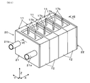
- FIG. 4 is a perspective view of the reactor cooling structure of the first embodiment
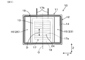
- FIG. 5 is a view of the reactor in FIG. 4 viewed from the stacking direction
- 6 is a partial exploded perspective view of the reactor cooling structure of FIG. 4
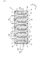
- 7 is a cross-sectional view taken along line VII-VII in FIG.
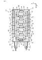
- FIG. 4; 8 is a sectional view taken along line VIII-VIII in FIG. 7;
- FIG. 9 is a partial cross-sectional view of a reactor cooling structure of Embodiment 2;
- FIG. 10 is a perspective view of a reactor of the reactor cooling structure of the third embodiment.
- a first direction which is a stacking direction of a plurality of reactors is indicated by an arrow X
- a stacking direction of a plurality of semiconductor modules constituting a power conversion device with a plurality of reactors is indicated by an arrow Y
- a third direction orthogonal to both the first direction X and the second direction Y is indicated by an arrow Z.
- the power conversion device 1 As shown in FIG. 1, the power conversion device 1 according to the first embodiment includes electronic components including a semiconductor multilayer unit 2, a plurality of reactors 11, a capacitor 6 and a converter 7 (see FIG. 3) in a case 1 a. And a control circuit board 8.
- the power conversion device 1 is mounted, for example, on an electric car, a hybrid car, etc., and is used as an inverter for converting direct current source power into alternating current power necessary for driving a driving motor.
- the semiconductor lamination unit 2 includes a plurality of semiconductor modules 3 and a cooler 5 having a plurality of cooling pipes 5a through which the refrigerant flows.
- a plurality of semiconductor modules 3 and a plurality (9 in FIG. 1) of cooling pipes 5a are alternately laminated in the second direction Y. That is, each semiconductor module 3 is held by the two cooling pipes 5a from both side surfaces in the second direction Y.
- the semiconductor module 3 incorporates a semiconductor element 4 such as an IGBT that converts direct current power into alternating current power.
- the semiconductor module 3 is provided with a plurality of control terminals 4 a electrically connected to the control circuit board 8 and a power terminal 4 b for power supply.
- the control circuit board 8 is configured to control the switching operation of the semiconductor element 4 in order to convert direct current power supplied from the power terminal 4 b to the semiconductor module 3 into alternating current power.
- the cooler 5 is configured such that the refrigerant flowing in through the inflow pipe 5b branches and flows into the plurality of cooling pipes 5a, then joins and flows out through the outflow pipe 5c. For this reason, the semiconductor module 3 is cooled by the heat generated in the semiconductor module 3 moving to the refrigerant side flowing through the cooling pipe 5a.
- refrigerant used in the cooler 5 examples include natural refrigerants such as water and ammonia, water mixed with ethylene glycol antifreeze, fluorocarbon refrigerants such as Fluorinert (registered trademark), and fluorocarbons such as HCFC 123 and HFC 134a.
- natural refrigerants such as water and ammonia
- fluorocarbon refrigerants such as Fluorinert (registered trademark)
- fluorocarbons such as HCFC 123 and HFC 134a.
- a refrigerant, an alcohol-based refrigerant such as methanol or alcohol, a ketone-based refrigerant such as acetone, or the like can be used.
- a plurality of (four in FIG. 1) reactors 11 are stacked in a first direction X (hereinafter also referred to as “the stacking direction X of the reactors 11”).
- Each reactor 11 is an electronic component having a function of converting electrical energy into magnetic energy using an inductor, and has a coil (a coil 17 described later) that generates a magnetic flux when energized.
- the four reactors 11 together with the semiconductor module 3 constitute a part of a booster circuit for boosting an inverter circuit (an inverter circuit 30 described later) of the power converter 1, more specifically, an input voltage to the semiconductor module 3 doing.
- the semiconductor element 4 contained in the semiconductor module 3 is disposed along a plane orthogonal to the stacking direction X of the reactor 11, that is, a plane defined by the second direction Y and the third direction Z. ing. That is, the element plane of the semiconductor element 4 is orthogonal to the stacking direction X of the reactor 11. In this case, it is possible to reduce the magnetic flux orthogonal to the element plane of the semiconductor element 4 among the magnetic flux generated by the coil of the reactor 11, thereby preventing the semiconductor module 3 from malfunctioning due to the influence of the magnetic flux. .
- the reactor cooling structure 10 for cooling of these four reactors 11 is provided in the power converter device 1 of this embodiment.
- the capacitor 6 is an electronic component having a function of smoothing an input voltage or a boosted voltage.
- the capacitor 6 constitutes a part of a conversion circuit that converts DC power into AC power.
- the converter 7 is an electronic component having a function of stepping down the voltage of the DC power supply.
- the switching operation (on / off operation) of the semiconductor element 4 built in each semiconductor module 3 is controlled by the control circuit board 8 and DC power supply is used.
- DC power of a certain power source B1 is converted to AC power.
- the booster 11 of the inverter circuit 30 is configured by the reactor 11 and the semiconductor module 3a.
- the boosting unit 30a has a function of boosting the voltage of the power supply B1. Although only one booster unit 30a is shown in FIG. 3 for convenience of explanation, four booster units 30a are connected in parallel according to the number of reactors 11 in FIG.
- the conversion part 30b of the inverter circuit 30 is comprised by the capacitor
- the converter 30b has a function of converting DC power after being boosted by the booster 30a into AC power.
- the three-phase AC motor M for driving the vehicle is driven by the AC power obtained by the converter 30b.
- FIG. 3 describes the case where inverter circuit 30 includes two conversion units 30b and accordingly two three-phase AC motors M are driven, the number of conversion units 30b may be replaced instead. It is also possible to adopt a structure in which one three-phase AC motor M is driven accordingly.
- the converter 7 is connected to the power supply B1 and used to step down the voltage of the power supply B1 to charge the auxiliary battery B2 having a lower voltage than the power supply B1.
- the auxiliary battery B2 is used as a power supply of various devices mounted on the vehicle.
- the number and arrangement of the components constituting the above-described inverter circuit 30 are not limited to those shown in FIG. 3 and can be appropriately changed as needed.
- the reactor cooling structure 10 includes four reactors 11 and a cooling unit 20 that cools the four reactors 11.
- the number of laminations of reactor 11 is not limited to four, The number of laminations can be suitably set up if needed.
- each reactor 11 is configured to have a substantially symmetrical shape with respect to the front and rear in the stacking direction X and for the left and right in the second direction Y, respectively.
- each reactor 11 has a coil 17 that generates a magnetic flux by energization.
- the coil 17 includes a winding portion 17a wound around a winding axis O in which a conducting wire extends in the winding axis direction D, and a pair of external connection terminals 17b and 17b which are both end portions of the winding portion 17a. It is a cylindrical air core coil which has In this case, the winding axis direction D of the coil 17 coincides with the third direction Z.
- the coil 17 is configured to be connected to the power supply B1 (see FIG. 3) via the pair of external connection terminals 17b and 17b.
- the external connection terminal 17 b of the coil 17 protrudes upward from the upper surface side of the reactor 11.
- the protruding position of one external connection terminal 17b is P
- the protruding positions P of the external connection terminals 17b in each coil 17 all extend along the stacking direction X It passes through a virtual straight line L. That is, one coil 17 is configured to project from a position where the external connection terminal 17 b overlaps the external connection terminal 17 b of another coil 17 in the stacking direction X of the reactor 11. According to this configuration, in the structure in which the plurality of reactors 11 are stacked, it is possible to easily connect the external connection terminals 17 b of the coils 17 of the respective reactors 11.
- the projecting position P of the external connection terminal 17b of each coil 17 is out of the virtual straight line L May be
- the protruding position P of the external connection terminal 17 b is separated from the later-described seal portion 19 by a distance d in the stacking direction X of the reactor 11. That is, the coil 17 is configured to protrude from a position at which the external connection terminal 17 b is separated from the seal portion 19 in the stacking direction X of the reactor 11. According to this configuration, the stress generated in the seal portion 19 when the two adjacent reactors 11 are adhered in close contact in the stacking direction X is not easily transmitted to the external connection terminal 17 b of the coil 17.
- the distance from the seal portion 19 to the projecting position P of the external connection terminal 17b can be shortened.
- Each of the four reactors 11 has an exterior portion 12 as an exterior case forming its outer shell.
- the exterior portion 12 has a heat dissipation surface 13 for heat dissipation of the coil 17 on both sides in the stacking direction X of the reactor 11.
- the heat radiation surface 13 may be a flat surface, or may be an uneven surface provided with a radiation fin for increasing the contact area with the refrigerant.
- the exterior portion 12 has a substantially rectangular parallelepiped shape, and the short side direction along the short side 12 a is a direction orthogonal to the heat dissipation surface 13, and the four reactors use the short side direction of the exterior portion 12 as the stacking direction X It is stacked.
- the heat dissipation surface 13 of the exterior portion 12 is provided on a relatively wide surface configured by sides other than the short side 12 a. Therefore, compared with the case where the heat dissipation surface 13 is provided on another surface, the area of the heat dissipation surface 13 can be increased, which is advantageous for the heat exchange with the refrigerant.
- a core 18 made of magnetic powder mixed resin is filled in the inside and the outside of the coil 17 in the exterior portion 12 of each reactor 11. That is, the coil 17 and the core 18 are accommodated in the exterior 12 in a state of being integrated with each other. In this case, the coil 17 and the core 18 may be accommodated in the sheath 12 after being integrated with each other, or may be disposed in the sheath 12 by insert molding.
- Each of the four reactors 11 is configured such that the short side direction of the exterior portion 12 (the stacking direction X of the reactor 11) and the winding axis direction D of the coil 17 are orthogonal to each other. According to this configuration, since the heat dissipation surface 13 of the exterior portion 12 is disposed to face the side surface of the winding portion 17a of the coil 17, the coil 17 is efficiently cooled from the radial direction outward of the winding portion 17a. can do.
- the exterior portion 12 is made of a resin material having thermal conductivity, that is, a resin material having a relatively high thermal conductivity.
- a resin material having thermal conductivity that is, a resin material having a relatively high thermal conductivity.
- the polyphenylene sulfide (PPS) resin which contains a thermally conductive filler, nylon resin, etc. can be used typically.
- the cooling unit 20 is configured by the exterior portion 12 of the reactor 11, the first lid member 21, and the second lid member 22.
- adjacent two exterior parts 12 are configured such that the junction surface 14 of one exterior part 12 and the junction surface 14 of the other exterior part 12 are mutually joined via the seal part 19. It is done.
- the seal portion 19 is made of a component, a material, or the like which is excellent in liquid sealability with respect to the refrigerant. According to this configuration, since the two adjacent exterior parts 12 are fixed by using surface contact of the bonding surfaces 14 with each other, the rigidity at the time of fixing is improved.
- a cooling flow path 24 for directly cooling the heat dissipation surface 13 with a refrigerant is formed at a position facing the heat dissipation surface 13 of the exterior portion 12.
- the cooling channel 24 is configured to be partitioned by two opposing heat radiation surfaces 13.
- the cooling flow channel 24 is a closed flow channel formed by two adjacent exterior parts 12. According to this configuration, the cooling channel 24 can be formed without adding a separate member between the two heat radiation surfaces 13.
- the refrigerant is in direct contact with the heat dissipation surface 13 of the exterior portion 12.
- the same refrigerant as the refrigerant used in the cooler 5 described above also flows to the cooling flow passage 24.
- the first lid member 21 is a flat member, and is joined to the joint surface 14 of the one end side exterior portion 12 of the four exterior portions 12 positioned on one end side in the stacking direction X of the reactor 11 via the seal portion 19. Be done. By this joining, one opening portion of the one end side exterior portion 12 is covered by the first lid member 21, and the heat dissipation surface 13 is interposed between the heat dissipation surface 13 of the one end side exterior portion 12 and the first lid member 21.
- a cooling channel 24 for direct cooling with a refrigerant is formed.
- the first lid member 21 is provided with an inflow pipe 21 a and an outflow pipe 21 b which are provided in a penetrating manner in this member.
- the inflow pipe 21 a and the outflow pipe 21 b are separated from each other by a predetermined distance in the second direction Y, and both are configured as pipe-shaped members extending in the stacking direction X of the reactor 11. Therefore, the refrigerant flows into the cooling unit 20 through the inflow pipe 21a, and the refrigerant flows from the cooling unit 20 through the inflow pipe 21a.
- the second lid member 22 is a flat plate like the first lid member 21 but does not include members such as the inflow pipe 21 a and the outflow pipe 21 b.
- the second lid member 22 is joined to the joint surface 14 of the other end side exterior part 12 of the four exterior parts 12 located on the other end side in the stacking direction X of the reactor 11 via the seal part 19. By this joining, one opening portion of the other end side exterior portion 12 is covered by the second lid member 22, and the heat radiation surface between the heat dissipation surface 13 of the other end side exterior portion 12 and the second lid member 22
- a cooling channel 24 is formed for directly cooling 13 with the refrigerant.
- each exterior portion 12 has communication holes 15 and 16 communicating with the cooling flow passage 24 on both sides in the second direction Y.
- the communication holes 15 and 16 are formed to penetrate in the stacking direction X of the reactor 11 in each of the exterior parts 12.
- the four exterior parts 12 and the two lid members 21 and 22 are respectively joined to each other to extend in the second direction Y with an interval in the first direction X 5.
- Two parallel cooling channels 24 are formed.
- the core 18 is configured to be in contact with the inner wall surface 12 b at a position overlapping the heat dissipation surface 13 in the stacking direction X in the exterior portion 12. According to this configuration, by bringing the core 18 into close contact with the inner wall surface 12b of the exterior portion 12, the heat of the core 18 can be easily moved from the inner wall surface 12b of the exterior portion 12 to the heat dissipation surface 13, effectively Can be cooled.
- the communication holes 15 of the four exterior parts 12 overlap each other to form a refrigerant introduction flow path 23 extending linearly in the stacking direction X of the reactor 11.
- the refrigerant introduction channel 23 is disposed on an extension of the inflow pipe 21a. For this reason, the refrigerant W that has flowed into the cooling unit 20 through the inflow pipe 21 a flows through the refrigerant introduction channel 23 from the first lid 21 side to the second lid 22 side.
- the communication holes 16 of the four exterior parts 12 overlap each other to form a refrigerant lead-out flow path 25 extending linearly in the stacking direction X of the reactor 11.
- the refrigerant outlet channel 25 is disposed on the extension of the outlet pipe 21b. For this reason, the refrigerant W which has flowed from the second lid member 22 side to the first lid member 21 side of the refrigerant lead-out flow path 25 flows out of the cooling unit 20 through the inflow pipe 21 a.
- both the communication holes 15 and the communication holes 16 of the respective exterior parts 12 are in communication with the corresponding cooling channels 24. That is, the refrigerant introduction channel 23 and the refrigerant lead channel 25 communicate with each other through the respective cooling channels 24.
- the refrigerant introduction flow path 23 is a flow path for introducing the refrigerant W into each cooling flow path 24, and the refrigerant lead-out flow path 25 is a flow path for extracting the refrigerant W from each cooling flow path 24. It is.
- the refrigerant W in the refrigerant introduction flow path 23 branches from the refrigerant introduction flow path 23 and flows into the respective cooling flow paths 24.
- the heat of the heat dissipation surface 13 is transferred to the coolant W when the heat dissipation surface 13 of the exterior portion 12 is in direct contact with the coolant W. Then, the refrigerant W flows in parallel toward the refrigerant lead-out channels 25 through the respective cooling channels 24.
- the refrigerant introduction channel 23 the parallel cooling channel 24, and the refrigerant lead channel 25 can be formed without adding another member. it can. Therefore, it is possible to reduce the number of parts and to reduce the cost, and to miniaturize the reactor cooling structure 10.
- the heat dissipation surface 13 of the exterior portion 12 of each reactor 11 is directly cooled by the refrigerant W.
- the refrigerant W flowing through the cooling flow passage 24 of the cooling unit 20 is in direct contact with the heat dissipation surface 13 of the exterior unit 12. That is, another member does not intervene between the heat dissipation surface 13 of the exterior portion 12 and the refrigerant W flowing through the cooling channel 24. For this reason, compared with the structure where another member interposes between the thermal radiation surface 13 of the exterior part 12, and the refrigerant
- the dimension of the lamination direction X of the reactor 11 can be restrained small by the part by which another member does not intervene between the thermal radiation surface 13 of the exterior part 12, and the refrigerant
- the reactor cooling structure 110 of the second embodiment differs from the reactor cooling structure 10 of the first embodiment in the structure of the joint surface 14 of the exterior portion 12 of each reactor 11.
- the other configuration is the same as that of the first embodiment.
- FIG. 9 shows a part of a cross section of the reactor cooling structure 110 corresponding to FIG. 7 of the first embodiment.
- this reactor cooling structure 110 two outer jackets 12 adjacent to each other in the stacking direction X are joined by fitting of the joint faces 14 to each other at one outer sheath 12 and the other outer sheath 12.
- the step 12c provided on the joint surface 14 of one of the exterior parts 12 and the step 12d provided on the joint surface 14 of the other exterior 12 are engaged so as to be engaged with each other.
- One joint surface 14 and the other joint surface 14 are fitted and joined.
- the reactor cooling structure 110 of the second embodiment since the two adjacent exterior parts 12 are fitted with each other at the joint surfaces 14, the reactor 11 can be firmly held. Other effects and effects similar to those of the first embodiment are achieved.
- the reactor cooling structure 210 of the third embodiment differs from the reactor cooling structure 10 of the first embodiment in the arrangement of the coils 17 in each of the reactors 11.
- the other configuration is the same as that of the first embodiment.
- the winding axis O of the winding portion 17a of the coil 17 extends in the short side direction of the exterior portion 12 (the stacking direction X of the reactor 11).
- the reactor 11 is configured such that the short side direction of the exterior 12 and the winding axis direction D of the coil 17 coincide with each other.
- the coil 17 can be arranged so that the winding axis direction D extends in the second direction Y.
- heat dissipation surface 13 of exterior portion 12 is arranged to face inner core portion 18a of core 18 located inside winding portion 17a of coil 17.
- the inner core portion 18a can be cooled efficiently.
- Other effects and effects similar to those of the first embodiment are achieved.
- both of the communication holes 15 and 16 of the exterior 12 may be omitted, and a separate member may be attached to the exterior 12 to form communication holes corresponding to the communication holes 15 and 16.
- exterior part 12 of reactor 11 consists of resin material which has heat conductivity
- resin material which has heat conductivity
- heat conductivity is carried out like resin material whose heat conductivity is relatively low.
- resin material typically, polyphenylene sulfide (PPS) resin, nylon resin or the like not containing a thermally conductive filler can be used.
- PPS polyphenylene sulfide
- nylon resin nylon resin or the like not containing a thermally conductive filler
- the resin material further contain a filler having electrical insulation. Thereby, the electrical insulation function can be given to the exterior part 12.
- the resin material may be replaced by either the case where the resin material has thermal conductivity or no resin material.
- a resin material containing a filler having conductivity can also be used.
- the exterior part 12 which consists of metal materials can also be used.
- metal materials typically, an aluminum-based material can be used as the metal material.
- the shape of the exterior part 12 is not limited to this, According to need, another shape should be employ
- the exterior part 12 of the reactor 11 has a substantially rectangular parallelepiped shape, the short side direction of the exterior part 12 is replaced with the stacking direction X of the reactor 11, and the short side direction of the exterior part 12 is the reactor 11. It is also possible to adopt a mode in which the direction is orthogonal to the stacking direction X.
- the semiconductor element 4 of the semiconductor module 3 is disposed along a plane orthogonal to the stacking direction X of the reactor 11.
- the influence of the magnetic flux generated by the coil 17 of the reactor 11 is taken into consideration.
Abstract
A reactor cooling structure (10) includes: a plurality of reactors (11) each having a coil (17) that generates magnetic flux upon energization, the reactors being stacked against each other; and a cooling unit (20) that cools the plurality of reactors (11). An exterior part (12) of each of the plurality of reactors (11) includes a heat radiation surface (13) for radiating heat of the coils (17) on both sides of the plurality of reactors (11) in a first direction X, which is the stacking direction of the plurality of reactors (11). The cooling unit (20) includes a cooling flow path (24) for directly cooling the heat radiation surfaces (13) of the exterior parts (12) with a coolant.
Description
本出願は、2017年8月10日に出願された日本出願番号2017-156085号に基づくもので、ここにその記載内容を援用する。
This application is based on Japanese Patent Application No. 2017-156085 filed on Aug. 10, 2017, the contents of which are incorporated herein by reference.
本開示は、リアクトルを冷却するための構造に関する。
The present disclosure relates to a structure for cooling a reactor.
下記の特許文献1には、複数のリアクトルを備えた電力変換器が開示されている。この電力変換器では、複数のリアクトルが互いに積層されており、その積層方向の両側にそれぞれ、熱伝導率の高い材料からなる放熱器が配置されている。これにより、複数のリアクトルのそれぞれで発生した熱が各リアクトルの両側から放熱器を介して外部に放熱される。また、リアクトルを冷却する性能を高めるために、この放熱器に冷媒が流れる冷媒流路が設けられる。
Patent Document 1 below discloses a power converter provided with a plurality of reactors. In this power converter, a plurality of reactors are stacked one on another, and radiators made of a material having high thermal conductivity are disposed on both sides in the stacking direction. Thus, the heat generated in each of the plurality of reactors is dissipated to the outside from both sides of each of the reactors via the radiator. Further, in order to enhance the performance of cooling the reactor, a refrigerant flow path through which the refrigerant flows is provided to the radiator.
上記のような電力変換器の場合、複数のリアクトルの積層方向の両側に放熱器自体やそれに付随する部材を配置するための配置スペースを確保する必要があり、電力変換器を小型化するのが難しい。また、この種の電力変換器の設計に際しては、近年の電力変換器の高出力化に伴って、リアクトルを冷却する性能を更に高めたいという要請がある。
In the case of the power converter as described above, it is necessary to secure an arrangement space for arranging the radiator itself and the members accompanying it on both sides in the stacking direction of the plurality of reactors, and the power converter should be miniaturized. difficult. In addition, when designing a power converter of this type, there is a demand to further improve the performance of cooling the reactor with the recent increase in power of the power converter.
本開示は、リアクトルを冷却する性能が高く且つ小型化を図るのに有効なリアクトル冷却構造を提供しようとするものである。
The present disclosure is intended to provide a reactor cooling structure that is high in performance of cooling a reactor and effective in achieving miniaturization.
本開示の一態様は、
いずれも通電により磁束を発生するコイル(17)を有し互いに積層された複数のリアクトル(11)と、
上記複数のリアクトルを冷却する冷却部(20)と、
を備え、
上記複数のリアクトルのそれぞれの外装部(12)は、これら複数のリアクトルの積層方向(X)の両側に上記コイルの放熱のための放熱面(13)を有し、
上記冷却部は、上記外装部の上記放熱面を冷媒(W)で直接冷却するための冷却流路(24)を有する、リアクトル冷却構造(10,110,210)、
にある。 One aspect of the present disclosure is
A plurality of reactors (11) which have a coil (17) which generates magnetic flux by energization in any case, and were laminated mutually,
A cooling unit (20) for cooling the plurality of reactors;
Equipped with
The exterior portion (12) of each of the plurality of reactors has a heat dissipation surface (13) for heat dissipation of the coil on both sides in the stacking direction (X) of the plurality of reactors,
A reactor cooling structure (10, 110, 210) having a cooling flow path (24) for directly cooling the heat dissipation surface of the exterior portion with a refrigerant (W);
It is in.
上記のリアクトル冷却構造において、各リアクトルの外装部の放熱面が冷媒で直接冷却される。この場合、冷却部の冷却流路を流れる冷媒が外装部の放熱面に直に接する。即ち、外装部の放熱面と冷却流路を流れる冷媒との間に別部材が介在しない。このため、外装部の放熱面と冷媒との間に別部材が介在するような構造に比べて、リアクトルを冷却する性能を高めることができる。この性能を高めるためにリアクトルの外装部を加圧して冷却部に押し付けることも不要になる。
また、外装部の放熱面と冷媒との間に別部材が介在しない分だけ積層方向の寸法を小さく抑えることができる。 In the above-described reactor cooling structure, the heat dissipation surface of the exterior of each reactor is directly cooled by the refrigerant. In this case, the refrigerant flowing through the cooling flow passage of the cooling unit is in direct contact with the heat dissipation surface of the exterior portion. That is, another member does not intervene between the heat dissipation surface of the exterior portion and the refrigerant flowing through the cooling flow channel. For this reason, the performance which cools a reactor can be improved compared with the structure where another member intervenes between the heat dissipation side of an exterior part, and a refrigerant. It is also unnecessary to pressurize the exterior of the reactor and press it to the cooling unit in order to enhance this performance.
In addition, the dimension in the stacking direction can be reduced by the amount that another member does not intervene between the heat dissipation surface of the exterior portion and the refrigerant.
以上のごとく、上記態様によれば、リアクトルを冷却する性能が高く且つ小型化を図るのに有効なリアクトル冷却構造を提供することができる。
なお、特許請求の範囲及び課題を解決する手段に記載した括弧内の符号は、後述する実施形態に記載の具体的手段との対応関係を示すものであり、本開示の技術的範囲を限定するものではない。 As described above, according to the above aspect, it is possible to provide a reactor cooling structure that is high in performance of cooling a reactor and that is effective for downsizing.
The reference numerals in parentheses described in the claims and the means for solving the problems indicate the correspondence with the specific means described in the embodiments to be described later, and the technical scope of the present disclosure is limited. It is not a thing.
本開示についての上記目的およびその他の目的、特徴や利点は、添付の図面を参照しながら下記の詳細な記述により、より明確になる。その図面は、
図1は、実施形態1にかかる電力変換装置を模式的に示す平面図であり、
図2は、図1中の半導体積層ユニットを半導体モジュールの積層方向から視た図であり、
図3は、図1の電力変換装置のインバータ回路図であり、
図4は、実施形態1のリアクトル冷却構造の斜視図であり、
図5は、図4中のリアクトルをその積層方向から視た図であり、
図6は、図4のリアクトル冷却構造の部分的な分解斜視図であり、
図7は、図4のVII-VII線矢視断面図であり、
図8は、図7のVIII-VIII線矢視断面図であり、
図9は、実施形態2のリアクトル冷却構造の部分断面図であり、
図10は、実施形態3のリアクトル冷却構造のリアクトルの斜視図である。
The above object and other objects, features and advantages of the present disclosure will become more apparent from the following detailed description with reference to the attached drawings. The drawing is
FIG. 1 is a plan view schematically showing a power conversion device according to a first embodiment, FIG. 2 is a view of the semiconductor lamination unit in FIG. 1 as viewed from the lamination direction of the semiconductor modules; FIG. 3 is an inverter circuit diagram of the power conversion device of FIG. FIG. 4 is a perspective view of the reactor cooling structure of the first embodiment, FIG. 5 is a view of the reactor in FIG. 4 viewed from the stacking direction, 6 is a partial exploded perspective view of the reactor cooling structure of FIG. 4; 7 is a cross-sectional view taken along line VII-VII in FIG. 4; 8 is a sectional view taken along line VIII-VIII in FIG. 7; FIG. 9 is a partial cross-sectional view of a reactor cooling structure of Embodiment 2; FIG. 10 is a perspective view of a reactor of the reactor cooling structure of the third embodiment.
以下、リアクトルを冷却するための冷却構造の実施形態について図面を参照しつつ説明する。
Hereinafter, an embodiment of a cooling structure for cooling a reactor will be described with reference to the drawings.
なお、本明細書の図面では、特に断わらない限り、複数のリアクトルの積層方向である第1方向を矢印Xで示し、且つ複数のリアクトルとともに電力変換装置を構成する複数の半導体モジュールの積層方向であり且つ第1方向Xと直交する第2方向を矢印Yで示し、第1方向X及び第2方向Yの両方に直交する第3方向を矢印Zで示すものとする。
In the drawings of the present specification, unless otherwise specified, a first direction which is a stacking direction of a plurality of reactors is indicated by an arrow X, and a stacking direction of a plurality of semiconductor modules constituting a power conversion device with a plurality of reactors. A second direction perpendicular to the first direction X is indicated by an arrow Y, and a third direction orthogonal to both the first direction X and the second direction Y is indicated by an arrow Z.
(実施形態1)
図1に示されるように、実施形態1にかかる電力変換装置1は、ケース1a内に半導体積層ユニット2と、複数のリアクトル11、コンデンサ6及びコンバータ7(図3参照)を含む電子部品と、制御回路基板8と、を備えている。この電力変換装置1は、例えば、電気自動車やハイブリッド自動車等に搭載され、直流の電源電力を駆動用モータの駆動に必要な交流電力に変換するインバータとして用いられる。 (Embodiment 1)
As shown in FIG. 1, thepower conversion device 1 according to the first embodiment includes electronic components including a semiconductor multilayer unit 2, a plurality of reactors 11, a capacitor 6 and a converter 7 (see FIG. 3) in a case 1 a. And a control circuit board 8. The power conversion device 1 is mounted, for example, on an electric car, a hybrid car, etc., and is used as an inverter for converting direct current source power into alternating current power necessary for driving a driving motor.
図1に示されるように、実施形態1にかかる電力変換装置1は、ケース1a内に半導体積層ユニット2と、複数のリアクトル11、コンデンサ6及びコンバータ7(図3参照)を含む電子部品と、制御回路基板8と、を備えている。この電力変換装置1は、例えば、電気自動車やハイブリッド自動車等に搭載され、直流の電源電力を駆動用モータの駆動に必要な交流電力に変換するインバータとして用いられる。 (Embodiment 1)
As shown in FIG. 1, the
半導体積層ユニット2は、複数の半導体モジュール3と、いずれも冷媒が流れる複数の冷却管5aを有する冷却器5と、を備えている。この半導体積層ユニット2において、複数の半導体モジュール3と複数(図1では9つ)の冷却管5aとが第2方向Yに交互に積層配置されている。即ち、各半導体モジュール3は、2つの冷却管5aによって第2方向Yの両側面から挟持されている。
The semiconductor lamination unit 2 includes a plurality of semiconductor modules 3 and a cooler 5 having a plurality of cooling pipes 5a through which the refrigerant flows. In the semiconductor lamination unit 2, a plurality of semiconductor modules 3 and a plurality (9 in FIG. 1) of cooling pipes 5a are alternately laminated in the second direction Y. That is, each semiconductor module 3 is held by the two cooling pipes 5a from both side surfaces in the second direction Y.
図2に示されるように、半導体モジュール3は、直流電力を交流電力に変換するIGBT等の半導体素子4を内蔵している。この半導体モジュール3には、制御回路基板8に電気的に接続された複数の制御端子4aと、電力供給用のパワー端子4bと、が設けられている。制御回路基板8は、パワー端子4bから半導体モジュール3に供給された直流電力を交流電力に変換するために、半導体素子4のスイッチング動作を制御するように構成されている。
As shown in FIG. 2, the semiconductor module 3 incorporates a semiconductor element 4 such as an IGBT that converts direct current power into alternating current power. The semiconductor module 3 is provided with a plurality of control terminals 4 a electrically connected to the control circuit board 8 and a power terminal 4 b for power supply. The control circuit board 8 is configured to control the switching operation of the semiconductor element 4 in order to convert direct current power supplied from the power terminal 4 b to the semiconductor module 3 into alternating current power.
冷却器5は、流入管5bを通じて流入した冷媒が複数の冷却管5aに分岐して流通した後に合流して流出管5cを通じて流出するように構成されている。このため、半導体モジュール3で生じた熱が冷却管5aを流れる冷媒側へと移動することによって、半導体モジュール3が冷却される。
The cooler 5 is configured such that the refrigerant flowing in through the inflow pipe 5b branches and flows into the plurality of cooling pipes 5a, then joins and flows out through the outflow pipe 5c. For this reason, the semiconductor module 3 is cooled by the heat generated in the semiconductor module 3 moving to the refrigerant side flowing through the cooling pipe 5a.
この冷却器5で使用する冷媒として、例えば、水やアンモニア等の自然冷媒、エチレングリコール系の不凍液を混入した水、フロリナート(登録商標)等のフッ化炭素系冷媒、HCFC123、HFC134a等のフロン系冷媒、メタノール、アルコール等のアルコール系冷媒、アセトン等のケトン系冷媒等を用いることができる。
Examples of the refrigerant used in the cooler 5 include natural refrigerants such as water and ammonia, water mixed with ethylene glycol antifreeze, fluorocarbon refrigerants such as Fluorinert (registered trademark), and fluorocarbons such as HCFC 123 and HFC 134a. A refrigerant, an alcohol-based refrigerant such as methanol or alcohol, a ketone-based refrigerant such as acetone, or the like can be used.
図1に示されるように、複数(図1では4つ)のリアクトル11は、互いに第1方向X(以下、「リアクトル11の積層方向X」ともいう。)に積層されている。各リアクトル11は、インダクタを利用して電気エネルギーを磁気エネルギーに変換する機能を有する電子部品であり、通電により磁束を発生するコイル(後述のコイル17)を有する。4つのリアクトル11は、半導体モジュール3とともに電力変換装置1のインバータ回路(後述のインバータ回路30)を、より具体的には半導体モジュール3への入力電圧を昇圧するための昇圧回路の一部を構成している。
As shown in FIG. 1, a plurality of (four in FIG. 1) reactors 11 are stacked in a first direction X (hereinafter also referred to as “the stacking direction X of the reactors 11”). Each reactor 11 is an electronic component having a function of converting electrical energy into magnetic energy using an inductor, and has a coil (a coil 17 described later) that generates a magnetic flux when energized. The four reactors 11 together with the semiconductor module 3 constitute a part of a booster circuit for boosting an inverter circuit (an inverter circuit 30 described later) of the power converter 1, more specifically, an input voltage to the semiconductor module 3 doing.
本実施形態では、半導体モジュール3に内蔵されている半導体素子4が、リアクトル11の積層方向Xと直交する平面、即ち第2方向Yと第3方向Zとによって規定される平面に沿って配置されている。即ち、半導体素子4の素子平面がリアクトル11の積層方向Xと直交している。この場合、リアクトル11のコイルで発生する磁束のうち、半導体素子4の素子平面と直交する磁束を低減させることができ、これによりこの磁束の影響によって半導体モジュール3が誤動作するのを防ぐことができる。
In the present embodiment, the semiconductor element 4 contained in the semiconductor module 3 is disposed along a plane orthogonal to the stacking direction X of the reactor 11, that is, a plane defined by the second direction Y and the third direction Z. ing. That is, the element plane of the semiconductor element 4 is orthogonal to the stacking direction X of the reactor 11. In this case, it is possible to reduce the magnetic flux orthogonal to the element plane of the semiconductor element 4 among the magnetic flux generated by the coil of the reactor 11, thereby preventing the semiconductor module 3 from malfunctioning due to the influence of the magnetic flux. .
また、詳細な構造については後述するが、本実施形態の電力変換装置1には、これら4つのリアクトル11の冷却のためのリアクトル冷却構造10が設けられている。
Moreover, although the detailed structure is mentioned later, the reactor cooling structure 10 for cooling of these four reactors 11 is provided in the power converter device 1 of this embodiment.
コンデンサ6は、入力電圧又は昇圧した電圧を平滑化する機能を有する電子部品である。このコンデンサ6は、直流電力を交流電力に変換する変換回路の一部を構成している。コンバータ7は、直流電源の電圧を降圧する機能を有する電子部品である。
The capacitor 6 is an electronic component having a function of smoothing an input voltage or a boosted voltage. The capacitor 6 constitutes a part of a conversion circuit that converts DC power into AC power. The converter 7 is an electronic component having a function of stepping down the voltage of the DC power supply.
図3に示されるように、電力変換装置1のインバータ回路30において、各半導体モジュール3に内蔵されている半導体素子4のスイッチング動作(オンオフ動作)が制御回路基板8によって制御されて、直流電源である電源B1の直流電力が交流電力に変換される。
As shown in FIG. 3, in the inverter circuit 30 of the power conversion device 1, the switching operation (on / off operation) of the semiconductor element 4 built in each semiconductor module 3 is controlled by the control circuit board 8 and DC power supply is used. DC power of a certain power source B1 is converted to AC power.
本実施形態では、リアクトル11及び半導体モジュール3aによって、インバータ回路30の昇圧部30aが構成されている。この昇圧部30aは、電源B1の電圧を昇圧する機能を有する。なお、図3では、説明の便宜上、この昇圧部30aを1つのみ記載しているが、実際は、図1中のリアクトル11の数に応じて、4つの昇圧部30aが並列接続されている。
一方で、コンデンサ6及び半導体モジュール3bによって、インバータ回路30の変換部30bが構成されている。この変換部30bは、昇圧部30aで昇圧された後の直流電力を交流電力に変換する機能を有する。変換部30bで得られた交流電力によって、車両走行用の三相交流モータMが駆動される。
なお、図3では、インバータ回路30が2つの変換部30bを備え、これに応じて2つの三相交流モータMが駆動される場合について記載しているが、これに代えて変換部30bの数を1つにし、これに応じて1つの三相交流モータMが駆動される構造を採用することもできる。 In the present embodiment, thebooster 11 of the inverter circuit 30 is configured by the reactor 11 and the semiconductor module 3a. The boosting unit 30a has a function of boosting the voltage of the power supply B1. Although only one booster unit 30a is shown in FIG. 3 for convenience of explanation, four booster units 30a are connected in parallel according to the number of reactors 11 in FIG.
On the other hand, theconversion part 30b of the inverter circuit 30 is comprised by the capacitor | condenser 6 and the semiconductor module 3b. The converter 30b has a function of converting DC power after being boosted by the booster 30a into AC power. The three-phase AC motor M for driving the vehicle is driven by the AC power obtained by the converter 30b.
Although FIG. 3 describes the case whereinverter circuit 30 includes two conversion units 30b and accordingly two three-phase AC motors M are driven, the number of conversion units 30b may be replaced instead. It is also possible to adopt a structure in which one three-phase AC motor M is driven accordingly.
一方で、コンデンサ6及び半導体モジュール3bによって、インバータ回路30の変換部30bが構成されている。この変換部30bは、昇圧部30aで昇圧された後の直流電力を交流電力に変換する機能を有する。変換部30bで得られた交流電力によって、車両走行用の三相交流モータMが駆動される。
なお、図3では、インバータ回路30が2つの変換部30bを備え、これに応じて2つの三相交流モータMが駆動される場合について記載しているが、これに代えて変換部30bの数を1つにし、これに応じて1つの三相交流モータMが駆動される構造を採用することもできる。 In the present embodiment, the
On the other hand, the
Although FIG. 3 describes the case where
コンバータ7は、電源B1に接続されており、この電源B1の電圧を降圧して、電源B1よりも低圧の補助バッテリB2を充電するのに用いられる。補助バッテリB2は、車両に搭載される各種機器の電源として使用される。
The converter 7 is connected to the power supply B1 and used to step down the voltage of the power supply B1 to charge the auxiliary battery B2 having a lower voltage than the power supply B1. The auxiliary battery B2 is used as a power supply of various devices mounted on the vehicle.
なお、上記のインバータ回路30を構成する各要素の数や配置については、図3に示されるものに限定されるものではなく、必要に応じて適宜に変更が可能である。
The number and arrangement of the components constituting the above-described inverter circuit 30 are not limited to those shown in FIG. 3 and can be appropriately changed as needed.
次に、図4~図8を参照しながら、リアクトル冷却構造10について説明する。
Next, the reactor cooling structure 10 will be described with reference to FIGS. 4 to 8.
図4に示されるように、リアクトル冷却構造10は、4つのリアクトル11と、これら
4つのリアクトル11を冷却する冷却部20と、を備えている。
なお、リアクトル11の積層数は4つに限定されるものではなく、その積層数は必要に応じて適宜に設定することができる。 As shown in FIG. 4, thereactor cooling structure 10 includes four reactors 11 and a cooling unit 20 that cools the four reactors 11.
In addition, the number of laminations ofreactor 11 is not limited to four, The number of laminations can be suitably set up if needed.
4つのリアクトル11を冷却する冷却部20と、を備えている。
なお、リアクトル11の積層数は4つに限定されるものではなく、その積層数は必要に応じて適宜に設定することができる。 As shown in FIG. 4, the
In addition, the number of laminations of
図4及び図5に示されるように、各リアクトル11は、その積層方向Xである前後について、また第2方向Yである左右についていずれも略対称形状をなすように構成されている。
As shown in FIG. 4 and FIG. 5, each reactor 11 is configured to have a substantially symmetrical shape with respect to the front and rear in the stacking direction X and for the left and right in the second direction Y, respectively.
図5に示されるように、各リアクトル11は、通電により磁束を発生するコイル17を有する。コイル17は、導線が巻軸方向Dに延在する巻軸Oのまわりに巻き回された巻線部17aと、この巻線部17aの両端部である一対の外部接続端子17b,17bと、を有する筒状の空芯コイルである。この場合、コイル17の巻軸方向Dは第3方向Zと一致している。このコイル17は、一対の外部接続端子17b,17bを介して電源B1(図3参照)に接続されるように構成されている。
As shown in FIG. 5, each reactor 11 has a coil 17 that generates a magnetic flux by energization. The coil 17 includes a winding portion 17a wound around a winding axis O in which a conducting wire extends in the winding axis direction D, and a pair of external connection terminals 17b and 17b which are both end portions of the winding portion 17a. It is a cylindrical air core coil which has In this case, the winding axis direction D of the coil 17 coincides with the third direction Z. The coil 17 is configured to be connected to the power supply B1 (see FIG. 3) via the pair of external connection terminals 17b and 17b.
コイル17の外部接続端子17bは、リアクトル11の上面側から上方へ突出している。ここで、図6に示されるように、一方の外部接続端子17bの突出位置をPとしたとき、各コイル17におけるこの外部接続端子17bの突出位置Pは、いずれも積層方向Xに沿って延びる仮想直線Lを通る。即ち、1つのコイル17は、この外部接続端子17bがリアクトル11の積層方向Xについて別のコイル17の外部接続端子17bと重なる位置から突出するように構成されている。本構成によれば、複数のリアクトル11を積層した構造において、各リアクトル11のコイル17の外部接続端子17bを容易に接続することが可能になる。
The external connection terminal 17 b of the coil 17 protrudes upward from the upper surface side of the reactor 11. Here, as shown in FIG. 6, assuming that the protruding position of one external connection terminal 17b is P, the protruding positions P of the external connection terminals 17b in each coil 17 all extend along the stacking direction X It passes through a virtual straight line L. That is, one coil 17 is configured to project from a position where the external connection terminal 17 b overlaps the external connection terminal 17 b of another coil 17 in the stacking direction X of the reactor 11. According to this configuration, in the structure in which the plurality of reactors 11 are stacked, it is possible to easily connect the external connection terminals 17 b of the coils 17 of the respective reactors 11.
なお、本構成に関連して、例えば外部接続端子17bの接続のし易さを考慮する必要性が低い場合には、各コイル17の外部接続端子17bの突出位置Pが仮想直線Lから外れていてもよい。
In the case where, for example, the easiness of connection of the external connection terminal 17b is not considered in connection with the present configuration, the projecting position P of the external connection terminal 17b of each coil 17 is out of the virtual straight line L May be
また、上記の外部接続端子17bの突出位置Pは、リアクトル11の積層方向Xについて後述のシール部19から距離dを隔てて離間している。即ち、コイル17は、この外部接続端子17bがリアクトル11の積層方向Xについてシール部19から離間した位置から突出するように構成されている。本構成によれば、隣接する2つのリアクトル11を積層方向Xに密着させて接合するときにシール部19に生じる応力が、コイル17の外部接続端子17bに伝わりにくい。
Further, the protruding position P of the external connection terminal 17 b is separated from the later-described seal portion 19 by a distance d in the stacking direction X of the reactor 11. That is, the coil 17 is configured to protrude from a position at which the external connection terminal 17 b is separated from the seal portion 19 in the stacking direction X of the reactor 11. According to this configuration, the stress generated in the seal portion 19 when the two adjacent reactors 11 are adhered in close contact in the stacking direction X is not easily transmitted to the external connection terminal 17 b of the coil 17.
なお、本構成に関連して、例えばシール部19に生じる応力を考慮する必要性が低い場合には、シール部19から外部接続端子17bの突出位置Pまでの距離を短くすることもできる。
In addition, in the case where it is not necessary to take into consideration, for example, the stress generated in the seal portion 19 in relation to the present configuration, the distance from the seal portion 19 to the projecting position P of the external connection terminal 17b can be shortened.
4つのリアクトル11はそれぞれ、その外郭を形成する外装ケースとしての外装部12を有する。この外装部12は、リアクトル11の積層方向Xの両側にコイル17の放熱のための放熱面13を有する。この放熱面13は、平坦面であってもよいし、或いは冷媒との接触面積を増やすための放熱フィンが設けられてなる凹凸面であってもよい。
Each of the four reactors 11 has an exterior portion 12 as an exterior case forming its outer shell. The exterior portion 12 has a heat dissipation surface 13 for heat dissipation of the coil 17 on both sides in the stacking direction X of the reactor 11. The heat radiation surface 13 may be a flat surface, or may be an uneven surface provided with a radiation fin for increasing the contact area with the refrigerant.
外装部12は、略直方体形状をなし、その短辺12aに沿った短辺方向が放熱面13に直交する方向であり、4つのリアクトルは、外装部12の短辺方向を積層方向Xとして互いに積層されている。この場合、外装部12の放熱面13が、短辺12a以外の辺で構成される相対的に広い面に設けられる。従って、別の面に放熱面13を設ける場合と比べるとこの放熱面13の面積を増やすことができ、冷媒との間での熱交換に有利である。
The exterior portion 12 has a substantially rectangular parallelepiped shape, and the short side direction along the short side 12 a is a direction orthogonal to the heat dissipation surface 13, and the four reactors use the short side direction of the exterior portion 12 as the stacking direction X It is stacked. In this case, the heat dissipation surface 13 of the exterior portion 12 is provided on a relatively wide surface configured by sides other than the short side 12 a. Therefore, compared with the case where the heat dissipation surface 13 is provided on another surface, the area of the heat dissipation surface 13 can be increased, which is advantageous for the heat exchange with the refrigerant.
各リアクトル11の外装部12においてコイル17の内側及び外周に磁性粉末混合樹脂からなるコア18が充填されている。即ち、コイル17及びコア18は、互いに一体化された状態で外装部12に収容されている。この場合、コイル17及びコア18は、互いに一体化された後で外装部12に収容されてもよいし、或いはインサート成形によって外装部12内に配置されてもよい。
A core 18 made of magnetic powder mixed resin is filled in the inside and the outside of the coil 17 in the exterior portion 12 of each reactor 11. That is, the coil 17 and the core 18 are accommodated in the exterior 12 in a state of being integrated with each other. In this case, the coil 17 and the core 18 may be accommodated in the sheath 12 after being integrated with each other, or may be disposed in the sheath 12 by insert molding.
4つのリアクトル11はいずれも、外装部12の短辺方向(リアクトル11の積層方向X)とコイル17の巻軸方向Dとが直交するように構成されている。本構成によれば、外装部12の放熱面13がコイル17の巻線部17aの側面に対向するように配置されるため、コイル17を巻線部17aの径方向外方から効率的に冷却することができる。
Each of the four reactors 11 is configured such that the short side direction of the exterior portion 12 (the stacking direction X of the reactor 11) and the winding axis direction D of the coil 17 are orthogonal to each other. According to this configuration, since the heat dissipation surface 13 of the exterior portion 12 is disposed to face the side surface of the winding portion 17a of the coil 17, the coil 17 is efficiently cooled from the radial direction outward of the winding portion 17a. can do.
外装部12は、熱伝導性を有する樹脂材料、即ち熱伝導率が相対的に高い樹脂材料からなる。樹脂材料からなる外装部12を使用することによって、リアクトル11のコストを、例えば金属材料を用いる場合に比べて低く抑えることができる。また、外装部12に熱伝導率が相対的に高い樹脂材料を使用することによって、コイル17の冷却のための放熱性能を高めることができる。
The exterior portion 12 is made of a resin material having thermal conductivity, that is, a resin material having a relatively high thermal conductivity. By using the exterior portion 12 made of a resin material, the cost of the reactor 11 can be reduced, for example, as compared to the case of using a metal material. In addition, by using a resin material having a relatively high thermal conductivity in the exterior portion 12, the heat dissipation performance for cooling the coil 17 can be enhanced.
なお、熱伝導性を有する樹脂材料として、典型的には、熱伝導性フィラーを含有するポリフェニレンサルファイド(PPS)樹脂やナイロン樹脂などを用いることができる。
In addition, as a resin material which has thermal conductivity, the polyphenylene sulfide (PPS) resin which contains a thermally conductive filler, nylon resin, etc. can be used typically.
図6に示されるように、冷却部20は、リアクトル11の外装部12と、第1蓋部材21と、第2蓋部材22と、によって構成されている。
As shown in FIG. 6, the cooling unit 20 is configured by the exterior portion 12 of the reactor 11, the first lid member 21, and the second lid member 22.
4つの外装部12のうち隣接する2つの外装部12は、一方の外装部12の接合面14と他方の外装部12の接合面14とがシール部19を介して互いに接合されるように構成されている。シール部19は、冷媒に対する液シール性に優れた部品や素材などからなる。本構成によれば、隣接する2つの外装部12は、接合面14同士の面接触を用いて固定されるため固定時の剛性が向上する。
Of the four exterior parts 12, adjacent two exterior parts 12 are configured such that the junction surface 14 of one exterior part 12 and the junction surface 14 of the other exterior part 12 are mutually joined via the seal part 19. It is done. The seal portion 19 is made of a component, a material, or the like which is excellent in liquid sealability with respect to the refrigerant. According to this configuration, since the two adjacent exterior parts 12 are fixed by using surface contact of the bonding surfaces 14 with each other, the rigidity at the time of fixing is improved.
また、接合面14同士の接合によって、外装部12の放熱面13に対向する位置に、この放熱面13を冷媒で直接冷却するための冷却流路24が形成される。この冷却流路24は、対向する2つの放熱面13によって区画されるように構成されている。この冷却流路24は、隣接する2つの外装部12によって形成された閉流路である。本構成によれば、両方の放熱面13の間に別部材を追加することなく冷却流路24を形成することができる。
Further, by joining the joining surfaces 14 to each other, a cooling flow path 24 for directly cooling the heat dissipation surface 13 with a refrigerant is formed at a position facing the heat dissipation surface 13 of the exterior portion 12. The cooling channel 24 is configured to be partitioned by two opposing heat radiation surfaces 13. The cooling flow channel 24 is a closed flow channel formed by two adjacent exterior parts 12. According to this configuration, the cooling channel 24 can be formed without adding a separate member between the two heat radiation surfaces 13.
この冷却流路24では、冷媒が外装部12の放熱面13に直に接する。本実施形態では、前述の冷却器5で使用している冷媒と同じ冷媒がこの冷却流路24にも流れるようになっている。
In the cooling flow path 24, the refrigerant is in direct contact with the heat dissipation surface 13 of the exterior portion 12. In the present embodiment, the same refrigerant as the refrigerant used in the cooler 5 described above also flows to the cooling flow passage 24.
第1蓋部材21は、平板状の部材であり、4つの外装部12のうちリアクトル11の積層方向Xの一端側に位置する一端側外装部12の接合面14にシール部19を介して接合される。この接合によって、一端側外装部12の片方の開口部分が第1蓋部材21によって覆われるとともに、一端側外装部12の放熱面13と第1蓋部材21との間に、この放熱面13を冷媒で直接冷却するための冷却流路24が形成される。
The first lid member 21 is a flat member, and is joined to the joint surface 14 of the one end side exterior portion 12 of the four exterior portions 12 positioned on one end side in the stacking direction X of the reactor 11 via the seal portion 19. Be done. By this joining, one opening portion of the one end side exterior portion 12 is covered by the first lid member 21, and the heat dissipation surface 13 is interposed between the heat dissipation surface 13 of the one end side exterior portion 12 and the first lid member 21. A cooling channel 24 for direct cooling with a refrigerant is formed.
この第1蓋部材21は、いずれもこの部材に貫通状に設けられた流入管21a及び流出管21bを備えている。これら流入管21a及び流出管21bは、第2方向Yについて所定距離を隔てて互いに離間し、且ついずれもリアクトル11の積層方向Xに延在するパイプ状の部材として構成されている。このため、流入管21aを通じて冷却部20に冷媒が流入し、流入管21aを通じて冷却部20から冷媒が流入する。
The first lid member 21 is provided with an inflow pipe 21 a and an outflow pipe 21 b which are provided in a penetrating manner in this member. The inflow pipe 21 a and the outflow pipe 21 b are separated from each other by a predetermined distance in the second direction Y, and both are configured as pipe-shaped members extending in the stacking direction X of the reactor 11. Therefore, the refrigerant flows into the cooling unit 20 through the inflow pipe 21a, and the refrigerant flows from the cooling unit 20 through the inflow pipe 21a.
第2蓋部材22は、第1蓋部材21と同様に平板状の部材である一方で、流入管21a及び流出管21bのような部材を備えていない。この第2蓋部材22は、4つの外装部12のうちリアクトル11の積層方向Xの他端側に位置する他端側外装部12の接合面14にシール部19を介して接合される。この接合によって、他端側外装部12の片方の開口部分が第2蓋部材22によって覆われるとともに、他端側外装部12の放熱面13と第2蓋部材22との間に、この放熱面13を冷媒で直接冷却するための冷却流路24が形成される。
The second lid member 22 is a flat plate like the first lid member 21 but does not include members such as the inflow pipe 21 a and the outflow pipe 21 b. The second lid member 22 is joined to the joint surface 14 of the other end side exterior part 12 of the four exterior parts 12 located on the other end side in the stacking direction X of the reactor 11 via the seal part 19. By this joining, one opening portion of the other end side exterior portion 12 is covered by the second lid member 22, and the heat radiation surface between the heat dissipation surface 13 of the other end side exterior portion 12 and the second lid member 22 A cooling channel 24 is formed for directly cooling 13 with the refrigerant.
本実施形態では、各外装部12は、第2方向Yの両側に冷却流路24に連通する連通穴15,16を有する。連通穴15,16は、各外装部12においてリアクトル11の積層方向Xに貫通形成されている。
In the present embodiment, each exterior portion 12 has communication holes 15 and 16 communicating with the cooling flow passage 24 on both sides in the second direction Y. The communication holes 15 and 16 are formed to penetrate in the stacking direction X of the reactor 11 in each of the exterior parts 12.
図7に示されるように、4つの外装部12と2つの蓋部材21,22がそれぞれ接合されることによって、互いに第1方向Xに間隔をあけていずれも第2方向Yに延在する5つの並列な冷却流路24が形成される。
As shown in FIG. 7, the four exterior parts 12 and the two lid members 21 and 22 are respectively joined to each other to extend in the second direction Y with an interval in the first direction X 5. Two parallel cooling channels 24 are formed.
また、各リアクトル11において、コア18が外装部12のうち積層方向Xについて放熱面13と重なる位置にある内壁面12bに接するように構成されている。本構成によれば、外装部12の内壁面12bにコア18を密着させることによって、コア18の熱が外装部12の内壁面12bから放熱面13へと移動し易くなり、コア18を効果的に冷却することができる。
Further, in each of the reactors 11, the core 18 is configured to be in contact with the inner wall surface 12 b at a position overlapping the heat dissipation surface 13 in the stacking direction X in the exterior portion 12. According to this configuration, by bringing the core 18 into close contact with the inner wall surface 12b of the exterior portion 12, the heat of the core 18 can be easily moved from the inner wall surface 12b of the exterior portion 12 to the heat dissipation surface 13, effectively Can be cooled.
図8に示されるように、4つの外装部12のそれぞれの連通穴15は、互いに重なることによって、リアクトル11の積層方向Xに直線状に延びる冷媒導入流路23を構成している。この冷媒導入流路23は、流入管21aの延長線上に配置されている。このため、流入管21aを通じて冷却部20に流入した冷媒Wは、冷媒導入流路23を第1蓋部材21側から第2蓋部材22側へと流れる。
As shown in FIG. 8, the communication holes 15 of the four exterior parts 12 overlap each other to form a refrigerant introduction flow path 23 extending linearly in the stacking direction X of the reactor 11. The refrigerant introduction channel 23 is disposed on an extension of the inflow pipe 21a. For this reason, the refrigerant W that has flowed into the cooling unit 20 through the inflow pipe 21 a flows through the refrigerant introduction channel 23 from the first lid 21 side to the second lid 22 side.
また、4つの外装部12のそれぞれの連通穴16は、互いに重なることによって、リアクトル11の積層方向Xに直線状に延びる冷媒導出流路25を構成している。この冷媒導出流路25は、流出管21bの延長線上に配置されている。このため、冷媒導出流路25を第2蓋部材22側から第1蓋部材21側へと流れた冷媒Wは、流入管21aを通じて冷却部20から流出する。
Further, the communication holes 16 of the four exterior parts 12 overlap each other to form a refrigerant lead-out flow path 25 extending linearly in the stacking direction X of the reactor 11. The refrigerant outlet channel 25 is disposed on the extension of the outlet pipe 21b. For this reason, the refrigerant W which has flowed from the second lid member 22 side to the first lid member 21 side of the refrigerant lead-out flow path 25 flows out of the cooling unit 20 through the inflow pipe 21 a.
更に、各外装部12の連通穴15及び連通穴16はともに、対応する冷却流路24に連通している。即ち、冷媒導入流路23と冷媒導出流路25が各冷却流路24を通じて連通している。この場合、冷媒導入流路23は、各冷却流路24へ冷媒Wを導入するための流路であり、冷媒導出流路25は、各冷却流路24から冷媒Wを導出するための流路である。
Further, both the communication holes 15 and the communication holes 16 of the respective exterior parts 12 are in communication with the corresponding cooling channels 24. That is, the refrigerant introduction channel 23 and the refrigerant lead channel 25 communicate with each other through the respective cooling channels 24. In this case, the refrigerant introduction flow path 23 is a flow path for introducing the refrigerant W into each cooling flow path 24, and the refrigerant lead-out flow path 25 is a flow path for extracting the refrigerant W from each cooling flow path 24. It is.
このため、冷媒導入流路23の冷媒Wは、この冷媒導入流路23から分岐して各冷却流路24へ流入する。各冷却流路24では、外装部12の放熱面13が冷媒Wに直に接することによって放熱面13の熱が冷媒Wへと移動する。そして、この冷媒Wは各冷却流路24を冷媒導出流路25に向けて並列的に流れる。
Therefore, the refrigerant W in the refrigerant introduction flow path 23 branches from the refrigerant introduction flow path 23 and flows into the respective cooling flow paths 24. In each of the cooling channels 24, the heat of the heat dissipation surface 13 is transferred to the coolant W when the heat dissipation surface 13 of the exterior portion 12 is in direct contact with the coolant W. Then, the refrigerant W flows in parallel toward the refrigerant lead-out channels 25 through the respective cooling channels 24.
上述のように、外装部12に連通穴15,16を設けることによって、別部材を追加することなく冷媒導入流路23、並列な冷却流路24、及び冷媒導出流路25を形成することができる。このため、部品点数を少なく抑えてコストダウンを図るとともに、リアクトル冷却構造10を小型化することが可能になる。
As described above, by providing the communication holes 15 and 16 in the exterior portion 12, the refrigerant introduction channel 23, the parallel cooling channel 24, and the refrigerant lead channel 25 can be formed without adding another member. it can. Therefore, it is possible to reduce the number of parts and to reduce the cost, and to miniaturize the reactor cooling structure 10.
次に、実施形態1の作用効果について説明する。
Next, the operation and effect of the first embodiment will be described.
上記のリアクトル冷却構造10において、各リアクトル11の外装部12の放熱面13が冷媒Wで直接冷却される。この場合、冷却部20の冷却流路24を流れる冷媒Wが外装部12の放熱面13に直に接する。即ち、外装部12の放熱面13と冷却流路24を流れる冷媒Wとの間に別部材が介在しない。このため、外装部12の放熱面13と冷媒Wとの間に別部材が介在するような構造に比べて、リアクトル11を冷却する性能を高めることができる。この性能を高めるためにリアクトル11の外装部12を加圧して冷却部20に押し付けることも不要になる。
In the reactor cooling structure 10 described above, the heat dissipation surface 13 of the exterior portion 12 of each reactor 11 is directly cooled by the refrigerant W. In this case, the refrigerant W flowing through the cooling flow passage 24 of the cooling unit 20 is in direct contact with the heat dissipation surface 13 of the exterior unit 12. That is, another member does not intervene between the heat dissipation surface 13 of the exterior portion 12 and the refrigerant W flowing through the cooling channel 24. For this reason, compared with the structure where another member interposes between the thermal radiation surface 13 of the exterior part 12, and the refrigerant | coolant W, the performance which cools the reactor 11 can be improved. It is not necessary to pressurize the exterior portion 12 of the reactor 11 and press it to the cooling portion 20 in order to enhance this performance.
また、外装部12の放熱面13と冷媒Wとの間に別部材が介在しない分だけリアクトル11の積層方向Xの寸法を小さく抑えることができる。
Moreover, the dimension of the lamination direction X of the reactor 11 can be restrained small by the part by which another member does not intervene between the thermal radiation surface 13 of the exterior part 12, and the refrigerant | coolant W. FIG.
その結果、冷却性能が高く且つ小型化を図るのに有効なリアクトル冷却構造10を提供することができる。
As a result, it is possible to provide a reactor cooling structure 10 that has high cooling performance and is effective for downsizing.
以下、上記の実施形態1に関連する他の実施形態について図面を参照しつつ説明する。他の実施形態において、実施形態1の要素と同一の要素には同一の符号を付しており、当該同一の要素についての説明を省略する。
Hereinafter, other embodiments relating to the above-described first embodiment will be described with reference to the drawings. In the other embodiments, the same elements as the elements of the first embodiment are denoted by the same reference numerals, and the description of the same elements is omitted.
(実施形態2)
実施形態2のリアクトル冷却構造110は、各リアクトル11の外装部12の接合面14の構造が、実施形態1のリアクトル冷却構造10のものと相違している。
その他の構成は、実施形態1と同様である。 Second Embodiment
Thereactor cooling structure 110 of the second embodiment differs from the reactor cooling structure 10 of the first embodiment in the structure of the joint surface 14 of the exterior portion 12 of each reactor 11.
The other configuration is the same as that of the first embodiment.
実施形態2のリアクトル冷却構造110は、各リアクトル11の外装部12の接合面14の構造が、実施形態1のリアクトル冷却構造10のものと相違している。
その他の構成は、実施形態1と同様である。 Second Embodiment
The
The other configuration is the same as that of the first embodiment.
図9には、リアクトル冷却構造110について、実施形態1の図7に相当する断面の一部が示されている。図9に示されるように、このリアクトル冷却構造110において、積層方向Xについて隣接する2つのリアクトル11は、一方の外装部12と他方の外装部12とが接合面14同士の嵌合によって接合されるように構成されている。即ち、一方の外装部12の接合面14に設けられた段差部12cと、他方の外装部12の接合面14に設けられた段差部12dと、が嵌まり合うように係合することで、一方の接合面14と他方の接合面14が嵌合して接合される。
FIG. 9 shows a part of a cross section of the reactor cooling structure 110 corresponding to FIG. 7 of the first embodiment. As shown in FIG. 9, in this reactor cooling structure 110, two outer jackets 12 adjacent to each other in the stacking direction X are joined by fitting of the joint faces 14 to each other at one outer sheath 12 and the other outer sheath 12. Are configured to That is, the step 12c provided on the joint surface 14 of one of the exterior parts 12 and the step 12d provided on the joint surface 14 of the other exterior 12 are engaged so as to be engaged with each other. One joint surface 14 and the other joint surface 14 are fitted and joined.
実施形態2のリアクトル冷却構造110によれば、隣接する2つの外装部12が接合面14同士で嵌合するため、リアクトル11を強固に保持することができる。
その他、実施形態1と同様の作用効果を奏する。 According to thereactor cooling structure 110 of the second embodiment, since the two adjacent exterior parts 12 are fitted with each other at the joint surfaces 14, the reactor 11 can be firmly held.
Other effects and effects similar to those of the first embodiment are achieved.
その他、実施形態1と同様の作用効果を奏する。 According to the
Other effects and effects similar to those of the first embodiment are achieved.
(実施形態3)
実施形態3のリアクトル冷却構造210は、各リアクトル11におけるコイル17の配置が、実施形態1のリアクトル冷却構造10のものと相違している。
その他の構成は、実施形態1と同様である。 (Embodiment 3)
Thereactor cooling structure 210 of the third embodiment differs from the reactor cooling structure 10 of the first embodiment in the arrangement of the coils 17 in each of the reactors 11.
The other configuration is the same as that of the first embodiment.
実施形態3のリアクトル冷却構造210は、各リアクトル11におけるコイル17の配置が、実施形態1のリアクトル冷却構造10のものと相違している。
その他の構成は、実施形態1と同様である。 (Embodiment 3)
The
The other configuration is the same as that of the first embodiment.
図10に示されるように、このリアクトル冷却構造210において、コイル17の巻線部17aの巻軸Oは外装部12の短辺方向(リアクトル11の積層方向X)に延在している。この場合、リアクトル11は、外装部12の短辺方向とコイル17の巻軸方向Dとが一致するように構成されている。本構成に代えて、巻軸方向Dが第2方向Yに延在するようにコイル17を配置することもできる。
As shown in FIG. 10, in the reactor cooling structure 210, the winding axis O of the winding portion 17a of the coil 17 extends in the short side direction of the exterior portion 12 (the stacking direction X of the reactor 11). In this case, the reactor 11 is configured such that the short side direction of the exterior 12 and the winding axis direction D of the coil 17 coincide with each other. Instead of this configuration, the coil 17 can be arranged so that the winding axis direction D extends in the second direction Y.
実施形態3のリアクトル冷却構造210によれば、外装部12の放熱面13が、コア18のうちコイル17の巻線部17aの内側に位置する内側コア部18aに対向するように配置されるため、この内側コア部18aを効率的に冷却することができる。
その他、実施形態1と同様の作用効果を奏する。 According toreactor cooling structure 210 of the third embodiment, heat dissipation surface 13 of exterior portion 12 is arranged to face inner core portion 18a of core 18 located inside winding portion 17a of coil 17. The inner core portion 18a can be cooled efficiently.
Other effects and effects similar to those of the first embodiment are achieved.
その他、実施形態1と同様の作用効果を奏する。 According to
Other effects and effects similar to those of the first embodiment are achieved.
本開示は、実施例に準拠して記述されたが、本開示は当該実施例や構造に限定されるものではないと理解される。本開示は、様々な変形例や均等範囲内の変形をも包含する。加えて、様々な組み合わせや形態、さらには、それらに一要素のみ、それ以上、あるいはそれ以下、を含む他の組み合わせや形態をも、本開示の範疇や思想範囲に入るものである。
Although the present disclosure has been described based on the examples, it is understood that the present disclosure is not limited to the examples and structures. The present disclosure also includes various modifications and variations within the equivalent range. In addition, various combinations and forms, and further, other combinations and forms including only one element, or more or less than these elements are also within the scope and the scope of the present disclosure.
上記の実施形態では、外装部12に連通穴15,16を設ける場合について例示したが、これに代えて、外装部12に連通穴15,16のいずれか一方のみを設けることもできる。或いは、外装部12の連通穴15,16の両方を省略し、この外装部12に別部材を取付けることによって連通穴15,16に相当する連通穴が形成されるようにすることもできる。
Although the above embodiment exemplifies the case where the communication holes 15 and 16 are provided in the exterior part 12, instead of this, it is possible to provide only one of the communication holes 15 and 16 in the exterior part 12. Alternatively, both of the communication holes 15 and 16 of the exterior 12 may be omitted, and a separate member may be attached to the exterior 12 to form communication holes corresponding to the communication holes 15 and 16.
上記の実施形態では、対向する2つの放熱面13によって冷却流路24が区画される場合について例示したが、これに代えて、対向する2つの放熱面13に別の要素を加えて冷却流路24が区画されるような構造を採用することもできる。
Although the above embodiment exemplifies the case where the cooling flow path 24 is divided by the two opposing heat dissipation surfaces 13, instead of this, another element is added to the two opposing heat dissipation surfaces 13 to provide a cooling flow path. It is also possible to adopt a structure in which 24 is partitioned.
上記の実施形態では、リアクトル11の外装部12が熱伝導性を有する樹脂材料からなる場合について例示したが、これに代えて、熱伝導率が相対的に低い樹脂材料のように熱伝導性を殆ど有していない樹脂材料を用いることもできる。この樹脂材料として、典型的には、熱伝導性フィラーを含有しないポリフェニレンサルファイド(PPS)樹脂やナイロン樹脂などを用いることができる。
また、樹脂材料が熱伝導性を有する場合と殆ど有していない場合のそれぞれにおいて、当該樹脂材料は、更に電気絶縁性を有するフィラーを含有するのが好ましい。これにより、外装部12に電気的な絶縁機能を付与することができる。
また、樹脂材料が熱伝導性を有する場合と殆ど有していない場合のそれぞれにおいて、別の手段などによって電気絶縁性を担保できる場合や電気絶縁性を要しない場合には、これに代えて、導電性を有するフィラーを含有する樹脂材料を使用することもできる。 Although the above-mentioned embodiment illustrated about the case whereexterior part 12 of reactor 11 consists of resin material which has heat conductivity, it replaces with this and heat conductivity is carried out like resin material whose heat conductivity is relatively low. It is also possible to use a resin material that has almost no content. As this resin material, typically, polyphenylene sulfide (PPS) resin, nylon resin or the like not containing a thermally conductive filler can be used.
Further, in each of the case where the resin material has thermal conductivity and the case where the resin material hardly has it, it is preferable that the resin material further contain a filler having electrical insulation. Thereby, the electrical insulation function can be given to theexterior part 12.
In addition, in the case where the electrical insulation can be secured by another means or the like, or in the case where the electrical insulation is not required, the resin material may be replaced by either the case where the resin material has thermal conductivity or no resin material. A resin material containing a filler having conductivity can also be used.
また、樹脂材料が熱伝導性を有する場合と殆ど有していない場合のそれぞれにおいて、当該樹脂材料は、更に電気絶縁性を有するフィラーを含有するのが好ましい。これにより、外装部12に電気的な絶縁機能を付与することができる。
また、樹脂材料が熱伝導性を有する場合と殆ど有していない場合のそれぞれにおいて、別の手段などによって電気絶縁性を担保できる場合や電気絶縁性を要しない場合には、これに代えて、導電性を有するフィラーを含有する樹脂材料を使用することもできる。 Although the above-mentioned embodiment illustrated about the case where
Further, in each of the case where the resin material has thermal conductivity and the case where the resin material hardly has it, it is preferable that the resin material further contain a filler having electrical insulation. Thereby, the electrical insulation function can be given to the
In addition, in the case where the electrical insulation can be secured by another means or the like, or in the case where the electrical insulation is not required, the resin material may be replaced by either the case where the resin material has thermal conductivity or no resin material. A resin material containing a filler having conductivity can also be used.
また、金属材料からなる外装部12を使用することもできる。この場合、金属材料として、典型的には、アルミニウム系材料を用いることができる。熱伝達率の高い金属材料を使用することによって、リアクトル11と冷却部20の冷媒との間での熱移動量を増やすことができ、リアクトル11の冷却効率を高めることができる。
Moreover, the exterior part 12 which consists of metal materials can also be used. In this case, typically, an aluminum-based material can be used as the metal material. By using a metal material having a high heat transfer coefficient, the amount of heat transfer between the reactor 11 and the refrigerant of the cooling unit 20 can be increased, and the cooling efficiency of the reactor 11 can be enhanced.
上記の実施形態では、リアクトル11の外装部12が略直方体形状をなす場合について例示したが、外装部12の形状はこれに限定されるものではなく、必要に応じて別の形状を採用することもできる。また、リアクトル11の外装部12が略直方体形状をなす場合には、外装部12の短辺方向をリアクトル11の積層方向Xとする形態に代えて、外装部12の短辺方向をリアクトル11の積層方向Xと直交する方向とする形態を採用することもできる。
Although said embodiment illustrated about the case where the exterior part 12 of the reactor 11 makes substantially rectangular parallelepiped shape, the shape of the exterior part 12 is not limited to this, According to need, another shape should be employ | adopted You can also. Moreover, when the exterior part 12 of the reactor 11 has a substantially rectangular parallelepiped shape, the short side direction of the exterior part 12 is replaced with the stacking direction X of the reactor 11, and the short side direction of the exterior part 12 is the reactor 11. It is also possible to adopt a mode in which the direction is orthogonal to the stacking direction X.
上記の実施形態では、リアクトル11のコア18が外装部12の内壁面12bに接する場合について例示したが、これに代えて、コア18と外装部12の内壁面12bとの間に空間が形成された構造を採用することもできる。
Although the above embodiment illustrates the case where the core 18 of the reactor 11 is in contact with the inner wall surface 12b of the exterior portion 12, a space is formed between the core 18 and the inner wall surface 12b of the exterior portion 12 instead. A different structure can also be adopted.
上記の実施形態では、半導体モジュール3の半導体素子4がリアクトル11の積層方向Xと直交する平面に沿って配置される場合について例示したが、例えばリアクトル11のコイル17で発生する磁束の影響を考慮する必要性が低い場合には、リアクトル11の積層方向Xと直交する平面以外の平面に沿って半導体モジュール3の半導体素子4が配置される構造を採用することもできる。
In the above embodiment, the semiconductor element 4 of the semiconductor module 3 is disposed along a plane orthogonal to the stacking direction X of the reactor 11. However, for example, the influence of the magnetic flux generated by the coil 17 of the reactor 11 is taken into consideration. In the case where the necessity to do so is low, it is also possible to adopt a structure in which the semiconductor element 4 of the semiconductor module 3 is disposed along a plane other than the plane orthogonal to the stacking direction X of the reactor 11.
Claims (15)
- いずれも通電により磁束を発生するコイル(17)を有し互いに積層された複数のリアクトル(11)と、
上記複数のリアクトルを冷却する冷却部(20)と、
を備え、
上記複数のリアクトルのそれぞれの外装部(12)は、これら複数のリアクトルの積層方向(X)の両側に上記コイルの放熱のための放熱面(13)を有し、
上記冷却部は、上記外装部の上記放熱面を冷媒(W)で直接冷却するための冷却流路(24)を有する、リアクトル冷却構造(10,110,210)。 A plurality of reactors (11) which have a coil (17) which generates magnetic flux by energization in any case, and were laminated mutually,
A cooling unit (20) for cooling the plurality of reactors;
Equipped with
The exterior portion (12) of each of the plurality of reactors has a heat dissipation surface (13) for heat dissipation of the coil on both sides in the stacking direction (X) of the plurality of reactors,
Reactor cooling structure (10, 110, 210) which has a cooling channel (24) for cooling the above-mentioned heat dissipation side of the above-mentioned exterior part directly with a refrigerant (W). - 上記積層方向について隣接する2つのリアクトル(11)は、それぞれの上記外装部が接合面(14)において互いに接合され、対向する2つの上記放熱面によって上記冷却部の上記冷却流路が区画されるように構成されている、請求項1に記載のリアクトル冷却構造。 In the two reactors (11) adjacent to each other in the stacking direction, the respective exterior portions are joined to each other at the bonding surface (14), and the cooling flow path of the cooling portion is divided by the two heat radiation surfaces facing each other. The reactor cooling structure according to claim 1, wherein the reactor cooling structure is configured as follows.
- 上記隣接する2つのリアクトルは、一方の上記外装部と他方の上記外装部とが上記接合面同士の嵌合によって接合されるように構成されている、請求項2に記載のリアクトル冷却構造。 The reactor cooling structure according to claim 2, wherein the two adjacent reactors are configured such that one of the exterior parts and the other of the exterior parts are joined by fitting of the joining surfaces.
- 上記隣接する2つのリアクトルは、一方の上記外装部の上記接合面と他方の上記外装部の上記接合面とがシール部(19)を介してシールされるように構成されている、請求項2または3に記載のリアクトル冷却構造。 The two adjacent reactors are configured such that the joining surface of one of the exterior parts and the joining surface of the other exterior part are sealed via a seal part (19). The reactor cooling structure according to or 3.
- 上記コイルは、電源(B1)との接続のための外部接続端子(17b)を有し、上記外部接続端子が上記積層方向について上記シール部から離間した位置から突出するように構成されている、請求項2~4のいずれか一項に記載のリアクトル冷却構造。 The coil has an external connection terminal (17b) for connection to a power supply (B1), and the external connection terminal is configured to protrude from a position separated from the seal portion in the stacking direction. The reactor cooling structure according to any one of claims 2 to 4.
- 上記コイルは、電源(B1)との接続のための外部接続端子(17b)を有し、上記外部接続端子が上記積層方向について別の上記コイルの上記外部接続端子と重なる位置から突出するように構成されている、請求項1~5のいずれか一項に記載のリアクトル冷却構造。 The coil has an external connection terminal (17b) for connection to a power supply (B1), and the external connection terminal protrudes from a position overlapping with the external connection terminal of another coil in the stacking direction. The reactor cooling structure according to any one of claims 1 to 5, which is configured.
- 上記外装部は、上記冷却流路に連通する連通穴(15,16)を有し、上記連通穴は、上記冷却流路へ冷媒(W)を導入するための冷媒導入流路(23)と、上記冷却流路から冷媒(W)を導出するための冷媒導出流路(25)と、の少なくとも一方を構成している、請求項1~6のいずれか一項に記載のリアクトル冷却構造。 The exterior portion has a communication hole (15, 16) communicating with the cooling channel, and the communication hole is a refrigerant introducing channel (23) for introducing the refrigerant (W) into the cooling channel. The reactor cooling structure according to any one of claims 1 to 6, comprising at least one of a refrigerant lead-out channel (25) for leading the refrigerant (W) from the cooling channel.
- 上記外装部は、樹脂材料からなる、請求項1~7のいずれか一項に記載のリアクトル冷却構造。 The reactor cooling structure according to any one of claims 1 to 7, wherein the exterior part is made of a resin material.
- 上記樹脂材料は、熱伝導性を有する、請求項8に記載のリアクトル冷却構造。 The reactor cooling structure according to claim 8, wherein the resin material has thermal conductivity.
- 上記外装部は、金属材料からなる、請求項1~7のいずれか一項に記載のリアクトル冷却構造。 The reactor cooling structure according to any one of claims 1 to 7, wherein the exterior part is made of a metal material.
- 上記外装部は、略直方体形状をなし、その短辺に沿った短辺方向が上記放熱面に直交する方向であり、上記複数のリアクトルは、上記外装部の上記短辺方向を上記積層方向として互いに積層されている、請求項1~10のうちのいずれか一項に記載のリアクトル冷却構造。 The exterior part has a substantially rectangular parallelepiped shape, and the short side direction along the short side is a direction orthogonal to the heat dissipation surface, and the plurality of reactors use the short side direction of the exterior part as the stacking direction. The reactor cooling structure according to any one of claims 1 to 10, which is stacked on one another.
- 上記複数のリアクトルはいずれも、上記外装部の上記短辺方向と上記コイルの巻軸方向(D)とが直交するように構成されている、請求項11に記載のリアクトル冷却構造。 The reactor cooling structure according to claim 11, wherein each of the plurality of reactors is configured such that the short side direction of the exterior part and the winding axis direction (D) of the coil are orthogonal to each other.
- 上記複数のリアクトルはいずれも、上記外装部の上記短辺方向と上記コイルの巻軸方向(D)とが一致するように構成されている、請求項12に記載のリアクトル冷却構造。 The reactor cooling structure according to claim 12, wherein each of the plurality of reactors is configured such that the short side direction of the exterior part and the winding axis direction (D) of the coil coincide with each other.
- 上記外装部において上記コイルの内側及び外周に磁性粉末混合樹脂からなるコア(18)が充填されており、上記コアが上記外装部のうち上記積層方向について上記放熱面と重なる位置にある内壁面(12b)に接するように構成されている、請求項1~13のいずれか一項に記載のリアクトル冷却構造。 The inner wall of the coil is filled with a core (18) made of magnetic powder mixed resin on the inside and the outer periphery of the coil, and the core is at a position overlapping the heat dissipation surface in the laminating direction The reactor cooling structure according to any one of claims 1 to 13, configured to be in contact with 12b).
- 上記リアクトルは、上記積層方向と直交する平面に沿って配置される半導体素子(4)を内蔵した半導体モジュール(3)とともに、電力変換装置(1)のインバータ回路(30)を構成している、請求項1~14のいずれか一項に記載のリアクトル冷却構造。 The reactor constitutes an inverter circuit (30) of a power converter (1) together with a semiconductor module (3) incorporating a semiconductor element (4) disposed along a plane orthogonal to the stacking direction. The reactor cooling structure according to any one of claims 1 to 14.
Priority Applications (1)
| Application Number | Priority Date | Filing Date | Title |
|---|---|---|---|
| US16/784,514 US11682516B2 (en) | 2017-08-10 | 2020-02-07 | Reactor cooling structure |
Applications Claiming Priority (2)
| Application Number | Priority Date | Filing Date | Title |
|---|---|---|---|
| JP2017156085A JP6758264B2 (en) | 2017-08-10 | 2017-08-10 | Reactor cooling structure |
| JP2017-156085 | 2017-08-10 |
Related Child Applications (1)
| Application Number | Title | Priority Date | Filing Date |
|---|---|---|---|
| US16/784,514 Continuation US11682516B2 (en) | 2017-08-10 | 2020-02-07 | Reactor cooling structure |
Publications (1)
| Publication Number | Publication Date |
|---|---|
| WO2019031596A1 true WO2019031596A1 (en) | 2019-02-14 |
Family
ID=65272019
Family Applications (1)
| Application Number | Title | Priority Date | Filing Date |
|---|---|---|---|
| PCT/JP2018/030007 WO2019031596A1 (en) | 2017-08-10 | 2018-08-10 | Reactor cooling structure |
Country Status (3)
| Country | Link |
|---|---|
| US (1) | US11682516B2 (en) |
| JP (1) | JP6758264B2 (en) |
| WO (1) | WO2019031596A1 (en) |
Families Citing this family (6)
| Publication number | Priority date | Publication date | Assignee | Title |
|---|---|---|---|---|
| EP3745579A4 (en) * | 2018-01-26 | 2021-09-29 | Hitachi, Ltd. | Power conversion device and electric railroad vehicle equipped with power conversion device |
| WO2019208250A1 (en) | 2018-04-25 | 2019-10-31 | パナソニックIpマネジメント株式会社 | Power supply device |
| JP6573045B1 (en) * | 2018-09-28 | 2019-09-11 | 株式会社明電舎 | Reactor |
| JP7205315B2 (en) * | 2019-03-12 | 2023-01-17 | 株式会社デンソー | reactor unit |
| KR102149292B1 (en) * | 2020-06-09 | 2020-08-28 | 산일전기 주식회사 | Reactor |
| DE102022201485A1 (en) | 2022-02-14 | 2023-08-17 | Zf Friedrichshafen Ag | Storage choke with optimized cooling, DC converter and vehicle |
Citations (4)
| Publication number | Priority date | Publication date | Assignee | Title |
|---|---|---|---|---|
| JP2006165534A (en) * | 2004-11-11 | 2006-06-22 | Denso Corp | Semiconductor device |
| JP2014138012A (en) * | 2013-01-15 | 2014-07-28 | Toyota Motor Corp | Reactor with cooler |
| JP2015133384A (en) * | 2014-01-10 | 2015-07-23 | トヨタ自動車株式会社 | Power card laminated unit |
| JP2016197987A (en) * | 2015-04-06 | 2016-11-24 | 日産自動車株式会社 | Current converter |
Family Cites Families (27)
| Publication number | Priority date | Publication date | Assignee | Title |
|---|---|---|---|---|
| US8125781B2 (en) | 2004-11-11 | 2012-02-28 | Denso Corporation | Semiconductor device |
| JP4921154B2 (en) * | 2006-05-16 | 2012-04-25 | 株式会社デンソー | Reactor and power conversion device incorporating the same |
| JP2009049082A (en) * | 2007-08-15 | 2009-03-05 | Toyota Motor Corp | Reactor cooling system |
| JP2009218417A (en) * | 2008-03-11 | 2009-09-24 | Toyota Motor Corp | Reactor cooling device |
| JP5333294B2 (en) * | 2010-03-04 | 2013-11-06 | 株式会社豊田自動織機 | Assembly of induction equipment |
| JP5640497B2 (en) * | 2010-06-29 | 2014-12-17 | 株式会社デンソー | Reactor device |
| JP2014099488A (en) * | 2012-11-14 | 2014-05-29 | Toyota Motor Corp | Cooling structure of reactor |
| JP2014192359A (en) * | 2013-03-27 | 2014-10-06 | Toyota Motor Corp | Reactor |
| JP6368479B2 (en) * | 2013-11-12 | 2018-08-01 | 株式会社タムラ製作所 | Reactor |
| JP5862646B2 (en) * | 2013-12-04 | 2016-02-16 | トヨタ自動車株式会社 | Refrigerant tube connection structure and inverter with built-in cooler |
| JP2015116040A (en) * | 2013-12-11 | 2015-06-22 | トヨタ自動車株式会社 | Power conversion device |
| JP6331495B2 (en) * | 2014-03-06 | 2018-05-30 | 株式会社デンソー | Reactor |
| JP6187448B2 (en) * | 2014-12-24 | 2017-08-30 | トヨタ自動車株式会社 | Laminated unit |
| JP2016140212A (en) * | 2015-01-29 | 2016-08-04 | 株式会社デンソー | Power conversion device |
| JP6350336B2 (en) * | 2015-02-23 | 2018-07-04 | 株式会社デンソー | Cooler |
| JP2016163478A (en) * | 2015-03-04 | 2016-09-05 | トヨタ自動車株式会社 | Power converter |
| JP6540496B2 (en) * | 2015-12-17 | 2019-07-10 | 株式会社デンソー | Power converter |
| JP2017152612A (en) * | 2016-02-26 | 2017-08-31 | 株式会社デンソー | Electric power conversion system |
| JP6493263B2 (en) * | 2016-03-22 | 2019-04-03 | トヨタ自動車株式会社 | Reactor unit |
| JP7055800B2 (en) * | 2016-11-17 | 2022-04-18 | エルジー イノテック カンパニー リミテッド | DC-DC converter |
| JP6673275B2 (en) * | 2017-03-27 | 2020-03-25 | トヨタ自動車株式会社 | Fuel cell unit |
| JP6724876B2 (en) * | 2017-08-31 | 2020-07-15 | 株式会社デンソー | Power converter |
| JP6844514B2 (en) * | 2017-11-27 | 2021-03-17 | トヨタ自動車株式会社 | Power supply unit and its manufacturing method |
| JP6984375B2 (en) * | 2017-12-07 | 2021-12-17 | 株式会社デンソー | Power converter |
| JP6988432B2 (en) * | 2017-12-18 | 2022-01-05 | 株式会社デンソー | Reactor unit |
| US10141862B1 (en) * | 2018-03-20 | 2018-11-27 | Ford Global Technologies, Llc | Power supply device |
| JP7087638B2 (en) * | 2018-04-27 | 2022-06-21 | 株式会社デンソー | Power converter |
-
2017
- 2017-08-10 JP JP2017156085A patent/JP6758264B2/en active Active
-
2018
- 2018-08-10 WO PCT/JP2018/030007 patent/WO2019031596A1/en active Application Filing
-
2020
- 2020-02-07 US US16/784,514 patent/US11682516B2/en active Active
Patent Citations (4)
| Publication number | Priority date | Publication date | Assignee | Title |
|---|---|---|---|---|
| JP2006165534A (en) * | 2004-11-11 | 2006-06-22 | Denso Corp | Semiconductor device |
| JP2014138012A (en) * | 2013-01-15 | 2014-07-28 | Toyota Motor Corp | Reactor with cooler |
| JP2015133384A (en) * | 2014-01-10 | 2015-07-23 | トヨタ自動車株式会社 | Power card laminated unit |
| JP2016197987A (en) * | 2015-04-06 | 2016-11-24 | 日産自動車株式会社 | Current converter |
Also Published As
| Publication number | Publication date |
|---|---|
| JP2019036609A (en) | 2019-03-07 |
| US20200176168A1 (en) | 2020-06-04 |
| US11682516B2 (en) | 2023-06-20 |
| JP6758264B2 (en) | 2020-09-23 |
Similar Documents
| Publication | Publication Date | Title |
|---|---|---|
| JP6758264B2 (en) | Reactor cooling structure | |
| JP6540496B2 (en) | Power converter | |
| JP5823020B2 (en) | Power converter | |
| JP5855899B2 (en) | DC-DC converter and power converter | |
| JP4708951B2 (en) | Inverter module and inverter-integrated AC motor using the same | |
| JP5807646B2 (en) | Reactor with cooler | |
| WO2016140153A1 (en) | Electric power conversion device | |
| US10141862B1 (en) | Power supply device | |
| JP5664472B2 (en) | Power converter | |
| JP6180857B2 (en) | Power converter | |
| WO2013061799A1 (en) | Power conversion device | |
| JP6136760B2 (en) | Power converter | |
| JP6161550B2 (en) | Power converter | |
| JP6438858B2 (en) | Power converter | |
| JP2015116040A (en) | Power conversion device | |
| WO2015040902A1 (en) | Power semiconductor module and power converter using same | |
| JP6183302B2 (en) | Power converter | |
| WO2019044948A1 (en) | Power conversion device | |
| JP6945671B2 (en) | Power converter | |
| JP5640497B2 (en) | Reactor device | |
| JP7139603B2 (en) | power converter | |
| JP6809563B2 (en) | Power converter | |
| JP2023000459A (en) | Power conversion equipment | |
| JP2014113051A (en) | Power conversion apparatus | |
| JP7134305B1 (en) | power converter |
Legal Events
| Date | Code | Title | Description |
|---|---|---|---|
| 121 | Ep: the epo has been informed by wipo that ep was designated in this application |
Ref document number: 18844363 Country of ref document: EP Kind code of ref document: A1 |
|
| NENP | Non-entry into the national phase |
Ref country code: DE |
|
| 122 | Ep: pct application non-entry in european phase |
Ref document number: 18844363 Country of ref document: EP Kind code of ref document: A1 |