EP2688156A1 - Steckverbinder - Google Patents
Steckverbinder Download PDFInfo
- Publication number
- EP2688156A1 EP2688156A1 EP13002716.2A EP13002716A EP2688156A1 EP 2688156 A1 EP2688156 A1 EP 2688156A1 EP 13002716 A EP13002716 A EP 13002716A EP 2688156 A1 EP2688156 A1 EP 2688156A1
- Authority
- EP
- European Patent Office
- Prior art keywords
- terminal
- conductor
- connector
- accommodating portion
- housing
- Prior art date
- Legal status (The legal status is an assumption and is not a legal conclusion. Google has not performed a legal analysis and makes no representation as to the accuracy of the status listed.)
- Withdrawn
Links
Images


Classifications
-
- H—ELECTRICITY
- H01—ELECTRIC ELEMENTS
- H01R—ELECTRICALLY-CONDUCTIVE CONNECTIONS; STRUCTURAL ASSOCIATIONS OF A PLURALITY OF MUTUALLY-INSULATED ELECTRICAL CONNECTING ELEMENTS; COUPLING DEVICES; CURRENT COLLECTORS
- H01R24/00—Two-part coupling devices, or either of their cooperating parts, characterised by their overall structure
- H01R24/76—Two-part coupling devices, or either of their cooperating parts, characterised by their overall structure with sockets, clips or analogous contacts and secured to apparatus or structure, e.g. to a wall
-
- H—ELECTRICITY
- H01—ELECTRIC ELEMENTS
- H01R—ELECTRICALLY-CONDUCTIVE CONNECTIONS; STRUCTURAL ASSOCIATIONS OF A PLURALITY OF MUTUALLY-INSULATED ELECTRICAL CONNECTING ELEMENTS; COUPLING DEVICES; CURRENT COLLECTORS
- H01R13/00—Details of coupling devices of the kinds covered by groups H01R12/70 or H01R24/00 - H01R33/00
- H01R13/62—Means for facilitating engagement or disengagement of coupling parts or for holding them in engagement
- H01R13/629—Additional means for facilitating engagement or disengagement of coupling parts, e.g. aligning or guiding means, levers, gas pressure electrical locking indicators, manufacturing tolerances
- H01R13/631—Additional means for facilitating engagement or disengagement of coupling parts, e.g. aligning or guiding means, levers, gas pressure electrical locking indicators, manufacturing tolerances for engagement only
- H01R13/6315—Additional means for facilitating engagement or disengagement of coupling parts, e.g. aligning or guiding means, levers, gas pressure electrical locking indicators, manufacturing tolerances for engagement only allowing relative movement between coupling parts, e.g. floating connection
-
- H—ELECTRICITY
- H01—ELECTRIC ELEMENTS
- H01R—ELECTRICALLY-CONDUCTIVE CONNECTIONS; STRUCTURAL ASSOCIATIONS OF A PLURALITY OF MUTUALLY-INSULATED ELECTRICAL CONNECTING ELEMENTS; COUPLING DEVICES; CURRENT COLLECTORS
- H01R13/00—Details of coupling devices of the kinds covered by groups H01R12/70 or H01R24/00 - H01R33/00
- H01R13/46—Bases; Cases
- H01R13/533—Bases, cases made for use in extreme conditions, e.g. high temperature, radiation, vibration, corrosive environment, pressure
-
- H—ELECTRICITY
- H01—ELECTRIC ELEMENTS
- H01R—ELECTRICALLY-CONDUCTIVE CONNECTIONS; STRUCTURAL ASSOCIATIONS OF A PLURALITY OF MUTUALLY-INSULATED ELECTRICAL CONNECTING ELEMENTS; COUPLING DEVICES; CURRENT COLLECTORS
- H01R13/00—Details of coupling devices of the kinds covered by groups H01R12/70 or H01R24/00 - H01R33/00
- H01R13/73—Means for mounting coupling parts to apparatus or structures, e.g. to a wall
- H01R13/74—Means for mounting coupling parts in openings of a panel
- H01R13/748—Means for mounting coupling parts in openings of a panel using one or more screws
Definitions
- the present invention relates to a connector.
- This connector includes a spring washer arranged between a housing and a bottom plate portion. A leaf spring of this spring washer is deflected when the connector is connected to a mating connector, whereby the housing pivots in accordance with the position of the mating connector. This causes a male terminal of the mating connector to be properly connected to a female terminal of the connector.
- the present invention was completed in view of the above situation and an object thereof is to properly connect terminals in connecting connectors.
- a connector in which at least one conductor-side terminal to be connected to at least one device-side terminal by being fitted into at least one case-side opening is arranged inside, the device-side terminal being provided in a device-side connector formed separately from a case of a device including the case-side opening and mounted in correspondence with (particularly in a back side of) the case-side opening, the connector comprising a housing which includes a fitting portion, which is at least partly fittable into the case-side opening, in one end part and from the other end part of which at least one flexible conductor connected to the conductor-side terminal is pulled out; and a terminal accommodating portion which is formed separately from the fitting portion and at least partly accommodates the conductor-side terminal inside; wherein the terminal accommodating portion is mounted into the housing loosely movably in a direction intersecting with a fitting direction of the fitting portion into the case-side opening in connecting the device-side terminal and the conductor-side terminal.
- the conductor-side terminal can be moved in accordance with the position of the device-side terminal and the device-side terminal and the conductor-side terminal can be properly connected.
- the present invention is preferably embodied to have the following configurations.
- the terminal accommodating portion may be mounted into or to the housing to project more forward than the fitting portion in the fitting direction and include a projecting portion projecting forward from the fitting portion in the fitting direction.
- the device-side connector may include a receptacle capable of at least partly accommodating the projecting portion inside.
- the conductor-side terminal may be a female terminal and the device-side terminal may be a male terminal fittable into the conductor-side terminal.
- the device-side terminal can be fitted into the conductor-side terminal by fitting the fitting portion into the case-side opening, the number of operation steps and a space necessary for the fitting operation can be reduced, for example, as compared with a conventional bolt tightening type of connecting a conductor-side terminal including a male tab to a device-side terminal (male terminal).
- the flexible conductor may extend from the conductor-side terminal toward the other end part of the housing.
- the flexible conductor may include a stretchable conductor stretchable in an extending direction thereof.
- the impact of vibration and the like transmitted from the flexible conductor to the conductor-side terminal can be absorbed by the stretchable conductor, which can restrain the impact of the vibration and the like of the flexible conductor from being exerted from the conductor-side terminal to the device-side terminal. This can prevent a defect in connected parts of the terminals due to vibration and the like from the flexible conductor.
- the terminal accommodating portion may be mounted in the fitting portion and include at least one retainer for holding the terminal accommodating portion in the fitting portion.
- the terminal accommodating portion can be held mounted in the fitting portion by the retainer and forward detachment of the terminal accommodating portion can be suppressed.
- a loosely movable distance of the terminal accommodating portion may be determined by a dimension of a clearance formed between the terminal accommodating portion and the retainer, wherein the terminal accommodating portion may be substantially freely movable within the formation range of the clearance.
- the housing at least partly may be covered by a shield shell made of an electrically conductive plate material.
- the conductor-side terminal may be connected to the device-side terminal by means of a stretchable conductor.
- the stretchable conductor and the flexible conductor may be connected by means of at least one connecting terminal.
- the connecting terminal may comprise a bent or L-shaped terminal and an intermediate terminal which are to be fixed to the housing by a fixing member.
- At least one sealing member may be mountable on the flexible conductor to seal an inner space of the connector.
- terminals can be properly connected in connecting connectors.
- a connector 10 of a particular embodiment is described with reference to FIGS. 1 to 22 .
- the connector 10 of this embodiment is to be mounted on or to a shield case or shield element 160 of a device (e.g. vehicle component, inverter, motor or the like of a vehicle such as a hybrid vehicle or an electric vehicle).
- a device-side connector 170 (see FIG. 3 ) connectable to the connector 10 is arranged at a position substantially facing the connector 10 in a connecting direction CD in the shield case 160.
- a vertical direction VD is based on that of FIG. 10 in the following description.
- forward and backward directions FBD are based on lateral directions of FIG. 10 , wherein a leftward direction (connecting direction CD to the device-side connector 170) is referred to as a front direction and a rightward direction (separating direction SD from the device-side connector 170) is referred to as a backward direction.
- the device is such that a device main body (not shown) at least partly is housed in the shield case 160 made of an electrically conductive material (left front side of the shield case 160 in FIG. 2 is an inner side of the shield case 160), and the shield case 160 includes a case-side opening 161 penetrating e.g. in inward and outward directions. Note that, for the device, only a part of the shield case 160 is shown and other parts are not shown.
- One or more, particularly a pair of lateral (left and/or right) mounting holes 162 are formed on the shield case 160 particularly substantially above the case-side opening 161 as shown in FIG. 2 .
- the (particularly both) mounting hole(s) 162 is/are formed on a horizontal surface 163 formed above or outside of the case-side opening 161.
- the (both) mounting hole(s) 162 is/are open upward or outward.
- An internal thread is formed on the inner peripheral surface of the (particularly each) mounting hole 162.
- One or more mounting bolts 120 shown in FIG. 3 can be screwed into these one or more mounting holes 162.
- the device-side connector 170 includes a receptacle 171 made e.g. of synthetic resin, one or more tab-shaped male terminals 172 formed to project forward from the back wall of the receptacle 171, and the like.
- the receptacle 171 particularly is formed separately from the shield case 160 and/or to be mounted and fixed to the shield case 160 by being assembled.
- the receptacle 171 may be mounted and fixed to the shield case 160 with a specified (predetermined or predeterminable) mounting tolerance.
- the connector 10 includes one or more of the following: a housing 20, a terminal accommodating portion 30, a retainer 40, one or more, particularly a pair of inner conductive members 50, a cover 60, one or more, particularly a pair of outer conductive members 70, one or more, particularly a pair of resilient or rubber plugs 80, a resilient or rubber plug presser 90, a low member 100, an upper member 110, a mounting screw 130, one or more, particularly a pair of fixing screws 140, a coupling screw 150 and the like.
- the inner conductive member 50 includes an electrically conductive stretchable conductor 51 formed to be stretchable (or to have a variable axial length) at least in an axial direction, a female terminal 52 connected to one end of the stretchable conductor 51, a (particularly substantially L-shaped or bent) terminal 53 connected to the other end of the stretchable conductor 51 and the like.
- the stretchable conductor 51 is a flexible conductor and, for example, a braided wire formed by braiding metal thin wires (particularly made of aluminum or aluminum alloy) into a mesh is used as such. Note that it is possible to use metal thin wires of copper or copper alloy or another flexible metal besides those of aluminum and the like. Further, besides braided wires, various flexible conductive members such as wire conductors (twisted wires, etc.) and copper foils can be used.
- the female terminal 52 is configured such that a (particularly substantially rectangular or polygonal) tube portion including a resilient contact piece to be resiliently brought into contact with the male terminal 172 inside and a wire connection portion connected to the stretchable conductor 51 (particularly comprising at least one barrel portion to be crimped and connected to the stretchable conductor 51) are arranged one after the other in forward and backward directions FBD.
- the (particularly substantially L-shaped or bent) terminal 53 is formed such that a (particularly substantially round) terminal portion into which the fixing screw 140 is to be inserted and a wire connection portion to be connected to the stretchable conductor 51 (particularly comprising a barrel portion to be crimped and connected to the stretchable conductor 51) are provided adjacent to each other, particularly at an angle different from 0° or 180°, preferably substantially at a right angle to each other.
- the stretchable conductor 51 is crimped to the female terminal 52 and the terminal 53 in this embodiment, there is no limitation to this and the stretchable conductor 51 may be connected to the female terminal 52 and the terminal 53 by various known connection means such as brazing, welding and soldering.
- the outer conductive member 70 includes a wire 71 formed by at least partly covering a core (particularly made of a plurality of metal strands) with an insulation coating, an intermediate terminal 72 connected to the core exposed on (particularly an end part of) this wire 71, and the like.
- the wire 71 particularly is flexible to such an extent to be deflectable in a direction intersecting with the axial direction.
- the intermediate terminal 72 is configured such that a (particularly substantially round) terminal portion into which the fixing screw 140 is to be inserted and a wire connection portion to be connected to the wire 71 (particularly comprising a barrel portion to be crimped and connected to the core of the wire 71) are arranged one above the other in the vertical direction VD.
- the connection between the wire 71 and the intermediate terminal 72 is not limited to the above crimp connection and may be any one of various other known connection methods such as welding.
- the housing 20 is made e.g. of synthetic resin, particularly substantially L-shaped or bent when viewed sideways and configured such that a fitting portion 21 fittable into the case-side opening 161 of the shield case 160 and a wire pullout portion 22 in which the wires 71 are pulled out laterally or downward are arranged in substantially opposite end parts and/or coupled to each other as shown in FIG. 8 .
- the wire pullout portion 22 includes one or more, particularly a pair of independent accommodation spaces 23 capable of individually accommodating the pair of wires 71.
- the resilient or rubber plug(s) 80 and the resilient or rubber plug presser 90 particularly at least partly are accommodated in the wire pullout portion 22.
- the resilient or rubber plugs 80 are seal members made of a resilient material such as rubber material for individually making the respective wires 71 fluid- or watertight, and sandwiched (particularly over the substantially entire circumference) between the outer peripheral surfaces of the wires 71 and the wire pullout portion 22. Further, the resilient or rubber plug presser 90 is to be held and retained in the wire pullout portion 22. In this way, the resilient or rubber plug(s) 80 is/are held in the wire pullout portion 22 by the resilient or rubber plug presser 90 while sealing the accommodation space(s) 23 of the wire pullout portion 22.
- a terminal fixing portion 24 is arranged in a bent or substantially right-angled portion coupling the fitting portion 21 and the wire pullout portion 22, and one or more fixing nuts 25 are mounted (particularly press-fitted) into this terminal fixing portion 24.
- the (particularly round) terminal portions of the (particularly bent or L-shaped) terminals 53 and those of the intermediate terminals 72 at least partly are placed on these fixing nuts 25 and the fixing screws 140 are inserted into respective (round) holes and tightened into the fixing nuts 25, whereby the (bent or L-shaped) terminals 53 and the intermediate terminals 72 are electrically conductively connected.
- the intermediate terminal(s) 72 is/are fixed to the housing 20 and vibration and the like transmitted from the wire(s) 71 is/are blocked by the housing 20. Even if all the vibration and the like cannot be blocked by the housing 20, the stretchable conductor(s) 51 located before the terminal fixing portion 24 absorb substantially all the remaining vibration and the like, wherefore contact portions of the male terminal(s) 172 and the female terminal(s) 52 are not affected.
- an operation hole 62 to which the cover 60 is to be mounted substantially is formed in correspondence with (e.g. behind) the terminal fixing portion 24 in the housing 20.
- the cover 60 includes a seal ring or member 61 which comes into close contact with the inner peripheral surface of the operation hole 62 to seal the interior of the housing 20.
- the one or more, particularly the pair of fixing screws 140 are exposed to outside through the operation hole 62.
- the fixing screw(s) 140 can be easily tightened by inserting a tool such as a hexagonal wrench through the operation hole 62.
- the cover 60 is mounted to the operation hole 62 as shown in FIG. 8 , whereby the interior of the housing 20 can be held in a sealed state.
- the housing 20 at least partly is covered by a shield shell made of an electrically conductive (particularly metal) plate material.
- This shield shell particularly is made of metal such as aluminum or aluminum alloy and/or formed by assembling the lower member 100 (first member) and the upper member 110 (second member) with each other.
- the lower member 100 mainly covers the wire pullout portion 22 and the upper member 110 mainly covers the fitting portion 21 and the terminal fixing portion 24.
- the upper member 110 is formed with a mounting portion 111 to be placed on the horizontal surface 163 of the shield case 160.
- This mounting portion 111 is formed with one or more, particularly a pair of lateral (left and/or right) round mounting holes 112.
- a shell fixing portion 26 into which a fixing nut 25 is mounted is formed on the outer or upper surface of the housing 20.
- a shell coupling portion 27 into which a fixing nut 25 is mounted is formed on the lateral or rear surface of the housing 20.
- the upper member 110 is to substantially be placed on the shell fixing portion 26 and/or fixed to the housing 20 by inserting the mounting screw 130 into a screw insertion hole formed in the upper member 110 (particularly substantially in the center of the upper surface of the upper member 110) and tightening it into the fixing nut 25. Further, the lower member 100 and the upper member 110 are placed on the shell coupling portion 27. The coupling screw 150 is inserted into screw insertion holes formed in the both members 100, 110 and the both members 100, 110 are fastened together to the fixing nut 25, whereby the both members 100, 110 are coupled in an electrically connected state to be united or integral into the shield shell and fixed to the housing 20.
- a mounting groove in or to which a seal ring or member 180 is mounted is circumferentially provided on the outer peripheral surface of the wire pullout portion 22. As shown in FIG. 7 , this seal ring or member 180 is sandwiched (particularly over the substantially entire circumference) between the bottom surface of the mounting groove and the inner surface of the case-side opening 161 when the fitting portion 21 at least partly is fitted into the case-side opening 161. In this way, the interior of the shield case 160 is held in a sealed state.
- a mounting groove in or to which a seal ring or member 181 is mounted is circumferentially provided on the outer peripheral surface of the wire pullout portion 22. As shown in FIG. 8 , this seal ring or member 181 is sandwiched (particularly over the substantially entire circumference) between the bottom surface of the mounting groove and the inner surface of the lower member 100 when the lower member 100 of the shield shell is externally fitted to the wire pullout portion 22. In this way, the interior of the lower member 100 is held in a sealed state.
- the terminal accommodating portion 30 is configured such that one or more, particularly a pair of terminal accommodating tubes 31 are provided particularly coupled by a coupling portion 32, and one or more, particularly a pair of flanges 33 are formed at positions of the respective terminal accommodating tube(s) 31 near the rear end(s).
- the respective flange(s) 33 is/are formed to bulge out from both lateral (left and right) sides of the upper and/or lower surfaces of the terminal accommodating portion 30 particularly excluding widthwise central parts.
- one or more cavities 34 for accommodating the one or more female terminals 52 are formed in the terminal accommodating tubes 31.
- One or more, particularly a pair of locking lances 35 for retaining the female terminal(s) 52 are formed on the inner wall(s) of the one or more cavities 34.
- the respective locking lance(s) 35 particularly is/are formed on the inner wall(s) at side(s) distant from the coupling portion 32 particularly substantially in such postures facing each other.
- a mounting recess 28 into which the respective flange(s) 33 particularly is/are insertable from front is formed in the fitting portion 21.
- the mounting recess 28 is arranged before the seal ring or member 180.
- the flange(s) 33 come(s) into contact with a rear end part of the mounting recess 28 to prevent any further backward movement.
- the retainer 40 is mountable before the flange(s) 33 in the mounting recess 28.
- the retainer 40 includes an insertion hole 41 allowing the insertion of the terminal accommodating portion 30.
- a holding tube 42 which holds the terminal accommodating portion 30 in a retained state to prevent forward detachment of the terminal accommodating portion 30 by locking the flanges 33 from front particularly is formed around or adjacent to this insertion hole 41.
- One or more, particularly a pair of locking portions 43 are formed at (particularly both upper and lower sides of) the holding tube 42.
- the (particularly each) locking portion 43 includes a locking projection 44 formed to be vertically displaceable.
- the mounting recess 28 is formed with one or more locking holes 29 into which the locking projection(s) 44 is/are fitted from an inner side.
- the locking projection(s) 44 is/are fitted into the locking holes 29 from the inner side and engaged with the inner surface(s) of the locking hole(s) 29 in forward and backward directions FBD, whereby the retainer 40 is held in the mounting recess 28.
- the terminal accommodating portion 30 is also held in the mounting recess 28.
- the terminal accommodating portion 30 is to be mounted into the fitting portion 21 of the housing 20 to be loosely movable in a direction at an angle different from 0° or 180°, preferably substantially perpendicular to a fitting direction.
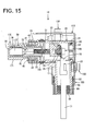
- the direction at an angle different from 0° or 180°, preferably substantially perpendicular to the fitting direction means a direction at an angle different from 0° or 180°, preferably substantially perpendicular to a direction in which the fitting portion 21 is fitted into the case-side opening 161 and is, for example, the lateral direction (shown lateral direction in FIG. 4 ) or the vertical direction (shown vertical direction in FIG. 15 ), but not limited only to the lateral direction and the vertical direction.
- a loosely movable distance of the terminal accommodating portion 30 is determined by a dimension of a clearance CL formed between the terminal accommodating portion 30 and the inner peripheral surface of the insertion hole 41.
- a part of the terminal accommodating portion 30 at least partly covered by the insertion hole 41 is formed to be one size smaller than the insertion hole 41 of the retainer 40 and, accordingly, the clearance CL is formed (particularly substantially over the entire circumference) around the terminal accommodating portion 30.
- the terminal accommodating portion 30 is freely movable within the formation range of the clearance CL.
- a conceivable configuration for loosely movably mounting a terminal accommodating portion into a fitting portion is, for example, to provide a flexible piece on the terminal accommodating portion and mount the terminal accommodating portion by engaging this flexible piece with the housing 20.
- the terminal accommodating portion can be loosely moved relative to the fitting portion by deflecting the flexible piece.
- a large deflection amount needs to be ensured to ensure a clearance for allowing loose movements of the terminal accommodating portion, which may lead to the enlargement of the terminal accommodating portion.
- the clearance CL particularly only has to be set to have a dimension necessary to absorb a tolerance and can be easily set without enlarging the terminal accommodating portion 30. This can contributes to the miniaturization of the connector 10.
- a part of the terminal accommodating portion 30 projecting forward from the fitting portion 21 serves as a projecting portion 36.
- this projecting portion 36 can be at least partly accommodated into the receptacle 171 of the device-side connector 170.
- the terminal accommodating portion 30 can be moved in accordance with this position of the receptacle 171 and the projecting portion 36 can be fitted into the receptacle 171.
- the male terminal(s) 172 is/are fitted into the female terminals 52 and/or the resilient contact piece(s) resiliently come(s) into contact with the male terminal(s) 172. In this way, the terminals 52, 172 can be properly connected by absorbing the mounting tolerance of the device-side connector 170.
- the flange(s) 33 particularly is/are sandwiched in forward and backward directions FBD between the rear surface of the holding tube 42 of the retainer 40 and the rear end part of the mounting recess 28 of the fitting portion 21, but softly sandwiched so as not to hinder loose movements of the terminal accommodating portion 30.
- a clearance having the same dimension as the above clearance CL particularly is formed between the outer peripheral edges of the flange(s) 33 and the inner surface of the mounting recess 28. This clearance is so set that the flange(s) 33 can be held in contact with the rear end part of the mounting recess 28 even if the terminal accommodating portion 30 is loosely moved to a maximum extent. Further, as shown in FIG.
- At least one partition wall 23A partitioning the respective accommodation spaces 23 of the housing 20 at least partly is inserted into a clearance between the respective terminal accommodating tubes 31 of the terminal accommodating portion 30 to be located behind the coupling portion 32, thereby forming an uneven shape.
- a creepage distance (insulating property) between the respective stretchable conductors 51 is ensured.
- the intermediate terminals 72 are connected (particularly crimped or bent or folded) to end(s) of the respective wire(s) 71 to form the outer conductive member(s) 70.
- the female terminal(s) 52 is/are connected (particularly crimped or bent or folded) to one end side(s) of the stretchable conductor(s) 51 and the (particularly bent or L-shaped) terminal(s) 53 is/are connected (particularly crimped or bent or folded) to the other end side(s) to form the inner conductive member(s) 50 (see FIG. 1 ).
- the locking lance(s) 35 is/are resiliently at least partly restored and engaged with the female terminal(s) 52, particularly with the rear end(s) of the (particularly substantially rectangular or polygonal) tube portion(s), whereby the female terminal(s) 52 is/are retained.
- the (particularly substantially round) terminal portion(s) of the (particularly substantially bent or L-shaped) terminal(s) 53 at least partly is/are placed on the terminal fixing portion 24 of the housing 20.
- the (round) terminal portion(s) of the intermediate terminal(s) 72 at least partly is/are placed on that/those of the (bent or L-shaped) terminal(s) 53 placed on the terminal fixing portion 24 of the housing 20.
- the one or more resilient or rubber plugs 80 are fitted through a lower end opening of the lower member 100 and the resilient or rubber plug presser 90 is mounted below the resilient or rubber plug(s) 80 to hold the resilient or rubber plug(s) 80.
- the fixing screw(s) 140 is/are inserted into the respective (round) terminal portions of the terminal(s) 53 and the intermediate terminal(s) 72 through the operation hole 62 and, subsequently, the tool is inserted to tighten the fixing screw(s) 140 into the fixing nut(s) 25 of the terminal fixing portion 24, thereby fixing the (L-shaped or bent) terminal(s) 53 and the intermediate terminal(s) 72 to the housing 20 (see FIG. 8 ).
- the cover 60 is mounted to substantially close the operation hole 62 and the interior of the housing 20 is sealed by the seal ring or member 61.
- the lower member 100 having the wire(s) 71 inserted therethrough is externally mounted on the wire pullout portion 22 of the housing 20.
- the upper member 110 is mounted particularly substantially from the rear side of the housing 20.
- the respective members 100, 110 are placed at least partly one over the other on the shell coupling portion 27 and the coupling screw 150 is tightened into the fixing nut 25 to fix the respective members 100, 110 to the housing 20 (see FIG. 16 ).
- the both members 100, 110 are united or integral to form the shield shell and the housing 20 at least partly is covered by this shield shell.
- the fitting portion 21 of the housing 20 at least partly is fitted or inserted into the case-side opening 161 of the shield case 160.
- the device-side connector 170 particularly may be mounted with a specified (predetermined or predeterminable) mounting tolerance with respect to the case-side opening 161.
- the fitting portion 21 is mounted substantially in accordance with the position of the case-side opening 161 and the terminal accommodating portion 30 is mounted substantially in accordance with the position of the receptacle 171 of the device-side connector 170.
- the terminal accommodating portion 30 particularly is loosely movable relative to the fitting portion 21 in the direction perpendicular to the fitting direction, the male terminal(s) 172 and the female terminal(s) 52 can be fitted or mated and properly connected while the mounting tolerance of the device-side connector 170 is absorbed. Further, since the stretchable conductors 51 particularly are also freely deflected according to the movement of the terminal accommodating portion 30, free movements of the terminal accommodating portion 30 are not hindered.
- the terminal accommodating portion 30 particularly is loosely movable relative to the fitting portion 21 in the direction at an angle different from 0° or 180°, preferably substantially perpendicular to the fitting direction in a state where the fitting portion 21 of the housing 20 is fitted in the case-side opening 161, the female terminals 52 can be moved in accordance with the positions of the male terminals 172 and the male terminals 172 and the female terminals 52 can be properly connected.
- the terminal accommodating portion 30 particularly may be mounted in the housing 20 to project more forward in the fitting direction than the fitting portion 21 and/or include the projecting portion 36 projecting forward from the fitting portion 21 in the fitting direction and the device-side connector 170 may include the receptacle 171 capable of accommodating the projecting portion 36 inside.
- the projecting portion 36 particularly can be accommodated in the receptacle 171 when the terminal accommodating portion 30 is fitted into the case-side opening 161.
- the mounting position (standby position) of the device-side connector 170 is located more backward than the case-side opening 161 (reliable visual confirmation during an operation is difficult)
- a fitting operation becomes easier and, consequently, connection reliability is improved.
- the male terminal(s) 172 may be configured to be at least partly fittable into the female terminal(s) 52.
- the male terminals 172 particularly can be fitted into the female terminals 52 by fitting the fitting portion 21 into the case-side opening 161.
- the number of operation steps and a space necessary for the fitting operation can be reduced, for example, as compared with a conventional bolt tightening type of connecting conductor-side terminals including a male tab to the male terminals 172.
- the stretchable conductor(s) 51 and the wire(s) 71 particularly extend from the female terminal(s) 52 toward the other end part of the housing 20. Out of these, the stretchable conductor(s) 51 may be stretchable in an extending direction.
- the impact of vibration and the like transmitted from the wire(s) 71 to the female terminal(s) 52 can be absorbed by the stretchable conductor(s) 51, which particularly restrains the impact of vibration and the like of the wire(s) 71 from being exerted from the female terminal(s) 52 to the male terminal(s) 172. This can prevent a defect in connected parts of the terminals 172, 52 due to vibration and the like from the wires 71.
- the terminal accommodating portion 30 particularly may be configured to be mounted into the fitting portion 21 and include the retainer 40 for holding the terminal accommodating portion 30 in the fitting portion 21.
- the terminal accommodating portion 30 can be held mounted in the fitting portion 21 by the retainer 40 and forward detachment of the terminal accommodating portion 30 can be suppressed.
- a connector 10 in which one or more female terminals 52 to be connected to one or more respective male terminals 172 by being fitted into a case-side opening 161 are arranged inside, the male terminal(s) 172 particularly being provided in a device-side connector 170 formed separately from a shield case 160 and mounted in a back side of the case-side opening 161.
- the connector 10 includes a housing 20 which includes a fitting portion 21, which is fittable into the case-side opening 161, in one end part and from the other end part of which one or more stretchable conductors 51 and one or more wires 71 connected to the female terminal(s) 52 are pulled out, and a terminal accommodating portion 30 which is formed particularly separately from the fitting portion 21 and at least partly accommodates the female terminal(s) 52 inside.
- the terminal accommodating portion 30 is mounted into the housing 20 loosely movably in a direction intersecting with a fitting direction of the fitting portion 21 into the case-side opening 161 in connecting the male terminal(s) 172 and the female terminal(s) 52.
Landscapes
- Details Of Connecting Devices For Male And Female Coupling (AREA)
- Connector Housings Or Holding Contact Members (AREA)
- Coupling Device And Connection With Printed Circuit (AREA)
Applications Claiming Priority (1)
| Application Number | Priority Date | Filing Date | Title |
|---|---|---|---|
| JP2012161667A JP2014022266A (ja) | 2012-07-20 | 2012-07-20 | コネクタ |
Publications (1)
| Publication Number | Publication Date |
|---|---|
| EP2688156A1 true EP2688156A1 (de) | 2014-01-22 |
Family
ID=48484979
Family Applications (1)
| Application Number | Title | Priority Date | Filing Date |
|---|---|---|---|
| EP13002716.2A Withdrawn EP2688156A1 (de) | 2012-07-20 | 2013-05-24 | Steckverbinder |
Country Status (4)
| Country | Link |
|---|---|
| US (1) | US9209582B2 (de) |
| EP (1) | EP2688156A1 (de) |
| JP (1) | JP2014022266A (de) |
| CN (1) | CN103579870B (de) |
Cited By (5)
| Publication number | Priority date | Publication date | Assignee | Title |
|---|---|---|---|---|
| EP2701245A3 (de) * | 2012-08-20 | 2015-02-18 | Sumitomo Wiring Systems, Ltd. | Steckverbinder und Produktionsverfahren dafür |
| EP2670005B1 (de) * | 2012-05-28 | 2018-03-28 | AutoNetworks Technologies, Ltd. | Stecker und Herstellungsverfahren dafür |
| DE112013007549B4 (de) | 2013-10-31 | 2018-09-06 | Yazaki Corporation | Verbinder |
| WO2019206933A1 (de) * | 2018-04-24 | 2019-10-31 | Phoenix Contact Gmbh & Co. Kg | Elektrischer verbinder |
| EP3605748A4 (de) * | 2017-04-13 | 2020-03-25 | Huawei Technologies Co., Ltd. | Funkfrequenzverbinder |
Families Citing this family (30)
| Publication number | Priority date | Publication date | Assignee | Title |
|---|---|---|---|---|
| JP5668983B2 (ja) * | 2011-04-05 | 2015-02-12 | 株式会社オートネットワーク技術研究所 | コネクタ |
| US20140065880A1 (en) * | 2012-09-04 | 2014-03-06 | Remy Technologies, Llc | Interchangeable magnetic switch shield connector |
| WO2014069285A1 (ja) * | 2012-10-30 | 2014-05-08 | 矢崎総業株式会社 | コネクタ |
| US9257772B2 (en) * | 2013-02-08 | 2016-02-09 | Lear Corporation | Electric connector with a lock to retain a terminal within a housing |
| JP2015162327A (ja) | 2014-02-27 | 2015-09-07 | 住友電装株式会社 | 防水コネクタ |
| JP6335075B2 (ja) * | 2014-09-05 | 2018-05-30 | タイコエレクトロニクスジャパン合同会社 | コネクタ |
| JP6269418B2 (ja) * | 2014-09-29 | 2018-01-31 | 株式会社オートネットワーク技術研究所 | 機器用コネクタ |
| DE102014015148B4 (de) * | 2014-10-13 | 2018-11-29 | Sumitomo Wiring Systems, Ltd. | Ladeverbinder und Verfahren zum Montieren desselben |
| JP6492929B2 (ja) * | 2015-04-23 | 2019-04-03 | 住友電装株式会社 | コネクタ |
| JP6402933B2 (ja) * | 2015-05-12 | 2018-10-10 | 株式会社オートネットワーク技術研究所 | コネクタ、及び、コネクタ接続構造 |
| US9455523B1 (en) * | 2015-08-05 | 2016-09-27 | Delphi Technologies, Inc. | Right angle connection assembly |
| JP6575340B2 (ja) * | 2015-12-09 | 2019-09-18 | 住友電装株式会社 | コネクタ |
| JP6349345B2 (ja) * | 2016-05-20 | 2018-06-27 | 矢崎総業株式会社 | プラグコネクタ及び電源回路遮断装置 |
| JP6678521B2 (ja) * | 2016-06-02 | 2020-04-08 | 日本航空電子工業株式会社 | コネクタ組立体およびコネクタ組立体の実装構造 |
| JP6434938B2 (ja) * | 2016-08-10 | 2018-12-05 | 矢崎総業株式会社 | コネクタ |
| DE102017100538B3 (de) * | 2017-01-12 | 2018-05-09 | Knorr-Bremse Systeme für Nutzfahrzeuge GmbH | Elektrische Steckverbindung aus einem Stecker und einem Gegenstecker sowie elektrische oder elektro-pneumatische Bremseinrichtung eines Fahrzeugs |
| JP6317844B1 (ja) * | 2017-05-30 | 2018-04-25 | イリソ電子工業株式会社 | コネクタ |
| JP6937081B2 (ja) * | 2017-05-30 | 2021-09-22 | イリソ電子工業株式会社 | コネクタ |
| US10505304B2 (en) * | 2017-06-26 | 2019-12-10 | Astec International Limited | Movable power connections for power supplies |
| JP6936970B2 (ja) * | 2017-10-16 | 2021-09-22 | 住友電装株式会社 | 筐体内回路体に対するワイヤハーネスの接続構造 |
| JP6926998B2 (ja) * | 2017-12-05 | 2021-08-25 | トヨタ自動車株式会社 | 電気機器の車載構造 |
| JP6616815B2 (ja) * | 2017-12-20 | 2019-12-04 | 矢崎総業株式会社 | コネクタ及びコネクタ付き電線 |
| JP7042421B2 (ja) * | 2018-11-19 | 2022-03-28 | 株式会社オートネットワーク技術研究所 | コネクタ、及びコネクタ付きワイヤハーネス |
| JP7027011B2 (ja) * | 2019-06-25 | 2022-03-01 | 矢崎総業株式会社 | コネクタ |
| JP7328624B2 (ja) * | 2020-02-04 | 2023-08-17 | 株式会社オートネットワーク技術研究所 | 端子接続ユニット |
| DE102020111777A1 (de) * | 2020-04-30 | 2021-11-04 | Purem GmbH | Anschlusseinheit zum Anschließen einer elektrischen Versorgungsleitung an ein Anschlusselement einer beheizbaren Abgasanlage |
| JP7191487B2 (ja) * | 2020-08-13 | 2022-12-19 | 矢崎総業株式会社 | コネクタ |
| JP7282814B2 (ja) * | 2021-01-08 | 2023-05-29 | 矢崎総業株式会社 | ワイヤハーネス |
| JP7524830B2 (ja) | 2021-05-28 | 2024-07-30 | 住友電装株式会社 | コネクタ |
| JP7521488B2 (ja) | 2021-05-28 | 2024-07-24 | 住友電装株式会社 | コネクタ |
Citations (2)
| Publication number | Priority date | Publication date | Assignee | Title |
|---|---|---|---|---|
| JP2000277217A (ja) | 1999-03-19 | 2000-10-06 | Smk Corp | フローティングコネクタ |
| US20060240716A1 (en) * | 2005-04-01 | 2006-10-26 | Yazaki Corporation | Connector |
Family Cites Families (14)
| Publication number | Priority date | Publication date | Assignee | Title |
|---|---|---|---|---|
| US3510963A (en) * | 1968-08-28 | 1970-05-12 | Hickok Teaching Systems Inc | Teaching system |
| US3562696A (en) * | 1969-01-17 | 1971-02-09 | Amp Inc | Multicontact connector having improved insert |
| US4580862A (en) * | 1984-03-26 | 1986-04-08 | Amp Incorporated | Floating coaxial connector |
| US6379162B1 (en) * | 2000-07-27 | 2002-04-30 | Delphi Technologies, Inc. | Electrical connector system |
| JP4955754B2 (ja) * | 2007-03-02 | 2012-06-20 | 株式会社オートネットワーク技術研究所 | シールドシェル |
| JP4959505B2 (ja) * | 2007-10-24 | 2012-06-27 | 日本圧着端子製造株式会社 | 掛け止め金具付きコネクタハウジング、掛け止め金具付きコネクタ及び電気コネクタ装置 |
| JP4961331B2 (ja) * | 2007-11-27 | 2012-06-27 | 矢崎総業株式会社 | 電磁波シールドコネクタ |
| CN102341969B (zh) * | 2009-03-25 | 2016-06-29 | 矢崎总业株式会社 | 连接器 |
| JP5303378B2 (ja) * | 2009-06-26 | 2013-10-02 | 矢崎総業株式会社 | 待ち受けコネクタ |
| JP5399804B2 (ja) * | 2009-08-03 | 2014-01-29 | 矢崎総業株式会社 | コネクタ |
| JP5423233B2 (ja) * | 2009-08-18 | 2014-02-19 | 住友電装株式会社 | コネクタ |
| JP5467850B2 (ja) * | 2009-12-03 | 2014-04-09 | 矢崎総業株式会社 | L字型コネクタ |
| CN201699217U (zh) * | 2010-06-02 | 2011-01-05 | 亮泰企业股份有限公司 | 易于卸装导电端子的连接器 |
| US8777647B2 (en) * | 2010-12-07 | 2014-07-15 | Delta Systems, Inc. | Connection system and method |
-
2012
- 2012-07-20 JP JP2012161667A patent/JP2014022266A/ja not_active Abandoned
-
2013
- 2013-05-24 EP EP13002716.2A patent/EP2688156A1/de not_active Withdrawn
- 2013-07-18 US US13/944,931 patent/US9209582B2/en active Active
- 2013-07-22 CN CN201310308490.7A patent/CN103579870B/zh active Active
Patent Citations (2)
| Publication number | Priority date | Publication date | Assignee | Title |
|---|---|---|---|---|
| JP2000277217A (ja) | 1999-03-19 | 2000-10-06 | Smk Corp | フローティングコネクタ |
| US20060240716A1 (en) * | 2005-04-01 | 2006-10-26 | Yazaki Corporation | Connector |
Cited By (7)
| Publication number | Priority date | Publication date | Assignee | Title |
|---|---|---|---|---|
| EP2670005B1 (de) * | 2012-05-28 | 2018-03-28 | AutoNetworks Technologies, Ltd. | Stecker und Herstellungsverfahren dafür |
| EP2701245A3 (de) * | 2012-08-20 | 2015-02-18 | Sumitomo Wiring Systems, Ltd. | Steckverbinder und Produktionsverfahren dafür |
| DE112013007549B4 (de) | 2013-10-31 | 2018-09-06 | Yazaki Corporation | Verbinder |
| EP3605748A4 (de) * | 2017-04-13 | 2020-03-25 | Huawei Technologies Co., Ltd. | Funkfrequenzverbinder |
| US10819069B2 (en) | 2017-04-13 | 2020-10-27 | Huawei Technologies Co., Ltd. | Radio frequency connector |
| WO2019206933A1 (de) * | 2018-04-24 | 2019-10-31 | Phoenix Contact Gmbh & Co. Kg | Elektrischer verbinder |
| BE1026231B1 (de) * | 2018-04-24 | 2019-11-25 | Phoenix Contact Gmbh & Co | Elektrischer verbinder |
Also Published As
| Publication number | Publication date |
|---|---|
| US9209582B2 (en) | 2015-12-08 |
| US20140024266A1 (en) | 2014-01-23 |
| CN103579870A (zh) | 2014-02-12 |
| JP2014022266A (ja) | 2014-02-03 |
| CN103579870B (zh) | 2016-12-07 |
Similar Documents
| Publication | Publication Date | Title |
|---|---|---|
| EP2688156A1 (de) | Steckverbinder | |
| US9124024B2 (en) | Connector having inner conductive member | |
| US9312626B2 (en) | Shield connector | |
| US9455525B2 (en) | Connector with flexible conductive member to isolate terminal from vibrations in a wire | |
| US8485844B2 (en) | L-shaped connector | |
| US9472893B1 (en) | Connector | |
| US9257772B2 (en) | Electric connector with a lock to retain a terminal within a housing | |
| US9287649B2 (en) | Connector and housing | |
| WO2013047178A1 (ja) | ジョイントコネクタ | |
| JP2018524785A (ja) | 端子金具 | |
| JP6943175B2 (ja) | 端子金具及びコネクタ | |
| US10714868B2 (en) | Waterproof connector for a board | |
| US10038271B2 (en) | Electrical connector with reduced size in a direction perpendicular to the arrangement and extending directions of two wires | |
| US8641441B2 (en) | Connector | |
| JP5585106B2 (ja) | コネクタ装置 | |
| WO2016121565A1 (ja) | シールドコネクタ | |
| JP2002280131A (ja) | 機器接続用シールドコネクタ | |
| EP2768088A1 (de) | Abgeschirmter steckverbinder | |
| JP2019220255A (ja) | 端子 | |
| CN110311248A (zh) | 连接器 | |
| EP4117123A1 (de) | Verbinderbefestigungskonstruktion | |
| JP2017050094A (ja) | コネクタの防水構造 | |
| US11374365B2 (en) | Electrical device connector with shielding for mounting on a case of a device | |
| US7607945B2 (en) | Connector | |
| CN114175413A (zh) | 连接器 |
Legal Events
| Date | Code | Title | Description |
|---|---|---|---|
| PUAI | Public reference made under article 153(3) epc to a published international application that has entered the european phase |
Free format text: ORIGINAL CODE: 0009012 |
|
| AK | Designated contracting states |
Kind code of ref document: A1 Designated state(s): AL AT BE BG CH CY CZ DE DK EE ES FI FR GB GR HR HU IE IS IT LI LT LU LV MC MK MT NL NO PL PT RO RS SE SI SK SM TR |
|
| AX | Request for extension of the european patent |
Extension state: BA ME |
|
| 17P | Request for examination filed |
Effective date: 20140528 |
|
| RBV | Designated contracting states (corrected) |
Designated state(s): AL AT BE BG CH CY CZ DE DK EE ES FI FR GB GR HR HU IE IS IT LI LT LU LV MC MK MT NL NO PL PT RO RS SE SI SK SM TR |
|
| GRAP | Despatch of communication of intention to grant a patent |
Free format text: ORIGINAL CODE: EPIDOSNIGR1 |
|
| INTG | Intention to grant announced |
Effective date: 20160707 |
|
| RAP1 | Party data changed (applicant data changed or rights of an application transferred) |
Owner name: SUMITOMO WIRING SYSTEMS, LTD. |
|
| RIN1 | Information on inventor provided before grant (corrected) |
Inventor name: MATSUOKA, HIROYUKI Inventor name: KASHIWADA, TOMOKAZU |
|
| STAA | Information on the status of an ep patent application or granted ep patent |
Free format text: STATUS: THE APPLICATION IS DEEMED TO BE WITHDRAWN |
|
| 18D | Application deemed to be withdrawn |
Effective date: 20161118 |