EP2671494A1 - Geschirrspülmaschine - Google Patents
Geschirrspülmaschine Download PDFInfo
- Publication number
- EP2671494A1 EP2671494A1 EP13170691.3A EP13170691A EP2671494A1 EP 2671494 A1 EP2671494 A1 EP 2671494A1 EP 13170691 A EP13170691 A EP 13170691A EP 2671494 A1 EP2671494 A1 EP 2671494A1
- Authority
- EP
- European Patent Office
- Prior art keywords
- unit
- water
- liquid ejection
- dish
- washing machine
- Prior art date
- Legal status (The legal status is an assumption and is not a legal conclusion. Google has not performed a legal analysis and makes no representation as to the accuracy of the status listed.)
- Granted
Links
- 238000004851 dishwashing Methods 0.000 title claims abstract description 48
- XLYOFNOQVPJJNP-UHFFFAOYSA-N water Substances O XLYOFNOQVPJJNP-UHFFFAOYSA-N 0.000 claims abstract description 92
- 239000007788 liquid Substances 0.000 claims abstract description 78
- 238000005406 washing Methods 0.000 claims abstract description 65
- 238000011109 contamination Methods 0.000 description 4
- 239000000470 constituent Substances 0.000 description 3
- 239000003599 detergent Substances 0.000 description 3
- 238000009434 installation Methods 0.000 description 3
- 229910000831 Steel Inorganic materials 0.000 description 1
- 239000003575 carbonaceous material Substances 0.000 description 1
- 230000003247 decreasing effect Effects 0.000 description 1
- 238000001035 drying Methods 0.000 description 1
- 230000000694 effects Effects 0.000 description 1
- 239000010959 steel Substances 0.000 description 1
Images


Classifications
-
- A—HUMAN NECESSITIES
- A47—FURNITURE; DOMESTIC ARTICLES OR APPLIANCES; COFFEE MILLS; SPICE MILLS; SUCTION CLEANERS IN GENERAL
- A47L—DOMESTIC WASHING OR CLEANING; SUCTION CLEANERS IN GENERAL
- A47L15/00—Washing or rinsing machines for crockery or tableware
- A47L15/14—Washing or rinsing machines for crockery or tableware with stationary crockery baskets and spraying devices within the cleaning chamber
-
- A—HUMAN NECESSITIES
- A47—FURNITURE; DOMESTIC ARTICLES OR APPLIANCES; COFFEE MILLS; SPICE MILLS; SUCTION CLEANERS IN GENERAL
- A47L—DOMESTIC WASHING OR CLEANING; SUCTION CLEANERS IN GENERAL
- A47L15/00—Washing or rinsing machines for crockery or tableware
- A47L15/02—Washing or rinsing machines for crockery or tableware with circulation and agitation of the cleaning liquid in the cleaning chamber containing a stationary basket
- A47L15/06—Washing or rinsing machines for crockery or tableware with circulation and agitation of the cleaning liquid in the cleaning chamber containing a stationary basket by means of an impeller in the chamber
-
- A—HUMAN NECESSITIES
- A47—FURNITURE; DOMESTIC ARTICLES OR APPLIANCES; COFFEE MILLS; SPICE MILLS; SUCTION CLEANERS IN GENERAL
- A47L—DOMESTIC WASHING OR CLEANING; SUCTION CLEANERS IN GENERAL
- A47L15/00—Washing or rinsing machines for crockery or tableware
- A47L15/14—Washing or rinsing machines for crockery or tableware with stationary crockery baskets and spraying devices within the cleaning chamber
- A47L15/16—Washing or rinsing machines for crockery or tableware with stationary crockery baskets and spraying devices within the cleaning chamber with rigidly-mounted spraying devices
-
- A—HUMAN NECESSITIES
- A47—FURNITURE; DOMESTIC ARTICLES OR APPLIANCES; COFFEE MILLS; SPICE MILLS; SUCTION CLEANERS IN GENERAL
- A47L—DOMESTIC WASHING OR CLEANING; SUCTION CLEANERS IN GENERAL
- A47L15/00—Washing or rinsing machines for crockery or tableware
- A47L15/14—Washing or rinsing machines for crockery or tableware with stationary crockery baskets and spraying devices within the cleaning chamber
- A47L15/18—Washing or rinsing machines for crockery or tableware with stationary crockery baskets and spraying devices within the cleaning chamber with movably-mounted spraying devices
-
- A—HUMAN NECESSITIES
- A47—FURNITURE; DOMESTIC ARTICLES OR APPLIANCES; COFFEE MILLS; SPICE MILLS; SUCTION CLEANERS IN GENERAL
- A47L—DOMESTIC WASHING OR CLEANING; SUCTION CLEANERS IN GENERAL
- A47L15/00—Washing or rinsing machines for crockery or tableware
- A47L15/42—Details
-
- A—HUMAN NECESSITIES
- A47—FURNITURE; DOMESTIC ARTICLES OR APPLIANCES; COFFEE MILLS; SPICE MILLS; SUCTION CLEANERS IN GENERAL
- A47L—DOMESTIC WASHING OR CLEANING; SUCTION CLEANERS IN GENERAL
- A47L15/00—Washing or rinsing machines for crockery or tableware
- A47L15/42—Details
- A47L15/4278—Nozzles
- A47L15/4282—Arrangements to change or modify spray pattern or direction
-
- B—PERFORMING OPERATIONS; TRANSPORTING
- B08—CLEANING
- B08B—CLEANING IN GENERAL; PREVENTION OF FOULING IN GENERAL
- B08B3/00—Cleaning by methods involving the use or presence of liquid or steam
Definitions
- the present invention relates to a dish washing machine having a structure allowing water to be evenly ejected onto the interior of a washing tub.
- a dish washing machine also referred to as a dishwasher, which generally washes dishes by ejecting high-pressure water onto dishes, usually performs operations of preliminary washing, main washing, rinsing, and drying.
- preliminary washing water having no detergent introduced thereinto is ejected to remove debris from the dishes.
- main washing the dishes are cleaned with detergent introduced into the ejected water by a detergent feeder.
- the dish washing machine generally includes a cabinet provided therein with a washing tub, a dish basket adapted to retain dishes and installed in the washing tub to be movable forward and backward, and a liquid ejection unit to eject water onto the dish basket.
- the dishes are washed by the water ejected by the liquid ejection unit.
- the dish basket includes an upper dish basket arranged at an upper portion of the washing tub, and a lower dish basket arranged at a lower portion of the washing tub.
- liquid ejection units are positioned at the upper side of the upper dish basket, and at the upper and lower sides of the lower dish basket. In the case that the liquid ejection units are rotatably arranged, there may be dead zones at the corners of the rectangular washing tub which the ejected water does not reach.
- a liquid ejection unit having a variable length or having a rotatable structure has been proposed to eliminate dead zones which the water does not reach.
- This eject nozzle may eliminate the dead zones, but may not obtain the effect of divided or intensive washing.
- the liquid ejection unit allowing the water to reach the dead zones by changing the direction in which the liquid ejection unit extends, when the direction of the liquid ejection unit is perpendicular to the wall of the washing tub, the water is directed to the wall of the washing tub, and thereby the liquid ejection unit may fail to wash the dishes, and further noise from the liquid ejection unit may increase.
- a dish washing machine which may eliminate dead zones which the water does reach by including a liquid ejection unit to eject water toward the dish basket and a deflection unit adapted to deflect the water.
- a dish washing machine includes a cabinet forming an external appearance of the dish washing machine, a washing tub arranged in the cabinet and allowing dishes to be washed therein, a dish basket arranged in the washing tub to accommodate the dishes, at least one liquid ejection unit arranged in the washing tub to eject water onto the dish basket, a deflection unit arranged facing the liquid ejection unit to deflect the water ejected from the liquid ejection unit, and a drive unit to drive the deflection unit to be movable within the washing tub.
- the liquid ejection unit may include a body extending in a first direction and a plurality of liquid ejecting heads provided on the body, and the drive unit may be operable to move the deflection unit forward and backward in a second direction perpendicular to the first direction while water is being ejected by the liquid ejection unit.
- the deflection unit may be disposed at at least one of upper and lower sides of the dish basket to deflect the water ejected from the liquid ejection unit toward the dish basket.
- the deflection unit may include a concave portion having a surface to contact the water ejected from the liquid ejection unit, the surface being concavely formed to deflect the water toward the dish basket.
- the concave portion may be formed in a shape of a curved surface to deflect the water.
- the concave portion may include at least one bent portion bent along a longitudinal direction of the deflection unit to deflect the water in various directions.
- a plurality of grooves may be provided at an inner side of the concave portion to guide deflection of the water.
- the grooves may be formed only at a portion of the concave portion to guide deflection of the water toward the dishes.
- the drive unit may include a rail coupled to the deflection unit to guide movement of the deflection unit, and a power generating unit to drive the deflection unit.
- the drive unit may further include a pulley or a gear coupled to the power generating unit, and the drive unit and the deflection unit are connected to each other through a connection member.
- the rail may be arranged at opposite walls facing each other in the washing tub to guide the movement of the deflection unit.
- the liquid ejection unit may be arranged at a rear surface of the washing tub.
- a dish washing machine including a washing tub to wash dishes and a dish basket arranged in the washing tub to accommodate the dishes, includes a liquid ejection unit positioned at a lower side of the dish basket and adapted to eject water in a first direction, and a deflection unit to deflect the water from the liquid ejection unit in a second direction toward the dishes.
- the deflection unit may include a concave portion concavely formed to deflect the water from the first direction to the second direction.
- the dish washing machine may further include a drive unit to drive the deflection unit to move between front and rear surfaces of the washing tub or between left and right surfaces of the washing tub.
- the drive unit may include a rail coupled to the deflection unit to guide movement of the deflection unit, a motor to drive the deflection unit, a pulley or gear coupled to the motor, and a connection member to connect the pulley or gear to the defection unit.
- the deflection unit may be moved toward the liquid ejection unit by the connection member and may be moved away from the liquid ejection unit by a pressure of the water ejected from the liquid ejection unit.
- a dish washing machine includes a cabinet forming an external appearance of the dish washing machine, a washing tub arranged in the cabinet and allowing dishes to be washed therein, a liquid ejection unit positioned at at least one surface of the washing tub and adapted to eject water in a direction substantially parallel with the dish basket, a deflection unit provided with a concave portion at a surface thereof to contact the water ejected from the liquid ejection unit to deflect the water to a direction substantially perpendicular to a direction in which the water is ejected from the liquid ejection unit, and a drive unit including a rail coupled to the deflection unit to allow the deflection unit to move toward or away from the liquid ejection unit, and a motor to move the deflection unit, wherein at least one of a state in which the deflection unit is moved toward the liquid ejection unit and a state in which the deflection unit is moved away from the liquid ejection unit is achieved by
- the drive unit may further include a pulley coupled to the motor, and a connection member to connect the pulley to the deflection unit.
- FIG. 1 is a cross-sectional view illustrating the configuration of a dish washing machine according to an exemplary embodiment of the present disclosure.
- the dish washing machine 1 includes a cabinet 2 forming an external appearance of the dish washing machine 1, and a washing tub 4 arranged in the cabinet 2 to wash dishes.
- a sump 43 allowing water to be stored therein is provided at the lower portion of the washing tub 4.
- the front of the cabinet 2 is open to allow dishes to be placed in or withdrawn from the washing tub 4.
- a door 3 is installed at the front of the cabinet 2 to open and close the washing tub 4.
- the door 3 is hinged to the front lower portion of the cabinet 2 to open and close the washing tub 4 by rotation.
- a pair of dish baskets 7 provided with a receipt part having an open upper side to receive dishes is installed at the upper and lower portions of the inside of the washing tub 4 such that the dish baskets 7 are movable forward and backward.
- the dish baskets 7 are allowed to be placed in or withdrawn from the cabinet 2 through the open front of the cabinet 2 by at least one rack 10 slidably supporting the dish baskets 7.
- the rack 10 may include an upper rack 8 and a lower rack 9 to support an upper dish basket 5 and a lower dish basket 6, respectively, but embodiments of the present disclosure are not limited thereto.
- the dish baskets 7 are formed by wires arranged in a lattice pattern to allow dishes accommodated in the dish baskets 7 to be exposed outside the dish baskets 7 to be washed.
- Liquid ejection units 13 and 19 to eject water to the dish baskets 7 are mounted to at least one surface of the washing tub 4.
- the liquid ejection units 13 and 19 may include an upper liquid ejection unit 13 and a lower liquid ejection unit 19 to eject water respectively onto an upper dish basket 5 and a lower dish basket 6, but embodiments of the present disclosure are not limited thereto.
- At least one liquid ejection unit 13, 19 may be provided on at least one surface of the washing tub 4.
- the liquid ejection units 13 and 19 may be arranged to eject water onto the lower ends of the dish baskets 7.
- Deflection units 20 and 25 to deflect water ejected by the liquid ejection units 13 and 19 are provided in the washing tub 4.
- the deflection units 20 and 25 may be arranged to face the liquid ejection units 13 and 19.
- the deflection units 20 and 25 may be positioned at the lower ends of the dish baskets 7.
- embodiments of the present disclosure are not limited thereto.
- the deflection units 20 and 25 may be positioned at the upper sides or lower sides of the dish baskets 7.
- the dish washing machine 1 may further include a drive unit to drive the deflection units 20 and 25 to move within the washing tub 4.
- the drive unit may include a rail 31 coupled to the deflection units 20 and 25 and a power generating unit 35 and pulley 34 to drive the deflection units 20 and 25.
- the drive unit may further include a connection member 33 to connect the pulley 34 to the deflection units 20 and 25, which will be described later.
- the washing tub 4 may be provided with a heater 44 and heater installation groove 45 to heat water.
- the heater installation groove 45 is provided at the bottom of the washing tub 4, and the heater 44 is installed at the heater installation groove 45.
- the sump 43 is arranged at the center of the bottom of the washing tub 4 to collect and pump water.
- the sump 43 includes a wash pump 42 to pump water at high pressure, and a pump motor 41 to drive the wash pump 42.
- a drain pump 46 to drain water is provided at the bottom of the washing tub 4.
- the wash pump 42 pumps out water toward the upper liquid ejection unit 13 through a first supply pipe 11 and pumps out water toward the lower liquid ejection unit 19 through a second supply pipe 17. While the first supply pipe 11 and the second supply pipe 17 are illustrated in FIG. 1 as being separately coupled to the sump 43, embodiments of the present disclosure are not limited thereto. That is, the first supply pipe 11 and the second supply pipe 17 may be branched off form one pipe.
- the first supply pipe 11 may be a connector 12, and the connector 12 may be connected to the liquid ejection unit 13.
- the sump 43 may include a turbidity sensor (not shown) to detect a contamination level of water.
- a controller (not shown) of the dish washing machine 1 may detect the contamination level of water using a turbidity sensor (not shown), and control the number of times of performance of washing and rinsing. That is, when the contamination level is high, the number of times of performance of washing and rinsing may be increased. When the contamination level is low, the number of times of performance of washing and rinsing may be decreased.
- FIG. 2 is a perspective view illustrating the liquid ejection unit and deflection unit of the dish washing machine according to the illustrated embodiment
- FIG. 3 is a plan view illustrating the liquid ejection unit and deflection unit of the dish washing machine according to the illustrated embodiment.
- the liquid ejection unit 13 is arranged on one surface of the washing tub 4 to eject water onto the lower end of the dish basket 7.
- the liquid ejection unit 13 may include a body 14 coupled to the washing tub 4, and heads 15 provided with a ejection hole 16 to eject water therethrough.
- the diameter of the ejection hole 16 may be between 5mm and 7mm, and six ejection holes 16 may be provided per liquid ejection unit 13. In this case, the distance from one head 15 to a neighboring head 15 may be between about 80mm and about 90mm.
- the deflection unit 20 is provided to deflect water ejected by the liquid ejection unit 13 and arranged to face the liquid ejection unit 13.
- the deflection unit 20 may include a concave portion 21 (see FIG. 5 ).
- the surface of the concave portion 21 to contact water is concavely formed to deflect water to the dish basket 7.
- the concave portion 21 will be described later.
- Rollers 32 may be provided at the opposite sides of the deflection unit 20.
- the deflection unit 20 may be formed of steel.
- the deflection unit 20 may be coupled to the drive unit which drives the deflection unit 20 to move within the washing tub 4.
- the drive unit may include a rail to guide movement of the deflection unit 20.
- the rollers 32 of the deflection unit 20 are coupled to the rail 31 of the drive unit and are movable between the front and rear surfaces of the washing tub 4 or between left and right surfaces, along the rail 31.
- the rail 31 of the drive unit is coupled to both sidewalls 4a and 4b of the washing tub 4.
- a power generating unit 35 to drive the deflection unit 20 is coupled to the pulley 34.
- a motor may be used.
- the pulley 34 is connected to the deflection unit 20 through the connection member 33.
- As the connection member 33 a braided wire or a long and thin string of a carbon material may be used.
- other constituents such as a gear (not shown) may be provided.
- the pulley 34 may move the deflection unit 20 toward the liquid ejection unit 13 by rotating in one direction and move the deflection unit 20 away from the liquid ejection unit 13 by rotating in the opposite direction. It may be possible to operate the power generating unit 35 in the opposite manner.
- the deflection unit 20 may be moved away from the liquid ejection unit 13 by the pressure of water ejected by the liquid ejection unit 13. In this case, the liquid ejection unit 13 moves using the water, and therefore it may be possible to perform strong and intensive washing using the deflection unit 20 while the dishes are washed.
- the drive unit does not need to be directly connected to the flow channel of water, and therefore a configuration of the dish washing machine 1 simpler than that of conventional cases may be possible.
- FIG. 4 is an enlarged view illustrating main constituents and directions of ejection of water in the dish washing machine according to the illustrated embodiment.
- water is ejected in a first direction D1 toward the dish basket 5 by the liquid ejection unit 13. That is, water is ejected in the direction parallel with the dish basket 5.
- the water contacts the concave portion 21 of the deflection unit 20 and is deflected in a second direction D2, D2', D2" approximately perpendicular to the dish basket 5.
- the dishes 51 and 52 may be efficiently washed.
- the direction of the ejected water may vary. That is, the ejection of water is approximately perpendicular to the dishes 51 and 52. Referring to FIG.
- the dishes placed in the dish basket 5 may be arranged to face in various directions including the traverse direction 51 and longitudinal direction 52, and therefore the deflection unit 20 may deflect water at various angles. Washing of the dishes 51 and 52 is substantially performed by the water deflected to the second direction D2, D2', D2" by the deflection unit 20. Since the deflection unit 20 is movable forward and backward by the drive unit, strong and intensive washing of a specific area of the dishes may be performed depending on movement of the deflection unit 20.
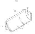
- FIG. 5 is an enlarged perspective view illustrating the deflection unit of the dish washing machine according to the illustrated embodiment.
- the deflection unit 20 may include a concave portion 21 to deflect water. While the concave portion 21 is illustrated in FIG. 5 as being formed in the shape of a curved surface, embodiments of the present disclosure are not limited thereto.
- a rear wall 23 is provided at the rear surface of the concave portion 21, while sidewalls 22 are provide at a lateral side of the concave portion 21.
- the rollers 32 may be coupled to the sidewalls 22.
- the concave portion 21 of the deflection unit 20 guides deflection of the water ejected by the liquid ejection unit 13.
- the water is ejected through the ejection hole 16 of the liquid ejection unit 13 but is guided along the concave portion 21 of the deflection unit 20 and deflected to the second direction D2 to be ejected onto the dishes, and therefore the water ejected onto the dishes has a wider area than when discharged through the ejection hole 16. Accordingly, the possibility of leaving portions of the dishes unwashed may be reduced.
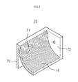
- FIGS. 6 to 8 are enlarged perspective views illustrating a deflection unit according to other embodiments of the present disclosure.
- a concave portion 61 may include at least one bent portion 64 bent along the longitudinal direction of the deflection unit 60 to deflect the ejected water in various directions.
- a bent portion 64 may be bent at various angles in the direction toward the concave portion 61 or the direction away from the concave portion 61. Thereby, the direction of the ejected water may be adjusted.
- a plurality of bent portions 64 may alternatively be provided to eject the water in various directions according to respective portions.
- a deflection unit 70 may be provided with a plurality of grooves 74 at the concave portion 71 to guide deflection of water. When the water contacts the grooves 74, it is deflected along the grooves 74 of the concave portion 71 toward the dishes due to water pressure. In the case that the deflection unit 70 is positioned at the lower side of the dish basket 5, the water is deflected along the concave portion 71 upward.
- a concave portion 81 is provided with two regions. That is, the concave portion 81 may include a first region 85 having no groove and a second region 84 having grooves formed therein. Thereby, the ejected water from the liquid ejection unit 13 is guided along the grooves in the second region 84 and deflected.
- a dish washing machine includes a deflection unit in addition to a liquid ejection unit, and therefore a dead zone which water does not reach may be eliminated and divided and intensive washing may be possible in the washing tub.
Landscapes
- Washing And Drying Of Tableware (AREA)
Applications Claiming Priority (1)
| Application Number | Priority Date | Filing Date | Title |
|---|---|---|---|
| KR1020120060656A KR101737056B1 (ko) | 2012-06-05 | 2012-06-05 | 식기세척기 |
Publications (2)
| Publication Number | Publication Date |
|---|---|
| EP2671494A1 true EP2671494A1 (de) | 2013-12-11 |
| EP2671494B1 EP2671494B1 (de) | 2016-03-02 |
Family
ID=48576291
Family Applications (1)
| Application Number | Title | Priority Date | Filing Date |
|---|---|---|---|
| EP13170691.3A Active EP2671494B1 (de) | 2012-06-05 | 2013-06-05 | Geschirrspülmaschine |
Country Status (7)
| Country | Link |
|---|---|
| US (2) | US8876984B2 (de) |
| EP (1) | EP2671494B1 (de) |
| KR (1) | KR101737056B1 (de) |
| CN (1) | CN103462574B (de) |
| AU (1) | AU2013272411B2 (de) |
| CA (1) | CA2875792C (de) |
| WO (1) | WO2013183902A1 (de) |
Cited By (15)
| Publication number | Priority date | Publication date | Assignee | Title |
|---|---|---|---|---|
| EP2807970A1 (de) * | 2013-05-27 | 2014-12-03 | Samsung Electronics Co., Ltd | Geschirrspüler |
| WO2015068990A1 (en) | 2013-11-11 | 2015-05-14 | Samsung Electronics Co., Ltd. | Dishwasher and method of controlling the same |
| CN104739343A (zh) * | 2013-12-31 | 2015-07-01 | 三星电子株式会社 | 洗碗机及其控制方法 |
| EP2888982A1 (de) * | 2013-12-31 | 2015-07-01 | Samsung Electronics Co., Ltd | Geschirrspüler |
| KR20150079398A (ko) * | 2013-12-31 | 2015-07-08 | 삼성전자주식회사 | 식기 세척기 및 그 제어방법 |
| WO2016052921A1 (en) | 2014-10-02 | 2016-04-07 | Samsung Electronics Co., Ltd. | Dish washing machine |
| KR20160040075A (ko) * | 2014-10-02 | 2016-04-12 | 삼성전자주식회사 | 식기세척기 |
| CN105979844A (zh) * | 2013-12-31 | 2016-09-28 | 三星电子株式会社 | 洗碗机和其控制方法 |
| WO2017086697A1 (en) * | 2015-11-16 | 2017-05-26 | Samsung Electronics Co., Ltd. | Dish washer |
| EP3090676A4 (de) * | 2013-12-31 | 2017-05-31 | Samsung Electronics Co., Ltd. | Geschirrspüler |
| EP3090672A4 (de) * | 2013-12-31 | 2017-08-23 | Samsung Electronics Co., Ltd. | Spülmaschine und verfahren zur steuerung davon |
| EP3090674A4 (de) * | 2013-12-31 | 2017-08-23 | Samsung Electronics Co., Ltd. | Geschirrspüler und steuerungsverfahren dafür |
| EP3068277A4 (de) * | 2013-11-11 | 2017-09-20 | Samsung Electronics Co., Ltd. | Geschirrspülmaschine und verfahren zur steuerung davon |
| WO2018202363A1 (en) | 2017-05-03 | 2018-11-08 | Arcelik Anonim Sirketi | A dishwasher |
| EP3788935A1 (de) * | 2019-09-05 | 2021-03-10 | Arçelik Anonim Sirketi | Geschirrspülmaschine zur bereitstellung von intensivem waschen |
Families Citing this family (21)
| Publication number | Priority date | Publication date | Assignee | Title |
|---|---|---|---|---|
| KR20150080358A (ko) * | 2013-12-31 | 2015-07-09 | 삼성전자주식회사 | 식기세척기 |
| WO2015102287A1 (ko) * | 2013-12-31 | 2015-07-09 | 삼성전자주식회사 | 식기 세척기 및 그 제어방법 |
| KR102088846B1 (ko) * | 2013-12-31 | 2020-03-13 | 삼성전자주식회사 | 고정노즐어셈블리 및 이를 갖는 식기 세척기 |
| KR102079942B1 (ko) * | 2013-12-31 | 2020-02-21 | 삼성전자주식회사 | 식기 세척기 |
| KR102324207B1 (ko) * | 2013-12-31 | 2021-11-11 | 삼성전자주식회사 | 식기 세척기 |
| US10221952B2 (en) * | 2013-12-31 | 2019-03-05 | Samsung Electronics Co., Ltd. | Dish washing machine |
| KR102127709B1 (ko) * | 2013-12-31 | 2020-06-29 | 삼성전자주식회사 | 식기 세척기 및 그 제어방법 |
| US9861254B2 (en) | 2013-12-31 | 2018-01-09 | Samsung Electronics Co., Ltd. | Dish washing machine |
| KR102306964B1 (ko) * | 2013-12-31 | 2021-10-01 | 삼성전자주식회사 | 식기 세척기 |
| KR102109384B1 (ko) * | 2014-02-11 | 2020-05-12 | 삼성전자주식회사 | 식기세척기 |
| CN104088338B (zh) * | 2014-06-05 | 2016-04-27 | 长兴晨怡电子器材有限公司 | 一种节水型多功能水槽 |
| US9480386B2 (en) * | 2014-10-20 | 2016-11-01 | Haier U.S. Appliance Solutions, Inc. | Dishwasher appliances having deflection assemblies |
| KR102343093B1 (ko) * | 2015-02-23 | 2021-12-24 | 삼성전자주식회사 | 식기 세척기 및 그 제어방법 |
| US10292564B2 (en) | 2015-11-17 | 2019-05-21 | Haier Us Appliance Solutions, Inc. | Spray arm assemblies for dishwasher appliances |
| KR102455226B1 (ko) | 2016-02-25 | 2022-10-17 | 삼성전자주식회사 | 식기 세척기 |
| US10729305B2 (en) | 2016-03-18 | 2020-08-04 | Samsung Electronics Co., Ltd. | Collapsible dish rack for dishwasher |
| KR102627717B1 (ko) * | 2016-09-01 | 2024-01-23 | 삼성전자주식회사 | 식기세척기 |
| CN108926307A (zh) * | 2018-05-31 | 2018-12-04 | 上海理工大学 | 一种碗具清洁装置 |
| CN111297076B (zh) * | 2018-12-12 | 2022-01-25 | 宁波方太厨具有限公司 | 一种抽屉式橱柜 |
| KR20220104458A (ko) | 2021-01-18 | 2022-07-26 | 주식회사 위니아전자 | 노즐 조립체 및 이를 포함하는 식기 세척기 |
| CN113118118B (zh) * | 2021-04-25 | 2022-05-31 | 浙江工业职业技术学院 | 一种电气自动化加工用清洗装置 |
Citations (7)
| Publication number | Priority date | Publication date | Assignee | Title |
|---|---|---|---|---|
| DE564907C (de) * | 1930-11-27 | 1932-11-24 | Knut Waldemar Heyman | Geschirrspuelmaschine |
| DE1191527B (de) * | 1961-01-23 | 1965-04-22 | George Mikulasek Gibson | Geschirrspuelmaschine |
| CH577302A5 (en) * | 1974-11-08 | 1976-07-15 | Bolla Lino | Front-loading dishwasher with low water consumption - has spray tubes and nozzles moving across wash chamber during water inflow |
| WO1992012665A1 (en) * | 1991-01-18 | 1992-08-06 | Granuldisk Ab | A nozzle for a dish washing machine operating with granules |
| US20030183255A1 (en) * | 2002-04-02 | 2003-10-02 | Distinctive Appliances, Inc. | Water spraying device and system for dishwashers |
| EP2039280A2 (de) * | 2007-09-19 | 2009-03-25 | Whirlpool Corporation | Geschirrspüler mit gezielter Messung und gezieltem Waschen |
| WO2011144540A2 (en) * | 2010-05-19 | 2011-11-24 | Electrolux Home Products Corporation N.V. | Arrangement in a dishwasher |
Family Cites Families (11)
| Publication number | Priority date | Publication date | Assignee | Title |
|---|---|---|---|---|
| JPH07116102A (ja) * | 1993-10-25 | 1995-05-09 | Hitachi Ltd | 食器洗い機 |
| JP3314498B2 (ja) * | 1993-12-16 | 2002-08-12 | 松下電器産業株式会社 | 食器洗浄機 |
| JPH10127552A (ja) * | 1996-10-30 | 1998-05-19 | Hitachi Ltd | 食器洗い機 |
| DE19736917B4 (de) * | 1997-08-25 | 2009-02-26 | AEG Hausgeräte GmbH | Geschirrspülmaschine mit einem Spülbehälter |
| US7445013B2 (en) * | 2003-06-17 | 2008-11-04 | Whirlpool Corporation | Multiple wash zone dishwasher |
| KR101192195B1 (ko) | 2005-06-10 | 2012-10-17 | 주식회사 대우일렉트로닉스 | 식기세척기의 세척수 분사장치 |
| KR20070078128A (ko) * | 2006-01-26 | 2007-07-31 | 엘지전자 주식회사 | 식기 세척기 |
| JP2008188172A (ja) * | 2007-02-02 | 2008-08-21 | Hoshizaki Electric Co Ltd | コンベア型食器洗浄機 |
| JP2008279137A (ja) * | 2007-05-11 | 2008-11-20 | Hoshizaki Electric Co Ltd | コンベア型食器洗浄機 |
| US7935194B2 (en) * | 2007-08-27 | 2011-05-03 | Whirlpool Corporation | Dishwasher with targeted sensing |
| US7988791B2 (en) | 2008-01-14 | 2011-08-02 | Whirlpool Corporation | Dishwasher with multiple wash zones |
-
2012
- 2012-06-05 KR KR1020120060656A patent/KR101737056B1/ko active IP Right Grant
-
2013
- 2013-06-04 AU AU2013272411A patent/AU2013272411B2/en not_active Ceased
- 2013-06-04 WO PCT/KR2013/004894 patent/WO2013183902A1/en active Application Filing
- 2013-06-04 CA CA2875792A patent/CA2875792C/en not_active Expired - Fee Related
- 2013-06-05 US US13/910,521 patent/US8876984B2/en active Active
- 2013-06-05 EP EP13170691.3A patent/EP2671494B1/de active Active
- 2013-06-05 CN CN201310336454.1A patent/CN103462574B/zh active Active
-
2014
- 2014-10-07 US US14/508,336 patent/US9282873B2/en active Active
Patent Citations (7)
| Publication number | Priority date | Publication date | Assignee | Title |
|---|---|---|---|---|
| DE564907C (de) * | 1930-11-27 | 1932-11-24 | Knut Waldemar Heyman | Geschirrspuelmaschine |
| DE1191527B (de) * | 1961-01-23 | 1965-04-22 | George Mikulasek Gibson | Geschirrspuelmaschine |
| CH577302A5 (en) * | 1974-11-08 | 1976-07-15 | Bolla Lino | Front-loading dishwasher with low water consumption - has spray tubes and nozzles moving across wash chamber during water inflow |
| WO1992012665A1 (en) * | 1991-01-18 | 1992-08-06 | Granuldisk Ab | A nozzle for a dish washing machine operating with granules |
| US20030183255A1 (en) * | 2002-04-02 | 2003-10-02 | Distinctive Appliances, Inc. | Water spraying device and system for dishwashers |
| EP2039280A2 (de) * | 2007-09-19 | 2009-03-25 | Whirlpool Corporation | Geschirrspüler mit gezielter Messung und gezieltem Waschen |
| WO2011144540A2 (en) * | 2010-05-19 | 2011-11-24 | Electrolux Home Products Corporation N.V. | Arrangement in a dishwasher |
Cited By (34)
| Publication number | Priority date | Publication date | Assignee | Title |
|---|---|---|---|---|
| EP2807970A1 (de) * | 2013-05-27 | 2014-12-03 | Samsung Electronics Co., Ltd | Geschirrspüler |
| US10506911B2 (en) | 2013-05-27 | 2019-12-17 | Samsung Electronics Co., Ltd. | Dishwasher |
| US10045680B2 (en) | 2013-05-27 | 2018-08-14 | Samsung Electronics Co., Ltd. | Dishwasher |
| US9565988B2 (en) | 2013-05-27 | 2017-02-14 | Samsung Electronics Co., Ltd. | Dishwasher |
| WO2015068990A1 (en) | 2013-11-11 | 2015-05-14 | Samsung Electronics Co., Ltd. | Dishwasher and method of controlling the same |
| US11089937B2 (en) | 2013-11-11 | 2021-08-17 | Samsung Electronics Co., Ltd. | Dishwasher and controlling method thereof |
| US10034595B2 (en) | 2013-11-11 | 2018-07-31 | Samsung Electronics Co., Ltd. | Dishwasher and controlling method thereof |
| EP3068277A4 (de) * | 2013-11-11 | 2017-09-20 | Samsung Electronics Co., Ltd. | Geschirrspülmaschine und verfahren zur steuerung davon |
| CN105979844A (zh) * | 2013-12-31 | 2016-09-28 | 三星电子株式会社 | 洗碗机和其控制方法 |
| CN105979844B (zh) * | 2013-12-31 | 2019-09-10 | 三星电子株式会社 | 洗碗机和其控制方法 |
| CN104739343A (zh) * | 2013-12-31 | 2015-07-01 | 三星电子株式会社 | 洗碗机及其控制方法 |
| EP3090676A4 (de) * | 2013-12-31 | 2017-05-31 | Samsung Electronics Co., Ltd. | Geschirrspüler |
| US9706896B2 (en) | 2013-12-31 | 2017-07-18 | Samsung Electronics Co., Ltd. | Dishwasher |
| EP3090672A4 (de) * | 2013-12-31 | 2017-08-23 | Samsung Electronics Co., Ltd. | Spülmaschine und verfahren zur steuerung davon |
| EP3090674A4 (de) * | 2013-12-31 | 2017-08-23 | Samsung Electronics Co., Ltd. | Geschirrspüler und steuerungsverfahren dafür |
| US10506909B2 (en) | 2013-12-31 | 2019-12-17 | Samsung Electronics Co., Ltd. | Dish washer |
| EP2888982A1 (de) * | 2013-12-31 | 2015-07-01 | Samsung Electronics Co., Ltd | Geschirrspüler |
| EP3090671A4 (de) * | 2013-12-31 | 2017-12-06 | Samsung Electronics Co., Ltd. | Spülmaschine und verfahren zur steuerung davon |
| EP3090673A4 (de) * | 2013-12-31 | 2017-12-27 | Samsung Electronics Co., Ltd. | Geschirrspülmaschine und verfahren zur steuerung davon |
| US9986884B2 (en) | 2013-12-31 | 2018-06-05 | Samsung Electronics Co., Ltd. | Dish washer and method for controlling same |
| KR20150079398A (ko) * | 2013-12-31 | 2015-07-08 | 삼성전자주식회사 | 식기 세척기 및 그 제어방법 |
| EP2888984A1 (de) * | 2013-12-31 | 2015-07-01 | Samsung Electronics Co., Ltd | Geschirrspülmaschine und Verfahren zur deren Steuerung |
| CN104739343B (zh) * | 2013-12-31 | 2019-10-01 | 三星电子株式会社 | 洗碗机及其控制方法 |
| US10143353B2 (en) | 2013-12-31 | 2018-12-04 | Samsung Electronics Co., Ltd. | Dishwasher and method for controlling same |
| US10149594B2 (en) | 2013-12-31 | 2018-12-11 | Samsung Electronics Co., Ltd. | Dishwasher and method for controlling same |
| US10420451B2 (en) | 2013-12-31 | 2019-09-24 | Samsung Electronics Co., Ltd. | Dishwasher and control method therefor |
| US10244918B2 (en) | 2013-12-31 | 2019-04-02 | Samsung Electronics Co., Ltd. | Dish washer and method for controlling same |
| KR20160040075A (ko) * | 2014-10-02 | 2016-04-12 | 삼성전자주식회사 | 식기세척기 |
| US10231598B2 (en) | 2014-10-02 | 2019-03-19 | Samsung Electronics Co., Ltd. | Dish washing machine |
| WO2016052921A1 (en) | 2014-10-02 | 2016-04-07 | Samsung Electronics Co., Ltd. | Dish washing machine |
| EP3200668A4 (de) * | 2014-10-02 | 2017-09-13 | Samsung Electronics Co., Ltd. | Geschirrspülmaschine |
| WO2017086697A1 (en) * | 2015-11-16 | 2017-05-26 | Samsung Electronics Co., Ltd. | Dish washer |
| WO2018202363A1 (en) | 2017-05-03 | 2018-11-08 | Arcelik Anonim Sirketi | A dishwasher |
| EP3788935A1 (de) * | 2019-09-05 | 2021-03-10 | Arçelik Anonim Sirketi | Geschirrspülmaschine zur bereitstellung von intensivem waschen |
Also Published As
| Publication number | Publication date |
|---|---|
| WO2013183902A1 (en) | 2013-12-12 |
| US20150020856A1 (en) | 2015-01-22 |
| AU2013272411B2 (en) | 2016-03-10 |
| CA2875792A1 (en) | 2013-12-12 |
| US9282873B2 (en) | 2016-03-15 |
| CN103462574B (zh) | 2017-10-24 |
| US20130319487A1 (en) | 2013-12-05 |
| EP2671494B1 (de) | 2016-03-02 |
| CN103462574A (zh) | 2013-12-25 |
| CA2875792C (en) | 2017-05-30 |
| AU2013272411A1 (en) | 2015-01-15 |
| KR20150064255A (ko) | 2015-06-11 |
| KR101737056B1 (ko) | 2017-05-17 |
| US8876984B2 (en) | 2014-11-04 |
Similar Documents
| Publication | Publication Date | Title |
|---|---|---|
| EP2671494B1 (de) | Geschirrspülmaschine | |
| US10602908B2 (en) | Dish washing machine | |
| EP2898814B1 (de) | Besteckkasten für Geschirrspüler | |
| KR101764293B1 (ko) | 식기 세척기용 노즐 어셈블리 및 이를 이용한 식기 세척기 | |
| US9936851B2 (en) | Dishwashing machine | |
| EP2805662B1 (de) | Geschirrspüler mit Düsenanordnung | |
| GB2506227A (en) | A dishwasher | |
| US9706896B2 (en) | Dishwasher | |
| AU2014250255B2 (en) | Dish washing machine | |
| KR101155344B1 (ko) | 식기 세척기 | |
| KR102058071B1 (ko) | 식기세척기 | |
| KR20200124976A (ko) | 식기세척기 | |
| EP3009061B1 (de) | Geschirrspülmaschine | |
| KR102058074B1 (ko) | 식기세척기 | |
| JP2007135904A (ja) | 食器洗い機 | |
| KR20060039071A (ko) | 식기 세척기의 세척수 분사 구조 | |
| KR20080062621A (ko) | 식기세척기 |
Legal Events
| Date | Code | Title | Description |
|---|---|---|---|
| PUAI | Public reference made under article 153(3) epc to a published international application that has entered the european phase |
Free format text: ORIGINAL CODE: 0009012 |
|
| AK | Designated contracting states |
Kind code of ref document: A1 Designated state(s): AL AT BE BG CH CY CZ DE DK EE ES FI FR GB GR HR HU IE IS IT LI LT LU LV MC MK MT NL NO PL PT RO RS SE SI SK SM TR |
|
| AX | Request for extension of the european patent |
Extension state: BA ME |
|
| 17P | Request for examination filed |
Effective date: 20140611 |
|
| RBV | Designated contracting states (corrected) |
Designated state(s): AL AT BE BG CH CY CZ DE DK EE ES FI FR GB GR HR HU IE IS IT LI LT LU LV MC MK MT NL NO PL PT RO RS SE SI SK SM TR |
|
| GRAP | Despatch of communication of intention to grant a patent |
Free format text: ORIGINAL CODE: EPIDOSNIGR1 |
|
| RIC1 | Information provided on ipc code assigned before grant |
Ipc: A47L 15/18 20060101AFI20150804BHEP Ipc: A47L 15/42 20060101ALI20150804BHEP Ipc: A47L 15/16 20060101ALI20150804BHEP |
|
| INTG | Intention to grant announced |
Effective date: 20150902 |
|
| GRAS | Grant fee paid |
Free format text: ORIGINAL CODE: EPIDOSNIGR3 |
|
| RAP1 | Party data changed (applicant data changed or rights of an application transferred) |
Owner name: SAMSUNG ELECTRONICS CO., LTD |
|
| GRAA | (expected) grant |
Free format text: ORIGINAL CODE: 0009210 |
|
| AK | Designated contracting states |
Kind code of ref document: B1 Designated state(s): AL AT BE BG CH CY CZ DE DK EE ES FI FR GB GR HR HU IE IS IT LI LT LU LV MC MK MT NL NO PL PT RO RS SE SI SK SM TR |
|
| REG | Reference to a national code |
Ref country code: GB Ref legal event code: FG4D |
|
| REG | Reference to a national code |
Ref country code: AT Ref legal event code: REF Ref document number: 777387 Country of ref document: AT Kind code of ref document: T Effective date: 20160315 Ref country code: CH Ref legal event code: EP |
|
| REG | Reference to a national code |
Ref country code: IE Ref legal event code: FG4D |
|
| REG | Reference to a national code |
Ref country code: DE Ref legal event code: R096 Ref document number: 602013005210 Country of ref document: DE |
|
| REG | Reference to a national code |
Ref country code: FR Ref legal event code: PLFP Year of fee payment: 4 |
|
| REG | Reference to a national code |
Ref country code: NL Ref legal event code: MP Effective date: 20160302 |
|
| REG | Reference to a national code |
Ref country code: LT Ref legal event code: MG4D |
|
| REG | Reference to a national code |
Ref country code: AT Ref legal event code: MK05 Ref document number: 777387 Country of ref document: AT Kind code of ref document: T Effective date: 20160302 |
|
| PG25 | Lapsed in a contracting state [announced via postgrant information from national office to epo] |
Ref country code: FI Free format text: LAPSE BECAUSE OF FAILURE TO SUBMIT A TRANSLATION OF THE DESCRIPTION OR TO PAY THE FEE WITHIN THE PRESCRIBED TIME-LIMIT Effective date: 20160302 Ref country code: ES Free format text: LAPSE BECAUSE OF FAILURE TO SUBMIT A TRANSLATION OF THE DESCRIPTION OR TO PAY THE FEE WITHIN THE PRESCRIBED TIME-LIMIT Effective date: 20160302 Ref country code: NO Free format text: LAPSE BECAUSE OF FAILURE TO SUBMIT A TRANSLATION OF THE DESCRIPTION OR TO PAY THE FEE WITHIN THE PRESCRIBED TIME-LIMIT Effective date: 20160602 Ref country code: GR Free format text: LAPSE BECAUSE OF FAILURE TO SUBMIT A TRANSLATION OF THE DESCRIPTION OR TO PAY THE FEE WITHIN THE PRESCRIBED TIME-LIMIT Effective date: 20160603 Ref country code: HR Free format text: LAPSE BECAUSE OF FAILURE TO SUBMIT A TRANSLATION OF THE DESCRIPTION OR TO PAY THE FEE WITHIN THE PRESCRIBED TIME-LIMIT Effective date: 20160302 |
|
| PG25 | Lapsed in a contracting state [announced via postgrant information from national office to epo] |
Ref country code: PL Free format text: LAPSE BECAUSE OF FAILURE TO SUBMIT A TRANSLATION OF THE DESCRIPTION OR TO PAY THE FEE WITHIN THE PRESCRIBED TIME-LIMIT Effective date: 20160302 Ref country code: LT Free format text: LAPSE BECAUSE OF FAILURE TO SUBMIT A TRANSLATION OF THE DESCRIPTION OR TO PAY THE FEE WITHIN THE PRESCRIBED TIME-LIMIT Effective date: 20160302 Ref country code: NL Free format text: LAPSE BECAUSE OF FAILURE TO SUBMIT A TRANSLATION OF THE DESCRIPTION OR TO PAY THE FEE WITHIN THE PRESCRIBED TIME-LIMIT Effective date: 20160302 Ref country code: SE Free format text: LAPSE BECAUSE OF FAILURE TO SUBMIT A TRANSLATION OF THE DESCRIPTION OR TO PAY THE FEE WITHIN THE PRESCRIBED TIME-LIMIT Effective date: 20160302 Ref country code: RS Free format text: LAPSE BECAUSE OF FAILURE TO SUBMIT A TRANSLATION OF THE DESCRIPTION OR TO PAY THE FEE WITHIN THE PRESCRIBED TIME-LIMIT Effective date: 20160302 Ref country code: LV Free format text: LAPSE BECAUSE OF FAILURE TO SUBMIT A TRANSLATION OF THE DESCRIPTION OR TO PAY THE FEE WITHIN THE PRESCRIBED TIME-LIMIT Effective date: 20160302 Ref country code: AT Free format text: LAPSE BECAUSE OF FAILURE TO SUBMIT A TRANSLATION OF THE DESCRIPTION OR TO PAY THE FEE WITHIN THE PRESCRIBED TIME-LIMIT Effective date: 20160302 |
|
| PG25 | Lapsed in a contracting state [announced via postgrant information from national office to epo] |
Ref country code: IS Free format text: LAPSE BECAUSE OF FAILURE TO SUBMIT A TRANSLATION OF THE DESCRIPTION OR TO PAY THE FEE WITHIN THE PRESCRIBED TIME-LIMIT Effective date: 20160702 Ref country code: EE Free format text: LAPSE BECAUSE OF FAILURE TO SUBMIT A TRANSLATION OF THE DESCRIPTION OR TO PAY THE FEE WITHIN THE PRESCRIBED TIME-LIMIT Effective date: 20160302 |
|
| PG25 | Lapsed in a contracting state [announced via postgrant information from national office to epo] |
Ref country code: SM Free format text: LAPSE BECAUSE OF FAILURE TO SUBMIT A TRANSLATION OF THE DESCRIPTION OR TO PAY THE FEE WITHIN THE PRESCRIBED TIME-LIMIT Effective date: 20160302 Ref country code: SK Free format text: LAPSE BECAUSE OF FAILURE TO SUBMIT A TRANSLATION OF THE DESCRIPTION OR TO PAY THE FEE WITHIN THE PRESCRIBED TIME-LIMIT Effective date: 20160302 Ref country code: CZ Free format text: LAPSE BECAUSE OF FAILURE TO SUBMIT A TRANSLATION OF THE DESCRIPTION OR TO PAY THE FEE WITHIN THE PRESCRIBED TIME-LIMIT Effective date: 20160302 Ref country code: PT Free format text: LAPSE BECAUSE OF FAILURE TO SUBMIT A TRANSLATION OF THE DESCRIPTION OR TO PAY THE FEE WITHIN THE PRESCRIBED TIME-LIMIT Effective date: 20160704 Ref country code: RO Free format text: LAPSE BECAUSE OF FAILURE TO SUBMIT A TRANSLATION OF THE DESCRIPTION OR TO PAY THE FEE WITHIN THE PRESCRIBED TIME-LIMIT Effective date: 20160302 |
|
| REG | Reference to a national code |
Ref country code: DE Ref legal event code: R097 Ref document number: 602013005210 Country of ref document: DE |
|
| PG25 | Lapsed in a contracting state [announced via postgrant information from national office to epo] |
Ref country code: BE Free format text: LAPSE BECAUSE OF FAILURE TO SUBMIT A TRANSLATION OF THE DESCRIPTION OR TO PAY THE FEE WITHIN THE PRESCRIBED TIME-LIMIT Effective date: 20160302 |
|
| PLBE | No opposition filed within time limit |
Free format text: ORIGINAL CODE: 0009261 |
|
| STAA | Information on the status of an ep patent application or granted ep patent |
Free format text: STATUS: NO OPPOSITION FILED WITHIN TIME LIMIT |
|
| PG25 | Lapsed in a contracting state [announced via postgrant information from national office to epo] |
Ref country code: MC Free format text: LAPSE BECAUSE OF FAILURE TO SUBMIT A TRANSLATION OF THE DESCRIPTION OR TO PAY THE FEE WITHIN THE PRESCRIBED TIME-LIMIT Effective date: 20160302 Ref country code: DK Free format text: LAPSE BECAUSE OF FAILURE TO SUBMIT A TRANSLATION OF THE DESCRIPTION OR TO PAY THE FEE WITHIN THE PRESCRIBED TIME-LIMIT Effective date: 20160302 |
|
| REG | Reference to a national code |
Ref country code: CH Ref legal event code: PL |
|
| 26N | No opposition filed |
Effective date: 20161205 |
|
| PG25 | Lapsed in a contracting state [announced via postgrant information from national office to epo] |
Ref country code: BG Free format text: LAPSE BECAUSE OF FAILURE TO SUBMIT A TRANSLATION OF THE DESCRIPTION OR TO PAY THE FEE WITHIN THE PRESCRIBED TIME-LIMIT Effective date: 20160602 Ref country code: SI Free format text: LAPSE BECAUSE OF FAILURE TO SUBMIT A TRANSLATION OF THE DESCRIPTION OR TO PAY THE FEE WITHIN THE PRESCRIBED TIME-LIMIT Effective date: 20160302 |
|
| REG | Reference to a national code |
Ref country code: IE Ref legal event code: MM4A |
|
| PG25 | Lapsed in a contracting state [announced via postgrant information from national office to epo] |
Ref country code: CH Free format text: LAPSE BECAUSE OF NON-PAYMENT OF DUE FEES Effective date: 20160630 Ref country code: LI Free format text: LAPSE BECAUSE OF NON-PAYMENT OF DUE FEES Effective date: 20160630 |
|
| REG | Reference to a national code |
Ref country code: FR Ref legal event code: PLFP Year of fee payment: 5 |
|
| PG25 | Lapsed in a contracting state [announced via postgrant information from national office to epo] |
Ref country code: IE Free format text: LAPSE BECAUSE OF NON-PAYMENT OF DUE FEES Effective date: 20160605 |
|
| REG | Reference to a national code |
Ref country code: FR Ref legal event code: PLFP Year of fee payment: 6 |
|
| PG25 | Lapsed in a contracting state [announced via postgrant information from national office to epo] |
Ref country code: CY Free format text: LAPSE BECAUSE OF FAILURE TO SUBMIT A TRANSLATION OF THE DESCRIPTION OR TO PAY THE FEE WITHIN THE PRESCRIBED TIME-LIMIT Effective date: 20160302 Ref country code: HU Free format text: LAPSE BECAUSE OF FAILURE TO SUBMIT A TRANSLATION OF THE DESCRIPTION OR TO PAY THE FEE WITHIN THE PRESCRIBED TIME-LIMIT; INVALID AB INITIO Effective date: 20130605 |
|
| PG25 | Lapsed in a contracting state [announced via postgrant information from national office to epo] |
Ref country code: TR Free format text: LAPSE BECAUSE OF FAILURE TO SUBMIT A TRANSLATION OF THE DESCRIPTION OR TO PAY THE FEE WITHIN THE PRESCRIBED TIME-LIMIT Effective date: 20160302 Ref country code: MT Free format text: LAPSE BECAUSE OF NON-PAYMENT OF DUE FEES Effective date: 20160630 Ref country code: MK Free format text: LAPSE BECAUSE OF FAILURE TO SUBMIT A TRANSLATION OF THE DESCRIPTION OR TO PAY THE FEE WITHIN THE PRESCRIBED TIME-LIMIT Effective date: 20160302 Ref country code: LU Free format text: LAPSE BECAUSE OF NON-PAYMENT OF DUE FEES Effective date: 20160605 |
|
| PG25 | Lapsed in a contracting state [announced via postgrant information from national office to epo] |
Ref country code: AL Free format text: LAPSE BECAUSE OF FAILURE TO SUBMIT A TRANSLATION OF THE DESCRIPTION OR TO PAY THE FEE WITHIN THE PRESCRIBED TIME-LIMIT Effective date: 20160302 |
|
| PGFP | Annual fee paid to national office [announced via postgrant information from national office to epo] |
Ref country code: IT Payment date: 20210610 Year of fee payment: 9 Ref country code: FR Payment date: 20210524 Year of fee payment: 9 |
|
| PG25 | Lapsed in a contracting state [announced via postgrant information from national office to epo] |
Ref country code: FR Free format text: LAPSE BECAUSE OF NON-PAYMENT OF DUE FEES Effective date: 20220630 |
|
| PG25 | Lapsed in a contracting state [announced via postgrant information from national office to epo] |
Ref country code: IT Free format text: LAPSE BECAUSE OF NON-PAYMENT OF DUE FEES Effective date: 20220605 |
|
| PGFP | Annual fee paid to national office [announced via postgrant information from national office to epo] |
Ref country code: GB Payment date: 20240520 Year of fee payment: 12 |
|
| PGFP | Annual fee paid to national office [announced via postgrant information from national office to epo] |
Ref country code: DE Payment date: 20240520 Year of fee payment: 12 |