EP2577106B1 - Appareil hydrodynamique de couplage - Google Patents
Appareil hydrodynamique de couplage Download PDFInfo
- Publication number
- EP2577106B1 EP2577106B1 EP11706257.0A EP11706257A EP2577106B1 EP 2577106 B1 EP2577106 B1 EP 2577106B1 EP 11706257 A EP11706257 A EP 11706257A EP 2577106 B1 EP2577106 B1 EP 2577106B1
- Authority
- EP
- European Patent Office
- Prior art keywords
- arrangement
- wet
- running clutch
- vibration system
- arrangement according
- Prior art date
- Legal status (The legal status is an assumption and is not a legal conclusion. Google has not performed a legal analysis and makes no representation as to the accuracy of the status listed.)
- Active
Links
- 230000008878 coupling Effects 0.000 title claims description 51
- 238000010168 coupling process Methods 0.000 title claims description 51
- 238000005859 coupling reaction Methods 0.000 title claims description 51
- 230000005540 biological transmission Effects 0.000 claims description 74
- 238000013016 damping Methods 0.000 claims description 52
- 230000015572 biosynthetic process Effects 0.000 claims description 51
- 238000005755 formation reaction Methods 0.000 claims description 51
- 239000012530 fluid Substances 0.000 claims description 50
- 230000010363 phase shift Effects 0.000 claims description 11
- 230000009471 action Effects 0.000 claims description 9
- 238000000034 method Methods 0.000 claims description 2
- 230000008569 process Effects 0.000 claims description 2
- 238000013461 design Methods 0.000 description 8
- 239000006096 absorbing agent Substances 0.000 description 6
- 230000005284 excitation Effects 0.000 description 6
- 238000010276 construction Methods 0.000 description 4
- 230000004907 flux Effects 0.000 description 4
- 230000010355 oscillation Effects 0.000 description 4
- 238000002485 combustion reaction Methods 0.000 description 3
- 238000012546 transfer Methods 0.000 description 3
- 238000003466 welding Methods 0.000 description 3
- 238000006243 chemical reaction Methods 0.000 description 2
- 230000006835 compression Effects 0.000 description 2
- 238000007906 compression Methods 0.000 description 2
- 230000001066 destructive effect Effects 0.000 description 2
- 239000000463 material Substances 0.000 description 2
- 239000002184 metal Substances 0.000 description 2
- 230000009467 reduction Effects 0.000 description 2
- 230000004936 stimulating effect Effects 0.000 description 2
- FGRBYDKOBBBPOI-UHFFFAOYSA-N 10,10-dioxo-2-[4-(N-phenylanilino)phenyl]thioxanthen-9-one Chemical compound O=C1c2ccccc2S(=O)(=O)c2ccc(cc12)-c1ccc(cc1)N(c1ccccc1)c1ccccc1 FGRBYDKOBBBPOI-UHFFFAOYSA-N 0.000 description 1
- TVEXGJYMHHTVKP-UHFFFAOYSA-N 6-oxabicyclo[3.2.1]oct-3-en-7-one Chemical compound C1C2C(=O)OC1C=CC2 TVEXGJYMHHTVKP-UHFFFAOYSA-N 0.000 description 1
- 229910000831 Steel Inorganic materials 0.000 description 1
- 238000013459 approach Methods 0.000 description 1
- 230000008033 biological extinction Effects 0.000 description 1
- 238000004891 communication Methods 0.000 description 1
- 238000009826 distribution Methods 0.000 description 1
- 239000013013 elastic material Substances 0.000 description 1
- 230000008030 elimination Effects 0.000 description 1
- 238000003379 elimination reaction Methods 0.000 description 1
- 238000004146 energy storage Methods 0.000 description 1
- 230000003993 interaction Effects 0.000 description 1
- 230000001050 lubricating effect Effects 0.000 description 1
- 230000007935 neutral effect Effects 0.000 description 1
- 230000003534 oscillatory effect Effects 0.000 description 1
- 238000005381 potential energy Methods 0.000 description 1
- 238000003825 pressing Methods 0.000 description 1
- 238000005096 rolling process Methods 0.000 description 1
- 238000007789 sealing Methods 0.000 description 1
- 239000010959 steel Substances 0.000 description 1
- 230000000638 stimulation Effects 0.000 description 1
- 239000013589 supplement Substances 0.000 description 1
- 230000007704 transition Effects 0.000 description 1
Images


Classifications
-
- F—MECHANICAL ENGINEERING; LIGHTING; HEATING; WEAPONS; BLASTING
- F16—ENGINEERING ELEMENTS AND UNITS; GENERAL MEASURES FOR PRODUCING AND MAINTAINING EFFECTIVE FUNCTIONING OF MACHINES OR INSTALLATIONS; THERMAL INSULATION IN GENERAL
- F16H—GEARING
- F16H35/00—Gearings or mechanisms with other special functional features
-
- F—MECHANICAL ENGINEERING; LIGHTING; HEATING; WEAPONS; BLASTING
- F16—ENGINEERING ELEMENTS AND UNITS; GENERAL MEASURES FOR PRODUCING AND MAINTAINING EFFECTIVE FUNCTIONING OF MACHINES OR INSTALLATIONS; THERMAL INSULATION IN GENERAL
- F16D—COUPLINGS FOR TRANSMITTING ROTATION; CLUTCHES; BRAKES
- F16D13/00—Friction clutches
- F16D13/22—Friction clutches with axially-movable clutching members
- F16D13/38—Friction clutches with axially-movable clutching members with flat clutching surfaces, e.g. discs
-
- F—MECHANICAL ENGINEERING; LIGHTING; HEATING; WEAPONS; BLASTING
- F16—ENGINEERING ELEMENTS AND UNITS; GENERAL MEASURES FOR PRODUCING AND MAINTAINING EFFECTIVE FUNCTIONING OF MACHINES OR INSTALLATIONS; THERMAL INSULATION IN GENERAL
- F16D—COUPLINGS FOR TRANSMITTING ROTATION; CLUTCHES; BRAKES
- F16D33/00—Rotary fluid couplings or clutches of the hydrokinetic type
- F16D33/18—Details
-
- F—MECHANICAL ENGINEERING; LIGHTING; HEATING; WEAPONS; BLASTING
- F16—ENGINEERING ELEMENTS AND UNITS; GENERAL MEASURES FOR PRODUCING AND MAINTAINING EFFECTIVE FUNCTIONING OF MACHINES OR INSTALLATIONS; THERMAL INSULATION IN GENERAL
- F16D—COUPLINGS FOR TRANSMITTING ROTATION; CLUTCHES; BRAKES
- F16D47/00—Systems of clutches, or clutches and couplings, comprising devices of types grouped under at least two of the preceding guide headings
- F16D47/06—Systems of clutches, or clutches and couplings, comprising devices of types grouped under at least two of the preceding guide headings of which at least one is a clutch with a fluid or a semifluid as power-transmitting means
-
- F—MECHANICAL ENGINEERING; LIGHTING; HEATING; WEAPONS; BLASTING
- F16—ENGINEERING ELEMENTS AND UNITS; GENERAL MEASURES FOR PRODUCING AND MAINTAINING EFFECTIVE FUNCTIONING OF MACHINES OR INSTALLATIONS; THERMAL INSULATION IN GENERAL
- F16F—SPRINGS; SHOCK-ABSORBERS; MEANS FOR DAMPING VIBRATION
- F16F15/00—Suppression of vibrations in systems; Means or arrangements for avoiding or reducing out-of-balance forces, e.g. due to motion
- F16F15/10—Suppression of vibrations in rotating systems by making use of members moving with the system
- F16F15/12—Suppression of vibrations in rotating systems by making use of members moving with the system using elastic members or friction-damping members, e.g. between a rotating shaft and a gyratory mass mounted thereon
- F16F15/131—Suppression of vibrations in rotating systems by making use of members moving with the system using elastic members or friction-damping members, e.g. between a rotating shaft and a gyratory mass mounted thereon the rotating system comprising two or more gyratory masses
- F16F15/13157—Suppression of vibrations in rotating systems by making use of members moving with the system using elastic members or friction-damping members, e.g. between a rotating shaft and a gyratory mass mounted thereon the rotating system comprising two or more gyratory masses with a kinematic mechanism or gear system, e.g. planetary
-
- F—MECHANICAL ENGINEERING; LIGHTING; HEATING; WEAPONS; BLASTING
- F16—ENGINEERING ELEMENTS AND UNITS; GENERAL MEASURES FOR PRODUCING AND MAINTAINING EFFECTIVE FUNCTIONING OF MACHINES OR INSTALLATIONS; THERMAL INSULATION IN GENERAL
- F16F—SPRINGS; SHOCK-ABSORBERS; MEANS FOR DAMPING VIBRATION
- F16F15/00—Suppression of vibrations in systems; Means or arrangements for avoiding or reducing out-of-balance forces, e.g. due to motion
- F16F15/10—Suppression of vibrations in rotating systems by making use of members moving with the system
- F16F15/14—Suppression of vibrations in rotating systems by making use of members moving with the system using masses freely rotating with the system, i.e. uninvolved in transmitting driveline torque, e.g. rotative dynamic dampers
- F16F15/1407—Suppression of vibrations in rotating systems by making use of members moving with the system using masses freely rotating with the system, i.e. uninvolved in transmitting driveline torque, e.g. rotative dynamic dampers the rotation being limited with respect to the driving means
- F16F15/1464—Masses connected to driveline by a kinematic mechanism or gear system
- F16F15/1478—Masses connected to driveline by a kinematic mechanism or gear system with a planetary gear system
-
- F—MECHANICAL ENGINEERING; LIGHTING; HEATING; WEAPONS; BLASTING
- F16—ENGINEERING ELEMENTS AND UNITS; GENERAL MEASURES FOR PRODUCING AND MAINTAINING EFFECTIVE FUNCTIONING OF MACHINES OR INSTALLATIONS; THERMAL INSULATION IN GENERAL
- F16H—GEARING
- F16H45/00—Combinations of fluid gearings for conveying rotary motion with couplings or clutches
- F16H45/02—Combinations of fluid gearings for conveying rotary motion with couplings or clutches with mechanical clutches for bridging a fluid gearing of the hydrokinetic type
-
- F—MECHANICAL ENGINEERING; LIGHTING; HEATING; WEAPONS; BLASTING
- F16—ENGINEERING ELEMENTS AND UNITS; GENERAL MEASURES FOR PRODUCING AND MAINTAINING EFFECTIVE FUNCTIONING OF MACHINES OR INSTALLATIONS; THERMAL INSULATION IN GENERAL
- F16H—GEARING
- F16H47/00—Combinations of mechanical gearing with fluid clutches or fluid gearing
- F16H47/06—Combinations of mechanical gearing with fluid clutches or fluid gearing the fluid gearing being of the hydrokinetic type
- F16H47/08—Combinations of mechanical gearing with fluid clutches or fluid gearing the fluid gearing being of the hydrokinetic type the mechanical gearing being of the type with members having orbital motion
-
- F—MECHANICAL ENGINEERING; LIGHTING; HEATING; WEAPONS; BLASTING
- F16—ENGINEERING ELEMENTS AND UNITS; GENERAL MEASURES FOR PRODUCING AND MAINTAINING EFFECTIVE FUNCTIONING OF MACHINES OR INSTALLATIONS; THERMAL INSULATION IN GENERAL
- F16H—GEARING
- F16H57/00—General details of gearing
- F16H57/0006—Vibration-damping or noise reducing means specially adapted for gearings
-
- H—ELECTRICITY
- H02—GENERATION; CONVERSION OR DISTRIBUTION OF ELECTRIC POWER
- H02K—DYNAMO-ELECTRIC MACHINES
- H02K5/00—Casings; Enclosures; Supports
- H02K5/24—Casings; Enclosures; Supports specially adapted for suppression or reduction of noise or vibrations
-
- H—ELECTRICITY
- H02—GENERATION; CONVERSION OR DISTRIBUTION OF ELECTRIC POWER
- H02K—DYNAMO-ELECTRIC MACHINES
- H02K7/00—Arrangements for handling mechanical energy structurally associated with dynamo-electric machines, e.g. structural association with mechanical driving motors or auxiliary dynamo-electric machines
- H02K7/006—Structural association of a motor or generator with the drive train of a motor vehicle
-
- F—MECHANICAL ENGINEERING; LIGHTING; HEATING; WEAPONS; BLASTING
- F16—ENGINEERING ELEMENTS AND UNITS; GENERAL MEASURES FOR PRODUCING AND MAINTAINING EFFECTIVE FUNCTIONING OF MACHINES OR INSTALLATIONS; THERMAL INSULATION IN GENERAL
- F16H—GEARING
- F16H45/00—Combinations of fluid gearings for conveying rotary motion with couplings or clutches
- F16H45/02—Combinations of fluid gearings for conveying rotary motion with couplings or clutches with mechanical clutches for bridging a fluid gearing of the hydrokinetic type
- F16H2045/0205—Combinations of fluid gearings for conveying rotary motion with couplings or clutches with mechanical clutches for bridging a fluid gearing of the hydrokinetic type two chamber system, i.e. without a separated, closed chamber specially adapted for actuating a lock-up clutch
-
- F—MECHANICAL ENGINEERING; LIGHTING; HEATING; WEAPONS; BLASTING
- F16—ENGINEERING ELEMENTS AND UNITS; GENERAL MEASURES FOR PRODUCING AND MAINTAINING EFFECTIVE FUNCTIONING OF MACHINES OR INSTALLATIONS; THERMAL INSULATION IN GENERAL
- F16H—GEARING
- F16H45/00—Combinations of fluid gearings for conveying rotary motion with couplings or clutches
- F16H45/02—Combinations of fluid gearings for conveying rotary motion with couplings or clutches with mechanical clutches for bridging a fluid gearing of the hydrokinetic type
- F16H2045/021—Combinations of fluid gearings for conveying rotary motion with couplings or clutches with mechanical clutches for bridging a fluid gearing of the hydrokinetic type three chamber system, i.e. comprising a separated, closed chamber specially adapted for actuating a lock-up clutch
-
- F—MECHANICAL ENGINEERING; LIGHTING; HEATING; WEAPONS; BLASTING
- F16—ENGINEERING ELEMENTS AND UNITS; GENERAL MEASURES FOR PRODUCING AND MAINTAINING EFFECTIVE FUNCTIONING OF MACHINES OR INSTALLATIONS; THERMAL INSULATION IN GENERAL
- F16H—GEARING
- F16H45/00—Combinations of fluid gearings for conveying rotary motion with couplings or clutches
- F16H45/02—Combinations of fluid gearings for conveying rotary motion with couplings or clutches with mechanical clutches for bridging a fluid gearing of the hydrokinetic type
- F16H2045/0221—Combinations of fluid gearings for conveying rotary motion with couplings or clutches with mechanical clutches for bridging a fluid gearing of the hydrokinetic type with damping means
- F16H2045/0268—Combinations of fluid gearings for conveying rotary motion with couplings or clutches with mechanical clutches for bridging a fluid gearing of the hydrokinetic type with damping means the damper comprising a gearing
Definitions
- the present invention relates to a wet-running clutch assembly, as can be used for example in the drive train of a vehicle, see for example the US-A-2002/033310 , Especially in drive trains constructed with internal combustion engines, basically no constant torque can be introduced into a drive train due to the fact that ignition occurs periodically in internal combustion engines and the energy released during this process is converted into a rotational movement of the crankshaft. Both the output from the crankshaft torque, as well as their speed is subject to fluctuations or oscillations, generally rotational irregularities. Since such rotational irregularities can be felt while driving, there is generally the objective of eliminating them as far as possible.
- Mass pendulums known as speed-adaptive absorbers convert the rotational irregularities occurring in the driving state into oscillating deflections of oscillating masses, wherein the deflection takes place counter to the centrifugal force and a tuning to specific excitation rotational speeds or excitation frequencies can be achieved by specifying the deflection path or also the masses to be deflected.
- speed-adaptive absorbers convert the rotational irregularities occurring in the driving state into oscillating deflections of oscillating masses, wherein the deflection takes place counter to the centrifugal force and a tuning to specific excitation rotational speeds or excitation frequencies can be achieved by specifying the deflection path or also the masses to be deflected.
- absorbers can be combined with mass systems vibrating by use of springs or the like.
- a wet-running clutch assembly in particular for the drive train of a vehicle comprising a fluid-filled or fillable housing assembly, a rotatable with the housing assembly about a rotation axis first Reib lakeformation, one with a driven member about the rotation axis rotatable and by a clutch piston in Frictional engagement with the first friction surface formation engageable second friction surface formation, wherein in the torque transmission path between the housing assembly and the output member at least part of a torsional vibration damping arrangement is provided, comprising an input area and an output area, wherein between the input area and the output area a first torque transmission path and parallel thereto a second torque transmission path and a coupling arrangement are provided for superimposing the torques transmitted via the torque transmission paths, wherein the torsional vibration damping arrangement further comprises, at least in the first torque transmission path, a phase shifter arrangement for producing a phase shift of rotational nonuniformities guided via the first torque transmission path relative to rotational nonuniformities conducted via the
- the use of the phase shifter arrangement ensures that a destructive superimposition of vibration components in the torque to be transmitted first occurs through division and then reunification of the transmitted torque through the phase shift introduced thereby.
- a destructive superimposition of vibration components in the torque to be transmitted first occurs through division and then reunification of the transmitted torque through the phase shift introduced thereby.
- almost complete elimination of rotational nonuniformities occurs.
- the housing assembly encloses at least a portion of the phase shifter assembly.
- at least a portion of the phase shifter arrangement can be arranged outside the housing arrangement.
- the first friction surface formation and the second friction surface formation can be provided in the torque flow between the housing arrangement and the torsional vibration damping arrangement or the torsional vibration damping arrangement and the output member.
- first friction surface formation and the second friction surface formation are provided in the torque flux between the phase shifter arrangement and the coupling arrangement. If a connection between the phase shifter arrangement and the coupling arrangement is interrupted by the release of the frictional engagement between the friction surface formations, essentially no torque can be transmitted via the wet-running clutch arrangement.
- first friction surface formation and the second friction surface formation are provided in the torque flow between the housing arrangement and the coupling arrangement.
- the first torque transmission path can be fixedly coupled to the housing arrangement.
- Each of the friction surface formations may include at least one friction member pressable in frictional engagement with an annular disk-like friction member of the other friction surface formation by the clutch piston.
- the phase shifter arrangement comprises a vibration system with a primary side and a secondary side rotatable about the axis of rotation with respect to the primary side.
- the phase shifter assembly is thus constructed essentially according to the principle of operation of a two-mass oscillator, in which two against the action of the spring arrangement with respect to each other oscillating masses, ie essentially the primary side and the secondary side, by selecting the spring stiffness on the one hand and the mass ratios or the inertia of the primary side and the secondary side on the other hand be provided with a desired vibration behavior. It is characteristic that such a vibration system has a resonance frequency. In the frequency range below the resonant frequency, such a vibratory system oscillates subcritically, i. Stimulation and reaction of the system occur essentially simultaneously.
- phase jump occurs, so that in essence excitation and reaction of the system occur out of phase with each other, the system thus works supercritically.
- This phase jump which is ideally at a maximum value of 180 °, uses the present invention to achieve the desired reduction in rotational irregularities by superimposing the so phase-shifted torque component with the non-phase-shifted torque swing component.
- the output range comprises a further vibration system having a primary side and a secondary side which can be rotated relative to the primary side against the action of a spring arrangement.
- the output member may include, for example, a driven hub coupled to or coupled to an output shaft, preferably a transmission input shaft for common rotation about the axis of rotation.
- the supply of the housing arrangement with fluid can be ensured, for example, by the fact that the housing arrangement comprises a drive formation for driving a fluid pump for conveying fluid into the housing arrangement. Whenever the housing arrangement is driven to rotate about the axis of rotation, a fluid pump can also be activated in this way, thus ensuring that during operation the housing arrangement is sufficiently filled with fluid.
- the coupling arrangement comprises a planetary gear arrangement.
- the planetary gear arrangement comprises a planet carrier connected to the second torque transmission path with a plurality of planetary gears rotatably supported thereon.
- the planetary gears may be formed as substantially circular, ie with fully encircling teeth formed wheels, or alternatively may also be designed as segmented wheels.
- the planetary gear arrangement engage a first coupling wheel arrangement connected to the first torque transmission path in meshing engagement with the planetary gears and one at the output area tethered second coupling wheel arrangement in meshing engagement with the planetary gears comprises.
- An influencing of the torques or torque components to be transmitted via the two torque transmission paths can be achieved by providing the first coupling wheel arrangement in conjunction with the planetary gears and the second coupling wheel arrangement in connection with the planetary gears with different gear ratios.
- the first coupling wheel arrangement and the second coupling wheel arrangement can Each may be formed as a ring gear, so interact with the planetary gears in the radially outer region.
- the first coupling wheel arrangement and the second coupling wheel arrangement each comprise a sun gear arrangement.
- the vibration system and / or the further vibration system comprises at least two vibration dampers arranged serially to one another each with a primary side and a secondary side rotatable with respect thereto.
- the vibration system and / or the further vibration system comprises at least two mutually parallel vibration damper each with a primary side and a rotatable with respect to this secondary side.
- the vibration system and / or the further vibration system comprises a speed-adaptive vibration damping arrangement with at least one deflection mass which can be deflected from a base in the circumferential direction and thereby changes its distance from the rotation axis, then it becomes possible to adapt the vibration damping behavior to specific excitation frequencies or orders thereof.
- this can be achieved in that the vibration system and / or the further vibration system comprises a fixed-frequency vibration damping arrangement with at least one against the action of a return spring arrangement deflectable vibration mass.
- the vibration damping behavior can be advantageously influenced by associating a friction damping arrangement counteracting a relative rotation between the primary side and the secondary side of the vibration system and / or the further vibration system.
- a wet-running clutch assembly 28 for the drive train of a vehicle.
- This comprises a housing 30 with a motor-side housing shell 100 and a gear-side housing shell 102, which are fixedly connected radially outside, for example by welding.
- a pump drive hub 36 to be positioned in engagement with a transmission is connected, for example by welding.
- a generally designated 104 housing hub is connected by welding.
- the interior 40 of the housing 30 is substantially fluid-tight encapsulated. A fluid exchange connection with a transmission exists only by the area enclosed by the pump drive hub 36 volume range.
- a first friction surface formation 106 comprising a plurality of lamellar, annular disc-like first friction elements 108. These are formed radially on the outside with a tooth formation and are thus in rotationally coupling engagement with a tooth-like engagement formation 110 formed on the motor-side housing shell 100.
- the first friction elements 108 are basically movable in the direction of a rotation axis A relative to the housing 30. Between two first friction elements 108 is in each case a lamellar, annular disk-like second friction element 112 of a second friction surface formation 114. These second friction elements 112 have in their radially inner region a Gear configuration and thus are in rotational coupling engagement with a Reibelementenarme 116, with respect to this, however, in the direction of the axis of rotation A are basically movable.
- a clutch piston 118 is guided in a fluid-tight, axially movable manner radially outwardly on the motor-side housing shell 100 and radially inward on the housing hub 104 and divides the interior 40 into a first spatial region 120 containing the friction surface formations 106, 114 and a second spatial region 122.
- fluid supply into the second space portion 122 of the clutch piston 118 can be axially moved to the friction surface formations 106, 114 and bring the first friction elements 108 and the second friction elements 112 in mutual frictional engagement.
- the abutment forms in the axial direction farthest from the clutch piston 118 remote friction element of the friction elements 108, which is held axially by a support ring 124.
- the clutch piston 118 By a relative to the housing hub 104 supported biasing formation 126, for example, comprising a plurality of disc springs or the like, the clutch piston 118 in the direction of minimum volume of the second space portion 122, so basically in the direction disengaged, biased.
- the fluid supply to the second space area 122 or from this takes place via channels 128 formed in the housing hub 104, which lead radially inwards and open out there into an opening 130 which is open axially to the interior space 40.
- a primary side 60 thereof comprises two cover disk elements 132, 134 lying at an axial distance from one another, which are connected to one another and also to the friction element carrier 116 in their radially inner region by rivet bolts 136.
- Axially between the two cover disk elements 132, 134 of the primary side 60 is a central disk element 138 of a secondary side 62 of the torsional vibration damper 58.
- the central disk element 138 is fixed radially inside, for example by riveting, but possibly also integral design, with a trained as an output hub output member 44.
- the primary side 60 and the secondary side 62 are coupled by means of a spring unit 64.
- the output member 44 which is provided with an inner circumferential toothing and in this way with an output shaft, such as a transmission input shaft, can be coupled for common rotation is axially and / or radially supported relative to the housing hub 104 by a bearing 140.
- the bearing 140 may be formed as a roller bearing, but may of course also be designed as a sliding bearing.
- the output member 44 is axially supported or supported via a support ring 142 and another bearing 144, so that in particular for the torsional vibration damper 58 a defined positioning in the housing 30 is predetermined both in the axial direction, as well as in the radial direction ,
- the Fig. 2 illustrates the various fluid flows occurring in the wet-running clutch assembly 28 during operation.
- the second space area 122 can be supplied with pressurized fluid, which is indicated by the flow arrows P 1 in FIG Fig. 2 is illustrated.
- the fluid can be guided in the direction of the axially open opening 130 through a central opening in a transmission input shaft.
- fluid can be introduced into the first spatial region 120, as indicated by flow arrows P 2 , through openings 146 provided in the output member 44. This fluid enters radially outward into a volume region between the clutch piston 118 and the torsional vibration damper 58 and also the friction element carrier 116. There is a positive guidance of the fluid radially outward in the direction of the friction elements 108, 112 and thus a forced flow of the same instead.
- the fluid flows radially outward in the direction of a volume region formed between the cover disk element 132 and the housing shell 102, as indicated by flow arrows P 3 .
- the fluid passes radially inward and can pass through openings, not shown, in the support ring 142.
- a separating sleeve 148 can be provided between the transmission input shaft, not shown, and the pump drive hub, so that between the outer circumference of the transmission input shaft and the Separating sleeve 148 on the one hand and between the separating sleeve 148 and the Pumpenatriebsnabe 36 on the other hand annular flow paths are formed.
- wet-running clutch assembly 28 is basically of the so-called three-line type. Via a first line, the second space area 122 is supplied with pressurized fluid or pressurized fluid is discharged therefrom so as to press the clutch piston 118 in the direction of engagement by increasing the fluid pressure in the second space area 122 relative to the fluid pressure in the first space area 120. Fluid is introduced into the first space region 120 through a second line, essentially represented by the arrows P 2 , while fluid is withdrawn from the first space area 120 through a third line, represented by the arrows P 3 . Of course, here the direction of flow through the first space region can also be reversed. It should also be pointed out that, of course, the wet-running clutch arrangement can be varied in many different ways, both with regard to the fluid flow guidance and also with regard to the configuration, in particular in the area of the friction surface formations.
- wet-running clutch assembly 28 shown in principle comprises the housing 30, which on the drive side to a drive shaft 32, for example, the crankshaft of an only schematically indicated internal combustion engine 34, coupled or can be coupled.
- the housing 30 is rotatable together with this drive shaft 32 about a rotation axis A, which z. B. also corresponds to the axis of rotation of the transmission input shaft 20.
- the housing 30 On the side facing the transmission 10, the housing 30 has a pump drive hub 36.
- an internal gear fluid pump By rotation of the housing 30 can thus, similar to a hydrodynamic torque converter, an internal gear fluid pump can be activated, and it can be promoted fluid in the interior 40 of the housing 30 and withdrawn from it again.
- a dynamic seal 150 By a dynamic seal 150, the housing 30 and the Pumpenabtriebsnabe 36 is sealed relative to a transmission housing, so that the inner space 40 of the housing 30 is completely encapsulated to the outside.
- the wet-running clutch assembly 28 includes in the interior 40 of the housing 30, the output member 44, which is coupled for common rotation with the transmission input shaft 20 with this or can be coupled, for example by meshing engagement. Between the housing 30 and the output member 44 exist two torque transmission paths 46, 48 of a torsional vibration damping assembly 29, which in the region of a coupling arrangement 50 are combined in a coupling arrangement 50 in front of the output hub 44 designed as an output hub and are branched off in an input region 52. The input region 52 can be coupled or coupled to the housing 30 via the friction surface formations 106, 114.
- the first torque transfer path 46 thereof includes a phase shifter assembly 56 that causes the torque passed through this first torque transfer path 46 to phase-shift relative to the torque conducted through the second torque transfer path 48.
- the phase shifter assembly 56 includes a torsional vibration damper 58 having a primary side 60, a secondary side 62 and a spring unit 64 counteracting relative rotation between the primary side 60 and the secondary side 62.
- the torsional vibration damper 58 may be of conventional construction and, for example, a primary side a hub disc and as a secondary side two on both sides thereof and cover each other firmly connected cover disk elements may include.
- the spring unit 64 may comprise a plurality of circumferentially successive springs, preferably helical compression springs, which at the primary side 60 and the secondary side 62 supporting a restoring force of the same with respect to each other towards a neutral relative rotational position.
- the torsional vibration damper 58 thus provides in the in Fig.
- vibration system 66 which, in the first torque transmission path 46, results in a phase shift of rotational irregularities or torque vibrations transmitted therethrough.
- This vibration system 66 due to the masses present on the primary side 66 and the secondary side 62, and that provided by the spring unit 64 of the torsional vibration damper 58, which here provides the spring arrangement of the vibration system 66, a natural frequency or resonance frequency. In vibration excitations below this natural frequency to be transmitted vibrations are transmitted substantially without phase shift. If the resonance frequency is exceeded, a phase jump occurs, which in the ideal case and can be a maximum of 180 °, so that stimulating and forwarded vibration run in opposite directions to each other.
- the coupling assembly 50 is formed as a planetary gear assembly 68 and includes a coupled to the first torque transmission path 48 planet carrier 70. This carries distributed in the circumferential direction a plurality of planet gears 72. These have two mutually axially offset toothings 74, 76 which in the in Fig. 3 illustrated embodiment have different diameter relative to the axes of rotation of the planet gears 72 on the planet carrier 70.
- a first ring gear 78 is connected to the secondary side 62 of the torsional vibration damper 58 and the vibration system 66 and is in mesh with the teeth 74 of the planet gears 72.
- a second ring gear 80 which also substantially provides an output portion 82 of the torsional damping assembly 46, is in meshing engagement with the teeth 76 of the planet gears 72.
- the second ring gear 80 is firmly connected to the output member 44, so that in the output region 82, ie between the coupling assembly 50 and the output member 44, the torque flow is not selectively interruptible or producible, but permanently set. This also applies to the region of the torsional vibration damping arrangement 28 located between the branching in the input region 52 and the junction of the two torque transmission paths 46, 48.
- the secondary side 62 or the ring gear 78 coupled thereto can be provided, for example, via a bearing 86 at the output region 82 be stored.
- the planetary gear assembly 68 causes a combination of guided over the two torque transmission paths 46, 48 torques by interaction of the planetary gear carrier 70 basically freely rotatably supported planetary gears 72 with the two ring gears 78, 80.
- Do these torques contain vibration components and is the frequency of this vibration or Fluctuation shares below the resonant frequency of the vibration system 66, the two torques or torque components are combined in the coupling assembly 50 in phase or superimposed.
- the forwarded in the output range 82 torque thus corresponds also in terms of its fluctuation profile approximately the torque absorbed in the input portion 52 of the lock-up clutch 54.
- the secondary side 62 can be assigned an additional mass 84 in order thus to increase the mass on the secondary side and thus to influence the resonance frequency.
- the vibration system 66 may be associated with a friction damping arrangement, generally designated 85, which may act, for example, parallel to the spring unit 64 between the primary side 60 and the secondary side 62 and may be formed as a Coulomb friction device or as a fluid friction device.
- the torsional vibration damper 58 that is, the mass on the primary side 60, the mass of the secondary side 62, the stiffness of the spring unit 64 and the additional mass 84 supporting the secondary mass, the lowest possible natural frequency of the vibration system 66 is generally sought, in order thus even at comparatively low frequencies of the vibration excitations, so even at a comparatively low speed, the Transition to the supercritical, so working with phase shift operating state.
- the two toothings 74, 76 have mutually different diameters or at least effective diameters, that is to say also the two ring gears 78, 80 have mutually different ring gears, it becomes possible to influence the distribution of the torques on the two torque transmission paths 46, 48 to take.
- a gear ratio is reached, which is less than 1
- a reverse ratio of the ratio is achieved, which is greater than 1.
- the torque conducted via the first torque transmission path 46 is increased by utilizing a torque flow reversal in the second torque transmission path 48, supported on the coupling arrangement 50.
- a destructive superimposition of the two torque fluxes in the torque transmission paths is used in the sense of the invention at the output region 82 to obtain a substantially smoothed total torque.
- the torque introduced at the input region 52 is divided according to the size ratios such that a torque flux of the same direction occurs in both torque transmission paths 46, 48 and the two torque components guided in the same direction the coupling device 50 are superimposed on each other.
- Such a structure of the clutch assembly 28 is particularly suitable in conjunction with an automatic transmission, since in this way the supply of the interior 40 can be ensured with fluid.
- a transmission control unit is present in the automatic transmission 10, which can control various valves to release the flow path to the interior 40 of the housing 30 and to interrupt. In this case, the fluid is withdrawn from the fluid sump by the pump driven by means of the housing 30 and also returned there.
- the Fig. 4 shows an embodiment of a wet-running clutch assembly 28, which according to the structure principle of Fig. 3 is realized. It can be seen that the friction element carrier 116 is connected to the central disk element 138, which here essentially provides the primary side 60 of the torsional vibration damper 58. This central disk element 138, in particular with its radially inner region, likewise forms the planet carrier 70, which is mounted on the output member 44.
- the secondary side 62 of the torsional vibration damper 58 comprises the two cover disk elements 132, 134.
- the cover disk element 134 extends radially inward and is mounted on the output member 44.
- the cover disk element 132 forms in its radially inner region the ring gear 78, so it is integrally formed with this so for example by forming a sheet metal blank.
- an additional mass part 84 formed, for example, from sheet metal is connected to the secondary side 62 and thus to the output side of the vibration system 66.
- the ring gear 80 is guided radially inward and connected there, for example, by riveting to the output member 44.
- the two secondary-side cover disk elements 134, 136 together with the mass portion 84 contribute to the movement of the output mass and thus influence the phase shift of the transmitted vibrations.
- the various bearing points serving for the axial support for example for the axial support of the cover disk element 134 with respect to the central disk element 138 and a piston bearing element 150 connected to the housing shell 104 as well as the axial support of the central disk element 138 with respect to the output member 44, can by Gleit- and / or rolling bearings be executed. In principle, a bearing with respect to the transmission input shaft is possible.
- Fig. 5 an embodiment is shown in which the planetary gear assembly 68 are not provided with ring gears, but with sun gears 78 'and 80' for cooperation with the circumferentially successively on the planet carrier 70 in the second torque transmission path 48 carried planetary gears 72.
- the two sun gears 78 ', 80' can be mounted radially inward on the transmission input shaft 20.
- the two frictional surface formations 106, 114 which can be frictionally engaged to produce the torque transmission state, lie here in the torque flow between the torsional vibration damping arrangement, generally designated 29, and the output member 44, ie are integrated into the output side 82, for example.
- the Fig. 6 shows an embodiment variant in which the two friction surface formations 106, 114 are again substantially integrated into the output side 82 of the torsional vibration damping assembly 29, ie in the torque flow after the phase shifter 56 and the coupling assembly 50.
- the friction surface formation 106 is rotatable together with the ring gear 80, while the friction surface formation 114 is rotatable with the output member 44.
- the secondary side 62 of the torsional vibration damper 58 or the ring gear 78 coupled thereto are connected via a bearing 86 on the output region 82 or optionally also the Gearbox input shaft stored.
- a wet-running clutch assembly 28 includes the vibration system 66 of the torsional vibration damping assembly 29 two mutually parallel effective torsional vibration damper 58, 58 '.
- the two primary sides 60, 60 'thereof are coupled together with the input region 52.
- the two secondary sides 62, 62 ' are coupled to the ring gear 78 of the coupling assembly 50 and the planetary gear assembly 68, respectively.
- the additional mass 84 is connected. Furthermore, these can be mounted on the output region 82 via a bearing 86.
- the two friction surface formations 106, 114 lie in the torque flow in front of the torsional vibration damping arrangement 29, so are designed to couple the input region 52 to the housing 30 for torque transmission.
- the two torsional vibration damper 58, 58 'can as in Fig. 7 principle indicated, be arranged axially one behind the other. Nevertheless, it is possible to position them radially nested in one another and to provide them axially and radially offset from each other.
- Fig. 8 shows an embodiment variant in which in the torque flow between the coupling assembly 50 and the output member 44, that is essentially in the output region 82, a further vibration system 90 is provided.
- This comprises a torsional vibration damper 92 having a primary side 94, a secondary side 96 and a spring unit 98 acting therebetween. Parallel to the spring unit 98, a friction damping arrangement 99 can be effective.
- the friction surface formations 106, 114 are arranged in the torque flow between the output-side ring gear 80 and the primary side 94 of the further oscillation system 90. As indicated by dashed line, however, the torque flow between the secondary side 96 and the output member 44 could optionally be interruptible or producible.
- the output-side ring gear 80 may be rotatably supported via a bearing 86, for example, on the transmission input shaft 20.
- the drive-side ring gear 78 may be mounted for example via a bearing 152 on the output-side ring gear 80.
- the two Reibf kauenformationen 106, 114 are again arranged in the torque flow between the input portion 52 of the torsional vibration damping assembly 29 and the housing 30.
- the friction surface formations 106, 114 can also be arranged in the torque flux between the secondary side of the torsional vibration damper 58 or the vibration system 66 and the coupling arrangement 50 or the ring gear 78 thereof.
- the Fig. 10 shows a design variant in which the vibration system 66 again comprises two torsional vibration damper 58, 58 '. However, these are now connected in series, so that the secondary side 62 of the torque-flow first torsional vibration damper 58 is coupled to the primary side 60 'of the then following second torsional vibration damper 58'. Its secondary side 62 ', which also simultaneously provides the secondary side of the vibration system 66, is coupled on the one hand with the additional mass 84 and on the other hand is connected to the ring gear 78.
- This secondary side 62 ' can be mounted on the output side 82 of the torsional vibration damping arrangement 29 via a bearing 86, for example also together with the ring gear 80.
- the two friction surface formations 106, 114 are provided in the output region 82, ie lie in the torque flow between the coupling arrangement 50 and the output member 44.
- the further oscillation system 90 is arranged, whose primary side 94 is coupled to the second friction surface formation 114 and whose secondary side 96 is coupled to the output member 44.
- This primary side 94 and thus also the second friction surface formation 114 can be mounted for example via a bearing 154 on the transmission input shaft 20.
- the input region 52 of the torsional vibration damping arrangement 29 is thus firmly connected to the housing 30.
- the first friction surface formation 106 is coupled to the ring gear 80 and positioned over the bearing 86 in the radial direction.
- FIG. 11 A construction principle of this Fig. 10 corresponding constructive design is in Fig. 11 shown.
- the input region 52 of the torsional vibration damping arrangement 29 is thereby provided essentially by the housing shell 100 of the housing 30.
- the planet carrier 70 is firmly connected, for example, by riveting, while on the other hand a leading to the vibration system 66 coupling element 156 of the first torque transmission path 46 is held by tooth engagement on the housing shell 100 for common rotation.
- This coupling element 156 is connected to the primary side 60 of the torsional vibration damper 58, here essentially constructed with a central disk element.
- the secondary side 62 comprises two cover disk elements, which are connected on the one hand to the multi-part ring gear 78 and on the other hand are mounted radially inward on the output region 82.
- the ring gear 80 is coupled to an intermediate member 158 of the output side 82 by gearing engagement.
- the ring gear 80 which has a multiple-part construction, is mounted both on the planet carrier 70 and on the secondary side 62 of the torsional vibration damper 58, which in turn is supported on the intermediate element 158 in the axial direction.
- the intermediate element 158 is mounted on an axial projection of the planet carrier 70.
- the intermediate element 158 is coupled by toothing engagement with a Reibelementenlie 160 which surrounds the first friction elements 108 of the first friction surface formation 106 radially outward and is coupled thereto by toothing engagement.
- the friction element carrier 116 of the second friction surface formation 114 is connected to the two cover disk elements comprehensive primary side 94 of the torsional vibration damper 92 of the other vibration system 90. Its secondary side 96, provided here by a central disk element, is connected to the output member 44.
- the Reibelementenarme 160 With the Reibelementenarme 160 another intermediate element 162 is firmly connected, for example by riveting. This has the channels 128 for supplying fluid in the second space portion 122, which is here essentially limited between the clutch piston 118 and the Reibelementenlie 160. Radially inside, the intermediate member 162 surrounds and is in fluid communication with the axial end portion of the transmission input shaft 20. A fluid-tight connection of the channels 128 to the transmission input shaft 20 takes place by means provided on the inner circumference of the intermediate element 162 dynamic seals. These can be set with slight pre-pressing on the transmission input shaft, so that a radial offset between the transmission input shaft 20 and the intermediate element 162 or the wet-running clutch assembly 28 can be compensated. In principle, these sealing elements can also be arranged in grooves on the outer circumference of the transmission input shaft or on the inner circumference of the intermediate element 162.
- the supply of fluid or oil into the second space region 120 can take place via the channels 146 in the output member 44.
- a radial flow channel is formed between the sleeve 148 and the transmission input shaft 20, which is closed by fluid-tight connection of the output member 44 to the sleeve 148 by means of a dynamic seal or the like with respect to a flow channel which is formed between the pump drive hub 36 and the sleeve 148.
- the output member 44 is axially supported relative to the intermediate member 162 on the one hand and via the further vibration system 90 axially relative to the housing 30 on the other hand via respective bearings.
- bearings can be designed as WälzShiki, however, as well as plain bearings.
- the intermediate member 148 may be mounted radially inwardly on the even further extending transmission input shaft 20.
- FIG. 12 Another modified embodiment is in Fig. 12 in a principled way shown. This corresponds structurally essentially to the above already with reference to the Fig. 6 described structure. It can be seen that a vibration damping arrangement 89 is connected to the secondary side 62 of the vibration system 66 or the torsional vibration damper 58 in addition to the additional mass 84. Also at the output region 82 a vibration damping arrangement 89 'is connected. These oscillatory arrangements 89 and 89 'can be designed as speed-adaptive absorbers with one or more deflection masses which can be deflected along respective guide paths extending in the circumferential direction. These guideways have apex areas in which they have the greatest distance to the axis of rotation A.
- the deflection masses Upon deflection of the deflection masses from these vertex areas, they move not only in the circumferential direction, but are guided radially inwards, so that they absorb potential energy.
- a stimulating vibration or higher orders such as the ignition frequency.
- one or more flywheel masses may be provided. These are contrary to the restoring force of springs, generally as elastic elements, deflected, so that by selecting the masses on the one hand and the spring constants on the other hand, a vote on a frequency to be damped can be provided.
- vibration damping arrangements 89 and 89 ' may also be provided in the other embodiments for influencing the vibration behavior, either in combination or individually and also at other positions.
- FIG. 13 Another variant is in Fig. 13 shown. This corresponds in terms of their basic structural design with respect to the Fig. 1 described embodiment.
- the planet carrier 70 of the second torque transmission path 48 and the output side 82 each designated by the reference numeral 89 speed-adaptive Tilger coupled.
- To the Secondary side 62 of the vibration system 66 is connected to a trained as Festfrequenztilger vibration damping arrangement 89 '.
- a vibration damping arrangement 89 which is designed, for example, as a fixed-frequency absorber or as a speed-adaptive absorber, is coupled to the secondary side 62 of the vibration system 66 or the torsional vibration damper 58.
- This vibration damping arrangement 89 may be provided alternatively or in addition to the additional mass 84.
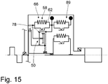
- Fig. 15 a variant embodiment is shown, which essentially on the in Fig. 10 built principle.
- the vibration system 66 here comprises only a single torsional vibration damper 58 whose secondary side 62 is coupled to the ring gear 78 of the coupling arrangement 50.
- a vibration damping arrangement 89 designed here as Festfrequenztilger, so constructed with a deflectable against the return action of one or more springs, but basically free-swinging mass.
- this spring can again different types, such as a fferen réelle- or -zugfeder, for example, constructed of steel material, or elastic material such. As rubber material can be selected.
- the design of the planetary gears, the ring gears or the sun gears may be formed as each rotating about their axes completely rotating wheels, it is nevertheless possible here segment wheels both for the planet gears on the one hand, and the ring gears or On the other hand, use sun gears, wherein the segments are dimensioned such that they have the required Allow relative rotation while maintaining the teeth engagement.
Claims (20)
- Agencement d'embrayage humide, en particulier pour la chaîne cinématique d'un véhicule, comprenant un agencement de boîtier (30) rempli ou pouvant être rempli de fluide, une première formation de surface de friction (106) pouvant tourner avec l'agencement de boîtier (30) autour d'un axe de rotation (A), une deuxième formation de surface de friction (114) pouvant tourner avec un organe de sortie (44) autour de l'axe de rotation (A) et pouvant être amenée en engagement de friction avec la première formation de surface de friction (106), au moins une partie d'un agencement d'amortissement des oscillations de torsion (29) étant prévue dans la voie de transfert de couple entre l'agencement de boîtier (30) et l'organe de sortie (44), ledit agencement d'amortissement comprenant une région d'entrée (52) et une région de sortie (82), entre la région d'entrée (52) et la région de sortie (82) étant prévus une première voie de transfert de couple (46) et, parallèlement à celle-ci, une deuxième voie de transfert de couple (48) ainsi qu'un agencement de couplage (50) pour la superposition des couples transmis par le biais des voies de transfert de couple (46, 48), l'agencement d'amortissement des oscillations de torsion comprenant en outre au moins, dans la première voie de transfert de couple (46), un agencement de déphaseur (56) pour générer un déphasage des irrégularités de rotation transmises par le biais de la première voie de transfert de couple (46) par rapport aux irrégularités de rotation transmises par le biais de la deuxième voie de transfert de couple, caractérisé en ce que l'agencement d'embrayage humide est réalisé de telle sorte que essentiellement aucun couple ne soit transmis par le biais de l'agencement d'embrayage humide si l'engagement par friction entre les formations de surface de friction (106, 114) est supprimé.
- Agencement d'embrayage humide selon la revendication 1, caractérisé en ce que la première formation de surface de friction (106) et la deuxième formation de surface de friction (114) sont prévus dans le flux de couple entre l'agencement de boîtier (30) et l'agencement d'amortissement des oscillations de torsion (29) ou entre l'agencement d'amortissement des oscillations de torsion (29) et l'organe de sortie (44).
- Agencement d'embrayage humide selon la revendication 1, caractérisé en ce que la première formation de surface de friction (106) et la deuxième formation de surface de friction (114) sont prévues dans le flux de couple entre l'agencement de déphaseur (96) et l'agencement de couplage (50).
- Agencement d'embrayage humide selon la revendication 1, caractérisé en ce que la première formation de surface de friction (106) et la deuxième formation de surface de friction (114) sont prévues dans le flux de couple entre l'agencement de boîtier (30) et l'agencement de couplage (50).
- Agencement d'embrayage humide selon l'une quelconque des revendications 1 à 4, caractérisé en ce que chaque formation de surface de friction (106, 114) comprend au moins un élément de friction (108, 112) de type disque annulaire pouvant être pressé en engagement de friction avec un élément de friction de type disque annulaire (108, 112) de l'autre formation de surface de friction (106, 114) par le piston d'embrayage (118).
- Agencement d'embrayage humide selon l'une quelconque des revendications 1 à 5, caractérisé en ce que l'agencement de déphaseur (56) comprend un système oscillant (66) avec un côté primaire (60) et un côté secondaire (62 ; 62') pouvant tourner autour de l'axe de rotation (A) par rapport au côté primaire (60) à l'encontre de l'effet d'un agencement de ressort (64 ; 64, 64').
- Agencement d'embrayage humide selon l'une quelconque des revendications 1 à 6, caractérisé en ce que la région de sortie (82) comprend un système oscillant supplémentaire (90) avec un côté primaire (94) et un côté secondaire (96) pouvant tourner par rapport au côté primaire (94) à l'encontre de l'effet d'un agencement de ressort (98).
- Agencement d'embrayage humide selon l'une quelconque des revendications 1 à 7, caractérisé en ce que l'organe de sortie (44) comprend un moyeu de sortie (44) accouplé ou pouvant être accouplé à un arbre de sortie (20), de préférence un arbre d'entrée de boîte de vitesses (20), en vue de la rotation commune autour de l'axe de rotation (A).
- Agencement d'embrayage humide selon l'une quelconque des revendications 1 à 8, caractérisé en ce que l'agencement de boîtier (30) comprend une formation d'entraînement (36) pour l'entraînement d'une pompe fluidique destinée à refouler du fluide dans l'agencement de boîtier (30).
- Agencement d'embrayage humide selon l'une quelconque des revendications 1 à 9, caractérisé en ce que l'agencement de couplage (50) comprend un agencement de transmission planétaire (68).
- Agencement d'embrayage humide selon la revendication 10, caractérisé en ce que l'agencement d'engrenage planétaire (68) comprend un porte-satellites (70) relié à la deuxième voie de transfert de couple (48), avec une pluralité de satellites (72) supportés à rotation sur celui-ci.
- Agencement d'embrayage humide selon la revendication 11, caractérisé en ce que l'agencement d'engrenage planétaire (68) comprend un premier agencement de roue de couplage (78 ; 78') relié à la première voie de transfert de couple (46) en engagement d'engrènement avec les satellites (72) et un deuxième agencement de roue de couplage (80 ; 80') relié à la région de sortie (82) en engagement d'engrènement avec les satellites (72).
- Agencement d'embrayage humide selon la revendication 12, caractérisé en ce que le premier agencement de roue de couplage (78 ; 78') en liaison avec les satellites (72) et le deuxième agencement de roue de couplage (80 ; 80') en liaison avec les satellites (72) fournissent des rapports de démultiplication différents l'un de l'autre.
- Agencement d'embrayage humide selon l'une quelconque des revendications 12 à 13, caractérisé en ce que le premier agencement de roue de couplage (78) et le deuxième agencement de roue de couplage (80) comprennent chacun un agencement de couronne dentée (78, 80).
- Agencement d'embrayage humide selon l'une quelconque des revendications 12 à 13, caractérisé en ce que le premier agencement de roue de couplage (78') et le deuxième agencement de roue de couplage (80') comprennent chacun un agencement de roue solaire (78, 80').
- Agencement d'embrayage humide selon l'une quelconque des revendications 1 à 15, caractérisé en ce qu'un système oscillant (66) et/ou un système oscillant supplémentaire (90) comprennent au moins deux amortisseurs d'oscillations disposés en série l'un par rapport à l'autre (58, 58') à chaque fois avec un côté primaire (60, 60') et un côté secondaire (62, 62') pouvant tourner par rapport à celui-ci.
- Agencement d'embrayage humide selon l'une quelconque des revendications 1 à 16, caractérisé en ce que le système oscillant (66) et/ou le système oscillant supplémentaire (90) comprennent au moins deux amortisseurs d'oscillations agissant parallèlement l'un à l'autre à chaque fois avec un côté primaire et un côté secondaire pouvant tourner par rapport à celui-ci.
- Agencement d'embrayage humide selon l'une quelconque des revendications 1 à 17, caractérisé en ce que le système oscillant (66) et/ou le système oscillant supplémentaire (90) comprennent un agencement d'amortissement des oscillations à vitesse de rotation adaptative (89, 89') avec au moins une masse de déviation pouvant être déviée dans la direction périphérique à partir d'une position de base et variant ainsi sa distance à l'axe de rotation (A).
- Agencement d'embrayage humide selon l'une quelconque des revendications 1 à 18, caractérisé en ce que le système oscillant (66) et/ou le système oscillant supplémentaire (90) comprennent un agencement d'amortissement des oscillations à fréquence fixe (89, 89') avec au moins une masse oscillante (114) pouvant être déviée à l'encontre de l'action d'un agencement de ressort de rappel (116).
- Agencement d'embrayage humide selon l'une quelconque des revendications 1 à 19, caractérisé en ce qu'un agencement d'amortissement de friction (85, 85', 99) agissant à l'encontre d'une rotation relative entre le côté primaire (60, 94) et le côté secondaire (62, 96 ; 62') de celui-ci est associé au système oscillant (66) et/ou au système oscillant supplémentaire (90).
Applications Claiming Priority (2)
| Application Number | Priority Date | Filing Date | Title |
|---|---|---|---|
| DE102010029255 | 2010-05-25 | ||
| PCT/EP2011/053189 WO2011147598A1 (fr) | 2010-05-25 | 2011-03-03 | Ensemble embrayage hydrodynamique |
Publications (2)
| Publication Number | Publication Date |
|---|---|
| EP2577106A1 EP2577106A1 (fr) | 2013-04-10 |
| EP2577106B1 true EP2577106B1 (fr) | 2017-08-09 |
Family
ID=43530148
Family Applications (7)
| Application Number | Title | Priority Date | Filing Date |
|---|---|---|---|
| EP10790534.1A Active EP2577105B1 (fr) | 2010-05-25 | 2010-12-03 | Appareil hydrodynamique de couplage en particulier un convertisseur de couple |
| EP10787422.4A Active EP2577103B1 (fr) | 2010-05-25 | 2010-12-03 | Appareil hydrodynamique de couplage, en particulier convertisseur de couple. |
| EP10788306.8A Active EP2577104B1 (fr) | 2010-05-25 | 2010-12-03 | Appareil hydrodynamique de couplage |
| EP13188109.6A Active EP2703687B1 (fr) | 2010-05-25 | 2011-03-03 | Module d'entraînement hybride |
| EP11709050.6A Active EP2577107B1 (fr) | 2010-05-25 | 2011-03-03 | Appareil hydrodynamique de couplage |
| EP11706257.0A Active EP2577106B1 (fr) | 2010-05-25 | 2011-03-03 | Appareil hydrodynamique de couplage |
| EP11713296.9A Not-in-force EP2577108B1 (fr) | 2010-05-25 | 2011-04-11 | Appareil hydrodynamique de couplage |
Family Applications Before (5)
| Application Number | Title | Priority Date | Filing Date |
|---|---|---|---|
| EP10790534.1A Active EP2577105B1 (fr) | 2010-05-25 | 2010-12-03 | Appareil hydrodynamique de couplage en particulier un convertisseur de couple |
| EP10787422.4A Active EP2577103B1 (fr) | 2010-05-25 | 2010-12-03 | Appareil hydrodynamique de couplage, en particulier convertisseur de couple. |
| EP10788306.8A Active EP2577104B1 (fr) | 2010-05-25 | 2010-12-03 | Appareil hydrodynamique de couplage |
| EP13188109.6A Active EP2703687B1 (fr) | 2010-05-25 | 2011-03-03 | Module d'entraînement hybride |
| EP11709050.6A Active EP2577107B1 (fr) | 2010-05-25 | 2011-03-03 | Appareil hydrodynamique de couplage |
Family Applications After (1)
| Application Number | Title | Priority Date | Filing Date |
|---|---|---|---|
| EP11713296.9A Not-in-force EP2577108B1 (fr) | 2010-05-25 | 2011-04-11 | Appareil hydrodynamique de couplage |
Country Status (5)
| Country | Link |
|---|---|
| US (6) | US9303744B2 (fr) |
| EP (7) | EP2577105B1 (fr) |
| CN (6) | CN102906458B (fr) |
| DE (1) | DE102011007118A1 (fr) |
| WO (6) | WO2011147488A1 (fr) |
Families Citing this family (116)
| Publication number | Priority date | Publication date | Assignee | Title |
|---|---|---|---|---|
| DE112009005514C5 (de) | 2008-10-17 | 2022-02-17 | Schaeffler Technologies AG & Co. KG | Zweiweg-Torsionsdämpfer |
| CN102906458B (zh) * | 2010-05-25 | 2016-06-08 | Zf腓特烈斯哈芬股份公司 | 扭转振动减振装置 |
| DE102011007117A1 (de) * | 2011-04-11 | 2012-10-11 | Zf Friedrichshafen Ag | Getriebe, insbesondere für den Antriebsstrang eines Fahrzeugs |
| DE102011017655A1 (de) * | 2011-04-28 | 2012-10-31 | Zf Friedrichshafen Ag | Reibungskupplung, insbesondere nasslaufende Reibungskupplung |
| DE102011017652B4 (de) | 2011-04-28 | 2022-03-24 | Zf Friedrichshafen Ag | Hydrodynamische Kopplungsanordnung, insbesondere hydrodynamischer Drehmomentwandler |
| DE102011077119A1 (de) * | 2011-06-07 | 2012-12-13 | Zf Friedrichshafen Ag | Antriebssystem für ein Fahrzeug |
| DE102011084742A1 (de) | 2011-10-19 | 2013-04-25 | Zf Friedrichshafen Ag | Drehschwingungsdämpfungsanordnung, insbesondere für den Antriebsstrang eines Fahrzeugs |
| DE102011086982A1 (de) | 2011-11-23 | 2013-05-23 | Zf Friedrichshafen Ag | Drehschwingungsdämpfungsanordnung, insbesondere für den Antriebsstrang eines Fahrzeugs |
| KR101339234B1 (ko) * | 2011-12-09 | 2013-12-09 | 현대자동차 주식회사 | 댐퍼 클러치 제어 방법 |
| DE102012207862A1 (de) * | 2012-05-11 | 2013-11-14 | Zf Friedrichshafen Ag | Drehschwingungsdämpfungsanordnung, insbesondere für den Antriebsstrang eines Fahrzeugs |
| DE102012212591A1 (de) | 2012-07-18 | 2014-01-23 | Zf Friedrichshafen Ag | Drehschwingungsdämpfungsanordnung, insbesondere für den Antriebsstrang eines Fahrzeugs |
| DE102012212593A1 (de) * | 2012-07-18 | 2014-01-23 | Zf Friedrichshafen Ag | Drehschwingungsdämpfungsanordnung für den Antriebsstrang eines Fahrzeugs |
| WO2014012545A1 (fr) | 2012-07-20 | 2014-01-23 | Schaeffler Technologies AG & Co. KG | Dispositif de transmission de couple |
| DE102012214455A1 (de) | 2012-08-14 | 2014-02-20 | Zf Friedrichshafen Ag | Drehschwingungsdämpfungsanordnung für den Antriebsstrang eines Fahrzeugs |
| DE102012214571A1 (de) | 2012-08-16 | 2014-02-20 | Zf Friedrichshafen Ag | Drehschwingungsdämpfungsanordnung für den Antriebsstrang eines Fahrzeugs |
| DE102012218729A1 (de) * | 2012-10-15 | 2014-04-17 | Zf Friedrichshafen Ag | Drehschwingungsdämpfungsanordnung für den Antriebsstrang eines Fahrzeugs |
| DE102012219421A1 (de) * | 2012-10-24 | 2014-04-24 | Zf Friedrichshafen Ag | Torsionsschwingungsdämpfungsanordnung mit Leistungsverzweigung |
| DE102012219728A1 (de) * | 2012-10-29 | 2014-04-30 | Zf Friedrichshafen Ag | Hybridantriebsmodul und Antriebsstrang |
| EP2743542A3 (fr) * | 2012-12-14 | 2018-01-10 | Schaeffler Technologies AG & Co. KG | Systèmes d'accouplement |
| DE102013220483A1 (de) * | 2012-12-17 | 2014-06-18 | Zf Friedrichshafen Ag | Drehschwingungsdämpfungsanordnung und Verfahren zur Drehschwingungsdämpfung |
| DE102013201621A1 (de) | 2013-01-31 | 2014-07-31 | Zf Friedrichshafen Ag | Drehschwingungsdämpfungsanordnung für den Antriebsstrang eines Fahrzeugs |
| DE102013201617A1 (de) * | 2013-01-31 | 2014-07-31 | Zf Friedrichshafen Ag | Drehschwingungsdämpfungsanordnung für den Antriebsstrang eines Fahrzeugs |
| DE102013201619A1 (de) * | 2013-01-31 | 2014-07-31 | Zf Friedrichshafen Ag | Drehschwingungsdämpfungsanordnung für den Antriebsstrang eines Fahrzeugs |
| JP5792216B2 (ja) * | 2013-03-13 | 2015-10-07 | 富士重工業株式会社 | ダンパ装置 |
| US9163696B2 (en) * | 2013-03-13 | 2015-10-20 | Fuji Jukogyo Kabushiki Kaisha | Damper device |
| US9234562B2 (en) * | 2013-03-13 | 2016-01-12 | Fuji Jukogyo Kabushiki Kaisha | Damper device |
| KR101518892B1 (ko) * | 2013-04-08 | 2015-05-11 | 현대자동차 주식회사 | 차량용 토크 컨버터 |
| DE102014204952A1 (de) | 2013-04-25 | 2014-10-30 | Schaeffler Technologies Gmbh & Co. Kg | Drehschwingungsdämpferanordnung zum Dämpfen von Drehschwingungen einer Antriebswelle eines Kraftfahrzeugmotors |
| DE102013214353A1 (de) * | 2013-07-23 | 2015-01-29 | Zf Friedrichshafen Ag | Anfahrelement für ein Kraftfahrzeug |
| DE102013214352A1 (de) * | 2013-07-23 | 2015-01-29 | Zf Friedrichshafen Ag | Drehschwingungsdämpfungsanordnung für den Antriebsstrang eines Kraftfahrzeugs |
| DE102013214351A1 (de) | 2013-07-23 | 2015-01-29 | Zf Friedrichshafen Ag | Planetengetriebe |
| DE102013214350A1 (de) | 2013-07-23 | 2015-01-29 | Zf Friedrichshafen Ag | Anfahrelement |
| CN105408663B (zh) * | 2013-07-26 | 2019-01-01 | 舍弗勒技术股份两合公司 | 涡轮-扭振减振器以及转换器和扭矩传递装置 |
| DE102013215726A1 (de) | 2013-08-09 | 2015-02-12 | Zf Friedrichshafen Ag | Drehschwingungsdämpfungsanordnung für den Antriebsstrang eines Fahrzeugs |
| DE112014004158T5 (de) * | 2013-09-11 | 2016-06-16 | Schaeffler Technologies AG & Co. KG | Drehmomentwandler mit Leistungsaufteilung |
| DE102013015702B3 (de) | 2013-09-20 | 2014-12-24 | Audi Ag | Rotationsdämpfer für ein Kraftfahrzeug |
| DE102013219033A1 (de) * | 2013-09-23 | 2015-03-26 | Zf Friedrichshafen Ag | Drehschwingungsdämpferanordnung in einem Antriebsstrang eines Fahrzeugs |
| US10099780B2 (en) * | 2013-10-07 | 2018-10-16 | Sikorsky Aircraft Corporation | Active vibration control actuator |
| DE102013221238A1 (de) | 2013-10-21 | 2015-04-23 | Zf Friedrichshafen Ag | Lamellen-Kupplungseinrichtung |
| WO2015063430A1 (fr) * | 2013-10-31 | 2015-05-07 | Valeo Embrayages | Mécanisme de filtration des fluctuations de couple d'un organe secondaire |
| DE102013224992A1 (de) | 2013-12-05 | 2015-06-11 | Zf Friedrichshafen Ag | Getriebeanordnung sowie Verfahren zum Betreiben einer Getriebeanordnung |
| DE102014223867A1 (de) | 2013-12-12 | 2015-06-18 | Schaeffler Technologies AG & Co. KG | Schwingungsdämpfer |
| DE102014223872A1 (de) | 2013-12-12 | 2015-06-18 | Schaeffler Technologies AG & Co. KG | Schwingungsdämpfer |
| DE102014223868A1 (de) | 2013-12-12 | 2015-06-18 | Schaeffler Technologies AG & Co. KG | Schwingungsdämpfer |
| DE102013226939A1 (de) * | 2013-12-20 | 2015-06-25 | Zf Friedrichshafen Ag | Drehschwingungsdämpfungsanordnung für den Antriebsstrang eines Fahrzeugs |
| DE102013226941A1 (de) | 2013-12-20 | 2015-06-25 | Zf Friedrichshafen Ag | Drehschwingungsdämpfungsanordnung für den Antriebsstrang eines Fahrzeugs |
| EP2908025B2 (fr) | 2014-02-12 | 2022-07-13 | Schaeffler Technologies AG & Co. KG | Système d'amortissement à puissance dérivée |
| WO2015124156A1 (fr) | 2014-02-19 | 2015-08-27 | Schaeffler Technologies AG & Co. KG | Dispositif de transmission de couple |
| EP2930396A3 (fr) | 2014-02-19 | 2016-01-20 | Schaeffler Technologies GmbH & Co. KG | Dispositif de transmission de couple et système d'entraînement doté d'un tel dispositif de transmission de couple |
| US9644722B2 (en) | 2014-02-20 | 2017-05-09 | GM Global Technology Operations LLC | One mode continuously variable transmission |
| DE102014204907A1 (de) | 2014-03-17 | 2015-09-17 | Zf Friedrichshafen Ag | Drehschwingungsdämpfungsanordnung für den Antriebsstrang eines Fahrzeugs |
| DE112015001610A5 (de) | 2014-04-01 | 2017-01-26 | Schaeffler Technologies AG & Co. KG | Dämpfersystem |
| DE102014207465A1 (de) | 2014-04-17 | 2015-10-22 | Zf Friedrichshafen Ag | Drehschwingungsdämpfungsanordnung |
| DE102014006691A1 (de) | 2014-05-09 | 2015-11-12 | Zf Friedrichshafen Ag | Drehungleichförmigkeitsreduzierung durch Leistungsverzweigung - Kennlinienauslegung |
| DE102014209222A1 (de) | 2014-05-15 | 2015-11-19 | Zf Friedrichshafen Ag | Drehschwingungsdämpfungseinheit für den Antriebsstrang eines Kraftfahrzeugs |
| DE102014211723A1 (de) * | 2014-06-18 | 2015-12-24 | Schaeffler Technologies AG & Co. KG | Kupplungsscheibe mit Fliehkraftpendel |
| CN105450552B (zh) | 2014-07-02 | 2018-12-14 | 阿尔卡特朗讯 | 基于sdn网络对应用服务链的策略与计费控制方法与设备 |
| DE102014212825A1 (de) | 2014-07-02 | 2016-01-07 | Schaeffler Technologies AG & Co. KG | Drehschwingungsdämpfer |
| DE102015207825A1 (de) * | 2014-07-24 | 2016-01-28 | Zf Friedrichshafen Ag | Drehschwingungsdämpfungsanordnung für den Antriebsstrang eines Fahrzeugs |
| DE102014215859A1 (de) * | 2014-08-11 | 2016-02-11 | Zf Friedrichshafen Ag | Montagekonzept für eine Drehschwingungsdämpfungsanordnung für den Antriebsstrang eines Fahrzeugs |
| DE102014216072A1 (de) | 2014-08-13 | 2016-02-18 | Zf Friedrichshafen Ag | Drehschwingungsdämpfungsanordnung für den Antriebsstrang eines Fahrzeugs |
| DE102014217725A1 (de) * | 2014-09-04 | 2016-03-10 | Zf Friedrichshafen Ag | Drehschwingungsdämpfungsanordnung |
| DE102014221107A1 (de) | 2014-10-17 | 2016-04-21 | Zf Friedrichshafen Ag | Drehschwingungsdämpfungsanordnung für den Antriebsstrang eines Fahrzeugs |
| DE102015207828A1 (de) | 2014-12-12 | 2016-06-16 | Zf Friedrichshafen Ag | Drehschwingungsdämpfungsanordnung für einen Antriebsstrang eines Fahrzeugs |
| DE102015208715A1 (de) | 2015-05-11 | 2016-11-17 | Zf Friedrichshafen Ag | Drehschwingungsdämpfungsanordnung für den Antriebsstrang eines Fahrzeugs |
| KR101707804B1 (ko) * | 2015-07-16 | 2017-02-17 | 한국파워트레인 주식회사 | 진자를 이용한 진동저감장치를 포함하는 차량용 토크 컨버터 |
| US9500259B1 (en) * | 2015-08-11 | 2016-11-22 | Gm Global Technology Operations, Llc | High performance torsional vibration isolator |
| WO2017044098A1 (fr) * | 2015-09-10 | 2017-03-16 | Uebel Ryan | Transmission automobile |
| JP6344357B2 (ja) * | 2015-09-30 | 2018-06-20 | マツダ株式会社 | 遠心振子ダンパ付き動力伝達装置 |
| US9822862B2 (en) * | 2015-10-02 | 2017-11-21 | Valeo Embrayages | Hydrokinetic torque coupling device for a motor vehicle |
| DE102015219968A1 (de) | 2015-10-14 | 2017-04-20 | Zf Friedrichshafen Ag | Drehschwingungsdämpfungsanordnung für den Antriebsstrang eines Fahrzeugs |
| DE102015221894A1 (de) * | 2015-11-06 | 2017-05-11 | Zf Friedrichshafen Ag | Drehschwingungsdämpfungsanordnung für den Antriebsstrang eines Fahrzeugs |
| DE102015221893A1 (de) | 2015-11-06 | 2017-05-11 | Zf Friedrichshafen Ag | Drehschwingungsdämpfungsanordnung für den Antriebsstrang eines Fahrzeugs |
| DE102015223604A1 (de) * | 2015-11-27 | 2017-06-01 | Zf Friedrichshafen Ag | Planetenstufenautomatgetriebe mit alternativer Nebenabtriebsanordnung |
| DE102016223768A1 (de) | 2015-12-03 | 2017-06-08 | Schaeffler Technologies AG & Co. KG | Drehschwingungsdämpfer |
| DE102015224339A1 (de) * | 2015-12-04 | 2017-06-08 | Zf Friedrichshafen Ag | Drehschwingungsdämpfungsanordnung für den Antriebsstrang eines Kraftfahrzeugs |
| JP6344373B2 (ja) * | 2015-12-07 | 2018-06-20 | マツダ株式会社 | 遠心振子ダンパ付きパワートレインの制御装置 |
| DE102015224664A1 (de) | 2015-12-09 | 2017-06-14 | Zf Friedrichshafen Ag | Formschlusskupplung mit einem Rückstellelement |
| DE102016200888A1 (de) * | 2016-01-22 | 2017-07-27 | Zf Friedrichshafen Ag | Drehschwingungsdämpfungsanordnung für einen Antriebsstrang eines Fahrzeugs |
| DE102016201870A1 (de) * | 2016-02-08 | 2017-08-10 | Zf Friedrichshafen Ag | Kopplungsanordnung |
| JP6489039B2 (ja) | 2016-02-23 | 2019-03-27 | マツダ株式会社 | 自動変速機 |
| JP6315006B2 (ja) | 2016-02-23 | 2018-04-25 | マツダ株式会社 | 摩擦締結要素及び自動変速機 |
| JP6505035B2 (ja) * | 2016-03-01 | 2019-04-24 | 本田技研工業株式会社 | トルク伝達装置 |
| US10006517B2 (en) * | 2016-03-03 | 2018-06-26 | GM Global Technology Operations LLC | Torsional vibration damper with planetary gear enhanced by inertial mass |
| WO2017158131A2 (fr) | 2016-03-17 | 2017-09-21 | Hasse & Wrede Gmbh | Système bielle-manivelle avec amortisseur de vibrations torsionnelles |
| DE102017104720B4 (de) * | 2016-03-23 | 2018-12-20 | Toyota Jidosha Kabushiki Kaisha | Drehmomentwandler mit Drehschwingungsdämpfungsvorrichtung |
| JP6315015B2 (ja) * | 2016-03-25 | 2018-04-25 | トヨタ自動車株式会社 | 捩り振動低減装置 |
| DE102016211943A1 (de) | 2016-06-30 | 2018-01-04 | Zf Friedrichshafen Ag | Torsionsschwingungsdämpfungssystem für einen Kraftfahrzeugantriebsstrang, Hybridantriebsmodul und Kraftfahrzeugantriebsstrang |
| DE102016211945A1 (de) * | 2016-06-30 | 2018-01-04 | Zf Friedrichshafen Ag | Drehmomentübertragungsvorrichtung |
| DE112017004240T5 (de) * | 2016-08-23 | 2019-06-13 | Schaeffler Technologies AG & Co. KG | Rotorträgerbaugruppe |
| US10119604B2 (en) * | 2016-11-15 | 2018-11-06 | GM Global Technology Operations LLC | Damper architectures |
| DE102016225865A1 (de) | 2016-12-21 | 2018-06-21 | Zf Friedrichshafen Ag | Drehschwingungsdämpfungsanordnung für den Antriebsstrang eines Fahrzeugs |
| DE102017100665A1 (de) | 2017-01-16 | 2018-07-19 | Schaeffler Technologies AG & Co. KG | Drehmomentübertragungseinrichtung |
| DE102017100664A1 (de) | 2017-01-16 | 2018-07-19 | Schaeffler Technologies AG & Co. KG | Drehmomentübertragungseinrichtung |
| DE102017106232A1 (de) | 2017-03-23 | 2018-09-27 | Schaeffler Technologies AG & Co. KG | Drehmomentübertragungseinrichtung |
| DE102017205942A1 (de) * | 2017-04-06 | 2018-10-11 | Bayerische Motoren Werke Aktiengesellschaft | Antriebsvorrichtung mit einer Kupplungseinrichtung, Antriebssystem mit dieser Antriebsvorrichtung und Verfahren zum Betrieb des Antriebsystems |
| DE102017207031A1 (de) | 2017-04-26 | 2018-10-31 | Zf Friedrichshafen Ag | Drehschwingungsdämpfungsanordnung für den Antriebsstrang eines Fahrzeugs |
| DE102017111930A1 (de) | 2017-05-31 | 2018-12-06 | Schaeffler Technologies AG & Co. KG | Drehmomentübertragungseinrichtung |
| US10151373B1 (en) * | 2017-06-09 | 2018-12-11 | GM Global Technology Operations LLC | Planetary damper architecture with centrifugal pendulum absorber |
| DE102017113222A1 (de) * | 2017-06-16 | 2018-12-20 | Schaeffler Technologies AG & Co. KG | Dämpfungssystem für achsparallele Hybridmodule |
| DE102017219476A1 (de) * | 2017-06-20 | 2018-12-20 | Zf Friedrichshafen Ag | Drehmomentübertragungsanordnung |
| JP6870545B2 (ja) | 2017-09-05 | 2021-05-12 | トヨタ自動車株式会社 | ハイブリッド車両 |
| US10753425B2 (en) * | 2017-11-02 | 2020-08-25 | Schaeffler Technologies AG & Co. KG | Internal rotor damper modular hybrid transmission |
| CN111212989B (zh) * | 2017-11-14 | 2021-11-30 | 爱信艾达工业株式会社 | 减振装置 |
| DE112018005972T5 (de) * | 2017-11-22 | 2020-08-06 | Valeo Embrayages | Übertragungsvorrichtung für ein Hybridfahrzeug |
| DE102017128362A1 (de) * | 2017-11-30 | 2019-06-06 | Voith Patent Gmbh | Anfahr- und Retardermodul |
| DE102018106285A1 (de) * | 2018-03-19 | 2019-09-19 | Schaeffler Technologies AG & Co. KG | Hybriddämpferzentrierungslösung für ein Hybridmodul und einen Antriebsstrang |
| DE102018211085A1 (de) | 2018-07-05 | 2020-01-09 | Zf Friedrichshafen Ag | Drehschwingungsdämpfungsanordnung für einen Antriebsstrang eines Fahrzeugs |
| US11448279B2 (en) | 2018-11-01 | 2022-09-20 | Valeo Kapec Co., Ltd. | Damper apparatus for use with vehicle torque converters |
| US10857870B2 (en) * | 2018-12-11 | 2020-12-08 | Ford Global Technologies, Llc | Hybrid vehicle |
| DE102018222306A1 (de) | 2018-12-19 | 2020-06-25 | Zf Friedrichshafen Ag | Drehschwingungsdämpfungsanordnung für den Antriebsstrang eines Fahrzeugs |
| US20220205491A1 (en) * | 2019-05-09 | 2022-06-30 | Aisin Aw Industries Co., Ltd | Damper device |
| US11242920B2 (en) * | 2019-12-04 | 2022-02-08 | GM Global Technology Operations LLC | Torque converter assemblies with integrated planetary-type torsional vibration dampers |
| US11387705B2 (en) * | 2019-12-09 | 2022-07-12 | Dana Tm4 Inc. | Torsional mass tuned damper |
| CN111911613A (zh) * | 2020-08-13 | 2020-11-10 | 浙江盘毂动力科技有限公司 | 用于新能源车辆的柔性传动系统 |
| KR20230102229A (ko) * | 2021-12-30 | 2023-07-07 | 주식회사 카펙발레오 | 다단식 토션 댐퍼를 구비한 진동 감쇠 장치 |
Family Cites Families (49)
| Publication number | Priority date | Publication date | Assignee | Title |
|---|---|---|---|---|
| US4513634A (en) * | 1977-05-13 | 1985-04-30 | Nissan Motor Company, Limited | Change-speed transmission with selective bypass of hydrokinetic unit |
| DE19504209C1 (de) * | 1995-02-09 | 1996-05-30 | Fichtel & Sachs Ag | Torsionsschwingungsdämpfer mit lasteinstellbaren Getriebeelementen |
| DE19700851A1 (de) * | 1996-01-18 | 1997-07-24 | Luk Lamellen & Kupplungsbau | Torsionsschwingungsdämpfer |
| GB2346194B (en) * | 1996-01-18 | 2000-09-13 | Luk Lamellen & Kupplungsbau | Apparatus for damping fluctuations of torque |
| DE19611184C2 (de) * | 1996-03-21 | 1998-04-09 | Mannesmann Sachs Ag | Drehschwingungsdämpfer |
| DE19744528A1 (de) * | 1996-10-09 | 1998-04-30 | Luk Lamellen & Kupplungsbau | Drehmomentübertragungseinrichtung sowie mehrteiliges Schwungrad zur Drehmomentübertragung |
| DE19644173C1 (de) * | 1996-10-24 | 1997-12-18 | Mannesmann Sachs Ag | Torsionsschwingungsdämpfer mit einem Verschluß für Öffnungen zum Befüllen der Fettkammer |
| DE19727678C2 (de) * | 1997-06-30 | 1999-12-16 | Mannesmann Sachs Ag | Torsionsschwingungsdämpfer mit einem Planetengetriebe mit wenigstens einem Verzahnungselement |
| DE19736843C2 (de) * | 1997-08-25 | 2000-08-31 | Mannesmann Sachs Ag | Torsionsschwingungsdämpfer an einer Überbrückungskupplung mit Planetengetriebe |
| DE19747963A1 (de) * | 1997-10-30 | 1999-05-12 | Bayerische Motoren Werke Ag | Drehmomentwandleranbindung mit Schwingungsdämpfer |
| US6244401B1 (en) * | 1998-05-06 | 2001-06-12 | Luk Getriebe-Systeme Gmbh | Force transmitting apparatus |
| US6083133A (en) * | 1998-05-08 | 2000-07-04 | Zexel Torsen Inc. | Bevel gear differential with asymmetrically distributed pinions |
| DE19826351C2 (de) * | 1998-06-12 | 2001-06-28 | Daimler Chrysler Ag | Antriebsanordnung mit hydrodynamischen Drehmomentwandler und zwei Dämpfern |
| DE19835758A1 (de) * | 1998-08-13 | 2000-02-17 | Mannesmann Sachs Ag | Torsionsschwingungsdämpfer mit einer axialen Sicherungseinrichtung |
| DE19846445A1 (de) * | 1998-08-27 | 2000-03-02 | Mannesmann Sachs Ag | Torsionsschwingungsdämpfer an einer Überbrückungskupplung mit Planetengetriebe |
| US6231472B1 (en) * | 1998-08-27 | 2001-05-15 | Mannesmann Sachs Ag | Torsional vibration damper in a lockup clutch with planetary gear set |
| DE19904857A1 (de) * | 1999-02-05 | 2000-08-10 | Mannesmann Sachs Ag | Hydrodynamischer Drehmomentwandler |
| DE19904850B4 (de) * | 1999-02-05 | 2007-07-12 | Zf Sachs Ag | Torsionsschwingungsdämpfer |
| DE19923316A1 (de) * | 1999-05-21 | 2000-11-23 | Zahnradfabrik Friedrichshafen | Antriebssystem für ein Kraftfahrzeug |
| DE19943038A1 (de) * | 1999-09-09 | 2001-03-15 | Mannesmann Sachs Ag | Antriebssystem |
| US6487855B1 (en) * | 1999-11-11 | 2002-12-03 | Yutaka Giken Co., Ltd. | Torque converter |
| DE10128424A1 (de) * | 2001-06-12 | 2002-12-19 | Zf Sachs Ag | Antriebssystem |
| DE10152808B4 (de) * | 2001-10-25 | 2016-03-17 | Daimler Ag | Antriebsstrang für Kraftfahrzeuge |
| FR2843433B1 (fr) * | 2002-08-06 | 2005-04-01 | Valeo Embrayages | Appareil d'accouplement hydrocinetique, notamment pour un vehicule automobile |
| US7077253B2 (en) * | 2002-11-16 | 2006-07-18 | Luk Lamellen Und Kupplungsbau Beteiligungs Kg | Torque converter |
| DE10350935B4 (de) * | 2002-11-16 | 2019-02-21 | Schaeffler Technologies AG & Co. KG | Drehmomentwandler |
| JP2004308904A (ja) * | 2003-04-05 | 2004-11-04 | Zf Sachs Ag | 捩り振動ダンパ |
| DE10357292B4 (de) * | 2003-12-05 | 2006-02-02 | Voith Turbo Gmbh & Co. Kg | Verfahren für die Steuerung eines Antriebsstrangs für eine Strömungskraftmaschine mit Drehzahlführung, Kraftstoßreduktion und Kurzzeitenergiespeicherung |
| JP4568496B2 (ja) * | 2003-12-18 | 2010-10-27 | 富士重工業株式会社 | トルクコンバータ |
| DE502005003692D1 (de) * | 2004-02-18 | 2008-05-29 | Luk Lamellen & Kupplungsbau | Torsionsschwingungsdämpfer |
| DE102004024004B4 (de) * | 2004-05-14 | 2017-01-26 | Daimler Ag | Hydrodynamischer Drehmomentwandler |
| DE102004048754A1 (de) * | 2004-10-05 | 2006-04-13 | Voith Turbo Gmbh & Co. Kg | Pod-Schiffsantrieb mit Getriebe |
| WO2007017935A1 (fr) * | 2005-08-10 | 2007-02-15 | Nobuyoshi Sugitani | Dispositif d’engrenage planétaire |
| DE112006003626A5 (de) * | 2006-01-12 | 2008-10-02 | Luk Lamellen Und Kupplungsbau Beteiligungs Kg | Drehmomentwandler mit Überbrückungskupplung zwischen zwei Dämpfern |
| US20080119316A1 (en) * | 2006-11-17 | 2008-05-22 | Ordo James P | Apparatus for expanding gear speed ratio coverage of an automatic transmission |
| KR101491194B1 (ko) * | 2007-08-02 | 2015-02-06 | 섀플러 테크놀로지스 게엠베하 운트 코. 카게 | 진동 감쇠 장치, 특히 다단식 비틀림 진동 댐퍼 |
| US8135525B2 (en) * | 2007-11-14 | 2012-03-13 | Schaeffler Technologies AG & Co. KG | Torque converter with turbine mass absorber |
| CN101883933B (zh) * | 2007-11-29 | 2014-04-23 | 舍弗勒技术股份两合公司 | 尤其是用于在驱动机与从动部分之间传递功率的力传递装置 |
| WO2010022697A1 (fr) * | 2008-09-01 | 2010-03-04 | Luk Lamellen Und Kupplungsbau Beteiligungs Kg | Volant moteur bi-masse |
| KR101145625B1 (ko) * | 2009-11-23 | 2012-06-28 | 현대자동차주식회사 | 토크 분기형 자동변속기 |
| KR101145624B1 (ko) * | 2009-11-23 | 2012-05-15 | 현대자동차주식회사 | 토크 분기형 자동변속기 |
| KR101509677B1 (ko) * | 2009-11-23 | 2015-04-08 | 현대자동차 주식회사 | 토크 분기형 자동변속기 |
| CN102906458B (zh) * | 2010-05-25 | 2016-06-08 | Zf腓特烈斯哈芬股份公司 | 扭转振动减振装置 |
| DE102011007117A1 (de) * | 2011-04-11 | 2012-10-11 | Zf Friedrichshafen Ag | Getriebe, insbesondere für den Antriebsstrang eines Fahrzeugs |
| DE102011077119A1 (de) * | 2011-06-07 | 2012-12-13 | Zf Friedrichshafen Ag | Antriebssystem für ein Fahrzeug |
| DE102012218729A1 (de) * | 2012-10-15 | 2014-04-17 | Zf Friedrichshafen Ag | Drehschwingungsdämpfungsanordnung für den Antriebsstrang eines Fahrzeugs |
| US8939859B2 (en) * | 2012-10-19 | 2015-01-27 | Caterpillar Inc. | Torque converter with stator clutch |
| US8608604B1 (en) * | 2012-10-19 | 2013-12-17 | Caterpillar Inc. | Torque divider and torque converter with lockup clutch |
| US9234562B2 (en) * | 2013-03-13 | 2016-01-12 | Fuji Jukogyo Kabushiki Kaisha | Damper device |
-
2010
- 2010-12-03 CN CN201080067021.5A patent/CN102906458B/zh not_active Expired - Fee Related
- 2010-12-03 EP EP10790534.1A patent/EP2577105B1/fr active Active
- 2010-12-03 US US13/699,945 patent/US9303744B2/en active Active
- 2010-12-03 US US13/699,968 patent/US9316299B2/en active Active
- 2010-12-03 CN CN201080067024.9A patent/CN102906460B/zh not_active Expired - Fee Related
- 2010-12-03 WO PCT/EP2010/068823 patent/WO2011147488A1/fr active Application Filing
- 2010-12-03 US US13/699,812 patent/US8939860B2/en not_active Expired - Fee Related
- 2010-12-03 CN CN201080067023.4A patent/CN102906459B/zh not_active Expired - Fee Related
- 2010-12-03 EP EP10787422.4A patent/EP2577103B1/fr active Active
- 2010-12-03 WO PCT/EP2010/068822 patent/WO2011147487A1/fr active Application Filing
- 2010-12-03 EP EP10788306.8A patent/EP2577104B1/fr active Active
- 2010-12-03 WO PCT/EP2010/068821 patent/WO2011147486A1/fr active Application Filing
-
2011
- 2011-03-03 EP EP13188109.6A patent/EP2703687B1/fr active Active
- 2011-03-03 CN CN201180025802.2A patent/CN102918302B/zh active Active
- 2011-03-03 US US13/699,853 patent/US9151373B2/en not_active Expired - Fee Related
- 2011-03-03 EP EP11709050.6A patent/EP2577107B1/fr active Active
- 2011-03-03 EP EP11706257.0A patent/EP2577106B1/fr active Active
- 2011-03-03 WO PCT/EP2011/053187 patent/WO2011147597A1/fr active Application Filing
- 2011-03-03 CN CN201180025803.7A patent/CN102918303B/zh active Active
- 2011-03-03 WO PCT/EP2011/053189 patent/WO2011147598A1/fr active Application Filing
- 2011-03-03 US US13/700,055 patent/US8991531B2/en not_active Expired - Fee Related
- 2011-04-11 DE DE102011007118A patent/DE102011007118A1/de not_active Ceased
- 2011-04-11 CN CN201180025793.7A patent/CN102959282B/zh not_active Expired - Fee Related
- 2011-04-11 EP EP11713296.9A patent/EP2577108B1/fr not_active Not-in-force
- 2011-04-11 WO PCT/EP2011/055601 patent/WO2011147633A1/fr active Application Filing
- 2011-04-11 US US13/699,913 patent/US9416857B2/en active Active
Non-Patent Citations (1)
| Title |
|---|
| None * |
Also Published As
Similar Documents
| Publication | Publication Date | Title |
|---|---|---|
| EP2577106B1 (fr) | Appareil hydrodynamique de couplage | |
| DE102011075241A1 (de) | Nasslaufende Kupplungsanordnung | |
| DE102011075242A1 (de) | Drehschwingungsdämpfungsanordnung | |
| DE102011075244A1 (de) | Hydrodynamische Kopplungseinrichtung, insbesondere Drehmomentwandler | |
| EP2702296B1 (fr) | Ensemble de transmission de couple de rotation | |
| EP2697536B1 (fr) | Boîte de vitesses, en particulier pour la chaîne cinématique d'un véhicule | |
| DE102011075243A1 (de) | Hydrodynamische Kopplungseinrichtung, insbesondere Drehmomentwandler | |
| EP2836737A1 (fr) | Ensemble d'amortissement des vibrations torsionnelles | |
| DE102007057431B4 (de) | Hydrodynamische Kopplungseinrichtung | |
| EP2697535A1 (fr) | Ensemble d'amortissement des vibrations torsionnelles, en particulier pour une chaîne cinématique d'un véhicule | |
| DE102011075240A1 (de) | Hybridantriebsmodul | |
| DE102012217171B4 (de) | Hydrodynamische Kopplungsanordnung, insbesondere Drehmomentwandler | |
| WO2017028858A1 (fr) | Pendule à force centrifuge et convertisseur de couple hydrodynamique équipé d'un pendule à force centrifuge | |
| DE19846445A1 (de) | Torsionsschwingungsdämpfer an einer Überbrückungskupplung mit Planetengetriebe | |
| WO2018145820A1 (fr) | Arrangement de transmission de couple | |
| EP2882979B1 (fr) | Ensemble amortisseur de vibrations de torsion à dérivation de puissance | |
| DE102012205794A1 (de) | Antriebsstrang für ein Mehrachsfahrzeug | |
| DE102007057432B4 (de) | Hydrodynamische Kopplungseinrichtung | |
| DE102011017657A1 (de) | Drehmomentübertragungsanordnung für den Antriebsstrang eines Fahrzeugs | |
| DE102011017650B4 (de) | Hydrodynamische Kopplungsanordnung |
Legal Events
| Date | Code | Title | Description |
|---|---|---|---|
| PUAI | Public reference made under article 153(3) epc to a published international application that has entered the european phase |
Free format text: ORIGINAL CODE: 0009012 |
|
| 17P | Request for examination filed |
Effective date: 20121029 |
|
| AK | Designated contracting states |
Kind code of ref document: A1 Designated state(s): AL AT BE BG CH CY CZ DE DK EE ES FI FR GB GR HR HU IE IS IT LI LT LU LV MC MK MT NL NO PL PT RO RS SE SI SK SM TR |
|
| DAX | Request for extension of the european patent (deleted) | ||
| GRAP | Despatch of communication of intention to grant a patent |
Free format text: ORIGINAL CODE: EPIDOSNIGR1 |
|
| INTG | Intention to grant announced |
Effective date: 20170328 |
|
| GRAS | Grant fee paid |
Free format text: ORIGINAL CODE: EPIDOSNIGR3 |
|
| GRAA | (expected) grant |
Free format text: ORIGINAL CODE: 0009210 |
|
| AK | Designated contracting states |
Kind code of ref document: B1 Designated state(s): AL AT BE BG CH CY CZ DE DK EE ES FI FR GB GR HR HU IE IS IT LI LT LU LV MC MK MT NL NO PL PT RO RS SE SI SK SM TR |
|
| REG | Reference to a national code |
Ref country code: GB Ref legal event code: FG4D Free format text: NOT ENGLISH |
|
| REG | Reference to a national code |
Ref country code: CH Ref legal event code: EP Ref country code: AT Ref legal event code: REF Ref document number: 917211 Country of ref document: AT Kind code of ref document: T Effective date: 20170815 |
|
| REG | Reference to a national code |
Ref country code: IE Ref legal event code: FG4D Free format text: LANGUAGE OF EP DOCUMENT: GERMAN |
|
| REG | Reference to a national code |
Ref country code: DE Ref legal event code: R096 Ref document number: 502011012766 Country of ref document: DE |
|
| REG | Reference to a national code |
Ref country code: NL Ref legal event code: MP Effective date: 20170809 |
|
| REG | Reference to a national code |
Ref country code: LT Ref legal event code: MG4D |
|
| REG | Reference to a national code |
Ref country code: FR Ref legal event code: PLFP Year of fee payment: 8 |
|
| PG25 | Lapsed in a contracting state [announced via postgrant information from national office to epo] |
Ref country code: NO Free format text: LAPSE BECAUSE OF FAILURE TO SUBMIT A TRANSLATION OF THE DESCRIPTION OR TO PAY THE FEE WITHIN THE PRESCRIBED TIME-LIMIT Effective date: 20171109 Ref country code: SE Free format text: LAPSE BECAUSE OF FAILURE TO SUBMIT A TRANSLATION OF THE DESCRIPTION OR TO PAY THE FEE WITHIN THE PRESCRIBED TIME-LIMIT Effective date: 20170809 Ref country code: LT Free format text: LAPSE BECAUSE OF FAILURE TO SUBMIT A TRANSLATION OF THE DESCRIPTION OR TO PAY THE FEE WITHIN THE PRESCRIBED TIME-LIMIT Effective date: 20170809 Ref country code: FI Free format text: LAPSE BECAUSE OF FAILURE TO SUBMIT A TRANSLATION OF THE DESCRIPTION OR TO PAY THE FEE WITHIN THE PRESCRIBED TIME-LIMIT Effective date: 20170809 Ref country code: HR Free format text: LAPSE BECAUSE OF FAILURE TO SUBMIT A TRANSLATION OF THE DESCRIPTION OR TO PAY THE FEE WITHIN THE PRESCRIBED TIME-LIMIT Effective date: 20170809 Ref country code: NL Free format text: LAPSE BECAUSE OF FAILURE TO SUBMIT A TRANSLATION OF THE DESCRIPTION OR TO PAY THE FEE WITHIN THE PRESCRIBED TIME-LIMIT Effective date: 20170809 |
|
| PG25 | Lapsed in a contracting state [announced via postgrant information from national office to epo] |
Ref country code: PL Free format text: LAPSE BECAUSE OF FAILURE TO SUBMIT A TRANSLATION OF THE DESCRIPTION OR TO PAY THE FEE WITHIN THE PRESCRIBED TIME-LIMIT Effective date: 20170809 Ref country code: GR Free format text: LAPSE BECAUSE OF FAILURE TO SUBMIT A TRANSLATION OF THE DESCRIPTION OR TO PAY THE FEE WITHIN THE PRESCRIBED TIME-LIMIT Effective date: 20171110 Ref country code: LV Free format text: LAPSE BECAUSE OF FAILURE TO SUBMIT A TRANSLATION OF THE DESCRIPTION OR TO PAY THE FEE WITHIN THE PRESCRIBED TIME-LIMIT Effective date: 20170809 Ref country code: IS Free format text: LAPSE BECAUSE OF FAILURE TO SUBMIT A TRANSLATION OF THE DESCRIPTION OR TO PAY THE FEE WITHIN THE PRESCRIBED TIME-LIMIT Effective date: 20171209 Ref country code: ES Free format text: LAPSE BECAUSE OF FAILURE TO SUBMIT A TRANSLATION OF THE DESCRIPTION OR TO PAY THE FEE WITHIN THE PRESCRIBED TIME-LIMIT Effective date: 20170809 Ref country code: BG Free format text: LAPSE BECAUSE OF FAILURE TO SUBMIT A TRANSLATION OF THE DESCRIPTION OR TO PAY THE FEE WITHIN THE PRESCRIBED TIME-LIMIT Effective date: 20171109 Ref country code: RS Free format text: LAPSE BECAUSE OF FAILURE TO SUBMIT A TRANSLATION OF THE DESCRIPTION OR TO PAY THE FEE WITHIN THE PRESCRIBED TIME-LIMIT Effective date: 20170809 |
|
| PG25 | Lapsed in a contracting state [announced via postgrant information from national office to epo] |
Ref country code: DK Free format text: LAPSE BECAUSE OF FAILURE TO SUBMIT A TRANSLATION OF THE DESCRIPTION OR TO PAY THE FEE WITHIN THE PRESCRIBED TIME-LIMIT Effective date: 20170809 Ref country code: RO Free format text: LAPSE BECAUSE OF FAILURE TO SUBMIT A TRANSLATION OF THE DESCRIPTION OR TO PAY THE FEE WITHIN THE PRESCRIBED TIME-LIMIT Effective date: 20170809 Ref country code: CZ Free format text: LAPSE BECAUSE OF FAILURE TO SUBMIT A TRANSLATION OF THE DESCRIPTION OR TO PAY THE FEE WITHIN THE PRESCRIBED TIME-LIMIT Effective date: 20170809 |
|
| REG | Reference to a national code |
Ref country code: DE Ref legal event code: R097 Ref document number: 502011012766 Country of ref document: DE |
|
| PG25 | Lapsed in a contracting state [announced via postgrant information from national office to epo] |
Ref country code: EE Free format text: LAPSE BECAUSE OF FAILURE TO SUBMIT A TRANSLATION OF THE DESCRIPTION OR TO PAY THE FEE WITHIN THE PRESCRIBED TIME-LIMIT Effective date: 20170809 Ref country code: IT Free format text: LAPSE BECAUSE OF FAILURE TO SUBMIT A TRANSLATION OF THE DESCRIPTION OR TO PAY THE FEE WITHIN THE PRESCRIBED TIME-LIMIT Effective date: 20170809 Ref country code: SK Free format text: LAPSE BECAUSE OF FAILURE TO SUBMIT A TRANSLATION OF THE DESCRIPTION OR TO PAY THE FEE WITHIN THE PRESCRIBED TIME-LIMIT Effective date: 20170809 Ref country code: SM Free format text: LAPSE BECAUSE OF FAILURE TO SUBMIT A TRANSLATION OF THE DESCRIPTION OR TO PAY THE FEE WITHIN THE PRESCRIBED TIME-LIMIT Effective date: 20170809 |
|
| PLBE | No opposition filed within time limit |
Free format text: ORIGINAL CODE: 0009261 |
|
| STAA | Information on the status of an ep patent application or granted ep patent |
Free format text: STATUS: NO OPPOSITION FILED WITHIN TIME LIMIT |
|
| 26N | No opposition filed |
Effective date: 20180511 |
|
| PG25 | Lapsed in a contracting state [announced via postgrant information from national office to epo] |
Ref country code: SI Free format text: LAPSE BECAUSE OF FAILURE TO SUBMIT A TRANSLATION OF THE DESCRIPTION OR TO PAY THE FEE WITHIN THE PRESCRIBED TIME-LIMIT Effective date: 20170809 |
|
| PG25 | Lapsed in a contracting state [announced via postgrant information from national office to epo] |
Ref country code: MT Free format text: LAPSE BECAUSE OF FAILURE TO SUBMIT A TRANSLATION OF THE DESCRIPTION OR TO PAY THE FEE WITHIN THE PRESCRIBED TIME-LIMIT Effective date: 20170809 |
|
| REG | Reference to a national code |
Ref country code: CH Ref legal event code: PL |
|
| GBPC | Gb: european patent ceased through non-payment of renewal fee |
Effective date: 20180303 |
|
| PG25 | Lapsed in a contracting state [announced via postgrant information from national office to epo] |
Ref country code: MC Free format text: LAPSE BECAUSE OF FAILURE TO SUBMIT A TRANSLATION OF THE DESCRIPTION OR TO PAY THE FEE WITHIN THE PRESCRIBED TIME-LIMIT Effective date: 20170809 |
|
| REG | Reference to a national code |
Ref country code: BE Ref legal event code: MM Effective date: 20180331 |
|
| REG | Reference to a national code |
Ref country code: IE Ref legal event code: MM4A |
|
| PG25 | Lapsed in a contracting state [announced via postgrant information from national office to epo] |
Ref country code: LU Free format text: LAPSE BECAUSE OF NON-PAYMENT OF DUE FEES Effective date: 20180303 |
|
| PG25 | Lapsed in a contracting state [announced via postgrant information from national office to epo] |
Ref country code: IE Free format text: LAPSE BECAUSE OF NON-PAYMENT OF DUE FEES Effective date: 20180303 |
|
| PG25 | Lapsed in a contracting state [announced via postgrant information from national office to epo] |
Ref country code: BE Free format text: LAPSE BECAUSE OF NON-PAYMENT OF DUE FEES Effective date: 20180331 Ref country code: LI Free format text: LAPSE BECAUSE OF NON-PAYMENT OF DUE FEES Effective date: 20180331 Ref country code: CH Free format text: LAPSE BECAUSE OF NON-PAYMENT OF DUE FEES Effective date: 20180331 Ref country code: GB Free format text: LAPSE BECAUSE OF NON-PAYMENT OF DUE FEES Effective date: 20180303 |
|
| REG | Reference to a national code |
Ref country code: AT Ref legal event code: MM01 Ref document number: 917211 Country of ref document: AT Kind code of ref document: T Effective date: 20180303 |
|
| PG25 | Lapsed in a contracting state [announced via postgrant information from national office to epo] |
Ref country code: AT Free format text: LAPSE BECAUSE OF NON-PAYMENT OF DUE FEES Effective date: 20180303 |
|
| PG25 | Lapsed in a contracting state [announced via postgrant information from national office to epo] |
Ref country code: TR Free format text: LAPSE BECAUSE OF FAILURE TO SUBMIT A TRANSLATION OF THE DESCRIPTION OR TO PAY THE FEE WITHIN THE PRESCRIBED TIME-LIMIT Effective date: 20170809 |
|
| PG25 | Lapsed in a contracting state [announced via postgrant information from national office to epo] |
Ref country code: HU Free format text: LAPSE BECAUSE OF FAILURE TO SUBMIT A TRANSLATION OF THE DESCRIPTION OR TO PAY THE FEE WITHIN THE PRESCRIBED TIME-LIMIT; INVALID AB INITIO Effective date: 20110303 Ref country code: PT Free format text: LAPSE BECAUSE OF FAILURE TO SUBMIT A TRANSLATION OF THE DESCRIPTION OR TO PAY THE FEE WITHIN THE PRESCRIBED TIME-LIMIT Effective date: 20170809 |
|
| PG25 | Lapsed in a contracting state [announced via postgrant information from national office to epo] |
Ref country code: CY Free format text: LAPSE BECAUSE OF FAILURE TO SUBMIT A TRANSLATION OF THE DESCRIPTION OR TO PAY THE FEE WITHIN THE PRESCRIBED TIME-LIMIT Effective date: 20170809 Ref country code: MK Free format text: LAPSE BECAUSE OF NON-PAYMENT OF DUE FEES Effective date: 20170809 |
|
| PG25 | Lapsed in a contracting state [announced via postgrant information from national office to epo] |
Ref country code: AL Free format text: LAPSE BECAUSE OF FAILURE TO SUBMIT A TRANSLATION OF THE DESCRIPTION OR TO PAY THE FEE WITHIN THE PRESCRIBED TIME-LIMIT Effective date: 20170809 |
|
| PGFP | Annual fee paid to national office [announced via postgrant information from national office to epo] |
Ref country code: FR Payment date: 20220118 Year of fee payment: 12 |
|
| PGFP | Annual fee paid to national office [announced via postgrant information from national office to epo] |
Ref country code: DE Payment date: 20221230 Year of fee payment: 13 |
|
| PG25 | Lapsed in a contracting state [announced via postgrant information from national office to epo] |
Ref country code: FR Free format text: LAPSE BECAUSE OF NON-PAYMENT OF DUE FEES Effective date: 20230331 |