EP2500238A2 - Dynamische Vibrationssteuersysteme und Verfahren für Industriegabelstapler - Google Patents
Dynamische Vibrationssteuersysteme und Verfahren für Industriegabelstapler Download PDFInfo
- Publication number
- EP2500238A2 EP2500238A2 EP12159605A EP12159605A EP2500238A2 EP 2500238 A2 EP2500238 A2 EP 2500238A2 EP 12159605 A EP12159605 A EP 12159605A EP 12159605 A EP12159605 A EP 12159605A EP 2500238 A2 EP2500238 A2 EP 2500238A2
- Authority
- EP
- European Patent Office
- Prior art keywords
- truck
- lift truck
- set forth
- caster
- axis
- Prior art date
- Legal status (The legal status is an assumption and is not a legal conclusion. Google has not performed a legal analysis and makes no representation as to the accuracy of the status listed.)
- Granted
Links
- 238000000034 method Methods 0.000 title abstract description 31
- 239000000463 material Substances 0.000 claims description 18
- 239000012530 fluid Substances 0.000 claims description 17
- 238000013016 damping Methods 0.000 claims description 15
- 229920001746 electroactive polymer Polymers 0.000 claims description 3
- 239000008187 granular material Substances 0.000 claims 2
- 239000011295 pitch Substances 0.000 description 17
- 230000008569 process Effects 0.000 description 12
- 230000000694 effects Effects 0.000 description 10
- 230000008859 change Effects 0.000 description 9
- 230000035939 shock Effects 0.000 description 9
- 230000001133 acceleration Effects 0.000 description 7
- 230000008901 benefit Effects 0.000 description 7
- 238000005096 rolling process Methods 0.000 description 7
- 230000010355 oscillation Effects 0.000 description 6
- 230000001953 sensory effect Effects 0.000 description 6
- 239000006096 absorbing agent Substances 0.000 description 4
- 230000006835 compression Effects 0.000 description 4
- 238000007906 compression Methods 0.000 description 4
- 238000013461 design Methods 0.000 description 4
- 230000009286 beneficial effect Effects 0.000 description 3
- 238000006243 chemical reaction Methods 0.000 description 3
- 230000009467 reduction Effects 0.000 description 3
- 238000007792 addition Methods 0.000 description 2
- 230000015556 catabolic process Effects 0.000 description 2
- 239000002131 composite material Substances 0.000 description 2
- 238000010276 construction Methods 0.000 description 2
- 238000006731 degradation reaction Methods 0.000 description 2
- 238000005259 measurement Methods 0.000 description 2
- 238000012986 modification Methods 0.000 description 2
- 230000004048 modification Effects 0.000 description 2
- 238000012544 monitoring process Methods 0.000 description 2
- 239000002245 particle Substances 0.000 description 2
- 239000007787 solid Substances 0.000 description 2
- 235000004443 Ricinus communis Nutrition 0.000 description 1
- 240000000528 Ricinus communis Species 0.000 description 1
- 239000011358 absorbing material Substances 0.000 description 1
- 230000002411 adverse Effects 0.000 description 1
- 239000011324 bead Substances 0.000 description 1
- 230000008602 contraction Effects 0.000 description 1
- 230000001934 delay Effects 0.000 description 1
- 230000001419 dependent effect Effects 0.000 description 1
- 238000011161 development Methods 0.000 description 1
- 238000006073 displacement reaction Methods 0.000 description 1
- 230000005684 electric field Effects 0.000 description 1
- 239000007788 liquid Substances 0.000 description 1
- 239000002184 metal Substances 0.000 description 1
- 230000003071 parasitic effect Effects 0.000 description 1
- 230000000737 periodic effect Effects 0.000 description 1
- 229920000642 polymer Polymers 0.000 description 1
- 239000000376 reactant Substances 0.000 description 1
- 238000011160 research Methods 0.000 description 1
- 230000004044 response Effects 0.000 description 1
- 239000004576 sand Substances 0.000 description 1
- 230000006641 stabilisation Effects 0.000 description 1
- 238000011105 stabilization Methods 0.000 description 1
- 239000000725 suspension Substances 0.000 description 1
Images


Classifications
-
- B—PERFORMING OPERATIONS; TRANSPORTING
- B66—HOISTING; LIFTING; HAULING
- B66F—HOISTING, LIFTING, HAULING OR PUSHING, NOT OTHERWISE PROVIDED FOR, e.g. DEVICES WHICH APPLY A LIFTING OR PUSHING FORCE DIRECTLY TO THE SURFACE OF A LOAD
- B66F9/00—Devices for lifting or lowering bulky or heavy goods for loading or unloading purposes
- B66F9/06—Devices for lifting or lowering bulky or heavy goods for loading or unloading purposes movable, with their loads, on wheels or the like, e.g. fork-lift trucks
- B66F9/075—Constructional features or details
- B66F9/07586—Suspension or mounting of wheels on chassis
-
- B—PERFORMING OPERATIONS; TRANSPORTING
- B60—VEHICLES IN GENERAL
- B60G—VEHICLE SUSPENSION ARRANGEMENTS
- B60G17/00—Resilient suspensions having means for adjusting the spring or vibration-damper characteristics, for regulating the distance between a supporting surface and a sprung part of vehicle or for locking suspension during use to meet varying vehicular or surface conditions, e.g. due to speed or load
- B60G17/06—Characteristics of dampers, e.g. mechanical dampers
- B60G17/08—Characteristics of fluid dampers
-
- B—PERFORMING OPERATIONS; TRANSPORTING
- B62—LAND VEHICLES FOR TRAVELLING OTHERWISE THAN ON RAILS
- B62B—HAND-PROPELLED VEHICLES, e.g. HAND CARTS OR PERAMBULATORS; SLEDGES
- B62B3/00—Hand carts having more than one axis carrying transport wheels; Steering devices therefor; Equipment therefor
- B62B3/04—Hand carts having more than one axis carrying transport wheels; Steering devices therefor; Equipment therefor involving means for grappling or securing in place objects to be carried; Loading or unloading equipment
- B62B3/06—Hand carts having more than one axis carrying transport wheels; Steering devices therefor; Equipment therefor involving means for grappling or securing in place objects to be carried; Loading or unloading equipment for simply clearing the load from the ground
- B62B3/0612—Hand carts having more than one axis carrying transport wheels; Steering devices therefor; Equipment therefor involving means for grappling or securing in place objects to be carried; Loading or unloading equipment for simply clearing the load from the ground power operated
-
- B—PERFORMING OPERATIONS; TRANSPORTING
- B62—LAND VEHICLES FOR TRAVELLING OTHERWISE THAN ON RAILS
- B62B—HAND-PROPELLED VEHICLES, e.g. HAND CARTS OR PERAMBULATORS; SLEDGES
- B62B5/00—Accessories or details specially adapted for hand carts
- B62B5/0006—Bumpers; Safety devices
-
- B—PERFORMING OPERATIONS; TRANSPORTING
- B62—LAND VEHICLES FOR TRAVELLING OTHERWISE THAN ON RAILS
- B62B—HAND-PROPELLED VEHICLES, e.g. HAND CARTS OR PERAMBULATORS; SLEDGES
- B62B5/00—Accessories or details specially adapted for hand carts
- B62B5/0026—Propulsion aids
- B62B5/0069—Control
-
- B—PERFORMING OPERATIONS; TRANSPORTING
- B66—HOISTING; LIFTING; HAULING
- B66F—HOISTING, LIFTING, HAULING OR PUSHING, NOT OTHERWISE PROVIDED FOR, e.g. DEVICES WHICH APPLY A LIFTING OR PUSHING FORCE DIRECTLY TO THE SURFACE OF A LOAD
- B66F17/00—Safety devices, e.g. for limiting or indicating lifting force
- B66F17/003—Safety devices, e.g. for limiting or indicating lifting force for fork-lift trucks
-
- B—PERFORMING OPERATIONS; TRANSPORTING
- B66—HOISTING; LIFTING; HAULING
- B66F—HOISTING, LIFTING, HAULING OR PUSHING, NOT OTHERWISE PROVIDED FOR, e.g. DEVICES WHICH APPLY A LIFTING OR PUSHING FORCE DIRECTLY TO THE SURFACE OF A LOAD
- B66F9/00—Devices for lifting or lowering bulky or heavy goods for loading or unloading purposes
- B66F9/06—Devices for lifting or lowering bulky or heavy goods for loading or unloading purposes movable, with their loads, on wheels or the like, e.g. fork-lift trucks
- B66F9/075—Constructional features or details
- B66F9/07559—Stabilizing means
-
- F—MECHANICAL ENGINEERING; LIGHTING; HEATING; WEAPONS; BLASTING
- F16—ENGINEERING ELEMENTS AND UNITS; GENERAL MEASURES FOR PRODUCING AND MAINTAINING EFFECTIVE FUNCTIONING OF MACHINES OR INSTALLATIONS; THERMAL INSULATION IN GENERAL
- F16F—SPRINGS; SHOCK-ABSORBERS; MEANS FOR DAMPING VIBRATION
- F16F15/00—Suppression of vibrations in systems; Means or arrangements for avoiding or reducing out-of-balance forces, e.g. due to motion
- F16F15/02—Suppression of vibrations of non-rotating, e.g. reciprocating systems; Suppression of vibrations of rotating systems by use of members not moving with the rotating systems
-
- F—MECHANICAL ENGINEERING; LIGHTING; HEATING; WEAPONS; BLASTING
- F16—ENGINEERING ELEMENTS AND UNITS; GENERAL MEASURES FOR PRODUCING AND MAINTAINING EFFECTIVE FUNCTIONING OF MACHINES OR INSTALLATIONS; THERMAL INSULATION IN GENERAL
- F16F—SPRINGS; SHOCK-ABSORBERS; MEANS FOR DAMPING VIBRATION
- F16F7/00—Vibration-dampers; Shock-absorbers
- F16F7/01—Vibration-dampers; Shock-absorbers using friction between loose particles, e.g. sand
-
- B—PERFORMING OPERATIONS; TRANSPORTING
- B60—VEHICLES IN GENERAL
- B60G—VEHICLE SUSPENSION ARRANGEMENTS
- B60G2300/00—Indexing codes relating to the type of vehicle
- B60G2300/02—Trucks; Load vehicles
- B60G2300/022—Fork lift trucks, Clark
-
- B—PERFORMING OPERATIONS; TRANSPORTING
- B60—VEHICLES IN GENERAL
- B60G—VEHICLE SUSPENSION ARRANGEMENTS
- B60G2600/00—Indexing codes relating to particular elements, systems or processes used on suspension systems or suspension control systems
- B60G2600/02—Retarders, delaying means, dead zones, threshold values, cut-off frequency, timer interruption
-
- B—PERFORMING OPERATIONS; TRANSPORTING
- B60—VEHICLES IN GENERAL
- B60G—VEHICLE SUSPENSION ARRANGEMENTS
- B60G2800/00—Indexing codes relating to the type of movement or to the condition of the vehicle and to the end result to be achieved by the control action
- B60G2800/90—System Controller type
- B60G2800/91—Suspension Control
-
- B—PERFORMING OPERATIONS; TRANSPORTING
- B62—LAND VEHICLES FOR TRAVELLING OTHERWISE THAN ON RAILS
- B62B—HAND-PROPELLED VEHICLES, e.g. HAND CARTS OR PERAMBULATORS; SLEDGES
- B62B2301/00—Wheel arrangements; Steering; Stability; Wheel suspension
-
- F—MECHANICAL ENGINEERING; LIGHTING; HEATING; WEAPONS; BLASTING
- F16—ENGINEERING ELEMENTS AND UNITS; GENERAL MEASURES FOR PRODUCING AND MAINTAINING EFFECTIVE FUNCTIONING OF MACHINES OR INSTALLATIONS; THERMAL INSULATION IN GENERAL
- F16F—SPRINGS; SHOCK-ABSORBERS; MEANS FOR DAMPING VIBRATION
- F16F2224/00—Materials; Material properties
- F16F2224/02—Materials; Material properties solids
- F16F2224/0283—Materials; Material properties solids piezoelectric; electro- or magnetostrictive
-
- F—MECHANICAL ENGINEERING; LIGHTING; HEATING; WEAPONS; BLASTING
- F16—ENGINEERING ELEMENTS AND UNITS; GENERAL MEASURES FOR PRODUCING AND MAINTAINING EFFECTIVE FUNCTIONING OF MACHINES OR INSTALLATIONS; THERMAL INSULATION IN GENERAL
- F16F—SPRINGS; SHOCK-ABSORBERS; MEANS FOR DAMPING VIBRATION
- F16F2224/00—Materials; Material properties
- F16F2224/04—Fluids
- F16F2224/045—Fluids magnetorheological
Definitions
- the present invention relates to the field of industrial lift trucks, and more specifically to systems and methods for improved vibration control for lift trucks.
- Lift trucks are designed in a variety of configurations to perform a variety of tasks.
- a lift truck traveling throughout a facility may encounter debris on the floor and uneven floor surfaces. These can take the form of expansion joints, cracks in the floor surface or man-made objects such as ramps going between buildings or into tractor trailers. Tire irregularities and/or the floor can also cause periodic vibration that can be transmitted throughout the frame of the truck.
- the truck 10 may include a tractor unit 17 and vertically movable forks 19 mounted relative to the tractor unit, the movable forks being vertically movable between an upper position and a lower position.
- the resultant forces may still have negative effects because equipment 18 on the truck may be rendered less effective. If there is equipment 18 on the truck, such as sensitive sensory equipment, the quality of the data from the equipment 18 may diminish because of the resultant forces and resultant truck reaction.
- a variety of lift truck configurations use spring loaded casters 24, including for example pallet trucks and stacker trucks, that have a center traction wheel 26 spaced between the two spring loaded casters 24.
- the spring loaded casters allow for driving over rough surfaces or floors 28 while still maintaining good contact force for the traction wheel 26. This contact force is important because acceleration, braking, and control are mainly achieved through the traction wheel, so the wheel 26 should maintain floor contact with enough force to control the truck motion.
- the casters are adjusted to find an optimum operation between traction wheel slippage and the truck rocking or tilting between both casters.
- the casters 24 can be adjusted by adding shims 30 to push down harder on the floor, thus raising the truck slightly, or shims can be removed to make caster springs 32 push less, thus slightly lowering the truck. Typically, the caster springs 32 themselves are not adjusted.
- the purpose of the shim 30 is to set how much of the vehicle weight is on the traction wheel 26 versus how much is on the spring loaded casters 24. Without the flexible spring loaded casters and the ability to adjust the casters with shims, the casters may end up carrying most of the weight and the traction wheel may slip due to not enough contact force, or the traction wheel may take most of the weight, causing the truck to slightly tilt to one caster or the other.
- Caster adjustment may be time consuming, and may include jacking up the truck, estimating how big a shim to install, and then seeing if the shim was too big or too little. In this configuration, there is no dynamic adjustment of the spring force while the truck is in motion.
- Spring only casters can range from hard, with a high spring constant, to soft, with a low spring constant.
- a softer caster tolerates a rougher floor, but also lets the truck tilt on turns and shifts in the load or the operator position.
- a hard caster works well as long as the floor is completely flat. Conversely, the operator may sense rough floor conditions and objects on the floor, or cracks in the floor may effect the truck as the caster rolls over them.
- FIG. 3 still other varieties of lift truck configurations use fixed casters 38 and a suspended traction wheel 40.
- This configuration lets the suspension springs 42 provide enough force to keep the traction wheel in contact with the floor, and is more prevalent with very flat floors.
- operators of a truck with this configuration are known to feel oscillations and the truck may tilt on most every bump. Also, the effect of hitting an object with one caster may cause a significant contact and tilt.
- the prior methods suffer from not monitoring the orientation of the truck in one or more of the three axis of motion.
- the casters only need to put out a force when the truck is moving away from horizontal, or roll, in the X-axis 12. If the truck is horizontal, or not changing quickly from horizontal, then the caster spring could be very soft. Yet, all these existing solutions respond to vertical motion of the caster wheel regardless of whether it is tilting the truck or not.
- the truck would then be capable of traveling faster without the potential damage to components or loss or degradation of truck data, along with a more comfortable ride for the operator.
- a more stable mounting platform for sensitive sensory components also improves the quality of data produced, allowing greater flexibility in the use of the truck in either automatic or manual modes.
- the present invention overcomes the drawbacks of the previous lift truck systems and methods by providing additional vibration control features to reduce or eliminate motion of the truck in one or more of the X-axis, Y-axis, and Z-axis. Some embodiments may include, alone or in combination with the vibration control, stability control to further stabilize the motion of the truck.
- the present invention provides a lift truck having vibration control.
- the lift truck comprises a tractor unit, with vertically movable forks mounted relative to the tractor unit, the forks being vertically movable between an upper position and a lower position.
- a vertical support is mounted relative to the tractor unit, and a platform is mounted relative to the vertical support, the platform for mounting electrical components.
- the vertical support comprises a hollow tube at least partially filled with a vibration damping material to damper vibrations from reaching the platform.
- the present invention provides a method of reducing vibrations on a lift truck.
- the method comprises steps including providing a lift truck, the lift truck comprising a tractor unit and vertically movable forks mounted relative to the tractor unit, the forks being vertically movable between an upper position and a lower position.
- the steps also include providing a vertical support mounted relative to the tractor unit; providing a platform mounted relative to the vertical support, the platform for mounting electrical components; damping vibrations from reaching the platform with at least one of a vibration damping material in the vertical support and a mass-damper system; and providing control circuitry coupled to the at least one of the vibration damping material and the mass-damper system to control a degree of vibration damping.
- Fig. 1 is a perspective view of a lift truck showing three axis of possible motion
- Fig. 2 is a rear view of a lift truck, showing known spring loaded caster configurations
- Fig. 3 is a rear view of a lift truck similar to the truck of Fig. 2 , except showing a known fixed caster configuration with a suspended traction wheel;
- Fig. 4 is a rear view of a lift truck similar to the truck of Fig. 1 , and including embodiments of the invention;
- Fig. 5 is a flow chart of an algorithm according to an embodiment of the invention, the algorithm adapted to improve the stability of a lift truck;
- Fig. 6 is a schematic drawing of a system for improving the stability of a lift truck in the Z-axis according to an embodiment of the invention.
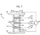
- Fig. 7 is a schematic drawing of a system for improving the stability of a lift truck by reducing the vibration in the lift truck.
- Embodiments of the invention described herein, either alone or in combination, are well suited to provide a dynamically stabilized lift truck, including, for example, a dual-purpose fork lift truck that may be operated as an automated robotic vehicle and also as a standard manually operated truck.
- the truck achieves stabilization through one or more individual or combined improvements that are configured to effect motion in any one of three axes, and in some embodiments, plus reduce vibration.
- the collective improvements provide protection for sensitive electronic components, increase operator comfort, and allow greater productivity by permitting faster travel speeds.
- features of the invention allow for the creation of a dynamically stable platform for mounting sensitive electronic components, such as sensors, controls, and position detecting/reporting equipment, which allows the components to be more effective, regardless of the floor conditions.
- the dynamically stabilized truck and platform allows the sensors and control equipment to generate better quality data, and to ensure more reliable operation. With better quality data, the truck may be allowed to travel faster due to more confidence in the accuracy of the data it produces. And, when the truck can travel faster and operate more reliably, the truck will likely generate more productivity.
- the improved stability control systems and methods can be described as including a variety of unique features, where each feature can individually contribute to the improved stability of the truck in is own way, and each can be combined with one or more of the others to contribute to the improved stability of the truck in combination. Therefore, each of the unique features will be described separately below.
- a lift truck 50 strikes a floor condition that affects only one side, such as when only one wheel, such as caster wheel 52, strikes a crack 54 in the floor 56, and side 58 of the truck 50 is forced up due to the motion, the resultant side to side motion is commonly called roll, and is shown as movement 70 about the X-axis 12.
- the effect of roll causes the entire truck to move or tilt to one side (the side 60 of the truck 50 with the wheel that did not strike the crack), and mechanical and/or electronic components 64 such as any sensory equipment mounted on a platform 62 will also be directed to the same side.
- the components 64 such as a sensor, mounted several feet away from the original point of movement, such as the caster wheel 52, will have its reaction exaggerated.
- the sudden movement caused by the floor condition can diminish the effectiveness of the electronic components and may cause the truck to be operated at slower speeds to reduce the effects of the floor conditions. Slower operating speeds may equate to an undesirable reduction in overall equipment productivity. Sudden movement at one or more wheels may result in an undesirable overall vehicle movement and can be detected and mitigated by actively controlling one or more of the resultant forces in any of the three axis, for example one or both of pitch (rotation or movement about the Y-axis) and roll of the truck.
- prior methods suffer from not monitoring the orientation, e.g., pitch and/or roll of the truck.
- the casters In an improved lift truck, the casters only need to provide a reactant force when the truck is moving away from horizontal in either pitch or roll. If the truck is horizontal, or not changing quickly from horizontal, then the caster spring could be very soft.
- Prior solutions respond to vertical motion of the caster wheel regardless of whether the vertical motion is tilting the truck or not.
- Systems and methods measure the angular speed of rotation of the truck 50 around the X-axis 12, the Y-axis 14, and in the Z-axis 16.
- roll 70 is described as the movement, e.g., rotational speed, about the X-axis 12 in degrees per second, or dps.
- pitch 72 is described as movement, e.g., the rotational speed, about the Y-axis 14. This angular speed of rotation around the X and Y-axis may be measured to provide a numerical value of the measured roll 70 and/or pitch 72.
- the systems and methods may be configured to "lock" one or more of the casters 52 to control the roll and/or pitch.
- "lock” means to stop the motion of the caster(s) in the Z-axis so it behaves like a fixed caster, or like a caster with an extremely hard spring.
- An actuator 76 locks the caster so it can act like a fixed caster.
- a locked caster may not expand or retract, or it would take great force to expand or retract, compared to an unlocked state.
- the motion of the caster is locked suddenly, and in an alternative embodiment, the motion is locked over a predetermined amount of time.
- the motion of the casters may also be locked in relation to other factors, such as speed of the truck, or the weight of the truck or load, or the height of the load, or steering angle, or any combination.
- the casters may be unlocked.
- the predetermined duration of lock time for the locked casters may be a fixed duration, or, similar to locking the motion of the castors, it may be varied with vehicle speed and/or other factors. For example, at low speeds, the duration for locked casters may be longer than at high speeds. In one embodiment, at very low speeds, with the load raised, all the casters may be locked to create a temporary "fixed" caster truck configuration. Alternatively, the force on the left and right casters may be sensed, and the sensed force on each caster may be compared to determine when one or more of the casters could be unlocked.
- a method for control of caster locking using feedback control of angular speed. It is to be appreciated that the systems and methods are adaptable for one or more of the resultant forces in any of the three axis to control, for example, either or both of pitch 72 and roll 70 together or individually, and can use feedback of any of the factors described above, or other factors that would be known to one of skill in the art.
- the caster locking/unlocking algorithm 80 may start with an initialization process indicated as KEY ON at process block 82.
- the algorithm checks and/or adjusts, i.e., calibrates a GZERO stationary value 81 that represents zero degrees per second or "dps" for a GYRO signal 83 received from a gyroscope 84 while the truck is stationary.
- a gyroscope is preferably positioned at or generally near an axis of rotation.
- one or more accelerometers 85 may be used and may be placed in other available locations on the truck.
- the GYRO signal 83 represents a roll 70, in dps, around the X-axis 12.
- the truck When the gyroscope 84 sends a signal having a dps value greater than the value of GZERO, the truck is rolling (i.e., tilting) over to the right at GYRO-GZERO dps.
- a GYRO signal 83 having a dps value smaller than GZERO indicates the truck is rolling (i.e., tilting) to the left at GZERO-GYRO dps.
- the KEY ON initialization/calibration compensates for small shifts in the gyroscope sensor measurement.
- the algorithm may run in a loop 86, as shown.
- the algorithm waits a predetermined and possibly a fixed amount of time to control how fast the loop 86 runs. In one embodiment, a 10 milli-second wait time may be used, so, in this example, the loop cannot run faster than 100 times a second.
- This example LOOP CYCLE SPEED wait time may be used to give mechanical actuators time to change states. Without allowing a sufficient amount of time for mechanical actuators to change, the software may end up oscillating because it is able to change state faster than the truck is able to change its motion.
- the LOOP CYCLE SPEED wait time may generally be dependent on the truck design, the type of actuators used to lock up the casters, and other delays inherent or built into the system.
- an absolute value of GYRO minus GZERO is compared to a THRESHOLD dps value.
- the system may be configured to stop tilts (e.g., pitch and/or roll) with a dps value equal to or larger than the THRESHOLD dps value and not act upon smaller GYRO signals having a dps value less than or equal to the THRESHOLD value.
- tilts e.g., pitch and/or roll
- the system may not react until the pitch or roll dps is at or exceeds THRESHOLD, typically where the GRYO signal is far from zero, although not a requirement.
- the algorithm continues to decision block 92, where it may simply check any lock timers (e.g., LOCK TIMER L, LOCK TIMER R) to determine if they are ON, and if they are, the algorithm continues to decision block 94 to determine if any lock timers have been ON for a predetermined DURATION. If any timer is at or exceeds the DURATION, then the appropriate LOCK TIMER L or LOCK TIMER R may be turned OFF and reset, e.g., to zero msec. The loop 86 may then repeat by going back to process block 88, LOOP CYCLE SPEED. This permits a short predetermined period of time for the truck to respond.
- lock timers e.g., LOCK TIMER L, LOCK TIMER R
- the truck will start to tilt, and the GYRO signal will shift away from GZERO by more than THRESHOLD.
- the algorithm determines which way the truck is rolling by whether the GYRO signal is larger than GZERO or smaller than GZERO. Based on this determination, the algorithm branches to either the set LOCK R process block 98 or the set LOCK L process block 100, and locks up the caster on that side for the pre-determined DURATION.
- the LOCK R (or LOCK L) is set to ON, and the LOCK TIMER R (or LOCK TIMER L) is set to DURATION.
- the truck is thereby prevented from rolling in that direction and should, after some time delay, cause the GYRO signal to return to GZERO or at least make the absolute value of GYRO minus GZERO less than THRESHOLD.
- embodiments of the invention may allow the truck to tilt slowly.
- An advantage of the systems and methods described herein is that a rapid roll to either side or oscillation (rocking around the roll axis) is stopped.
- a truck making a sudden turn may have the outside caster lock up to prevent rolling as the truck makes the turn.
- the left caster may lock up to prevent rolling. But if the operator shifts the load and waits for several DURATION periods, then the truck may slowly lean toward the heavy side.
- This slow tilt feature of the invention is useful and important. Useful because it lets the spring loaded casters adjust for wear so the traction tire always has good contact force with the floor.
- the traction tire may be the main source for control and braking, and it is important that the traction wheel maintain contact with the proper force against the floor surface.
- the algorithm repeats the loop 86 by going back to process block 88, CYCLE SPEED LIMIT.
- the actuator 76 locks the left or right side caster 52 so the caster acts like a fixed caster.
- the actuator 76 could be a magneto-rheological (MR) fluid filled damper.
- MR damper is able to lock up in about 20 milli-seconds, or more or less, while others are able to lock up in about 8 to 10 milli-seconds, or more or less, and stop the caster from compressing the caster spring 78.
- the caster may still have spring(s), but the springs could be soft so that a rough floor would not annoy the operator.
- the DURATION period is set long enough to account for most shocks or tilts due to sharp turns or other obstacles that would tilt a truck with soft or even hard springs.
- a typical DURATION could range from about 0.1 seconds to about 5 seconds, or more or less, and may be predetermined in the algorithm for a particular truck design or truck application.
- the algorithm and associated system may be able to adjust the DURATION period for long durations at low speeds and shorter durations at high speeds. At high speeds, the truck would complete the turn, or roll over the bump in the floor, in a much shorter time than at low speeds.
- Embodiments according to the invention provide several benefits and advantages that cannot be obtained in existing truck configurations. For example, embodiments of the invention enable the truck to stay level instead of rocking due to uneven floors. This is beneficial to the operator standing on the truck because a rocking truck may increase operator fatigue. In lifting loads onto or off of high racks or stacks, embodiments of the invention may lock both the left and right casters to make the mast more stable and stay vertical. Embodiments of the invention may also be more economical than fixed caster and floating traction wheel alternatives. Also, the ride quality may be much improved over fixed casters that typically transmit every bump into the platform the operator stands on.
- Embodiments of the invention will also allow use of very soft springs so the ride quality can be better than spring casters and spring-damper-caster designs.
- the invention detects and stops the pitch and/or roll while other known alternative designs do not detect the truck pitch or roll.
- actuators 76 are contemplated for use with the invention.
- small hydraulic cylinders with a rapid response profile are available.
- solenoid based actuators could use an electromagnet to lock the caster into a fixed position.
- Pneumatic cylinders can be used to increase or decrease the force of the caster on the floor in parallel with springs, or in place of the mechanical springs.
- the MR actuator could act as a variable damper that increases the mechanical resistance based on the rotation speed (e.g., roll and/or pitch) instead of locking the caster solid.
- Hydraulic and pneumatic actuators can also act as sensors to detect caster compression and measure, or predict, the truck tilting.
- the hydraulic system could shut a valve to lock the caster, and the pneumatic system could open a valve to reduce pressure from a compressing caster or apply more pressure to extend a caster to exert more force on the floor.
- Additional materials including piezoelectric composites and electroactive polymers, or EAPs, are also contemplated for actuator use. Piezoelectric composites can be used for both sensor and actuator functions. Piezoelectric materials can convert electrical signals into useful displacement or force. EAPs are polymers that exhibits a change in size or shape when stimulated by an electric field. A beneficial characteristic property of an EAP is that they are able to undergo a large amount of deformation while sustaining large forces.
- a variety of different sensors are contemplated for use with embodiments of the invention.
- a variety of gyroscope configurations are available, such as a solid state Micro-electromechanical Systems (MEMS) gyroscope.
- MEMS Micro-electromechanical Systems
- sensors or combinations of sensors that can replace a true gyroscope.
- the rotation of the truck could be sensed by differential accelerometers, such as two Z-axis accelerometers with one mounted on each side of the truck. For rolls around the X-axis 12, the difference between the Z-axis 16 acceleration on the right and left side would indicate a roll is happening.
- the tilt of the truck could be measured by mechanical devices used as sensors.
- the compression of the spring 78 for each caster 52 could be measured by any type of proximity sensor.
- the vertical location of one or more of the casters can be used to infer the truck tilt, or to predict that the truck will tilt due to unequal forces.
- hydraulic or pneumatic cylinders convert caster compression into a change in fluid pressure or fluid volume. Again, the vertical position of each caster, and the force it is exerting to tilt the truck, can be inferred from measuring the fluid pressure or fluid volume. For example, with a pneumatic cylinder, the contraction of the caster will increase the gas pressure. For a hydraulic cylinder, compression of the caster will force fluid out of the cylinder and into an expansion chamber. In addition to sensing or predicting truck tilt, these devices can also be used to lock the caster or apply force to stop the truck tilting.
- the pitch around the Y-axis 14 can be controlled just as the roll around the X-axis 12.
- the caster springs typically allow the truck mast to tilt, which is not desired. The tilting may make it more difficult to put the load on a shelf.
- One possible application for an embodiment of the invention would be to let the operator manually, or the truck software automatically, lock one or more of the casters while the load is some predetermined height above the floor. In this configuration, for example, for a short distance at low speeds, the truck could have fixed casters that would keep the mast from tilting.
- the invention may embody predictive control.
- the truck may use power steering, a measured steering angle, or have limit switches that indicate the position of the steering controls.
- the truck software may anticipate the truck tilting due to steering position, truck speed, fork height above the floor, and/or other inputs from the operator. It is to be appreciated that the truck software could trigger a lock before the gyroscope 84 senses any tilt. And, the software described may release the lock after DURATION has passed (assuming the gyroscope senses no rotation larger than THRESHOLD).
- Stability control parameters may be accessible on a local or remote computer system, such as a fleet management system, for example, to set or adjust one or more stability control parameters for a truck.
- Stability control parameters may be set or adjusted based on a variety of factors, such as type of truck, type of load, load weight, and/or the operator, as non-limiting examples.
- Stability measurements that monitor truck motion such as data from accelerometers and gyroscopes, may also be passed on to the fleet management system.
- the accelerometers can report impacts, and the gyroscopes may provide an indication that the truck casters need adjustment. This data may be recorded and available for analysis and display on a system monitor, for example.
- Some embodiments may use a wide range of systems and methods to adjust the truck stability, and each may be used alone or in combination with other stability controls.
- Some embodiments may use a steered caster. In this configuration, the caster orientation may be monitored and controlled to maximize stability.
- a reduction in the permitted acceleration and speed of the truck could be used in combination with other systems and methods for stability control. For example, when a truck is turning, the casters may be locked to stop or reduce a roll. If that doesn't stop the roll, to a predetermined degree, then one or more factors affecting stability may be limited, such as the acceleration of the truck, and then another factor may be limited, such as speed of the truck, and so on, to reduce or stop the truck roll.
- a vertical support 110 may be composed of two or more cylinders 112, 114 that function as a spring-mass-damper or tuned mass-damper system.
- Each vertical support may be constructed similar to a piston or hydraulic (pneumatic) cylinder and may be filled with a spring 116 and a fluid 118 (e.g., air, liquid).
- the fluid 118 may be ported to an orifice 120, such as a variable valve, and to a reservoir 122.
- the orifice 120 may be electrically controlled via a control circuit 124, which may optionally include an amplifier 126, to allow a variable amount of fluid motion.
- an accelerometer 128 is used in the vertical axis (Z-axis 16) to detect movement with respect to time. Single and multi-axis models of accelerometers are available to detect magnitude and direction of the acceleration. If the acceleration is high, for example, as from a sudden shock to the truck when contacting a bump, the control circuit 124 may allow a fast fluid flow through the orifice providing cushioning, with the spring 116, to a portion of the vertical support, effectively serving as a shock absorber. If the acceleration rates are small, the fluid movement may be limited, thereby keeping the vertical movement minimal.
- This embodiment is well suited to provide a more stable platform 62 (see Fig. 4 ) for mounting components 64 on the vertical supports 110. If the detected motion from a shock can be mitigated or even cancelled, the truck may then be capable of traveling faster without the potential adverse effects to components, or loss or degradation of data.
- a more stable mounting platform for sensitive sensory components also improves the quality of data produced, allowing greater flexibility in the use of the vehicle in either automatic or manual modes.
- An additional aspect of the invention describes an embodiment of the invention including vibration control. Vibration can develop in most mechanical bodies during normal operation. While vibrations usually do not exhibit the same peak energy levels as the contact of an obstacle, it can cause other problems. Within a mechanical body, a vibration can cause small movements that occur at specific frequencies. In some cases, the mechanical structure, by virtue of its shape and mass, can develop resonances that may have the effect of creating oscillations.
- a vertical support 130 may be used for mounting the platform 62 and associated components 64.
- the support 130 may transmit vibrations experienced from truck motion through the support 130 and to the components 64. Damping the vibrations may be beneficial to the integrity of the sensor equipment and other components 64, and the quality of data produced.
- construction of the vertical support 130 may use hollow tubing 140.
- the tubing 140 may contain one or more plugs or sections 142 partially or completely filled with, for example, a phase changing, energy absorbing material such as Magneto-rheological (MR) fluid.
- MR Magneto-rheological
- the smaller particles within the MR fluid can move with respect to each other and can dampen higher frequency vibration that the vertical support experiences.
- Piezoelectric materials and electroactive polymers are also considered for use in tubing 140.
- the phase changing material in the sections 142 may be electrically controlled via the control circuit 124, which may optionally include an amplifier 126, to allow a variable amount of phase change in the phase changing material.
- An alternative embodiment describes an active vibration dampening system built into the support structure of the truck.
- the system uses accelerometers 144 to detect vibration and movement both at the mounting frame base 146 and at the stabilized platform 62. Vibration frequencies that are detected in the mounting frame 146 may travel through the tubing 140 to the platform 62 if not acted upon.
- a phase changing or variable viscosity material may be used, such as MR fluid, to change the shape of the resonant cavity in the support structure tubing 140, thereby dampening vibrations and/or any oscillations that start to occur.
- MR fluid phase changing or variable viscosity material
- the tubing material 140 that the vertical support 130 is made from can be filled with one or more granular or pelletized materials 148, such as metal shot, plastic beads, or sand, as non-limiting examples.
- the ability of the particles to move against each other may help dissipate the higher frequency vibration energy and reduce and resultant undesirable motion.
- the vertical support 130 can be mounted anywhere on the truck 50. It is also to be appreciated that any of the above embodiments can be combined to provide vibration control.
- any of the processes or steps described herein may be combined, eliminated, or reordered.
- instructions may reside in computer readable medium wherein those instructions are executed by a processor to perform one or more of processes or steps described herein.
- any of the processes or steps described herein can be implemented as hardware, software, including program instructions executing on a computer, or a combination of hardware and software. Accordingly, this description is meant to be taken only by way of example, and not to otherwise limit the scope of this invention.
Landscapes
- Engineering & Computer Science (AREA)
- Mechanical Engineering (AREA)
- Transportation (AREA)
- Structural Engineering (AREA)
- General Engineering & Computer Science (AREA)
- Combustion & Propulsion (AREA)
- Life Sciences & Earth Sciences (AREA)
- Chemical & Material Sciences (AREA)
- Geology (AREA)
- Civil Engineering (AREA)
- Physics & Mathematics (AREA)
- Acoustics & Sound (AREA)
- Aviation & Aerospace Engineering (AREA)
- Vehicle Body Suspensions (AREA)
- Forklifts And Lifting Vehicles (AREA)
Applications Claiming Priority (1)
| Application Number | Priority Date | Filing Date | Title |
|---|---|---|---|
| US201161454188P | 2011-03-18 | 2011-03-18 |
Publications (3)
| Publication Number | Publication Date |
|---|---|
| EP2500238A2 true EP2500238A2 (de) | 2012-09-19 |
| EP2500238A3 EP2500238A3 (de) | 2013-12-25 |
| EP2500238B1 EP2500238B1 (de) | 2016-05-11 |
Family
ID=45872822
Family Applications (2)
| Application Number | Title | Priority Date | Filing Date |
|---|---|---|---|
| EP12159605.0A Active EP2500238B1 (de) | 2011-03-18 | 2012-03-15 | Dynamische Vibrationssteuersysteme und Verfahren für Industriegabelstapler |
| EP12160108.2A Active EP2500239B1 (de) | 2011-03-18 | 2012-03-19 | Dynamische Vibrationssteuersysteme und Verfahren für Industriegabelstapler |
Family Applications After (1)
| Application Number | Title | Priority Date | Filing Date |
|---|---|---|---|
| EP12160108.2A Active EP2500239B1 (de) | 2011-03-18 | 2012-03-19 | Dynamische Vibrationssteuersysteme und Verfahren für Industriegabelstapler |
Country Status (6)
| Country | Link |
|---|---|
| US (1) | US9403667B2 (de) |
| EP (2) | EP2500238B1 (de) |
| CN (1) | CN102701112B (de) |
| AU (1) | AU2012201506B2 (de) |
| CA (1) | CA2770863C (de) |
| HK (1) | HK1174890A1 (de) |
Families Citing this family (20)
| Publication number | Priority date | Publication date | Assignee | Title |
|---|---|---|---|---|
| US8731785B2 (en) * | 2011-03-18 | 2014-05-20 | The Raymond Corporation | Dynamic stability control systems and methods for industrial lift trucks |
| US9403667B2 (en) * | 2011-03-18 | 2016-08-02 | The Raymond Corporation | Dynamic vibration control systems and methods for industrial lift trucks |
| US9302893B2 (en) * | 2013-02-07 | 2016-04-05 | The Raymond Corporation | Vibration control systems and methods for industrial lift trucks |
| US10315900B2 (en) * | 2014-04-01 | 2019-06-11 | The Raymond Corporation | Caster wheel with constant force mechanism |
| US10114379B2 (en) * | 2015-06-01 | 2018-10-30 | Dpix, Llc | Point to point material transport vehicle improvements for glass substrate |
| CN104943664A (zh) * | 2015-06-30 | 2015-09-30 | 苏州先锋物流装备科技有限公司 | 铰接式平衡轮机构 |
| DE102016207523A1 (de) * | 2016-05-02 | 2017-11-02 | Jungheinrich Aktiengesellschaft | Flurförderzeug mit einer Einrichtung zur Reduzierung von Querschwingungen |
| DE102016207526A1 (de) | 2016-05-02 | 2017-11-02 | Jungheinrich Aktiengesellschaft | Flurförderzeug mit einer Einrichtung zur Reduzierung von Schwingungen |
| DE102016208205A1 (de) | 2016-05-12 | 2017-11-16 | Jungheinrich Aktiengesellschaft | Flurförderzeug mit einer Einrichtung zur Reduzierung von Schwingungen |
| DE102016209893A1 (de) | 2016-06-06 | 2017-12-07 | Jungheinrich Aktiengesellschaft | Flurförderzeug mit einer Einrichtung zur Reduzierung von Schwingungen |
| EP3473585B1 (de) * | 2016-06-16 | 2023-12-06 | Mitsubishi Logisnext Co., Ltd. | Industriefahrzeug |
| DE102016211390A1 (de) | 2016-06-24 | 2017-12-28 | Jungheinrich Aktiengesellschaft | Flurförderzeug mit Mitteln zur Unterdrückung bzw. Reduzierung von Schwingungen |
| DE102016211603A1 (de) | 2016-06-28 | 2017-12-28 | Jungheinrich Aktiengesellschaft | Abstützvorrichtung mit Einrichtung zur Reduzierung von Schwingungen |
| CN107601391A (zh) * | 2017-09-22 | 2018-01-19 | 太仓市高泰机械有限公司 | 一种液压车的自动感应及自锁方法 |
| CN107601390A (zh) * | 2017-09-22 | 2018-01-19 | 太仓市高泰机械有限公司 | 一种带有自锁功能的液压车的工作方法 |
| TWI670924B (zh) * | 2018-07-02 | 2019-09-01 | 義守大學 | 振動控制系統 |
| CN110872083B (zh) * | 2018-09-03 | 2023-07-14 | 鹏亚机械科技(上海)有限公司 | 一种升降平台 |
| USD907564S1 (en) * | 2019-04-02 | 2021-01-12 | The Raymond Corporation | Vehicle mast |
| CN111646396B (zh) * | 2020-06-18 | 2021-08-03 | 江西鑫铂瑞科技有限公司 | 一种铜箔生产生箔机成品自动搬运装置 |
| US20230058101A1 (en) * | 2021-08-23 | 2023-02-23 | Brandon Michael West | Powered Industrial Truck (PIT) with Rear-Loading/Lifting Mechanism |
Family Cites Families (83)
| Publication number | Priority date | Publication date | Assignee | Title |
|---|---|---|---|---|
| DE957377C (de) | 1953-10-25 | 1957-01-31 | Miag Muehlenbau & Ind Gmbh | Hubvorrichtung fuer Flurfoerdergeraete |
| US2746768A (en) * | 1954-11-04 | 1956-05-22 | Gen Motors Corp | Wheel hop damper attachment for vehicle road wheels |
| US2982395A (en) | 1958-12-08 | 1961-05-02 | Harbor Boat Building Company | Reusable shipping container |
| US3031024A (en) | 1959-07-23 | 1962-04-24 | Yale & Towne Mfg Co | All directional industrial truck |
| US3067839A (en) | 1961-03-29 | 1962-12-11 | Raymond Corp | Material handling vehicle |
| US3504889A (en) | 1968-03-18 | 1970-04-07 | Midland Ross Corp | Portable vehicle lift |
| US3672634A (en) | 1969-07-28 | 1972-06-27 | Ezy Way Mfg & Sales Co | Lifting apparatus |
| US3918597A (en) | 1971-10-14 | 1975-11-11 | Lee Inventions Inc | Method of moving a heavy load |
| US4037739A (en) | 1974-05-07 | 1977-07-26 | Lee Inventions, Inc. | Moving system with integral casters |
| JPS57160708A (en) | 1981-03-27 | 1982-10-04 | Nissan Motor Co Ltd | Rear wheel suspension for one-sided wheel drive type four-point support car |
| US4509127A (en) | 1981-03-31 | 1985-04-02 | Kabushiki Kaisha Toyoda Jidoh Shokki Seisakusho | Control device for loading and unloading mechanism |
| JPS58167214A (ja) | 1982-03-27 | 1983-10-03 | Toyoda Autom Loom Works Ltd | 産業車両における車軸固定装置 |
| US4530492A (en) | 1983-05-25 | 1985-07-23 | Bork Robert L | Apparatus for supporting vehicle body parts |
| US5020825A (en) | 1987-03-18 | 1991-06-04 | Monroe Auto Equipment Company | Method and apparatus for absorbing mechanical shock |
| US5107969A (en) | 1987-09-17 | 1992-04-28 | Alfred Teves Gmbh | Controllable vibration damper |
| JP2699201B2 (ja) | 1989-07-12 | 1998-01-19 | 同和鉱業株式会社 | 酸化物超電導焼結体の製造方法 |
| US5289902A (en) | 1991-10-29 | 1994-03-01 | Kabushiki Kaisha Toshiba | Elevator |
| US5269501A (en) | 1992-12-03 | 1993-12-14 | Hein-Werner Corporation | Vehicle and vehicle parts transportation system |
| JPH06263145A (ja) | 1993-03-10 | 1994-09-20 | Pfu Ltd | スクラップ箱、スクラップ排出装置及び排出方法 |
| JP2736607B2 (ja) | 1994-05-30 | 1998-04-02 | 浅香工業株式会社 | ロールボックスの格納装置 |
| JPH0899513A (ja) | 1994-09-29 | 1996-04-16 | Unisia Jecs Corp | 車両懸架装置 |
| US5647600A (en) | 1995-01-09 | 1997-07-15 | American Wholesale Beverage Co., Inc. | Cart |
| US5579859A (en) | 1995-02-10 | 1996-12-03 | Crown Equipment Corporation | Isolated floor for material handling vehicle |
| US5628377A (en) | 1995-06-16 | 1997-05-13 | M I C, Societe Anonyme | Goods-handling cart with stabilizing wheels |
| JPH0986610A (ja) | 1995-09-26 | 1997-03-31 | Murata Mach Ltd | カゴ台車用自動倉庫 |
| DE59505399D1 (de) | 1995-11-30 | 1999-04-22 | Siemag Transplan Gmbh | Verfahren zum Regeln eines rechnergesteuerten Regalbediengerätes |
| US5878851A (en) | 1996-07-02 | 1999-03-09 | Lord Corporation | Controllable vibration apparatus |
| DE19641192C2 (de) | 1996-09-24 | 2002-10-31 | Siemens Ag | Handhabungsgerät, insbesondere Regalbediengerät |
| US5993358A (en) | 1997-03-05 | 1999-11-30 | Lord Corporation | Controllable platform suspension system for treadmill decks and the like and devices therefor |
| JPH1120442A (ja) | 1997-07-08 | 1999-01-26 | Toyota Autom Loom Works Ltd | 産業車両用揺動制御装置 |
| JPH11100200A (ja) | 1997-09-30 | 1999-04-13 | Komatsu Forklift Co Ltd | フォークリフトトラックの懸架装置 |
| NZ503092A (en) | 1997-09-30 | 2002-12-20 | Crown Equip Corp | Computer controlled braking system for a forklift |
| JPH11165998A (ja) | 1997-12-04 | 1999-06-22 | Toyota Autom Loom Works Ltd | 産業車両の車体揺動制御装置及び産業車両 |
| DE19802119A1 (de) | 1998-01-21 | 1999-07-22 | Still Wagner Gmbh & Co Kg | Flurförderzeug mit einer Hubvorrichtung |
| JP3601294B2 (ja) | 1998-04-22 | 2004-12-15 | 株式会社豊田自動織機 | 産業車両の車体揺動制御装置 |
| JP2000062428A (ja) | 1998-08-21 | 2000-02-29 | Toyota Autom Loom Works Ltd | 産業車両の車体揺動制御装置 |
| JP4245722B2 (ja) | 1999-02-17 | 2009-04-02 | 住友ナコ マテリアル ハンドリング株式会社 | フォークリフトの車軸揺動装置 |
| FR2796887B1 (fr) | 1999-07-27 | 2002-11-15 | Lohr Ind | Dispositif d'amortissement des mouvements de lacet d'une remorque routiere tractee par un vehicule a moteur |
| US6517094B1 (en) | 2000-03-30 | 2003-02-11 | American Axle & Manufacturing, Inc. | Hydraulic anti-roll suspension system for motor vehicles |
| US6279199B1 (en) | 2000-06-13 | 2001-08-28 | Ross Design & Engineering, Inc. | Vertically adjustable caster |
| DE10033801A1 (de) | 2000-07-12 | 2002-01-24 | Fiat Om Carrelli Elevatori | Flurförderzug |
| US7070028B2 (en) | 2001-02-07 | 2006-07-04 | Tenneco Automotive Operating Company Inc. | Frequency dependent damper |
| US20030070850A1 (en) * | 2001-02-16 | 2003-04-17 | Cellex Power Products, Inc. | Hybrid power supply apparatus for battery replacement applications |
| US6601825B2 (en) | 2001-02-22 | 2003-08-05 | Alum-A-Lift, Inc. | Portable and demountable lifting device |
| US6499184B2 (en) | 2001-05-14 | 2002-12-31 | Ross Design & Engineering, Inc. | Elastomeric biased caster |
| DE10126933B4 (de) | 2001-06-01 | 2004-08-26 | Continental Aktiengesellschaft | Verfahren zur Regelung oder Steuerung der Dämpferkraft verstellbarer Dämpfer an Fahrzeugen |
| JP2002370899A (ja) | 2001-06-14 | 2002-12-24 | Mitsubishi Heavy Ind Ltd | フォークリフト車両 |
| GB2379434B (en) | 2001-09-10 | 2004-09-22 | Lansing Linde Ltd | Industrial truck with a lifting frame |
| FR2837809B1 (fr) | 2002-03-29 | 2004-11-12 | Manitou Bf | Chariot elevateur a portee variable a trois roues |
| JP2004001941A (ja) | 2002-05-31 | 2004-01-08 | Tcm Corp | マスト装置 |
| US7017228B2 (en) | 2002-10-02 | 2006-03-28 | Harlan Silverstein | Pneumatic locking swivel caster |
| CN1211543C (zh) * | 2003-01-17 | 2005-07-20 | 姜袁 | 碟式竖向隔震耗能阻尼器 |
| JP2004269236A (ja) | 2003-03-12 | 2004-09-30 | Nippon Yusoki Co Ltd | フォークリフト |
| US7008166B1 (en) | 2003-06-05 | 2006-03-07 | Honda Giken Kogyo Kabushiki Kaisha | Door lifting apparatus and method |
| US7073643B2 (en) | 2003-10-27 | 2006-07-11 | Tenneco Automotive Operating Company Inc. | Compensated rod for a frequency dependent damper shock absorber |
| US20050173849A1 (en) | 2004-02-10 | 2005-08-11 | Bart Vandewal | Electronically controlled frequency dependent damping |
| DE102004019072A1 (de) | 2004-04-20 | 2005-11-17 | Om Carrelli Elevatori S.P.A. | Flurförderzeug, insbesondere Gabelhubwagen |
| US20060138733A1 (en) | 2004-08-11 | 2006-06-29 | Luke Clauson | Suspension adjustment system |
| DE102004048519A1 (de) | 2004-08-23 | 2006-03-02 | Sandt Logistik Gmbh | Antriebsregelung für ein Regalbediengerät |
| US20060182578A1 (en) | 2005-01-26 | 2006-08-17 | Escalera, Inc. | Cart & dual use ramp for console copier relocation |
| JP4546308B2 (ja) | 2005-03-30 | 2010-09-15 | 本田技研工業株式会社 | 可変減衰力ダンパーの制御装置 |
| US7770904B2 (en) * | 2005-04-14 | 2010-08-10 | Nmhg Oregon, Llc | Stability system for an industrial vehicle |
| US20060232030A1 (en) * | 2005-04-14 | 2006-10-19 | Nmhg Oregon, Llc | Multi-axis load rollers for an industrial vehicle |
| CA2559463A1 (en) | 2005-09-15 | 2007-03-15 | Dynatool Industries Inc. | Powered locking caster wheel |
| DE102005053264A1 (de) | 2005-11-08 | 2007-05-10 | Still Gmbh | Mobile Arbeitsmaschine mit einem Fahrerplatz |
| SE531618C2 (sv) | 2006-02-23 | 2009-06-09 | Oehlins Racing Ab | Elektrisk styrd trycksatt dämpare |
| US20070231113A1 (en) | 2006-03-10 | 2007-10-04 | Mcgurn Arthur S | Apparatus and method for lifting and transporting a container with an independent mechanized unit |
| CN2889874Y (zh) | 2006-03-23 | 2007-04-18 | 历德奎 | 立式弓片减振器 |
| US20090312875A1 (en) | 2006-07-12 | 2009-12-17 | Lasse Lehtonen | Method and an arrangement for dampening vibrations in a mast structure |
| JP2008081261A (ja) | 2006-09-28 | 2008-04-10 | Toyota Industries Corp | フォークリフトにおける振動抑制装置 |
| US7888901B2 (en) | 2006-11-15 | 2011-02-15 | Honeywell International Inc. | Active human-machine interface system including an electrically controllable damper |
| DE102007015488A1 (de) | 2007-03-30 | 2008-10-02 | Still Wagner Gmbh | Schwingungskompensation am Hubgerüst eines Flurförderzeugs |
| DE102007038016A1 (de) | 2007-08-10 | 2009-02-12 | Iveco Magirus Ag | Drehleiter |
| US7905555B2 (en) | 2007-08-16 | 2011-03-15 | Global Polymer Industries, Inc. | Yaw control system for a vehicle-trailer combination |
| DE102007045211B4 (de) | 2007-09-21 | 2010-11-11 | Ford Global Technologies, LLC, Dearborn | Verfahren und eine Vorrichtung zum elektrisch gesteuerten Unterstützen einer Fahrzeugbewegung eines Fahrzeugs |
| US7896358B2 (en) | 2007-10-25 | 2011-03-01 | The Raymond Corporation | Magneto-rheological inertial damping system for lift trucks |
| DE102008020595B4 (de) | 2008-04-24 | 2022-02-10 | Linde Material Handling Gmbh | Verfahren zur Schwingungsdämpfung bei Flurförderzeugen |
| US8967648B2 (en) | 2009-03-12 | 2015-03-03 | Arvinmeritor Technology, Llc | Continuous force control for dual air spring configuration |
| US8140228B2 (en) | 2009-03-27 | 2012-03-20 | The Raymond Corporation | System and method for dynamically maintaining the stability of a material handling vehicle having a vertical lift |
| RU2012139461A (ru) * | 2010-02-17 | 2014-03-27 | Лифтер С.Р.Л. | Транспаллета |
| KR101720704B1 (ko) | 2010-03-12 | 2017-03-28 | 심보틱 엘엘씨 | 보충 및 주문 이행 시스템 |
| DE102010016062A1 (de) | 2010-03-22 | 2011-09-22 | Technische Universität München | Dämpfung oder Vermeidung von Schwingungen bei Flurförderzeugen |
| US9403667B2 (en) * | 2011-03-18 | 2016-08-02 | The Raymond Corporation | Dynamic vibration control systems and methods for industrial lift trucks |
-
2011
- 2011-12-06 US US13/312,722 patent/US9403667B2/en active Active
-
2012
- 2012-03-13 CA CA2770863A patent/CA2770863C/en active Active
- 2012-03-14 AU AU2012201506A patent/AU2012201506B2/en active Active
- 2012-03-15 EP EP12159605.0A patent/EP2500238B1/de active Active
- 2012-03-16 CN CN201210157172.0A patent/CN102701112B/zh active Active
- 2012-03-19 EP EP12160108.2A patent/EP2500239B1/de active Active
-
2013
- 2013-02-18 HK HK13102058.0A patent/HK1174890A1/zh unknown
Non-Patent Citations (1)
| Title |
|---|
| None |
Also Published As
| Publication number | Publication date |
|---|---|
| US20120235100A1 (en) | 2012-09-20 |
| EP2500239A2 (de) | 2012-09-19 |
| CN102701112B (zh) | 2016-04-13 |
| US9403667B2 (en) | 2016-08-02 |
| HK1174890A1 (zh) | 2013-06-21 |
| EP2500238A3 (de) | 2013-12-25 |
| AU2012201506A1 (en) | 2012-10-04 |
| CA2770863A1 (en) | 2012-09-18 |
| AU2012201506B2 (en) | 2014-09-11 |
| EP2500239B1 (de) | 2015-10-14 |
| EP2500238B1 (de) | 2016-05-11 |
| CA2770863C (en) | 2019-06-25 |
| EP2500239A3 (de) | 2013-12-25 |
| CN102701112A (zh) | 2012-10-03 |
Similar Documents
| Publication | Publication Date | Title |
|---|---|---|
| EP3260349B1 (de) | Verfahren zur dynamischen stabilitätssteuerung für gabelstapler | |
| EP2500239B1 (de) | Dynamische Vibrationssteuersysteme und Verfahren für Industriegabelstapler | |
| US9302893B2 (en) | Vibration control systems and methods for industrial lift trucks | |
| US7729829B2 (en) | Suspension irregularity detecting system | |
| US7896358B2 (en) | Magneto-rheological inertial damping system for lift trucks | |
| JP5057034B2 (ja) | トラックの荷台防振構造 | |
| JP2005507062A (ja) | 液体ばね装置のばね剛性のシームレス制御 | |
| JP2005507062A5 (de) | ||
| JP3334582B2 (ja) | 産業車両の車体揺動制御装置及び産業車両 | |
| JP2007508185A (ja) | 車両サスペンション制御装置 | |
| JP2009067246A (ja) | 車高調整装置 | |
| JP2021134022A (ja) | 荷役車両の振動防止システム及び荷役車両 | |
| JP3601294B2 (ja) | 産業車両の車体揺動制御装置 | |
| JP2509333B2 (ja) | 車高制御装置 | |
| JP3601296B2 (ja) | 産業車両の車体揺動制御装置 | |
| JP5135023B2 (ja) | サスペンション特性制御装置 | |
| JP2003294392A (ja) | 質量投射装置搭載車両の振動減衰装置 | |
| WO2001098096A1 (en) | Suspension lock-out system and methodology |
Legal Events
| Date | Code | Title | Description |
|---|---|---|---|
| PUAI | Public reference made under article 153(3) epc to a published international application that has entered the european phase |
Free format text: ORIGINAL CODE: 0009012 |
|
| AK | Designated contracting states |
Kind code of ref document: A2 Designated state(s): AL AT BE BG CH CY CZ DE DK EE ES FI FR GB GR HR HU IE IS IT LI LT LU LV MC MK MT NL NO PL PT RO RS SE SI SK SM TR |
|
| AX | Request for extension of the european patent |
Extension state: BA ME |
|
| PUAL | Search report despatched |
Free format text: ORIGINAL CODE: 0009013 |
|
| AK | Designated contracting states |
Kind code of ref document: A3 Designated state(s): AL AT BE BG CH CY CZ DE DK EE ES FI FR GB GR HR HU IE IS IT LI LT LU LV MC MK MT NL NO PL PT RO RS SE SI SK SM TR |
|
| AX | Request for extension of the european patent |
Extension state: BA ME |
|
| RIC1 | Information provided on ipc code assigned before grant |
Ipc: B62B 5/00 20060101ALI20131115BHEP Ipc: B66F 9/24 20060101ALI20131115BHEP Ipc: B62B 3/06 20060101AFI20131115BHEP Ipc: B66F 17/00 20060101ALI20131115BHEP |
|
| 17P | Request for examination filed |
Effective date: 20140520 |
|
| RBV | Designated contracting states (corrected) |
Designated state(s): AL AT BE BG CH CY CZ DE DK EE ES FI FR GB GR HR HU IE IS IT LI LT LU LV MC MK MT NL NO PL PT RO RS SE SI SK SM TR |
|
| 17Q | First examination report despatched |
Effective date: 20141128 |
|
| GRAP | Despatch of communication of intention to grant a patent |
Free format text: ORIGINAL CODE: EPIDOSNIGR1 |
|
| INTG | Intention to grant announced |
Effective date: 20151124 |
|
| GRAS | Grant fee paid |
Free format text: ORIGINAL CODE: EPIDOSNIGR3 |
|
| GRAA | (expected) grant |
Free format text: ORIGINAL CODE: 0009210 |
|
| AK | Designated contracting states |
Kind code of ref document: B1 Designated state(s): AL AT BE BG CH CY CZ DE DK EE ES FI FR GB GR HR HU IE IS IT LI LT LU LV MC MK MT NL NO PL PT RO RS SE SI SK SM TR |
|
| REG | Reference to a national code |
Ref country code: GB Ref legal event code: FG4D |
|
| REG | Reference to a national code |
Ref country code: CH Ref legal event code: EP |
|
| REG | Reference to a national code |
Ref country code: AT Ref legal event code: REF Ref document number: 798403 Country of ref document: AT Kind code of ref document: T Effective date: 20160515 |
|
| REG | Reference to a national code |
Ref country code: IE Ref legal event code: FG4D |
|
| REG | Reference to a national code |
Ref country code: DE Ref legal event code: R096 Ref document number: 602012018249 Country of ref document: DE |
|
| REG | Reference to a national code |
Ref country code: SE Ref legal event code: TRGR |
|
| REG | Reference to a national code |
Ref country code: LT Ref legal event code: MG4D |
|
| REG | Reference to a national code |
Ref country code: NL Ref legal event code: MP Effective date: 20160511 |
|
| PG25 | Lapsed in a contracting state [announced via postgrant information from national office to epo] |
Ref country code: LT Free format text: LAPSE BECAUSE OF FAILURE TO SUBMIT A TRANSLATION OF THE DESCRIPTION OR TO PAY THE FEE WITHIN THE PRESCRIBED TIME-LIMIT Effective date: 20160511 Ref country code: NL Free format text: LAPSE BECAUSE OF FAILURE TO SUBMIT A TRANSLATION OF THE DESCRIPTION OR TO PAY THE FEE WITHIN THE PRESCRIBED TIME-LIMIT Effective date: 20160511 Ref country code: NO Free format text: LAPSE BECAUSE OF FAILURE TO SUBMIT A TRANSLATION OF THE DESCRIPTION OR TO PAY THE FEE WITHIN THE PRESCRIBED TIME-LIMIT Effective date: 20160811 Ref country code: FI Free format text: LAPSE BECAUSE OF FAILURE TO SUBMIT A TRANSLATION OF THE DESCRIPTION OR TO PAY THE FEE WITHIN THE PRESCRIBED TIME-LIMIT Effective date: 20160511 |
|
| REG | Reference to a national code |
Ref country code: AT Ref legal event code: MK05 Ref document number: 798403 Country of ref document: AT Kind code of ref document: T Effective date: 20160511 |
|
| PG25 | Lapsed in a contracting state [announced via postgrant information from national office to epo] |
Ref country code: PT Free format text: LAPSE BECAUSE OF FAILURE TO SUBMIT A TRANSLATION OF THE DESCRIPTION OR TO PAY THE FEE WITHIN THE PRESCRIBED TIME-LIMIT Effective date: 20160912 Ref country code: HR Free format text: LAPSE BECAUSE OF FAILURE TO SUBMIT A TRANSLATION OF THE DESCRIPTION OR TO PAY THE FEE WITHIN THE PRESCRIBED TIME-LIMIT Effective date: 20160511 Ref country code: LV Free format text: LAPSE BECAUSE OF FAILURE TO SUBMIT A TRANSLATION OF THE DESCRIPTION OR TO PAY THE FEE WITHIN THE PRESCRIBED TIME-LIMIT Effective date: 20160511 Ref country code: ES Free format text: LAPSE BECAUSE OF FAILURE TO SUBMIT A TRANSLATION OF THE DESCRIPTION OR TO PAY THE FEE WITHIN THE PRESCRIBED TIME-LIMIT Effective date: 20160511 Ref country code: RS Free format text: LAPSE BECAUSE OF FAILURE TO SUBMIT A TRANSLATION OF THE DESCRIPTION OR TO PAY THE FEE WITHIN THE PRESCRIBED TIME-LIMIT Effective date: 20160511 Ref country code: GR Free format text: LAPSE BECAUSE OF FAILURE TO SUBMIT A TRANSLATION OF THE DESCRIPTION OR TO PAY THE FEE WITHIN THE PRESCRIBED TIME-LIMIT Effective date: 20160812 |
|
| PG25 | Lapsed in a contracting state [announced via postgrant information from national office to epo] |
Ref country code: CZ Free format text: LAPSE BECAUSE OF FAILURE TO SUBMIT A TRANSLATION OF THE DESCRIPTION OR TO PAY THE FEE WITHIN THE PRESCRIBED TIME-LIMIT Effective date: 20160511 Ref country code: SK Free format text: LAPSE BECAUSE OF FAILURE TO SUBMIT A TRANSLATION OF THE DESCRIPTION OR TO PAY THE FEE WITHIN THE PRESCRIBED TIME-LIMIT Effective date: 20160511 Ref country code: EE Free format text: LAPSE BECAUSE OF FAILURE TO SUBMIT A TRANSLATION OF THE DESCRIPTION OR TO PAY THE FEE WITHIN THE PRESCRIBED TIME-LIMIT Effective date: 20160511 Ref country code: RO Free format text: LAPSE BECAUSE OF FAILURE TO SUBMIT A TRANSLATION OF THE DESCRIPTION OR TO PAY THE FEE WITHIN THE PRESCRIBED TIME-LIMIT Effective date: 20160511 Ref country code: DK Free format text: LAPSE BECAUSE OF FAILURE TO SUBMIT A TRANSLATION OF THE DESCRIPTION OR TO PAY THE FEE WITHIN THE PRESCRIBED TIME-LIMIT Effective date: 20160511 |
|
| REG | Reference to a national code |
Ref country code: FR Ref legal event code: PLFP Year of fee payment: 6 |
|
| REG | Reference to a national code |
Ref country code: DE Ref legal event code: R097 Ref document number: 602012018249 Country of ref document: DE |
|
| PG25 | Lapsed in a contracting state [announced via postgrant information from national office to epo] |
Ref country code: PL Free format text: LAPSE BECAUSE OF FAILURE TO SUBMIT A TRANSLATION OF THE DESCRIPTION OR TO PAY THE FEE WITHIN THE PRESCRIBED TIME-LIMIT Effective date: 20160511 Ref country code: AT Free format text: LAPSE BECAUSE OF FAILURE TO SUBMIT A TRANSLATION OF THE DESCRIPTION OR TO PAY THE FEE WITHIN THE PRESCRIBED TIME-LIMIT Effective date: 20160511 Ref country code: SM Free format text: LAPSE BECAUSE OF FAILURE TO SUBMIT A TRANSLATION OF THE DESCRIPTION OR TO PAY THE FEE WITHIN THE PRESCRIBED TIME-LIMIT Effective date: 20160511 Ref country code: BE Free format text: LAPSE BECAUSE OF FAILURE TO SUBMIT A TRANSLATION OF THE DESCRIPTION OR TO PAY THE FEE WITHIN THE PRESCRIBED TIME-LIMIT Effective date: 20160511 |
|
| PLBE | No opposition filed within time limit |
Free format text: ORIGINAL CODE: 0009261 |
|
| STAA | Information on the status of an ep patent application or granted ep patent |
Free format text: STATUS: NO OPPOSITION FILED WITHIN TIME LIMIT |
|
| 26N | No opposition filed |
Effective date: 20170214 |
|
| PG25 | Lapsed in a contracting state [announced via postgrant information from national office to epo] |
Ref country code: SI Free format text: LAPSE BECAUSE OF FAILURE TO SUBMIT A TRANSLATION OF THE DESCRIPTION OR TO PAY THE FEE WITHIN THE PRESCRIBED TIME-LIMIT Effective date: 20160511 |
|
| REG | Reference to a national code |
Ref country code: CH Ref legal event code: PL |
|
| PG25 | Lapsed in a contracting state [announced via postgrant information from national office to epo] |
Ref country code: MC Free format text: LAPSE BECAUSE OF FAILURE TO SUBMIT A TRANSLATION OF THE DESCRIPTION OR TO PAY THE FEE WITHIN THE PRESCRIBED TIME-LIMIT Effective date: 20160511 |
|
| REG | Reference to a national code |
Ref country code: IE Ref legal event code: MM4A |
|
| PG25 | Lapsed in a contracting state [announced via postgrant information from national office to epo] |
Ref country code: LU Free format text: LAPSE BECAUSE OF NON-PAYMENT OF DUE FEES Effective date: 20170315 |
|
| REG | Reference to a national code |
Ref country code: FR Ref legal event code: PLFP Year of fee payment: 7 |
|
| PG25 | Lapsed in a contracting state [announced via postgrant information from national office to epo] |
Ref country code: IE Free format text: LAPSE BECAUSE OF NON-PAYMENT OF DUE FEES Effective date: 20170315 Ref country code: LI Free format text: LAPSE BECAUSE OF NON-PAYMENT OF DUE FEES Effective date: 20170331 Ref country code: CH Free format text: LAPSE BECAUSE OF NON-PAYMENT OF DUE FEES Effective date: 20170331 |
|
| PG25 | Lapsed in a contracting state [announced via postgrant information from national office to epo] |
Ref country code: MT Free format text: LAPSE BECAUSE OF NON-PAYMENT OF DUE FEES Effective date: 20170315 |
|
| PG25 | Lapsed in a contracting state [announced via postgrant information from national office to epo] |
Ref country code: AL Free format text: LAPSE BECAUSE OF FAILURE TO SUBMIT A TRANSLATION OF THE DESCRIPTION OR TO PAY THE FEE WITHIN THE PRESCRIBED TIME-LIMIT Effective date: 20160511 |
|
| PG25 | Lapsed in a contracting state [announced via postgrant information from national office to epo] |
Ref country code: HU Free format text: LAPSE BECAUSE OF FAILURE TO SUBMIT A TRANSLATION OF THE DESCRIPTION OR TO PAY THE FEE WITHIN THE PRESCRIBED TIME-LIMIT; INVALID AB INITIO Effective date: 20120315 |
|
| PG25 | Lapsed in a contracting state [announced via postgrant information from national office to epo] |
Ref country code: BG Free format text: LAPSE BECAUSE OF FAILURE TO SUBMIT A TRANSLATION OF THE DESCRIPTION OR TO PAY THE FEE WITHIN THE PRESCRIBED TIME-LIMIT Effective date: 20160511 |
|
| PG25 | Lapsed in a contracting state [announced via postgrant information from national office to epo] |
Ref country code: CY Free format text: LAPSE BECAUSE OF NON-PAYMENT OF DUE FEES Effective date: 20160511 |
|
| PG25 | Lapsed in a contracting state [announced via postgrant information from national office to epo] |
Ref country code: MK Free format text: LAPSE BECAUSE OF FAILURE TO SUBMIT A TRANSLATION OF THE DESCRIPTION OR TO PAY THE FEE WITHIN THE PRESCRIBED TIME-LIMIT Effective date: 20160511 |
|
| PG25 | Lapsed in a contracting state [announced via postgrant information from national office to epo] |
Ref country code: TR Free format text: LAPSE BECAUSE OF FAILURE TO SUBMIT A TRANSLATION OF THE DESCRIPTION OR TO PAY THE FEE WITHIN THE PRESCRIBED TIME-LIMIT Effective date: 20160511 |
|
| PG25 | Lapsed in a contracting state [announced via postgrant information from national office to epo] |
Ref country code: IS Free format text: LAPSE BECAUSE OF FAILURE TO SUBMIT A TRANSLATION OF THE DESCRIPTION OR TO PAY THE FEE WITHIN THE PRESCRIBED TIME-LIMIT Effective date: 20160911 |
|
| PGFP | Annual fee paid to national office [announced via postgrant information from national office to epo] |
Ref country code: FR Payment date: 20230110 Year of fee payment: 12 |
|
| PGFP | Annual fee paid to national office [announced via postgrant information from national office to epo] |
Ref country code: SE Payment date: 20230110 Year of fee payment: 12 Ref country code: IT Payment date: 20230213 Year of fee payment: 12 |
|
| P01 | Opt-out of the competence of the unified patent court (upc) registered |
Effective date: 20230530 |
|
| PGFP | Annual fee paid to national office [announced via postgrant information from national office to epo] |
Ref country code: DE Payment date: 20231229 Year of fee payment: 13 Ref country code: GB Payment date: 20240108 Year of fee payment: 13 |