EP2496367B1 - Method and apparatus for treating substrates - Google Patents
Method and apparatus for treating substrates Download PDFInfo
- Publication number
- EP2496367B1 EP2496367B1 EP10710543.9A EP10710543A EP2496367B1 EP 2496367 B1 EP2496367 B1 EP 2496367B1 EP 10710543 A EP10710543 A EP 10710543A EP 2496367 B1 EP2496367 B1 EP 2496367B1
- Authority
- EP
- European Patent Office
- Prior art keywords
- radiation
- substrate
- liquid
- radicals
- flow chamber
- Prior art date
- Legal status (The legal status is an assumption and is not a legal conclusion. Google has not performed a legal analysis and makes no representation as to the accuracy of the status listed.)
- Active
Links
Images

Classifications
-
- B—PERFORMING OPERATIONS; TRANSPORTING
- B08—CLEANING
- B08B—CLEANING IN GENERAL; PREVENTION OF FOULING IN GENERAL
- B08B3/00—Cleaning by methods involving the use or presence of liquid or steam
- B08B3/04—Cleaning involving contact with liquid
- B08B3/10—Cleaning involving contact with liquid with additional treatment of the liquid or of the object being cleaned, e.g. by heat, by electricity or by vibration
-
- B—PERFORMING OPERATIONS; TRANSPORTING
- B08—CLEANING
- B08B—CLEANING IN GENERAL; PREVENTION OF FOULING IN GENERAL
- B08B7/00—Cleaning by methods not provided for in a single other subclass or a single group in this subclass
-
- B—PERFORMING OPERATIONS; TRANSPORTING
- B08—CLEANING
- B08B—CLEANING IN GENERAL; PREVENTION OF FOULING IN GENERAL
- B08B6/00—Cleaning by electrostatic means
-
- B—PERFORMING OPERATIONS; TRANSPORTING
- B08—CLEANING
- B08B—CLEANING IN GENERAL; PREVENTION OF FOULING IN GENERAL
- B08B7/00—Cleaning by methods not provided for in a single other subclass or a single group in this subclass
- B08B7/0035—Cleaning by methods not provided for in a single other subclass or a single group in this subclass by radiant energy, e.g. UV, laser, light beam or the like
- B08B7/0057—Cleaning by methods not provided for in a single other subclass or a single group in this subclass by radiant energy, e.g. UV, laser, light beam or the like by ultraviolet radiation
-
- G—PHYSICS
- G03—PHOTOGRAPHY; CINEMATOGRAPHY; ANALOGOUS TECHNIQUES USING WAVES OTHER THAN OPTICAL WAVES; ELECTROGRAPHY; HOLOGRAPHY
- G03F—PHOTOMECHANICAL PRODUCTION OF TEXTURED OR PATTERNED SURFACES, e.g. FOR PRINTING, FOR PROCESSING OF SEMICONDUCTOR DEVICES; MATERIALS THEREFOR; ORIGINALS THEREFOR; APPARATUS SPECIALLY ADAPTED THEREFOR
- G03F1/00—Originals for photomechanical production of textured or patterned surfaces, e.g., masks, photo-masks, reticles; Mask blanks or pellicles therefor; Containers specially adapted therefor; Preparation thereof
- G03F1/68—Preparation processes not covered by groups G03F1/20 - G03F1/50
- G03F1/82—Auxiliary processes, e.g. cleaning or inspecting
-
- H—ELECTRICITY
- H10—SEMICONDUCTOR DEVICES; ELECTRIC SOLID-STATE DEVICES NOT OTHERWISE PROVIDED FOR
- H10P—GENERIC PROCESSES OR APPARATUS FOR THE MANUFACTURE OR TREATMENT OF DEVICES COVERED BY CLASS H10
- H10P72/00—Handling or holding of wafers, substrates or devices during manufacture or treatment thereof
- H10P72/04—Apparatus for manufacture or treatment
- H10P72/0402—Apparatus for fluid treatment
- H10P72/0406—Apparatus for fluid treatment for cleaning followed by drying, rinsing, stripping, blasting or the like
- H10P72/0411—Apparatus for fluid treatment for cleaning followed by drying, rinsing, stripping, blasting or the like for wet cleaning or washing
- H10P72/0414—Apparatus for fluid treatment for cleaning followed by drying, rinsing, stripping, blasting or the like for wet cleaning or washing using mainly spraying means, e.g. nozzles
Definitions
- the present invention relates to a method and an apparatus for treating substrates, wherein a liquid is supplied to at least a partial area of the substrate and radiation is introduced into the liquid.
- UV radiation having a wavelength of about 172 nm is used.
- Such a UV radiation in a gas atmosphere may initiate several different processes such as an oxidation of hydrocarbons at the surface by atomic oxygen, an oxidation of metals at the surface of the substrate by atomic oxygen, the removal of hydrophilic molecular wet layers by photons, and the activation of adsorbed Ions by UV energy.
- a hydrophobic surface area may be changed into a hydrophilic surface area.
- the photons of the UV radiation however, often impact unimpeded with high energy on the surface of the substrate. This may lead to stress forces and/or relaxation processes in the substrate, in particular in fine structures on the substrate.
- a wet treatment after such a preparation of the surface, in which a liquid film is at least locally formed on the substrate and UV radiation is introduced into the liquid film.
- the liquid and the UV radiation are matched such that a majority of the UV radiation is absorbed in the liquid film in order to generate radicals therein.
- hydroxyl radicals cause selective dissolution of organic materials from the substrate surface without harming metallic on the substrate surface if they are present.
- Such a method is for example disclosed in US 2006/0207629 A1 .
- a thin liquid film made of for example ozone water, hydrogen peroxide water, ammonia water, a hydrogen peroxide solution, sulfuric acid, organic acids and mixtures thereof is applied.
- UV radiation is introduced into the liquid film via a window which is transparent to UV radiation and which is in contact with the iiquid film, in order to generate radicals.
- the UV radiation source and the liquid film are matched such that many radicals are generated, such that a high absorption rate, if possible a complete absorption, of the UV radiation occurs in the liquid film.
- JP-A-2008 043 925 A also relates to a cleaning method and apparatus for substrates, such as semiconductor wafers.
- an inert gas having a controlled amount of humidity below 6g/Kg is directed in a homogenous manner onto a substrate to be cleaned, while irradiating the same with UV radiation.
- the gas is flowed around and between UV radiation sources.
- the generation of a hydrophilic substrate surface should be improved.
- the cleaning of the substrate surface should be improved.
- the removal of ions from the substrate surface should be improved.
- one or more of these aspects may solved by a method for cleaning a substrate according to claim 1 and an apparatus for treating substrates according to claim 9. Further embodiments of the invention are inter alia disclosed in the respective dependent claims.
- a liquid is applied to at least a partial area of said substrate, wherein prior to applying the liquid to the substrate, radicals are generated therein by means of UV radiation, and wherein the generation of said radicals occurs directly before applying the liquid to the substrate, such that at least a portion of the radicals reaches the substrate.
- radicals are generated therein by means of UV radiation, and wherein the generation of said radicals occurs directly before applying the liquid to the substrate, such that at least a portion of the radicals reaches the substrate.
- the UV radiation is introduced into the liquid prior to applying the same to the substrate while the liquid flows along a UV radiation source, wherein the UV radiation may cause a destruction of the molecular structure of the liquid, in order to facilitate the directly subsequent generation of radicals possibly by UV radiation.
- the liquid is thus prepared for an efficient generation of radicals and undesired reactive components in the liquid may be reduced or destroyed prior to the application of the liquid. Thus these components do not contact the substrate surface or do so only in a weaker form. This occurs for example by generating suited precursors and intermediate products while the liquid is in motion, because this dynamics facilitates and homogenizes the respective destruction or decomposition.
- the direction of flow of the liquid may be chosen such that it flows towards the substrate and such that the generation of radicals occurs directly before applying the liquid to the substrate.
- UV radiation may also be introduced into a liquid film on the substrate formed by the activated liquid applied to the substrate and containing the radicals or precursors for radicals, in order to maintain the activation of the radicals and/or to generate further radicals. In so doing, the effective duration of the radicals in the liquid may be prolonged, leading to an improved cleaning of the substrate surface.
- the UV radiation which is introduced into the liquid prior to applying the same to the substrate and which is introduced into the liquid film on said substrate may at least partially be emitted by the same radiation source, thus simplifying the method.
- For a localized cleaning of surface areas of the substrate it is possible to limit the liquid containing the radicals to selected surface areas of the substrate to be cleaned.
- UV radiation having for example a wavelength in the range of 140 nm to 280 nm, depending on the liquid in the range of 140 nm to 200 nm may be used, which has a high absorption rate in most of the liquids.
- the UV radiation in the cited range of wavelength should be matched to the liquid such that at least 50% of this UV radiation, and in particular 80% thereof is absorbed in the liquid.
- the liquid is at least one of the following may be used: ozone water, hydrogen water, Dl water, H 2 O 2 , CO 2 -H 2 O, Dl water having O 2 gas dissolved therein, NH 4 OH, acetic acid, citric acid, TMAH, HNO 3 , HCl, H 3 PO 4 or mixtures thereof.
- hydrogen peroxide solutions, sulfuric acid or other organic acids may be used, wherein the decomposition of the media directly before the generation of the radicals may make superfluous the use of chemicals which require special disposal.
- the substrate may for example be one of the following: a photo mask for the manufacture of semiconductors, a semiconductor, in particular a Si-wafer, a Ge-wafer, a GaAs-wafer or an InP-wafer, a flat panel substrate and a multi layer ceramic substrate, or any other substrate to be cleaned which may for example be used in the manufacture of semiconductors.
- a photo mask for the manufacture of semiconductors a semiconductor, in particular a Si-wafer, a Ge-wafer, a GaAs-wafer or an InP-wafer, a flat panel substrate and a multi layer ceramic substrate, or any other substrate to be cleaned which may for example be used in the manufacture of semiconductors.
- Such substrates may have different shapes and sizes.
- At least one of the following is at least partially removed from the substrate by the help of the radicals: carbon, hydrocarbons, organic contaminations as well as organic functional layers, such as positive resist, negative resist and ion implanted resist, embossing and imprint material, stress buffer and underfill materials, lacquers, dyes, bio materials and also bacteria,
- a method for removing ions from the surface of the substrate and near surface layers of said substrate wherein a liquid which is heated above ambient temperature is applied onto said substrate, in order to form a liquid film on at least a partial area of said substrate, and wherein electromagnetic radiation is introduced into said liquid film such that at least a portion of said radiation reaches the surface of said substrate.
- the electromagnetic radiation thereby causes increased ion mobility when it hits residual ions on the substrate surface.
- the electromagnetic radiation may increase the temperature of the liquid and/or may generate radicals therein, when it is absorbed, both of which may facilitate the removal of ions.
- the liquid may be heated at least partially by means of electromagnetic radiation immediately prior to and/or during the application thereof onto the substrate, thereby little energy losses occur, before the thus heated liquid reaches the substrate.
- the liquid may be delivered pre-heated to the point of use before applying electromagnetic radiation.
- the liquid may for example be heated to a temperature in the range between ambient temperature and the boiling point of the liquid. It is also possible to conduct the method under increased pressure and thus heat the liquid to a higher temperature before it reaches the boiling point.
- the liquid one of the following may for example be used: ozone water, hydrogen water, Dl water, H 2 O 2 , CO 2 -H 2 O, Dl water having O 2 gas dissolved therein or mixtures thereof.
- UV radiation in particular UV radiation having a wavelength above 190 nm is introduced into the liquid, at least 50% of which, in particular at least 80% of which reaches the interface between a surface of the substrate and the liquid film.
- IR radiation may be introduced into the liquid film, which may for example be used for an in-situ heating of the liquid film. In this case at least 50% of the IR radiation should reach the interface between the surface of the substrate and the liquid film.
- the UV radiation and the IR radiation may be introduced via the same radiation source. At least a portion of the radiation may generate radicals in the liquid film.
- a liquid is applied to at least the partial area of the substrate surface, whose surface characteristic is to be changed and UV radiation of a predetermined range of wavelength is guided through said liquid onto at least the partial area of the surface of said substrate, whose surface characteristic is to be changed. Due to absorption of in particular high energy short wave radiation in the liquid, problems with respect to stress forces in the area of the substrate surface may be substantially reduced or completely overcome.
- the liquid also facilitates the removal of the hydrophobic surface layer at low radiation energies compared to the dry condition, thus also enabling a further reduction of stress at the substrate surface.
- the predetermined range wavelengths of the UV radiation is above 190 nm, wherein at least 80% of the UV radiation within said predetermined wavelength range should reach the surface of the substrate.
- the liquid at least one of the following may be used: ozone water, hydrogen water, Dl water, CO 2 -water or mixtures thereof. Other liquids may also be used. In particular, Dl water may also be used.
- the apparatus inter alia comprises a substrate holder for receiving the substrate, a housing defining a flow chamber having an inlet and an outlet opening, a first radiation source, and a unit for generating a relative movement between said substrate holder and said housing.
- the first radiation source is capable of emitting UV radiation and is at least partially arranged in outlet opening to emit radiation into said flow chamber and the outlet opening.
- the unit for generating the relative movement is capable to arrange said housing with respect to said substrate holder such that the outlet is directed towards the substrate holder such that a liquid exiting the outlet directly flows onto a substrate on the substrate holder.
- Such an apparatus enables the introduction of radiation, in particular UV radiation, into a liquid applied to a substrate via the first radiation source.
- radiation in particular UV radiation
- This may for example be used, as described in the above methods, for generating precursors and intermediate products for the generation of radicals or directly for generating radicals in the liquid. It is, however, also possible to heat the liquid during the application thereof onto the substrate.
- the first radiation source is arranged such that it also emits radiation through said outlet out of the housing. This enables introduction of radiation into the liquid not only prior to the application thereof onto the substrate but also thereafter, to maintain an activation of radicals or to generate further radicals. Also, further heating of the liquid or maintaining the liquid at a temperature may be achieved. Furthermore, the same radiation source, which is used to introduce radiation into the liquid prior to the application thereof onto a substrate, may also be used in a simple manner to achieve changing a hydrophobic surface to a hydrophilic surface, or for the removal of ions from the substrate surface.
- the first radiation source may be arranged in the outlet opening such that it is substantially in the middle thereof.
- the outlet opening and the first radiation source may have an extension in length which is greater or at least equal to an extension in width of the substrate to be cleaned, in order to enable a complete cleaning of the substrate during a single scanning movement of the housing relative to the substrate.
- the first radiation source comprises a first lamp, which emits radiation in the UV range, wherein the first lamp may additionally emit radiation in the IR range.
- the first radiation source may additionally comprise at least a second lamp emitting radiation in a primarily different wavelength range than the first lamp.
- the second lamp may emit IR radiation, in case the first lamp does not emit IR radiation, or it may for example emit UV radiation in a different range of wavelengths.
- the radiation source may thus be matched to the requirements of a process by respectively controlling the first and second lamps. It is also possible that the first radiation source has further lamps.
- a cover may be provided between the first and/or second lamp and the flow chamber in the housing, wherein the at least one cover is substantially transparent to at least UV radiation.
- the cover enables replacement of individual lamps without the danger of introducing contaminations into the flow chamber.
- the cover completely surrounds the first and/or second lamp at least in one plane.
- the material of the cover may for example be quartz.
- the first and/or second lamp may be a longitudinal or rod lamp, which may extend through the flow chamber and which may provide homogenous radiation throughout the same.
- the first lamp may inter alia emit UV radiation in the wavelength range between 140 nm and 280 nm, depending in on the liquid between 140 nm to 200 nm, and in one application primarily, i.e. more than 50% of UV radiation in this wavelength range.
- the second lamp may for example emit radiation in the wavelength range over 180nm and/or IR radiation. Hereby different process results may be achieved.
- the radiation above 180 nm may for example primarily cause a decomposition of certain liquids in the flow chamber, in order to subsequently facilitate a generation of radicals in the flow chamber by the radiation in the range between 140 and 280 nm, depending in on the liquid between 140 nm to 200 nm.
- At least one second radiation source may be provided outside the flow chamber of the housing such that it emits radiation into an area adjacent to the outlet of the housing.
- a radiation source would not primarily emit radiation into the flow chamber, but, if applicable, into a liquid film formed on a substrate by liquid exiting the flow chamber.
- the second radiation source may primarily emit radiation in a different wavelength range than the first radiation source, even though it is also contemplated that it emits substantially the same radiation.
- the second radiation source may emit UV radiation in the wavelength range above 180nm and/or IR radiation.
- a control unit may be provided, which is capable of individually and independently controlling the first and second radiation source and possibly of individual lamps thereof. This enables matching the introduction of radiation into the liquid applied to a substrate in accordance with the respective process requirements.
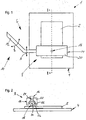
- Fig. 1 shows a schematic top view onto an apparatus 1 for treating substrates 2, while Fig. 2 shows a schematic sectional view of the apparatus 1 along the line I - I.
- the apparatus 1 basically consists of a receiver for the substrate, which will be called a substrate holder for an application unit 6.
- the substrate holder 4 and the application unit 6 may be arranged in a pressure chamber, which is not shown, in which a positive pressure or a negative pressure may be generated by appropriate means.
- the substrate holder 4 is, as may be seen in the drawings, a flat rectangular plate for receiving the also rectangular substrate 2.
- the substrate holder 4 may have other shapes, which may be matched to the shape of the substrate 2 to be treated.
- the substrate holder 4 has a drainage, which is not shown, for liquids, which may be applied via the application unit 6 onto the substrate 2.
- the application unit 6 consists of a main part 8 and a support part 10, which supports the main part 8 in a movable manner, as is shown by the double-headed arrows A and B.
- the support part 10 has a support arm 12, which is connected on one end to the main part 8, and the other end of which is connected to a drive, which is not shown.
- the drive may for example provide a pivotal movement of the support arm 10 and thus the main part 8 and/or a linear movement.
- the main part 8 may be moved across a substrate 2, which is received on said substrate holder 4, in order to enable treatment of partial areas or the complete surface of said substrate.
- the support arm 10 conducts a lift movement in order to adjust a distance between the main part 8 and the surface of a substrate 2 received on the substrate holder 4.
- the main part 8 consists in substance of a housing 14; a fluid port 16 and a radiation source 18.
- the housing 14 has an elongated cuboid shaped body 20, which defines in its longitudinal extension a flow chamber 22, which in substance extends across the complete lengths of the body 20.
- the flow chamber 22 has a length extension, which is larger than a width extension of the substrate 2, in order to be able to apply a liquid to the substrate across the complete width thereof, as will be explained in more detail herein below. It is also possible that the flow chamber has a smaller dimension.
- the inner surface of the flow chamber 22 is designed to have a high reflectivity in particular with respect to UV radiation, while IR radiation may be substantially absorbed.
- the flow chamber 20 has a substantially round cross-sectional shape.
- the flow chamber 22 is open towards the bottom side of the body 20, such that the body defines an outlet opening directed towards the substrate 2 to be treated.
- a conduit 24 is provided in the body 20, which extends in substance parallel to the flow chamber 22.
- the conduit 24 is fluidly connected to the flow chamber 22 at a plurality of locations, in order to conduct fluids into the flow chamber 22 via the conduit 24.
- the conduit 24 is capable of conducting fluids into the flow chamber 22 substantially over the complete length thereof.
- the conduit 24 is also connected to the fluid port 16.
- the fluid port 16 is connected to a conduit, not shown, via which one or more fluids may be conducted to the fluid port 16. It is possible, that a plurality of fluids may be simultaneously or sequentially conducted to the fluid port via this conduit. It is also possible to provide a plurality of conduits, via e.g. different fluids may be conducted to the fluid port. As fluids, e.g. liquids may be taken into consideration, but it is also possible to conduct gases to the fluid port, which may e.g. be mixed with a liquid in the fluid port 16 and the conduit 24, before they are conducted to the flow chamber 22. In Fig. 2 arrows are shown, which indicate the flow of a fluid from the fluid port 16 via the conduit 24, into the flow chamber 22 and out of the housing 14.
- the radiation source 18 has a longitudinally extending shape and extends along the complete flow chamber 22, substantially in the middle thereof.
- the radiation source 18 has a rod lamp 30, which is surrounded by a cover 32, which is substantially transparent to the radiation of a lamp 30.
- the rod lamp is of the type, which emits at least UV radiation in a predetermined range of wave length. It is also possible that the rod lamp 30 emits radiation across a broad spectrum of wave lengths and in particular emits UV radiation and IR radiation.
- the cover 32 which may consist for example of quartz glass surrounds the rod lamp 30 completely within the flow chamber 22 and isolates the same with respect to fluids in the flow chamber 22.
- the cover may for example extend through an end wall of the flow chamber 22 out of the body 20. This would enable access to the rod lamp 30, for example for replacement or maintenance purposes, without having to access the flow chamber 22.
- Due to its arrangement in the flow chamber 22, the cover 32 forms together with the inner walls of the flow chamber 22 a flow path for fluids conducted into the now chamber 22 via the conduit 24. Such fluids flow around the cover 32 and thus as a whole around the radiation source 18. Radiation emitted by the rod lamp 30 is thus introduced into any fluid flowing along the flow path.
- the cover 32 extends beyond the bottom surface of the body 20 and thus partially extends into an outlet opening of the body 20.
- radiation emitted from the rod lamp also exits the flow chamber 22 towards the substrate holder 4 or onto a substrate 2 thereon.
- the radiation may be introduced into a liquid film on the substrate 2, which is for example formed by a liquid, which flows through the flow chamber 22 onto the substrate.
- Fig. 3 shows a schematic side view similar to fig. 2 of an alternative embodiment of the apparatus 1 for treating substrates 2.
- the same reference signs are used as previously inasmuch as the same or similar elements are provided.
- the apparatus 1 again substantially consists of a substrate holder 4 for receiving a substrate and an application unit 6.
- the substrate holder may be designed in the same manner as described before with respect to figures 1 and 2 .
- the application unit 6 again consists of a main part 8 and a support part, which is not shown in Fig. 3 , which may, however, have the same design as previously described with respect to Figs. 1 and 2 .
- the main part 8 again substantially consists of a housing 14, a fluid port 16 and a radiation source 18, wherein the housing 14 and the fluid port may have the same design as previously described with respect to Figs. 1 and 2 .
- the radiation source 18 again has an elongated shape and extends substantial in the middle through the flow chamber 22.
- the radiation source 18 in this embodiment has rod lamps 30, 30', which are surrounded by a cover 32, which is substantially transparent to the radiation of the rod lamps 30, 30'.
- the rod lamps 30, 30' are shown above each other in Fig. 3 , but they may also be arranged in a different manner within the cover 32.
- the rod lamps may be of the same or of different types, wherein at least one of them emits UV radiation in a predetermined range of wave length. In particular, it is possible that both rod lamps 30, 30' emit UV radiation in different ranges of wave length.
- the upper rod lamp 30' may for example at least partially or primarily emit UV radiation in the wave length range above 180 nm, while the lower rod lamp 30 at least partially or primarily emits UV radiation in the wave length range of 140 to 280 nm, depending in on the liquid between 140 nm to 200 nm.
- One or both of the rod lamps 30, 30' may also emit an amount of IR radiation or other radiation.
- the cover 32 surrounds the rod lamps 30, 30' completely within the flow chamber 22 and isolates the same with respect to fluids in said flow chamber 22.
- the cover 32 may have the same design the cover previously described with respect to Figs. 1 and 2 .
- further rod lamps are received within the cover 32, which may each emit different radiation or also the same radiation.
- a desired radiation profile (with respect to emitted wave length and spatial distribution thereof) may be generated within the flow chamber 22 and beyond the same via the outlet opening of the body 20.
- Fig. 4 shows a schematic cross-sectional view similar to Fig. 2 of another alternative embodiment of an apparatus 1 for treating substrates 2.
- the same reference signs will be used as previously, inasmuch as the same or similar elements are provided.
- the apparatus 1 again substantially consists of a substrate holder 4 for receiving a substrate and an application unit 6.
- the substrate holder 4 may be designed in the same manner as previously described with respect to Figs. 1 and 2 .
- the application unit 6 again consists of a main part 8 a support part, which is not shown in Fig. 4 , but which may have the same design as one previously described with respect to Figs. 1 and 2 .
- the main part 8 again consists substantially of a housing 14, a fluid port 16 and a radiation source 18. Additionally, two further radiation sources 40 are provided.
- the housing 14 may have a similar design as the one previously described with respect two Figs. 1 and 2 , having an elongated cuboid body 20.
- a flow chamber 22 and a conduit 24 in the body 20 have the same design as the ones previously described with respect to Figs. 1 and 2 . This is also true with respect to the fluid port 16.
- recesses 42 are provided which extend along the length of the body on both sides of the outlet opening.
- the recesses are dimensioned to at least partially receive the further radiation sources 40.
- the surfaces of the recesses 42 may have a reflecting surface for the radiation of the radiation sources 40.
- the radiation source 18 may have the same design as one design as one described with respect to Figs. 1 and 2 or it may also have the design described with respect to Fig. 3 .
- the radiation sources 40 each comprise a rod lamp extending over the length of the body 20, which are received in the respective recesses 42 of the body 20. Even though this is not shown in Fig. 4 , the radiation sources 40 may each comprise a cover which is substantially transparent to the radiation of the rod lamp, which cover isolates the rod lamp with respect to the ambient, in particular with respect to any liquids exiting the flow chamber.
- the rod lamps of the radiation sources 40 may be of the same or a different type and they can also be of a different type to the rod lamps 30, 30' of the radiation source 18. Instead of providing two radiation sources 40, as shown in Fig. 4 , it is also possible to provide only one radiation source 40.
- Fig. 5 shows a schematic sectional view similar to Fig. 2 of a further embodiment of an apparatus 1 for treating substrates 2.
- the same reference signs are used as previously, inasmuch as the same or similar elements are provided.
- the apparatus 1 again consists substantially of a substrate holder 4, for receiving a substrate and an application unit 6.
- the substrate holder 4 may be designed in the same manner as previously described with respect to Figs. 1 and 2 .
- the application unit 6 again consists of a main part 8 and a support part, which is not shown in Fig. 5 .
- the main part 8 which will be described here in bellow is capable of completely covering the substrate, a movability of the support part may be dispensed with. Only a distance adjustment may be required, as well as a movability in order to position the substrate below the main part.
- the main part 8 consists in substance of a housing 14, a plurality of fluid ports 16 and a plurality of radiation sources 18.
- the housing consists of a body 20, which is matched to the shape of the substrate to be treated.
- a flow chamber 22 is formed, which is open to the bottom side of the body, wherein the opening corresponds in substance to the dimensions of the substrate to be treated.
- the inner walls of the flow chamber 22 are reflective.
- the upper side of the flow chamber 22 is connected via a plurality of conduits 24 to a plurality of fluid ports 16 (six are shown here).
- a plurality of radiation sources 18 (six are shown here) is provided within the flow chamber 22, which radiation sources extend in a longitudinal or transverse direction through the flow chamber 22. Thus, different flow paths are formed between the walls of the flow chamber 22 and radiation sources 18, as well as between the individual radiation sources.
- the radiation sources 18 may have the same design as the ones described with respect to Figs. 1 and 2 or as described with respect to Fig. 3 .
- the housing 14 has a similar design as the one previously described with respect to Figs. 1 and 2 , having an elongated cuboid shaped body 20, a flow chamber 22 and a conduit 24 in the body 20 have the same design, as previously described with respect to Figs. 1 and 2 . This is also true for fluid port 16.
- the rod lamps described above are each connected to a control unit, which is capable of controlling or driving the rod lamps individually and independently of the others. Rather than using rod lamps it is also possible to use other lamps/radiators which should, however, be capable of providing a substantially homogeneous radiation profile across the length of the flow chamber.
- the main part 8 of the application unit 6 will be moved over a substrate 2 on the substrate holder 4. If the complete surface of the substrate should be treated the main part 8 may be moved during the treatment described here in below across the substrate, unless the embodiment according to Fig. 5 is used, which may completely cover the substrate.
- a fluid in particular a liquid is applied to at least the surfaces of the substrate to be treated via the fluid ports 16, the conduits 24 and the flow chamber 22.
- Radiation is introduced into said fluid via the first radiation sources 18 and/or the radiation sources 40.
- the radiation is chosen such that it directly acts on the substrate, in order to treat the same and/or to act on the fluid for changing the characteristics thereof, in order to conduct the desired treatment. In so doing, different treatment possibilities for the surface of the substrate are given, which may be iocaiiy limited or may be conducted on the complete surface of the substrate.
- a liquid such as Dl water will be applied as a fluid via the flow chamber 22 onto the substrate surfaces to be treated, in order to form a liquid film on the substrate 2.
- UV radiation will be introduced into this liquid film via the radiation sources 18 or 40, wherein the liquid and the wave length range of the UV radiation are matched to each other, such that a substantial portion of the UV radiation reaches the interface between the liquid and the substrate surface.
- the UV radiation now acts to change the previously hydrophobic substrate surface to a hydrophilic surface.
- the wave length range of the UV radiation used here is for example above 190 nm.
- a corresponding rod lamp which emits in this wave length range, may be controlled or driven, while possibly other lamps are not controlled or driven.
- the sited wave length range one of the following may be used as the liquid: ozone-water, hydrogen-water, DI water or mixtures thereof. Other liquids may also be used.
- substrate surface was for example treated to have a hydrophilic surface as described above, and which has contaminations, which may be better removed by interaction with radicals.
- a liquid is applied to the surfaces of the substrate 2 to be cleaned via the flow chamber 22. While the liquid flows around the radiation source 18, UV radiation is emitted into the liquid by the radiation source 18. This radiation causes inter alia the generation of radicals in the liquid. This generation occurs directly before the liquid is applied to the substrate, such that at least a portion of the thus generated radicals, which have a very short decay time contact the substrate 2. Since a radiation of the radiation source 18 is not limited to the flow chamber 22, it is also introduced into a liquid film which is formed by the liquid on the substrate 2 and thus generates further radicals and/or partially maintains the activation of the already generated radicals.
- the liquid and the radiation introduced therein are again matched to each other in order to achieve the desired effect.
- UV radiation in the wave length range of 140 to 280 nm, depending in on the liquid between 140 nm to 200 nm is suited.
- the UV radiation in the cited wave length range may in particular be matched to the used liquid such that at least 50% of the UV radiation and in particular 80% thereof are absorbed.
- the generation of radicals may also be facilitated by a UV induced decomposition of the liquid, which may occur while the liquid flows around the radiation source 18.
- the UV radiation should be chosen on the one hand such that a destruction of the molecular structure of the liquid is caused, in order to facilitate a directly following generation of radicals also by means by UV radiation.
- UV radiation having a wave length above 180 nm is particularly suited for such decomposition.
- the upper rod lamp is one, which promotes the decomposition, i.e.
- the lower rod lamp is one, which promotes the generation of radicals, i.e. emits UV light having a wave length between 140 and 280 nm, depending in on the liquid between 140 nm to 200 nm.
- the wavelength range between 140 nm to 200 nm may be suited for the generation of radicals, while for other liquids, a higher range of wavelength between 140 nm to 280 nm may be suited.
- wave length ranges are obviously not binding and may vary depending on the liquid, but are applicable for many of the usually used liquids for cleaning photo masks such as: ozone-water, hydrogen-water, Dl water, H 2 O 2 , CO 2 -H 2 O, Dl water having O 2 -gas dissolved therein, NH 4 OH, organic acids, TMAH, HNO 3 , HCl, H 2 SO4 or mixtures thereof:
- a liquid which is heated above ambient temperature is applied via the flow chamber 22 onto the substrate, in order to form a liquid film on at least a partial area of the substrate 2.
- Radiation is introduced into this liquid film via at least one of the radiation sources 18, 40, wherein the radiation and the liquid are matched to each other, such that at least a portion of the radiation reaches the substrate surface.
- the electromagnetic radiation causes increased ion mobility, when it hits residual ions on the substrate surface.
- the radiation as long as it is absorbed in the liquid may also cause a temperature increase and/or the generation of radicals, which may both promote the removal of ions.
- the liquid many be heated directly during the application thereof, for example by means of radiation source having a high IR portion. Inasmuch as an increased temperature of the liquid also increases the solubility of the ions in the liquid, the liquid may be heated up to the boiling point thereof.
- liquid for example one of the following liquids may be used: ozone-water, hydrogen-water, Dl water, H 2 O 2 , CO 2 -H 2 O, Dl water having O 2 -gas dissolved therein, or mixtures thereof.
- Dl water is particularly suited for higher temperatures.
- the radiation in particular UV radiation in the wave length range above 190 nm is suited, which is not so strongly absorbed and which promotes the desired effect of mobilizing and removing ions.
- IR radiation is also well suited, inasmuch it may provide an in-situ heating of the liquid.
Landscapes
- Physics & Mathematics (AREA)
- Optics & Photonics (AREA)
- General Physics & Mathematics (AREA)
- Cleaning Or Drying Semiconductors (AREA)
- Physical Or Chemical Processes And Apparatus (AREA)
- Exposure Of Semiconductors, Excluding Electron Or Ion Beam Exposure (AREA)
- Cleaning By Liquid Or Steam (AREA)
- Physical Water Treatments (AREA)
Applications Claiming Priority (3)
| Application Number | Priority Date | Filing Date | Title |
|---|---|---|---|
| US25763309P | 2009-11-03 | 2009-11-03 | |
| DE102009058962A DE102009058962B4 (de) | 2009-11-03 | 2009-12-18 | Verfahren und Vorrichtung zum Behandeln von Substraten |
| PCT/EP2010/001629 WO2011054405A2 (en) | 2009-11-03 | 2010-03-15 | Method and apparatus for treating substrates |
Publications (2)
| Publication Number | Publication Date |
|---|---|
| EP2496367A2 EP2496367A2 (en) | 2012-09-12 |
| EP2496367B1 true EP2496367B1 (en) | 2016-02-10 |
Family
ID=43828929
Family Applications (1)
| Application Number | Title | Priority Date | Filing Date |
|---|---|---|---|
| EP10710543.9A Active EP2496367B1 (en) | 2009-11-03 | 2010-03-15 | Method and apparatus for treating substrates |
Country Status (9)
| Country | Link |
|---|---|
| US (3) | US9662684B2 (enExample) |
| EP (1) | EP2496367B1 (enExample) |
| JP (1) | JP5766197B2 (enExample) |
| KR (1) | KR20120101427A (enExample) |
| CN (1) | CN102791391B (enExample) |
| CA (1) | CA2778288C (enExample) |
| DE (1) | DE102009058962B4 (enExample) |
| SG (1) | SG10201407169UA (enExample) |
| WO (1) | WO2011054405A2 (enExample) |
Families Citing this family (29)
| Publication number | Priority date | Publication date | Assignee | Title |
|---|---|---|---|---|
| JP2013045961A (ja) * | 2011-08-25 | 2013-03-04 | Dainippon Screen Mfg Co Ltd | 基板洗浄方法、基板洗浄液および基板処理装置 |
| DE102012008220A1 (de) * | 2012-04-25 | 2013-10-31 | Süss Microtec Photomask Equipment Gmbh & Co. Kg | Verfahren zum Reinigen von Fotomasken unter Verwendung von Megaschall |
| US9339853B2 (en) | 2012-12-04 | 2016-05-17 | The Boeing Company | Surface materials for decontamination with decontaminants |
| US8764905B1 (en) * | 2013-03-14 | 2014-07-01 | Intel Corporation | Cleaning organic residues from EUV optics and masks |
| CN103691714B (zh) * | 2013-12-19 | 2015-12-02 | 合肥京东方光电科技有限公司 | 一种清洗装置和清洗方法 |
| US9857680B2 (en) | 2014-01-14 | 2018-01-02 | Taiwan Semiconductor Manufacturing Company, Ltd. | Cleaning module, cleaning apparatus and method of cleaning photomask |
| JP6357319B2 (ja) * | 2014-02-17 | 2018-07-11 | 株式会社プレテック | 被洗浄基板の洗浄方法及び洗浄装置 |
| CN104007610B (zh) * | 2014-06-12 | 2018-03-06 | 深圳市华星光电技术有限公司 | 掩模版的清洗方法及装置 |
| KR102296739B1 (ko) * | 2014-10-27 | 2021-09-01 | 삼성전자 주식회사 | 포토마스크용 세정 조성물을 이용한 집적회로 소자 제조 방법 |
| DE102015011177B4 (de) * | 2015-08-27 | 2017-09-14 | Süss Microtec Photomask Equipment Gmbh & Co. Kg | Vorrichtung zum Aufbringen eines mit UV-Strahlung beaufschlagten flüssigen Mediums auf ein Substrat |
| DE102015011228B4 (de) * | 2015-08-27 | 2017-06-14 | Süss Microtec Photomask Equipment Gmbh & Co. Kg | Vorrichtung zum Aufbringen eines mit UV-Strahlung beaufschlagten flüssigen Mediums auf ein Substrat |
| DE102015011229B4 (de) * | 2015-08-27 | 2020-07-23 | Süss Microtec Photomask Equipment Gmbh & Co. Kg | Vorrichtung zum Aufbringen eines mit UV-Strahlung beaufschlagten flüssigen Mediums auf ein Substrat |
| US11358172B2 (en) * | 2015-09-24 | 2022-06-14 | Suss Microtec Photomask Equipment Gmbh & Co. Kg | Method for treating substrates with an aqueous liquid medium exposed to UV-radiation |
| US9966266B2 (en) | 2016-04-25 | 2018-05-08 | United Microelectronics Corp. | Apparatus for semiconductor wafer treatment and semiconductor wafer treatment |
| KR101961326B1 (ko) | 2016-10-19 | 2019-07-18 | 세메스 주식회사 | 기판을 처리하는 장치의 부품 세정 방법 및 장치 |
| US10416575B2 (en) * | 2016-11-16 | 2019-09-17 | Suss Microtec Photomask Equipment Gmbh & Co. Kg | Apparatus and method for cleaning a partial area of a substrate |
| DE102017203351B4 (de) | 2017-03-01 | 2021-08-05 | Süss Microtec Photomask Equipment Gmbh & Co. Kg | Vorrichtung zum Aufbringen eines mit UV-Strahlung beaufschlagten flüssigen Mediums auf ein Substrat |
| JP2018163980A (ja) | 2017-03-24 | 2018-10-18 | 株式会社Screenホールディングス | 基板処理方法および基板処理装置 |
| JP2017113753A (ja) * | 2017-03-30 | 2017-06-29 | 株式会社トクヤマ | 洗浄方法および洗浄装置 |
| CN107203094B (zh) * | 2017-07-03 | 2020-07-24 | 京东方科技集团股份有限公司 | 掩膜版清理装置及方法 |
| CN108380569A (zh) * | 2018-03-02 | 2018-08-10 | 常州瑞择微电子科技有限公司 | 高浓度oh自由基发生装置 |
| CN108816870B (zh) * | 2018-04-08 | 2021-05-25 | 苏州珮凯科技有限公司 | 半导体8寸晶元制造薄膜制程的WxZ工艺的陶瓷环状零部件再生方法 |
| US12112959B2 (en) | 2018-09-04 | 2024-10-08 | Tokyo Electron Limited | Processing systems and platforms for roughness reduction of materials using illuminated etch solutions |
| US10896824B2 (en) * | 2018-12-14 | 2021-01-19 | Tokyo Electron Limited | Roughness reduction methods for materials using illuminated etch solutions |
| CN110112084A (zh) * | 2019-05-22 | 2019-08-09 | 长江存储科技有限责任公司 | 半导体器件清洗装置 |
| CN114072732A (zh) * | 2019-07-01 | 2022-02-18 | Asml荷兰有限公司 | 用于对图案化装置和其他衬底进行表面处理的表面处理设备和方法 |
| CN111906093A (zh) * | 2020-07-15 | 2020-11-10 | 常州瑞择微电子科技有限公司 | 一种大面积光子发生喷头 |
| CN112435938A (zh) * | 2020-11-11 | 2021-03-02 | 深圳市华星光电半导体显示技术有限公司 | 基板清洗设备及基板清洗方法 |
| US11798799B2 (en) * | 2021-08-09 | 2023-10-24 | Applied Materials, Inc. | Ultraviolet and ozone clean system |
Citations (1)
| Publication number | Priority date | Publication date | Assignee | Title |
|---|---|---|---|---|
| JP2008043925A (ja) * | 2006-08-21 | 2008-02-28 | Ushio Inc | エキシマランプ装置 |
Family Cites Families (19)
| Publication number | Priority date | Publication date | Assignee | Title |
|---|---|---|---|---|
| JP2623497B2 (ja) * | 1988-03-07 | 1997-06-25 | ウシオ電機株式会社 | オゾン水活性化装置 |
| US5068040A (en) * | 1989-04-03 | 1991-11-26 | Hughes Aircraft Company | Dense phase gas photochemical process for substrate treatment |
| JPH04277748A (ja) | 1991-03-06 | 1992-10-02 | Mitsubishi Paper Mills Ltd | 平版印刷版 |
| US5814156A (en) | 1993-09-08 | 1998-09-29 | Uvtech Systems Inc. | Photoreactive surface cleaning |
| US5789755A (en) | 1996-08-28 | 1998-08-04 | New Star Lasers, Inc. | Method and apparatus for removal of material utilizing near-blackbody radiator means |
| US6869487B1 (en) | 1997-05-09 | 2005-03-22 | Semitool, Inc. | Process and apparatus for treating a workpiece such as a semiconductor wafer |
| JPH11121417A (ja) * | 1997-10-09 | 1999-04-30 | Mitsubishi Electric Corp | 半導体基板の処理システムおよび処理方法 |
| NL1012389C1 (nl) * | 1999-06-18 | 2000-12-19 | Remmen Uv Techniek Van | Ultraviolette lamp en douchekop voorzien van een lamp. |
| DE10130999A1 (de) * | 2000-06-29 | 2002-04-18 | D M S Co | Multifunktions-Reinigungsmodul einer Herstellungseinrichtung für Flachbildschirme und Reinigungsgerät mit Verwendung desselben |
| JP2002110611A (ja) * | 2000-10-04 | 2002-04-12 | Texas Instr Japan Ltd | 半導体ウェハの洗浄方法及び装置 |
| JP4038557B2 (ja) | 2002-04-16 | 2008-01-30 | リアライズ・アドバンストテクノロジ株式会社 | レジスト除去装置及びレジスト除去方法 |
| JP3776092B2 (ja) * | 2003-03-25 | 2006-05-17 | 株式会社ルネサステクノロジ | エッチング装置、エッチング方法および半導体装置の製造方法 |
| US7921859B2 (en) | 2004-12-16 | 2011-04-12 | Sematech, Inc. | Method and apparatus for an in-situ ultraviolet cleaning tool |
| JP5140916B2 (ja) * | 2005-10-07 | 2013-02-13 | 富士通株式会社 | 光化学処理装置及び光化学処理方法 |
| US20070093406A1 (en) | 2005-10-24 | 2007-04-26 | Omoregie Henryson | Novel cleaning process for masks and mask blanks |
| JP2007149972A (ja) * | 2005-11-28 | 2007-06-14 | Matsushita Electric Ind Co Ltd | 電子デバイス洗浄装置および電子デバイス洗浄方法 |
| NL1030589C2 (nl) * | 2005-12-05 | 2007-06-06 | Houston R & D Consultancy B V | Werkwijze en systeem voor het reinigen van een lichaam en/of een fluïdum. |
| JP2008108997A (ja) * | 2006-10-27 | 2008-05-08 | Shibuya Kogyo Co Ltd | 洗浄装置 |
| WO2008107933A1 (ja) * | 2007-03-07 | 2008-09-12 | Fujitsu Limited | 洗浄装置および洗浄方法 |
-
2009
- 2009-12-18 DE DE102009058962A patent/DE102009058962B4/de active Active
-
2010
- 2010-03-15 EP EP10710543.9A patent/EP2496367B1/en active Active
- 2010-03-15 KR KR1020127014173A patent/KR20120101427A/ko not_active Ceased
- 2010-03-15 CN CN201080050483.6A patent/CN102791391B/zh active Active
- 2010-03-15 JP JP2012537306A patent/JP5766197B2/ja active Active
- 2010-03-15 CA CA2778288A patent/CA2778288C/en active Active
- 2010-03-15 US US13/505,385 patent/US9662684B2/en active Active
- 2010-03-15 WO PCT/EP2010/001629 patent/WO2011054405A2/en not_active Ceased
- 2010-03-15 SG SG10201407169UA patent/SG10201407169UA/en unknown
-
2017
- 2017-05-18 US US15/598,361 patent/US10265739B2/en active Active
- 2017-05-18 US US15/598,344 patent/US20170320108A1/en not_active Abandoned
Patent Citations (1)
| Publication number | Priority date | Publication date | Assignee | Title |
|---|---|---|---|---|
| JP2008043925A (ja) * | 2006-08-21 | 2008-02-28 | Ushio Inc | エキシマランプ装置 |
Also Published As
| Publication number | Publication date |
|---|---|
| US9662684B2 (en) | 2017-05-30 |
| US20170252781A1 (en) | 2017-09-07 |
| CN102791391A (zh) | 2012-11-21 |
| US10265739B2 (en) | 2019-04-23 |
| DE102009058962B4 (de) | 2012-12-27 |
| US20170320108A1 (en) | 2017-11-09 |
| WO2011054405A2 (en) | 2011-05-12 |
| EP2496367A2 (en) | 2012-09-12 |
| DE102009058962A1 (de) | 2011-05-05 |
| JP2013510332A (ja) | 2013-03-21 |
| US20120211024A1 (en) | 2012-08-23 |
| HK1175141A1 (zh) | 2013-06-28 |
| JP5766197B2 (ja) | 2015-08-19 |
| CN102791391B (zh) | 2016-05-25 |
| WO2011054405A3 (en) | 2012-06-28 |
| CA2778288A1 (en) | 2011-05-12 |
| CA2778288C (en) | 2016-01-19 |
| KR20120101427A (ko) | 2012-09-13 |
| SG10201407169UA (en) | 2014-12-30 |
Similar Documents
| Publication | Publication Date | Title |
|---|---|---|
| EP2496367B1 (en) | Method and apparatus for treating substrates | |
| JP2013510332A5 (enExample) | ||
| KR20010051163A (ko) | 자외광 조사장치 및 방법 | |
| JP6738414B2 (ja) | 紫外線に暴露された水性液体媒体で基板を処理する方法 | |
| KR20040105567A (ko) | 유기층 제거 방법 및 장치 | |
| JP4407252B2 (ja) | 処理装置 | |
| JP2001137800A (ja) | 基板処理装置及び処理方法 | |
| JP2001300451A (ja) | 紫外光照射装置 | |
| JP2009234815A (ja) | グラフェンシート系材料の処理方法及び装置 | |
| JP2002219429A (ja) | 基板処理装置及び処理方法 | |
| JP4286158B2 (ja) | オゾン処理装置 | |
| HK1175141B (en) | Method and apparatus for treating substrates | |
| JP2004152842A (ja) | 紫外光照射による処理方法および紫外光照射装置 | |
| JPH06210287A (ja) | 誘電体バリヤ放電ランプを使用した処理方法 | |
| JP4382190B2 (ja) | 基板の処理装置及び処理方法 | |
| JP7605675B2 (ja) | 基板処理方法 | |
| JP6447292B2 (ja) | 光処理装置 | |
| WO2020183920A1 (ja) | 基板処理方法および基板処理装置 | |
| JP3778210B2 (ja) | 誘電体バリヤ放電ランプを使用した処理方法 | |
| JP2017017070A (ja) | 光処理装置および光処理方法 | |
| JP2007227285A (ja) | プラズマ処理装置および方法 | |
| JP2005313174A (ja) | 誘電体バリヤ放電ランプを使用した処理方法 | |
| JP6459578B2 (ja) | 光処理装置および光処理方法 | |
| JP2016219656A (ja) | 光処理装置および光処理方法 | |
| JP2004031581A (ja) | 基板乾燥方法及び乾燥装置 |
Legal Events
| Date | Code | Title | Description |
|---|---|---|---|
| PUAI | Public reference made under article 153(3) epc to a published international application that has entered the european phase |
Free format text: ORIGINAL CODE: 0009012 |
|
| 17P | Request for examination filed |
Effective date: 20120503 |
|
| AK | Designated contracting states |
Kind code of ref document: A2 Designated state(s): AT BE BG CH CY CZ DE DK EE ES FI FR GB GR HR HU IE IS IT LI LT LU LV MC MK MT NL NO PL PT RO SE SI SK SM TR |
|
| RAP1 | Party data changed (applicant data changed or rights of an application transferred) |
Owner name: SUSS MICROTEC PHOTOMASK EQUIPMENT GMBH & CO. KG |
|
| DAX | Request for extension of the european patent (deleted) | ||
| 17Q | First examination report despatched |
Effective date: 20141217 |
|
| REG | Reference to a national code |
Ref country code: DE Ref legal event code: R079 Ref document number: 602010030528 Country of ref document: DE Free format text: PREVIOUS MAIN CLASS: B08B0007000000 Ipc: B08B0003100000 |
|
| RIC1 | Information provided on ipc code assigned before grant |
Ipc: B08B 7/00 20060101ALI20150605BHEP Ipc: B08B 3/10 20060101AFI20150605BHEP Ipc: G03F 1/82 20120101ALI20150605BHEP |
|
| GRAP | Despatch of communication of intention to grant a patent |
Free format text: ORIGINAL CODE: EPIDOSNIGR1 |
|
| INTG | Intention to grant announced |
Effective date: 20150724 |
|
| GRAS | Grant fee paid |
Free format text: ORIGINAL CODE: EPIDOSNIGR3 |
|
| GRAA | (expected) grant |
Free format text: ORIGINAL CODE: 0009210 |
|
| AK | Designated contracting states |
Kind code of ref document: B1 Designated state(s): AT BE BG CH CY CZ DE DK EE ES FI FR GB GR HR HU IE IS IT LI LT LU LV MC MK MT NL NO PL PT RO SE SI SK SM TR |
|
| REG | Reference to a national code |
Ref country code: GB Ref legal event code: FG4D |
|
| REG | Reference to a national code |
Ref country code: AT Ref legal event code: REF Ref document number: 774389 Country of ref document: AT Kind code of ref document: T Effective date: 20160215 Ref country code: CH Ref legal event code: EP |
|
| REG | Reference to a national code |
Ref country code: IE Ref legal event code: FG4D |
|
| REG | Reference to a national code |
Ref country code: FR Ref legal event code: PLFP Year of fee payment: 7 |
|
| REG | Reference to a national code |
Ref country code: DE Ref legal event code: R096 Ref document number: 602010030528 Country of ref document: DE |
|
| REG | Reference to a national code |
Ref country code: NL Ref legal event code: FP |
|
| REG | Reference to a national code |
Ref country code: LT Ref legal event code: MG4D |
|
| PG25 | Lapsed in a contracting state [announced via postgrant information from national office to epo] |
Ref country code: FI Free format text: LAPSE BECAUSE OF FAILURE TO SUBMIT A TRANSLATION OF THE DESCRIPTION OR TO PAY THE FEE WITHIN THE PRESCRIBED TIME-LIMIT Effective date: 20160210 Ref country code: GR Free format text: LAPSE BECAUSE OF FAILURE TO SUBMIT A TRANSLATION OF THE DESCRIPTION OR TO PAY THE FEE WITHIN THE PRESCRIBED TIME-LIMIT Effective date: 20160511 Ref country code: ES Free format text: LAPSE BECAUSE OF FAILURE TO SUBMIT A TRANSLATION OF THE DESCRIPTION OR TO PAY THE FEE WITHIN THE PRESCRIBED TIME-LIMIT Effective date: 20160210 Ref country code: NO Free format text: LAPSE BECAUSE OF FAILURE TO SUBMIT A TRANSLATION OF THE DESCRIPTION OR TO PAY THE FEE WITHIN THE PRESCRIBED TIME-LIMIT Effective date: 20160510 Ref country code: HR Free format text: LAPSE BECAUSE OF FAILURE TO SUBMIT A TRANSLATION OF THE DESCRIPTION OR TO PAY THE FEE WITHIN THE PRESCRIBED TIME-LIMIT Effective date: 20160210 Ref country code: IT Free format text: LAPSE BECAUSE OF FAILURE TO SUBMIT A TRANSLATION OF THE DESCRIPTION OR TO PAY THE FEE WITHIN THE PRESCRIBED TIME-LIMIT Effective date: 20160210 |
|
| PG25 | Lapsed in a contracting state [announced via postgrant information from national office to epo] |
Ref country code: IS Free format text: LAPSE BECAUSE OF FAILURE TO SUBMIT A TRANSLATION OF THE DESCRIPTION OR TO PAY THE FEE WITHIN THE PRESCRIBED TIME-LIMIT Effective date: 20160610 Ref country code: LV Free format text: LAPSE BECAUSE OF FAILURE TO SUBMIT A TRANSLATION OF THE DESCRIPTION OR TO PAY THE FEE WITHIN THE PRESCRIBED TIME-LIMIT Effective date: 20160210 Ref country code: PL Free format text: LAPSE BECAUSE OF FAILURE TO SUBMIT A TRANSLATION OF THE DESCRIPTION OR TO PAY THE FEE WITHIN THE PRESCRIBED TIME-LIMIT Effective date: 20160210 Ref country code: LT Free format text: LAPSE BECAUSE OF FAILURE TO SUBMIT A TRANSLATION OF THE DESCRIPTION OR TO PAY THE FEE WITHIN THE PRESCRIBED TIME-LIMIT Effective date: 20160210 Ref country code: BE Free format text: LAPSE BECAUSE OF NON-PAYMENT OF DUE FEES Effective date: 20160331 Ref country code: PT Free format text: LAPSE BECAUSE OF FAILURE TO SUBMIT A TRANSLATION OF THE DESCRIPTION OR TO PAY THE FEE WITHIN THE PRESCRIBED TIME-LIMIT Effective date: 20160613 Ref country code: SE Free format text: LAPSE BECAUSE OF FAILURE TO SUBMIT A TRANSLATION OF THE DESCRIPTION OR TO PAY THE FEE WITHIN THE PRESCRIBED TIME-LIMIT Effective date: 20160210 |
|
| PG25 | Lapsed in a contracting state [announced via postgrant information from national office to epo] |
Ref country code: DK Free format text: LAPSE BECAUSE OF FAILURE TO SUBMIT A TRANSLATION OF THE DESCRIPTION OR TO PAY THE FEE WITHIN THE PRESCRIBED TIME-LIMIT Effective date: 20160210 Ref country code: EE Free format text: LAPSE BECAUSE OF FAILURE TO SUBMIT A TRANSLATION OF THE DESCRIPTION OR TO PAY THE FEE WITHIN THE PRESCRIBED TIME-LIMIT Effective date: 20160210 |
|
| REG | Reference to a national code |
Ref country code: CH Ref legal event code: PL |
|
| REG | Reference to a national code |
Ref country code: DE Ref legal event code: R097 Ref document number: 602010030528 Country of ref document: DE |
|
| PG25 | Lapsed in a contracting state [announced via postgrant information from national office to epo] |
Ref country code: SM Free format text: LAPSE BECAUSE OF FAILURE TO SUBMIT A TRANSLATION OF THE DESCRIPTION OR TO PAY THE FEE WITHIN THE PRESCRIBED TIME-LIMIT Effective date: 20160210 Ref country code: CZ Free format text: LAPSE BECAUSE OF FAILURE TO SUBMIT A TRANSLATION OF THE DESCRIPTION OR TO PAY THE FEE WITHIN THE PRESCRIBED TIME-LIMIT Effective date: 20160210 Ref country code: SK Free format text: LAPSE BECAUSE OF FAILURE TO SUBMIT A TRANSLATION OF THE DESCRIPTION OR TO PAY THE FEE WITHIN THE PRESCRIBED TIME-LIMIT Effective date: 20160210 Ref country code: RO Free format text: LAPSE BECAUSE OF FAILURE TO SUBMIT A TRANSLATION OF THE DESCRIPTION OR TO PAY THE FEE WITHIN THE PRESCRIBED TIME-LIMIT Effective date: 20160210 |
|
| PLBE | No opposition filed within time limit |
Free format text: ORIGINAL CODE: 0009261 |
|
| STAA | Information on the status of an ep patent application or granted ep patent |
Free format text: STATUS: NO OPPOSITION FILED WITHIN TIME LIMIT |
|
| REG | Reference to a national code |
Ref country code: IE Ref legal event code: MM4A |
|
| PG25 | Lapsed in a contracting state [announced via postgrant information from national office to epo] |
Ref country code: BE Free format text: LAPSE BECAUSE OF FAILURE TO SUBMIT A TRANSLATION OF THE DESCRIPTION OR TO PAY THE FEE WITHIN THE PRESCRIBED TIME-LIMIT Effective date: 20160210 |
|
| 26N | No opposition filed |
Effective date: 20161111 |
|
| PG25 | Lapsed in a contracting state [announced via postgrant information from national office to epo] |
Ref country code: CH Free format text: LAPSE BECAUSE OF NON-PAYMENT OF DUE FEES Effective date: 20160331 Ref country code: LI Free format text: LAPSE BECAUSE OF NON-PAYMENT OF DUE FEES Effective date: 20160331 Ref country code: IE Free format text: LAPSE BECAUSE OF NON-PAYMENT OF DUE FEES Effective date: 20160315 |
|
| PG25 | Lapsed in a contracting state [announced via postgrant information from national office to epo] |
Ref country code: BG Free format text: LAPSE BECAUSE OF FAILURE TO SUBMIT A TRANSLATION OF THE DESCRIPTION OR TO PAY THE FEE WITHIN THE PRESCRIBED TIME-LIMIT Effective date: 20160510 Ref country code: SI Free format text: LAPSE BECAUSE OF FAILURE TO SUBMIT A TRANSLATION OF THE DESCRIPTION OR TO PAY THE FEE WITHIN THE PRESCRIBED TIME-LIMIT Effective date: 20160210 |
|
| REG | Reference to a national code |
Ref country code: FR Ref legal event code: PLFP Year of fee payment: 8 |
|
| PG25 | Lapsed in a contracting state [announced via postgrant information from national office to epo] |
Ref country code: MT Free format text: LAPSE BECAUSE OF FAILURE TO SUBMIT A TRANSLATION OF THE DESCRIPTION OR TO PAY THE FEE WITHIN THE PRESCRIBED TIME-LIMIT Effective date: 20160210 |
|
| REG | Reference to a national code |
Ref country code: FR Ref legal event code: PLFP Year of fee payment: 9 |
|
| PG25 | Lapsed in a contracting state [announced via postgrant information from national office to epo] |
Ref country code: CY Free format text: LAPSE BECAUSE OF FAILURE TO SUBMIT A TRANSLATION OF THE DESCRIPTION OR TO PAY THE FEE WITHIN THE PRESCRIBED TIME-LIMIT Effective date: 20160210 Ref country code: HU Free format text: LAPSE BECAUSE OF FAILURE TO SUBMIT A TRANSLATION OF THE DESCRIPTION OR TO PAY THE FEE WITHIN THE PRESCRIBED TIME-LIMIT; INVALID AB INITIO Effective date: 20100315 |
|
| PG25 | Lapsed in a contracting state [announced via postgrant information from national office to epo] |
Ref country code: MK Free format text: LAPSE BECAUSE OF FAILURE TO SUBMIT A TRANSLATION OF THE DESCRIPTION OR TO PAY THE FEE WITHIN THE PRESCRIBED TIME-LIMIT Effective date: 20160210 Ref country code: MT Free format text: LAPSE BECAUSE OF FAILURE TO SUBMIT A TRANSLATION OF THE DESCRIPTION OR TO PAY THE FEE WITHIN THE PRESCRIBED TIME-LIMIT Effective date: 20160331 Ref country code: MC Free format text: LAPSE BECAUSE OF FAILURE TO SUBMIT A TRANSLATION OF THE DESCRIPTION OR TO PAY THE FEE WITHIN THE PRESCRIBED TIME-LIMIT Effective date: 20160210 Ref country code: TR Free format text: LAPSE BECAUSE OF FAILURE TO SUBMIT A TRANSLATION OF THE DESCRIPTION OR TO PAY THE FEE WITHIN THE PRESCRIBED TIME-LIMIT Effective date: 20160210 Ref country code: LU Free format text: LAPSE BECAUSE OF NON-PAYMENT OF DUE FEES Effective date: 20160315 |
|
| REG | Reference to a national code |
Ref country code: AT Ref legal event code: UEP Ref document number: 774389 Country of ref document: AT Kind code of ref document: T Effective date: 20160210 |
|
| PGFP | Annual fee paid to national office [announced via postgrant information from national office to epo] |
Ref country code: GB Payment date: 20260324 Year of fee payment: 17 |
|
| PGFP | Annual fee paid to national office [announced via postgrant information from national office to epo] |
Ref country code: DE Payment date: 20260319 Year of fee payment: 17 |
|
| PGFP | Annual fee paid to national office [announced via postgrant information from national office to epo] |
Ref country code: AT Payment date: 20260320 Year of fee payment: 17 |
|
| PGFP | Annual fee paid to national office [announced via postgrant information from national office to epo] |
Ref country code: NL Payment date: 20260319 Year of fee payment: 17 |
|
| PGFP | Annual fee paid to national office [announced via postgrant information from national office to epo] |
Ref country code: FR Payment date: 20260320 Year of fee payment: 17 |