EP2489847A2 - Véhicule à selle - Google Patents
Véhicule à selle Download PDFInfo
- Publication number
- EP2489847A2 EP2489847A2 EP12152725A EP12152725A EP2489847A2 EP 2489847 A2 EP2489847 A2 EP 2489847A2 EP 12152725 A EP12152725 A EP 12152725A EP 12152725 A EP12152725 A EP 12152725A EP 2489847 A2 EP2489847 A2 EP 2489847A2
- Authority
- EP
- European Patent Office
- Prior art keywords
- vehicle
- sensor
- engine
- body frame
- exhaust pipe
- Prior art date
- Legal status (The legal status is an assumption and is not a legal conclusion. Google has not performed a legal analysis and makes no representation as to the accuracy of the status listed.)
- Granted
Links
- QVGXLLKOCUKJST-UHFFFAOYSA-N atomic oxygen Chemical compound [O] QVGXLLKOCUKJST-UHFFFAOYSA-N 0.000 claims abstract description 42
- 239000001301 oxygen Substances 0.000 claims abstract description 42
- 229910052760 oxygen Inorganic materials 0.000 claims abstract description 42
- 230000005855 radiation Effects 0.000 claims description 8
- 239000007789 gas Substances 0.000 claims description 6
- 239000003054 catalyst Substances 0.000 description 11
- 239000002828 fuel tank Substances 0.000 description 4
- 238000003780 insertion Methods 0.000 description 3
- 230000037431 insertion Effects 0.000 description 3
- 238000010561 standard procedure Methods 0.000 description 3
- 239000006096 absorbing agent Substances 0.000 description 2
- 238000010586 diagram Methods 0.000 description 2
- 239000000446 fuel Substances 0.000 description 2
- 230000035939 shock Effects 0.000 description 2
- 238000004381 surface treatment Methods 0.000 description 2
- 238000011144 upstream manufacturing Methods 0.000 description 2
- 230000001154 acute effect Effects 0.000 description 1
- 229910003460 diamond Inorganic materials 0.000 description 1
- 239000010432 diamond Substances 0.000 description 1
- 238000012423 maintenance Methods 0.000 description 1
- 239000000463 material Substances 0.000 description 1
- 239000002184 metal Substances 0.000 description 1
- 238000000034 method Methods 0.000 description 1
- 239000000203 mixture Substances 0.000 description 1
Images


Classifications
-
- F—MECHANICAL ENGINEERING; LIGHTING; HEATING; WEAPONS; BLASTING
- F01—MACHINES OR ENGINES IN GENERAL; ENGINE PLANTS IN GENERAL; STEAM ENGINES
- F01N—GAS-FLOW SILENCERS OR EXHAUST APPARATUS FOR MACHINES OR ENGINES IN GENERAL; GAS-FLOW SILENCERS OR EXHAUST APPARATUS FOR INTERNAL COMBUSTION ENGINES
- F01N13/00—Exhaust or silencing apparatus characterised by constructional features ; Exhaust or silencing apparatus, or parts thereof, having pertinent characteristics not provided for in, or of interest apart from, groups F01N1/00 - F01N5/00, F01N9/00, F01N11/00
- F01N13/008—Mounting or arrangement of exhaust sensors in or on exhaust apparatus
-
- F—MECHANICAL ENGINEERING; LIGHTING; HEATING; WEAPONS; BLASTING
- F01—MACHINES OR ENGINES IN GENERAL; ENGINE PLANTS IN GENERAL; STEAM ENGINES
- F01N—GAS-FLOW SILENCERS OR EXHAUST APPARATUS FOR MACHINES OR ENGINES IN GENERAL; GAS-FLOW SILENCERS OR EXHAUST APPARATUS FOR INTERNAL COMBUSTION ENGINES
- F01N13/00—Exhaust or silencing apparatus characterised by constructional features ; Exhaust or silencing apparatus, or parts thereof, having pertinent characteristics not provided for in, or of interest apart from, groups F01N1/00 - F01N5/00, F01N9/00, F01N11/00
- F01N13/18—Construction facilitating manufacture, assembly, or disassembly
- F01N13/1805—Fixing exhaust manifolds, exhaust pipes or pipe sections to each other, to engine or to vehicle body
- F01N13/1811—Fixing exhaust manifolds, exhaust pipes or pipe sections to each other, to engine or to vehicle body with means permitting relative movement, e.g. compensation of thermal expansion or vibration
- F01N13/1822—Fixing exhaust manifolds, exhaust pipes or pipe sections to each other, to engine or to vehicle body with means permitting relative movement, e.g. compensation of thermal expansion or vibration for fixing exhaust pipes or devices to vehicle body
-
- F—MECHANICAL ENGINEERING; LIGHTING; HEATING; WEAPONS; BLASTING
- F01—MACHINES OR ENGINES IN GENERAL; ENGINE PLANTS IN GENERAL; STEAM ENGINES
- F01N—GAS-FLOW SILENCERS OR EXHAUST APPARATUS FOR MACHINES OR ENGINES IN GENERAL; GAS-FLOW SILENCERS OR EXHAUST APPARATUS FOR INTERNAL COMBUSTION ENGINES
- F01N2560/00—Exhaust systems with means for detecting or measuring exhaust gas components or characteristics
- F01N2560/02—Exhaust systems with means for detecting or measuring exhaust gas components or characteristics the means being an exhaust gas sensor
- F01N2560/025—Exhaust systems with means for detecting or measuring exhaust gas components or characteristics the means being an exhaust gas sensor for measuring or detecting O2, e.g. lambda sensors
-
- F—MECHANICAL ENGINEERING; LIGHTING; HEATING; WEAPONS; BLASTING
- F01—MACHINES OR ENGINES IN GENERAL; ENGINE PLANTS IN GENERAL; STEAM ENGINES
- F01N—GAS-FLOW SILENCERS OR EXHAUST APPARATUS FOR MACHINES OR ENGINES IN GENERAL; GAS-FLOW SILENCERS OR EXHAUST APPARATUS FOR INTERNAL COMBUSTION ENGINES
- F01N2590/00—Exhaust or silencing apparatus adapted to particular use, e.g. for military applications, airplanes, submarines
- F01N2590/04—Exhaust or silencing apparatus adapted to particular use, e.g. for military applications, airplanes, submarines for motorcycles
Definitions
- the present invention relates to a saddle-ride type vehicle such as a motorcycle, and relates particularly to an earth structure for an oxygen sensor provided in an exhaust system of the saddle-ride type vehicle.
- an oxygen sensor is attached to an exhaust port of a cylinder head (see Japanese Patent Application Publication No. 2010-7645 ).
- An electrical component can be earthed in the following way.
- An engine-side earth wire is connected in advance from an engine to a battery, as an earth wire for other electrical equipment.
- the electrical component is earthed through the engine, together with the other electrical equipment, even with no earth wire specifically provided for the electrical component.
- the oxygen sensor When the conventional configuration with the oxygen sensor provided in the exhaust port is applied to a multi-cylinder engine, as many oxygen sensors as cylinders are required. It would be desirable to reduce the number of oxygen sensors to be used, and in order to achieve this, the oxygen sensor can be attached to a converging portion of an exhaust system. However, when only the oxygen sensor with no earth wire is desired to be provided, earthing needs to be achieved by a method different from the, conventional example.
- the exhaust pipe is fastened to a cylinder head of the engine via a gasket by using stud bolts and nuts.
- conductivity can be ensured by subjecting the gasket and the stud bolts to a special surface treatment.
- conductivity between the exhaust pipe and the engine is generally not ensured, and so it is difficult to employ an earth circuit from the exhaust pipe to the engine.
- such consideration is required not only for the multi-cylinder engine but also for a single-cylinder engine if the oxygen sensor is attached to the exhaust pipe.
- a saddle-ride type vehicle including a vehicle-body frame; an engine supported by the vehicle-body frame to be in electrical contact therewith; an exhaust pipe connected to the engine and supported by the vehicle-body frame at a position rearward of the engine; an oxygen sensor for measuring an oxygen amount in an exhaust gas; and a battery for supplying electric power to the oxygen sensor, the oxygen sensor and a positive electrode of the battery being connected to each other by an electric power wire, the engine and a negative electrode of the battery being connected to each other by an engine-side earth wire, wherein the oxygen sensor is attached to the exhaust pipe, an earth connection portion is provided near a support portion of the exhaust pipe with the vehicle-body frame, and the earth connection portion and the vehicle-body frame are connected to each other by a sensor-side earth wire different from the engine-side earth wire.
- the exhaust pipe and the vehicle-body frame can be used as part of the earth circuit when the oxygen sensor is attached to the exhaust pipe, and an earth wire directly connecting the oxygen sensor and the battery is omitted (in contrast to the configuration where the positive electrode of the battery and the oxygen sensor are connected to each other by the electric power wire and the negative electrode of the battery and the engine are connected to each other in advance).
- an earth circuit from the exhaust pipe, through the engine, through the earth connection portion, through the sensor-side earth wire, through the vehicle-body frame, through the engine, through the engine-side earth wire, and to the negative electrode of the battery can be employed instead of an earth circuit from the exhaust pipe to the engine.
- the length of the sensor-side earth wire connecting the exhaust pipe and the vehicle-body frame to each other can be made shorter than the case where an earth wire directly connecting the oxygen sensor and the battery is provided.
- the exhaust pipe includes a vehicle-body attachment stay to be attached to the vehicle-body frame, the earth connection portion is provided in the vehicle-body attachment stay, and one end of the sensor-side earth wire is connected to the earth connection portion while the other end thereof is connected to the vehic4e-bocly frame.
- connection of the sensor-side earth wire can be performed together with the work of attaching the exhaust pipe to the vehicle body by connecting one end of the sensor-side earth wire to the earth connection portion and connecting the other end thereof to the vehicle-body frame.
- the saddle-ride type vehicle includes a swing arm swingably and pivotally supporting a rear wheel, and a pivot plate pivotally supporting the swing arm and being part of the vehicle-body frame; the vehicle-body attachment stay is arranged below the pivot plate; and the other end of the sensor-side earth wire is connected to an inner side of the pivot plate in the direction of width of the vehicle.
- the sensor-side earth wire can be provided at a lower and less visible position.
- the other end of the sensor-side earth wire is attached to the vehicle-body frame in advance while the one end is left hanging down, before assembling the exhaust pipe and the vehicle-body frame by the attachment of the vehicle-body attachment stay to the vehicle-body frame.
- the one end of the sensor-side earth wire hanging down near the vehicle-body attachment stay is only required to be connected to the earth connection portion. Hence, the assemblability is improved.
- the oxygen sensor includes a washer interposed in a connection portion between the oxygen sensor and the exhaust pipe, and a heat radiation portion protruding outward from a portion attached with the exhaust pipe in a flared manner is formed integrally with the washer.
- the heat radiation characteristic of the oxygen sensor can be improved by use of the washer.
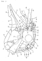
- a vehicle-body frame 10 includes a head pipe 11 at its front end, main frames 12 which branch respectively to the right and left from the head pipe 11 and extend rearward, a pair of right and left down frames 13 which extend obliquely downward toward the rear from a portion near a front portion of the main frames 12 which is rearward of the head pipe 11 and in front of the main frames 12, a pair of right and left seat rails 14 which extend obliquely upward and then extend rearward in a portion rearward of the main frames 12, and a pair of right and left pivot plates 15 which connect rear end portions of the main frames 12 to front end portions of the seat rails 14, respectively, and which extend obliquely downward toward the front.
- a front fork supporting a front wheel (neither of which are shown) at its lower end is turnably supported by the head pipe 11.
- An air cleaner 20 and a centre housing box 21 are supported on the main frames 12.
- An upper opening of the centre housing box 21 can be opened and closed by a centre lid 22.
- a fuel tank 23 is supported on the seat rails 14.
- a seat 24 is supported on the fuel tank 23.
- a rear portion of the seat 24 is a pillion seat 25 which is openable and closeable. Refuelling can be performed by opening the pillion seat 25 to the front and removing a fuel cap provided in a rear portion of the fuel tank 23.
- Step holders 27 are disposed below the seat 24, and each step holder is provided with a step 26 for a rider (driver) in a lower portion of a section overlapping with the pivot plates 15.
- a pillion step 28 for a pillion passenger is provided in a rear end portion of each step holder 27.
- the step holders 27 are attached to the respective pivot plates 15 in such a way that front portions of the step holders 27 cover the outer surfaces of the pivot plates 15.
- Right and left step holders 27 are provided as a pair.
- An engine 30 is disposed below the main frames 12.
- An upper portion of the engine 30 is supported by the main frames 12, a front portion thereof is supported by the down frames 13, and a rear portion thereof is supported by the pivot plates 15.
- the vehicle-body frame 10 uses the engine 30 as part of a frame structure, and thus configured to have a diamond structure.
- the engine 30 is supported by being fastened to the vehicle-body frame 10 by using bolts, and thus, the engine 30 and the vehicle-body frame 10 can be connected to each other so as to be electrically conductive to form an earth circuit.
- the engine 30 includes a crankcase 31 and a cylinder 32.
- the cylinder 32 includes a cylinder block 32a, a cylinder head 32b, and a head cover 32c.
- a mixture of air and fuel is supplied to the cylinder head 32b from the air cleaner 20 and the fuel tank 23, and an exhaust gas is exhausted through an exhaust pipe 33.
- the exhaust pipe 33 protrudes frontward of the cylinder head 32b and then extends rearward to be connected to a muffler 34.
- a front end of a swing arm 35 is swingably supported by the pivot plates 15 by use of a pivot 16.
- a rear wheel 36 is supported by the rear end of the swing arm 35, and is driven by the engine 30 via a chain (not shown).
- Reference numeral 37 indicates a shock absorber. An upper end of the shock absorber 37 is supported by the vehicle-body frame, and a lower end portion thereof is attached to a link mechanism provided between the swing arm 35 and the pivot plates 15.
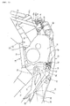
- Fig. 2 is a side view showing a portion including the pivot plate 15 on the right side of the motorcycle and the engine 30.
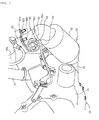
- Fig. 3 is a view showing a front portion of the engine 30 around a connection portion of the exhaust pipe 33.
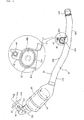
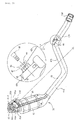
- Fig. 4 is a side view of an exhaust system component including the exhaust pipe 33 and the muffler 34.
- Fig. 5 is a plan view of the exhaust system component.
- Fig. 6 is a cross-sectional view taken along the line 6-6 of Fig. 4 .
- Fig. 7 is a view showing the pivot plate 15 on the right side of the motorcycle from the inner side of the motorcycle body (from the centre of the motorcycle body).
- Fig. 8 is a cross-sectional view taken along the 8-8 line of Fig. 7 .
- a front end portion of the exhaust pipe 33 is connected to an exhaust port 40 of the cylinder head 32b.
- the exhaust pipe 33 protrudes downward from the cylinder head 32b, runs in front of the crankcase 31, extends rearward while curving toward the left side of the lower portion of the crankcase 31, protrudes out to the right side of the vehicle body from the rear of the crankcase 31, runs below the pivot plate 15, and is connected to the muffler 34 at a position rearward of the pivot plate 15 and forward of the rear wheel 36.
- a vehicle-body attachment stay 46 is provided on a portion of the exhaust pipe 33 near the pivot plate 15, and is supported in a vibration-proof manner by an exhaust pipe support protrusion 17 provided at a lower end of the pivot plate 15.
- the muffler 34 is supported facing a side surface of the rear wheel 36 to be inclined upward toward the rear.
- a joint portion 41 provided in the front end portion of the exhaust pipe 33 is attached to the exhaust port 40 of the cylinder head 32b.
- An O 2 sensor 50 being an oxygen sensor is attached to a side surface on the inner side of the joint portion 41.
- the O 2 sensor 50 is an electric component, and electric power is supplied thereto from a battery (to be described later) using a harness.
- the O 2 sensor 50 uses the exhaust pipe 33, the vehicle-body frame 10, and the like as an earth.
- the joint portion 41 of the exhaust pipe 33 is connected to a catalyst pipe 42 on the downstream side.
- the catalyst pipe 42 is disposed to be inclined downward toward the rear, and to spread outward.
- the catalyst pipe 42 is arranged below the cylinder 32 forward of the crankcase 31.
- a front end portion (upstream end portion) of the catalyst pipe 42 is located near the O 2 sensor 50.
- the exhaust pipe 33 is formed of the joint portion 41, the catalyst pipe 42, and a rear portion pipe 43 arranged in this order from upstream.
- the joint portion 41 includes a mouth collar 41 a fitted to the exhaust port 40, a joint flange 41 b used for supplying to the exhaust port 40, and a mouth pipe 41c connected to the catalyst pipe 42.
- a sensor attachment nut 44 is provided in a side surface of the mouth pipe 41c on the vehicle-body inner side.
- the O 2 sensor 50 is detachably attached to the sensor attachment nut 44 (see Fig. 3 ).
- the catalyst pipe 42 has a larger diameter than the joint portion 41 and the rear portion pipe 43, and has a cylindrical shape obtained by combining half bodies, which have a semi-circular cross section and are press-formed from plate materials, to face each other.
- a publicly-known catalyst 45 is held inside the catalyst pipe 42.
- a front portion of the catalyst pipe 42 is formed into a neck portion 42a with a small diameter.
- a lower end portion of the mouth pipe 41c is connected to the neck portion 42a from above.
- the mouth pipe 41c and the neck portion 42a together are curved to have an almost L-shape in a side view.
- the exhaust gas purified by the catalyst 45 flows through the rear portion pipe 43 and is sent to the muffler 34.
- a rear end portion 43d of the rear portion pipe 43 is connected to a front end portion of the muffler 34.
- the rear portion pipe 43 is curved to the right and left with respect to a vehicle-body centre line CL, and includes a front section 43a disposed on the left side of the vehicle body, a crossing section 43b obliquely extending from the left side of the vehicle body to the right side thereof in a centre portion of the rear portion pipe 43, and a rear section 43c disposed on the right side of the vehicle body in a rear portion of the rear portion pipe 43.
- a rear end portion 43d of the rear section 43c is connected to the front end portion of the muffler 34.
- the vehicle-body attachment stay 46 which forms an attachment portion used to allow the exhaust pipe 33 to be supported by the vehicle body frame, is welded to an upper surface of the rear section 43c in a portion near a curved portion curved from the crossing section 43b.
- the vehicle-body attachment stay 46 has an almost semi-circular arc shape protruding upward in the side view, and a collar 46a is provided on the inner side.
- the vehicle-body attachment stay 46 is supported at the collar 46a in a vibration-proof manner by the exhaust pipe support protrusion 17 (see Fig. 2 ) provided in the lower end portion of the right pivot plate 15 via a rubber mount 46b.
- an earth connection portion 47 formed in a cut-and-lifted manner to protrude upward is provided integrally with an upper portion of the vehicle-body attachment stay 46.
- the earth connection portion 47 is provided with a bolt insertion hole, and a nut 48 is welded coaxially with the bolt insertion hole.
- the earth connection portion 47 and the nut 48 are electrically connected to an earth portion of the O 2 sensor 50 via the vehicle-body attachment stay 46 and the exhaust pipe 33, and are part of the earth circuit.
- a terminal 61 of a sensor-side earth wire 60 (see Fig. 7 ) is overlapped with the earth connection portion 47, and is fixed by fastening a bolt 49 to the nut 48 from the outer side of the vehicle body (here, the right side).
- the exhaust pipe 33 is electrically connected to the sensor side earth wire 60 via the earth connection portion 47.
- the joint portion 41 has a hollow pipe shape, and one end portion of the sensor attachment nut 44 is fitted and welded to a through hole provided in a side surface of the mouth pipe 41 c.
- an end of the O 2 sensor 50 is inserted in an exhaust passage 41e being an internal space, and an oxygen (O 2 ) amount in the exhaust passage 41e is measured.
- the mouth collar 41 a is fitted to an exhaust-pipe attachment portion 40a formed in an opening edge portion of the exhaust port 40 in the side surface of the cylinder head 32b in a protruding manner, and nuts 40c are fastened to through holes 41 d provided in the joint flange 41 b via stud bolts 40b protruding from the exhaust-pipe attachment portion 40a, respectively.
- the joint portion 41 is attached to an exhaust-pipe attachment portion 40a.
- a gasket 40e is interposed between an end of the mouth collar 41 a and a bottom portion of a fitting recess portion 40d which is provided in the exhaust-pipe attachment portion 40a and to which the mouth collar 41 a is fitted.
- the gasket 40e is illustrated with slightly reduced size to make it more visible, and the bottom portion of the fitting recess portion 40d and the end of the mouth collar 41 a are apart from each other. However, in reality, they are in tight contact with each other in such a way that the exhaust gas is sealed. Moreover, conductivity between the cylinder head 32b and the exhaust pipe 33 which are connected via the stud bolts 40b and the gasket 40e is not ensured.
- the step holder 27 is disposed on the outer side of the pivot plate 15 to overlap therewith, and is attached to the outer side of the pivot plate 15 by using a bolt 76 and the step 26.
- the step holder 27 includes a base section 73 and an extending section 74. Part of the base section 73 overlaps with the pivot plate 15.
- An upper portion 73a is a protruding portion protruding upward.
- a front edge portion 73b extends along a rear edge portion of a case cover 31 a covering a side surface of the crank case 31.
- the extending section 74 extends rearward from the base section 73 to have an almost triangle shape, and the pillion step 28 is attached to a tip of an acute angle portion (see Fig. 2 ).
- An upper edge portion of the case cover 31 a has a curved shape such that an upper portion thereof bulges rearward, and an upper portion of the front edge portion 73b is curved to be recessed rearward to follow this curved shape.
- the vehicle-body attachment stay 46 is located below the front edge portion 73b.
- a lower end 73c of the front edge portion 73b bulges forward at a position higher than the lower end portion of the pivot plate 15.
- the terminal 61 of the sensor-side earth wire 60 protrudes out from the pivot plate 15 and the step holder 27 toward an outer surface of the crank case 31 in a region which is surrounded by the lower end of the pivot plate 15 from the rear and by the lower end 73c of the front edge portion 73b from above, and is attached to the earth connection portion 47 in this region.
- the pivot plate 15 is elongated in a vertical direction.
- a centre portion thereof which is near a pivot boss 15b provided with the pivot curves and protrudes to be the most forward portion.
- Portions above and below the centre portion are curved portions 15c, 15d, respectively.
- a rear edge portion 15e has an almost straight shape.
- a lower end portion 15f protrudes downward to a level lower than a lower end portion of the step holder 27.
- the sensor-side earth wire 60 is wired vertically along the front edge of the pivot plate 15 in a space rearward of the crankcase 31. A centre portion of the sensor-side earth wire 60 is disposed frontward of and away from the curved portion 15d. Upper and lower portions of the sensor-side earth wire 60 are disposed on the inner sides of the portion near the pivot boss 15b and the lower end portion 15f to overlap therewith, respectively.
- the terminal 61 (being a lower end of the sensor-side earth wire 60) is hanged down to a position near the lower end portion 15f of the pivot plate 15, and left in a free state.
- a terminal plate 62 on an upper-end side of the sensor-side earth wire 60 curving toward the rear at a position above the pivot boss 15b is attached to a joint stay 63 at a position near a connection portion between a rear edge portion of the base section 73 and a upper edge portion of the extending section 74 of the step holder 27.
- This allows the sensor-side earth wire 60 to be provided at a low and less visible position on the inner side of the pivot plate 15.
- overlapping the step holder 27 with the pivot plate 15 allows a portion of the sensor-side earth wire 60 which protrudes frontward of the front edge of the pivot plate 15 to be hidden by the step holder 27. This makes the sensor-side earth wire 60 hardly visible, and thus the appearance of the exterior of the motorcycle is improved.
- the joint stay 63 is a conductive metal member for supporting a brake joint (not shown), and has an almost square-U shape.
- a front end portion 63a protrudes to the inner side of the base section 73.
- a centre portion 63b has the terminal plate 62 attached thereto by using a bolt 64, and is electrically connected to the pivot plate 15 via the bolt 64.
- a rear end portion 63c curves from the centre portion 63b, and extends obliquely downward toward the front.
- harness 65 is attached to the terminal plate 62 from above.
- the harness 65 is an earth wire for electrical components other than the O 2 sensor 50.
- the pivot plate 15 is part of the vehicle-body frame 10, and the pivot plate 15 and the other parts of vehicle body frame 10, such as the main frames 12, are electrically connected to each other. Moreover, the vehicle-body frame 10 is electrically connected to the engine 30 by being brought into contact therewith at seating faces in bolt fastening portions, and a negative electrode of a battery is connected to the engine 30 in advance by use of an engine-side earth wire 67 (see Fig. 9 ).
- the earth portion of the O 2 sensor 50 is electrically connected to the negative electrode of the battery through the exhaust pipe 33, through the vehicle body attachment stay 46, through the earth connection portion 47, through the sensor side earth wire 60, through the pivot plate 15, through the vehicle-body frame 10, through the engine 30, and through the engine-side earth wire 67.
- the sensor-side earth wire 60 is wired to extend in the vertical direction to some extent in a portion between the centre portion 63b of the joint stay 63 and the earth connection portion 47.
- the wiring is such to follow a standard method of earth wiring which facilitates maintenance and the like by connecting multiple earth wires (60, 65) to the centre portion 63b of the joint stay 63 in a concentrated manner, and is made as short as possible while satisfying such a standard method.
- the length of the sensor-side earth wire 60 can be made shorter than the case where a dedicated earth wire directly connecting the O 2 sensor 50 and a battery 66 to each other is provided.
- the earth connection portion 47 may be directly connected to the pivot plate lower end portion 15f which is the closest thereto.
- the lower end of the sensor-side earth wire 60 is left hanging down to the position near the lower end portion 15f with the upper end thereof attached to the terminal plate 62.
- the vehicle-body attachment stay 46 of the exhaust pipe 33 is be positioned below the lower end portion 15f when the engine is made to be supported by the vehicle-body frame 10 during the vehicle-body assembly, it is possible to attach the vehicle-body attachment stay 46 to the exhaust pipe support protrusion 17 and then attach the terminal 61 to the earth connection portion 47.
- the attachment of the exhaust pipe 33 and the connection of the sensor-side earth wire 60 can be performed in a series of continuous works, and the assemblability is improved.
- Fig. 8 is a cross-sectional view taken along the line 8-8 of Fig. 7 .
- the bolt 64 is fastened to a nut portion 15g provided in the pivot plate 15 together with the terminal plate 62 and the centre portion 63b of the joint stay 63.
- the nut portion 15h penetrates the pivot plate 15 from the inner side to the outer side and is welded.
- the step holder 27 overlapped with the outer surface of the pivot plate 15 is fastened to the nut portion 15h from outside by using the bolt 76.
- upper and lower nut portions 15h are provided in Fig. 7 .
- the bolt 76 is fastened to the upper nut portion 15h and a screw portion of the step 26 is fastened to the lower nut portion 15h.
- Fig. 9 is a wiring diagram of O 2 sensor 50.
- One end of a harness 52 being an electric power wire for supplying an electric power to the O 2 sensor 50 is connected to a positive terminal (not shown) portion in a main body 51 of the O 2 sensor 50.
- the other end of the harness 52 is connected to the positive electrode of the battery 66.
- the harness 52 is the only electric wire which directly connects the battery 66 and the O 2 sensor 50 to each other; a dedicated earth wire which directly connects the negative electrode of the battery 66 and the earth portion of the O 2 sensor 50 is omitted.
- the earth portion of the main body 51 is connected to the exhaust pipe 33, the exhaust pipe 33 is connected to the sensor-side earth wire 60 via the vehicle-body attachment stay 46, and the sensor-side earth wire 60 is attached to the pivot plate 15 and the vehicle-body frame 10 integral therewith at the bolt 64.
- the vehicle-body frame 10 is fastened to the engine 30 with the bolts, and the contact of the seating faces in the bolt fastening portions causes the vehicle-body frame 10 to be electrically connected to the engine 30.
- the engine 30 is connected to the negative electrode of the battery 66 via the engine-side earth wire 67.
- the engine-side earth wire 67 can be connected to the engine 30 at any position.
- the position may be an appropriate position in the head cover 32c.
- the engine-side earth wire 67 is electrically connected to the engine 30 to serve as a common earth wire for various electrical components which use the engine as the earth.
- the battery 66 is supported at an appropriate position in the vehicle body.
- the battery 66 is supported by a bottom portion or the like of the centre housing box 21 (see Fig. 1 ) at a position above the engine.
- an earth circuit from the main body 51, through the exhaust pipe 33, through the vehicle body attachment stay 46, through the earth connection portion 47, through the terminal 61, through the sensor-side earth wire 60, through the terminal plate 62, through the joint stay 63, through the pivot plate 15, through the vehicle-body frame 10, through the engine 30, through the engine-side earth wire 67, and to the negative electrode of the battery 66 can be formed.
- the exhaust pipe 33, the vehicle-body frame 10 including the pivot plate 15, and the engine 30 can be used as part of the earth circuit. This enables a configuration in which the sensor-side earth wire 60 is made as short as possible.
- an earth circuit from the exhaust pipe 33, through the engine 30, and to the battery 66 is not employed.
- an earth circuit with high reliability can be formed.
- a portion between the engine 30 and the battery 66 is an already-existing earth circuit of the engine-side earth wire 67, which is the common earth circuit for other electrical equipment.
- the already-existing earth circuit can be used in common, and there is no need to provide a new earth circuit.
- a heat radiation collar 53 is attached around the main body 51, and an intense heat of the exhaust pipe 33 is speedily dispersed into the atmosphere. This prevents the main body 51 from becoming high in temperature.
- the heat radiation collar 53 is a cylindrical member with a bottom which includes a flange portion 54 having an upper portion open outward in flared manner.
- a bottom portion of the heat radiation collar 53 is a washer 55.
- a small-diameter screw portion 56 protruding downward from a lower portion of the main body 51 is inserted into a hole (not shown) provided in the washer 55.
- the screw portion 56 on the front-end side of the main body 51 is screwed into the sensor attachment nut 44 to cause a front end of a sensor portion 58 to protrude into the mouth pipe 41c, while a nut portion 57 provided in the main body 51 is overlapped with the washer 55.
- the washer 55 is interposed and fixed between the nut portion 57 and the sensor attachment nut 44.
- This configuration allows the washer 55 which is originally used for fastening of the nut portion 57 to be provided integrally with the heat radiation collar 53. Moreover, when the main body 51 of the O 2 sensor 50 is to be attached, the heat radiation collar 53 can be fixed simultaneously.
- the invention of the application can be applied to a multi-cylinder engine.
- the oxygen sensor is provided in a converging portion of an exhaust pipe.
- the above-described advantageous earth circuit utilizing the exhaust pipe, the vehicle-body frame, and the engine can be formed.
- since only one oxygen sensor is required to be provided there is no need to provide an oxygen sensor individually for an exhaust port of each of the cylinders.
- the number of oxygen sensors to be used can be reduced.
- the invention can be applied to a saddle-ride type vehicle other than a motorcycle.
Landscapes
- Engineering & Computer Science (AREA)
- Chemical & Material Sciences (AREA)
- Combustion & Propulsion (AREA)
- Mechanical Engineering (AREA)
- General Engineering & Computer Science (AREA)
- Analytical Chemistry (AREA)
- Exhaust Silencers (AREA)
- Exhaust Gas After Treatment (AREA)
- Automatic Cycles, And Cycles In General (AREA)
Applications Claiming Priority (1)
| Application Number | Priority Date | Filing Date | Title |
|---|---|---|---|
| JP2011034043A JP5671366B2 (ja) | 2011-02-19 | 2011-02-19 | 鞍乗り型車両 |
Publications (3)
| Publication Number | Publication Date |
|---|---|
| EP2489847A2 true EP2489847A2 (fr) | 2012-08-22 |
| EP2489847A3 EP2489847A3 (fr) | 2013-11-20 |
| EP2489847B1 EP2489847B1 (fr) | 2015-06-24 |
Family
ID=45554514
Family Applications (1)
| Application Number | Title | Priority Date | Filing Date |
|---|---|---|---|
| EP12152725.3A Active EP2489847B1 (fr) | 2011-02-19 | 2012-01-26 | Véhicule à selle |
Country Status (3)
| Country | Link |
|---|---|
| EP (1) | EP2489847B1 (fr) |
| JP (1) | JP5671366B2 (fr) |
| BR (1) | BR102012003598B1 (fr) |
Cited By (8)
| Publication number | Priority date | Publication date | Assignee | Title |
|---|---|---|---|---|
| CN104847468A (zh) * | 2014-02-19 | 2015-08-19 | 浙江福爱电子有限公司 | 一种发动机排气装置 |
| CN107407215A (zh) * | 2015-03-26 | 2017-11-28 | 本田技研工业株式会社 | 机动两轮车 |
| CN107407186A (zh) * | 2015-03-24 | 2017-11-28 | 本田技研工业株式会社 | 跨骑型车辆的排气装置 |
| EP3276138A4 (fr) * | 2015-03-24 | 2018-10-03 | Honda Motor Co., Ltd. | Dispositif d'échappement de véhicule doté d'un siège de type selle |
| EP3712399A1 (fr) * | 2019-03-20 | 2020-09-23 | TVS Motor Company Limited | Support d'un système d'échappement d'un véhicule à moteur |
| US10934923B2 (en) * | 2019-01-09 | 2021-03-02 | Caterpillar Inc. | Heat shield assembly for shielding a wire harness |
| GB2595754A (en) * | 2015-03-24 | 2021-12-08 | Cummins Emission Solutions Inc | Integrated after treatment system |
| US12065952B2 (en) | 2021-06-30 | 2024-08-20 | Cnh Industrial America Llc | Muffler comprising one or more sensor ports |
Citations (1)
| Publication number | Priority date | Publication date | Assignee | Title |
|---|---|---|---|---|
| JP2010007645A (ja) | 2008-06-30 | 2010-01-14 | Honda Motor Co Ltd | 自動二輪車の排気ガスセンサの取付け構造 |
Family Cites Families (13)
| Publication number | Priority date | Publication date | Assignee | Title |
|---|---|---|---|---|
| US4553388A (en) * | 1981-11-30 | 1985-11-19 | Honda Giken Kogyo Kabushiki Kaisha | Exhaust gas purification apparatus for an internal combustion engine |
| JP3193829B2 (ja) * | 1994-05-18 | 2001-07-30 | 石川島芝浦機械株式会社 | エンジンの電食防止構造 |
| JPH08226911A (ja) * | 1994-06-27 | 1996-09-03 | Ngk Spark Plug Co Ltd | 酸素センサとその製造方法 |
| JP2000310116A (ja) * | 1999-04-28 | 2000-11-07 | Denso Corp | 内燃機関制御装置 |
| JP3046598B1 (ja) * | 1999-06-17 | 2000-05-29 | 敬司 鈴木 | エンジンのア―ス構造 |
| JP2001205039A (ja) * | 2000-01-27 | 2001-07-31 | Mitsubishi Heavy Ind Ltd | 放電型排ガス処理装置 |
| JP2006183625A (ja) * | 2004-12-28 | 2006-07-13 | Kanagawa Toyota Motor Sales Co Ltd | 車両の排気系統のアース方法及びアース部材 |
| JP4520867B2 (ja) * | 2005-01-25 | 2010-08-11 | 株式会社ヒロテック | 排気センサの保護構造 |
| JP2008063977A (ja) * | 2006-09-05 | 2008-03-21 | Yamaha Motor Co Ltd | 自動二輪車 |
| JP2009220589A (ja) * | 2007-04-09 | 2009-10-01 | Yamaha Motor Co Ltd | 車両 |
| JP4850119B2 (ja) * | 2007-04-18 | 2012-01-11 | 川崎重工業株式会社 | 車両の排気装置 |
| JP2009138606A (ja) * | 2007-12-05 | 2009-06-25 | Mazda Motor Corp | エンジンの排ガスセンサ取付構造 |
| JP5469821B2 (ja) * | 2008-04-08 | 2014-04-16 | ヤマハ発動機株式会社 | 車両 |
-
2011
- 2011-02-19 JP JP2011034043A patent/JP5671366B2/ja active Active
-
2012
- 2012-01-26 EP EP12152725.3A patent/EP2489847B1/fr active Active
- 2012-02-16 BR BR102012003598-7A patent/BR102012003598B1/pt active IP Right Grant
Patent Citations (1)
| Publication number | Priority date | Publication date | Assignee | Title |
|---|---|---|---|---|
| JP2010007645A (ja) | 2008-06-30 | 2010-01-14 | Honda Motor Co Ltd | 自動二輪車の排気ガスセンサの取付け構造 |
Cited By (16)
| Publication number | Priority date | Publication date | Assignee | Title |
|---|---|---|---|---|
| CN104847468A (zh) * | 2014-02-19 | 2015-08-19 | 浙江福爱电子有限公司 | 一种发动机排气装置 |
| GB2595754A (en) * | 2015-03-24 | 2021-12-08 | Cummins Emission Solutions Inc | Integrated after treatment system |
| DE112016007651B4 (de) | 2015-03-24 | 2024-09-05 | Cummins Emission Solutions Inc. | Integriertes Nachbehandlungssystem |
| CN107407186A (zh) * | 2015-03-24 | 2017-11-28 | 本田技研工业株式会社 | 跨骑型车辆的排气装置 |
| US20180080364A1 (en) * | 2015-03-24 | 2018-03-22 | Honda Motor Co., Ltd. | Exhaust device of motorcycle |
| EP3276137A4 (fr) * | 2015-03-24 | 2018-10-03 | Honda Motor Co., Ltd. | Dispositif d'échappement de véhicule doté d'un siège de type selle |
| EP3276138A4 (fr) * | 2015-03-24 | 2018-10-03 | Honda Motor Co., Ltd. | Dispositif d'échappement de véhicule doté d'un siège de type selle |
| CN107407186B (zh) * | 2015-03-24 | 2019-09-27 | 本田技研工业株式会社 | 机动二轮车的排气装置 |
| US11383203B2 (en) | 2015-03-24 | 2022-07-12 | Cummins Emission Solutions, Inc. | Integrated aftertreatment system |
| US10844769B2 (en) * | 2015-03-24 | 2020-11-24 | Honda Motor Co., Ltd. | Exhaust device of motorcycle |
| GB2595754B (en) * | 2015-03-24 | 2022-03-02 | Cummins Emission Solutions Inc | Integrated aftertreatment system |
| EP3276149A4 (fr) * | 2015-03-26 | 2018-05-30 | Honda Motor Company Limited | Motocyclette |
| CN107407215A (zh) * | 2015-03-26 | 2017-11-28 | 本田技研工业株式会社 | 机动两轮车 |
| US10934923B2 (en) * | 2019-01-09 | 2021-03-02 | Caterpillar Inc. | Heat shield assembly for shielding a wire harness |
| EP3712399A1 (fr) * | 2019-03-20 | 2020-09-23 | TVS Motor Company Limited | Support d'un système d'échappement d'un véhicule à moteur |
| US12065952B2 (en) | 2021-06-30 | 2024-08-20 | Cnh Industrial America Llc | Muffler comprising one or more sensor ports |
Also Published As
| Publication number | Publication date |
|---|---|
| BR102012003598A2 (pt) | 2014-03-04 |
| EP2489847B1 (fr) | 2015-06-24 |
| JP2012172563A (ja) | 2012-09-10 |
| JP5671366B2 (ja) | 2015-02-18 |
| BR102012003598B1 (pt) | 2021-01-12 |
| EP2489847A3 (fr) | 2013-11-20 |
Similar Documents
| Publication | Publication Date | Title |
|---|---|---|
| EP2489847B1 (fr) | Véhicule à selle | |
| EP2829463B1 (fr) | Véhicule à selle | |
| JP3154637U (ja) | 鞍乗り型車両 | |
| JP5196257B2 (ja) | 自動二輪車 | |
| JP4968771B2 (ja) | バッテリ取付構造体 | |
| US9260151B2 (en) | Rear structure of saddle riding type vehicle | |
| JP2007038727A (ja) | 自動二輪車の電装部品配置構造 | |
| US9211931B2 (en) | Canister arrangement structure of motorcycle | |
| JP5129632B2 (ja) | 鞍乗り型車両のハーネス保持構造 | |
| JP2014177928A (ja) | 鞍乗型車両 | |
| EP2159147B1 (fr) | Motocyclette avec détecteur d'inclinaison | |
| JP2011196218A (ja) | 鞍乗り型車両の点火装置 | |
| US20200324846A1 (en) | Saddle riding vehicle | |
| JP6389966B2 (ja) | 自動二輪車用のヘッドライト取り付け構造 | |
| CN110402220B (zh) | 鞍乘型车辆的仪表安装结构 | |
| JP4175509B2 (ja) | 自動二輪車 | |
| JP2014065422A (ja) | 自動二輪車 | |
| JP3583840B2 (ja) | 自動2輪車のカウリングステー | |
| CN110431069B (zh) | 用于摩托车的框架结构 | |
| JP5546300B2 (ja) | 車両用エンジン駆動型発電装置 | |
| TWI254010B (en) | Lighting apparatus support device of motorcycle | |
| JPH01156188A (ja) | 自動二輪車 | |
| JP5630134B2 (ja) | 自動二輪車のエンジン制御ユニット配置構造 | |
| JP2023039643A (ja) | オプション部品の保持構造 | |
| JP6772863B2 (ja) | 自動二輪車の車体構造 |
Legal Events
| Date | Code | Title | Description |
|---|---|---|---|
| PUAI | Public reference made under article 153(3) epc to a published international application that has entered the european phase |
Free format text: ORIGINAL CODE: 0009012 |
|
| AK | Designated contracting states |
Kind code of ref document: A2 Designated state(s): AL AT BE BG CH CY CZ DE DK EE ES FI FR GB GR HR HU IE IS IT LI LT LU LV MC MK MT NL NO PL PT RO RS SE SI SK SM TR |
|
| AX | Request for extension of the european patent |
Extension state: BA ME |
|
| PUAL | Search report despatched |
Free format text: ORIGINAL CODE: 0009013 |
|
| AK | Designated contracting states |
Kind code of ref document: A3 Designated state(s): AL AT BE BG CH CY CZ DE DK EE ES FI FR GB GR HR HU IE IS IT LI LT LU LV MC MK MT NL NO PL PT RO RS SE SI SK SM TR |
|
| AX | Request for extension of the european patent |
Extension state: BA ME |
|
| RIC1 | Information provided on ipc code assigned before grant |
Ipc: F01N 13/00 20100101AFI20131011BHEP |
|
| 17P | Request for examination filed |
Effective date: 20140206 |
|
| RBV | Designated contracting states (corrected) |
Designated state(s): AL AT BE BG CH CY CZ DE DK EE ES FI FR GB GR HR HU IE IS IT LI LT LU LV MC MK MT NL NO PL PT RO RS SE SI SK SM TR |
|
| GRAP | Despatch of communication of intention to grant a patent |
Free format text: ORIGINAL CODE: EPIDOSNIGR1 |
|
| INTG | Intention to grant announced |
Effective date: 20150310 |
|
| GRAS | Grant fee paid |
Free format text: ORIGINAL CODE: EPIDOSNIGR3 |
|
| GRAA | (expected) grant |
Free format text: ORIGINAL CODE: 0009210 |
|
| AK | Designated contracting states |
Kind code of ref document: B1 Designated state(s): AL AT BE BG CH CY CZ DE DK EE ES FI FR GB GR HR HU IE IS IT LI LT LU LV MC MK MT NL NO PL PT RO RS SE SI SK SM TR |
|
| REG | Reference to a national code |
Ref country code: GB Ref legal event code: FG4D |
|
| REG | Reference to a national code |
Ref country code: CH Ref legal event code: EP |
|
| REG | Reference to a national code |
Ref country code: AT Ref legal event code: REF Ref document number: 732999 Country of ref document: AT Kind code of ref document: T Effective date: 20150715 |
|
| REG | Reference to a national code |
Ref country code: IE Ref legal event code: FG4D |
|
| REG | Reference to a national code |
Ref country code: DE Ref legal event code: R096 Ref document number: 602012008155 Country of ref document: DE |
|
| PG25 | Lapsed in a contracting state [announced via postgrant information from national office to epo] |
Ref country code: NO Free format text: LAPSE BECAUSE OF FAILURE TO SUBMIT A TRANSLATION OF THE DESCRIPTION OR TO PAY THE FEE WITHIN THE PRESCRIBED TIME-LIMIT Effective date: 20150924 Ref country code: HR Free format text: LAPSE BECAUSE OF FAILURE TO SUBMIT A TRANSLATION OF THE DESCRIPTION OR TO PAY THE FEE WITHIN THE PRESCRIBED TIME-LIMIT Effective date: 20150624 Ref country code: LT Free format text: LAPSE BECAUSE OF FAILURE TO SUBMIT A TRANSLATION OF THE DESCRIPTION OR TO PAY THE FEE WITHIN THE PRESCRIBED TIME-LIMIT Effective date: 20150624 Ref country code: FI Free format text: LAPSE BECAUSE OF FAILURE TO SUBMIT A TRANSLATION OF THE DESCRIPTION OR TO PAY THE FEE WITHIN THE PRESCRIBED TIME-LIMIT Effective date: 20150624 |
|
| REG | Reference to a national code |
Ref country code: AT Ref legal event code: MK05 Ref document number: 732999 Country of ref document: AT Kind code of ref document: T Effective date: 20150624 |
|
| REG | Reference to a national code |
Ref country code: LT Ref legal event code: MG4D |
|
| PG25 | Lapsed in a contracting state [announced via postgrant information from national office to epo] |
Ref country code: LV Free format text: LAPSE BECAUSE OF FAILURE TO SUBMIT A TRANSLATION OF THE DESCRIPTION OR TO PAY THE FEE WITHIN THE PRESCRIBED TIME-LIMIT Effective date: 20150624 Ref country code: GR Free format text: LAPSE BECAUSE OF FAILURE TO SUBMIT A TRANSLATION OF THE DESCRIPTION OR TO PAY THE FEE WITHIN THE PRESCRIBED TIME-LIMIT Effective date: 20150925 Ref country code: RS Free format text: LAPSE BECAUSE OF FAILURE TO SUBMIT A TRANSLATION OF THE DESCRIPTION OR TO PAY THE FEE WITHIN THE PRESCRIBED TIME-LIMIT Effective date: 20150624 Ref country code: BG Free format text: LAPSE BECAUSE OF FAILURE TO SUBMIT A TRANSLATION OF THE DESCRIPTION OR TO PAY THE FEE WITHIN THE PRESCRIBED TIME-LIMIT Effective date: 20150924 |
|
| REG | Reference to a national code |
Ref country code: NL Ref legal event code: MP Effective date: 20150624 |
|
| REG | Reference to a national code |
Ref country code: FR Ref legal event code: PLFP Year of fee payment: 5 |
|
| PG25 | Lapsed in a contracting state [announced via postgrant information from national office to epo] |
Ref country code: EE Free format text: LAPSE BECAUSE OF FAILURE TO SUBMIT A TRANSLATION OF THE DESCRIPTION OR TO PAY THE FEE WITHIN THE PRESCRIBED TIME-LIMIT Effective date: 20150624 |
|
| PG25 | Lapsed in a contracting state [announced via postgrant information from national office to epo] |
Ref country code: PT Free format text: LAPSE BECAUSE OF FAILURE TO SUBMIT A TRANSLATION OF THE DESCRIPTION OR TO PAY THE FEE WITHIN THE PRESCRIBED TIME-LIMIT Effective date: 20151026 Ref country code: AT Free format text: LAPSE BECAUSE OF FAILURE TO SUBMIT A TRANSLATION OF THE DESCRIPTION OR TO PAY THE FEE WITHIN THE PRESCRIBED TIME-LIMIT Effective date: 20150624 Ref country code: SK Free format text: LAPSE BECAUSE OF FAILURE TO SUBMIT A TRANSLATION OF THE DESCRIPTION OR TO PAY THE FEE WITHIN THE PRESCRIBED TIME-LIMIT Effective date: 20150624 Ref country code: ES Free format text: LAPSE BECAUSE OF FAILURE TO SUBMIT A TRANSLATION OF THE DESCRIPTION OR TO PAY THE FEE WITHIN THE PRESCRIBED TIME-LIMIT Effective date: 20150624 Ref country code: IS Free format text: LAPSE BECAUSE OF FAILURE TO SUBMIT A TRANSLATION OF THE DESCRIPTION OR TO PAY THE FEE WITHIN THE PRESCRIBED TIME-LIMIT Effective date: 20151024 Ref country code: CZ Free format text: LAPSE BECAUSE OF FAILURE TO SUBMIT A TRANSLATION OF THE DESCRIPTION OR TO PAY THE FEE WITHIN THE PRESCRIBED TIME-LIMIT Effective date: 20150624 Ref country code: RO Free format text: LAPSE BECAUSE OF NON-PAYMENT OF DUE FEES Effective date: 20150624 Ref country code: PL Free format text: LAPSE BECAUSE OF FAILURE TO SUBMIT A TRANSLATION OF THE DESCRIPTION OR TO PAY THE FEE WITHIN THE PRESCRIBED TIME-LIMIT Effective date: 20150624 |
|
| REG | Reference to a national code |
Ref country code: DE Ref legal event code: R097 Ref document number: 602012008155 Country of ref document: DE |
|
| PG25 | Lapsed in a contracting state [announced via postgrant information from national office to epo] |
Ref country code: DK Free format text: LAPSE BECAUSE OF FAILURE TO SUBMIT A TRANSLATION OF THE DESCRIPTION OR TO PAY THE FEE WITHIN THE PRESCRIBED TIME-LIMIT Effective date: 20150624 |
|
| PLBE | No opposition filed within time limit |
Free format text: ORIGINAL CODE: 0009261 |
|
| STAA | Information on the status of an ep patent application or granted ep patent |
Free format text: STATUS: NO OPPOSITION FILED WITHIN TIME LIMIT |
|
| PG25 | Lapsed in a contracting state [announced via postgrant information from national office to epo] |
Ref country code: BE Free format text: LAPSE BECAUSE OF NON-PAYMENT OF DUE FEES Effective date: 20160131 |
|
| 26N | No opposition filed |
Effective date: 20160329 |
|
| PG25 | Lapsed in a contracting state [announced via postgrant information from national office to epo] |
Ref country code: SI Free format text: LAPSE BECAUSE OF FAILURE TO SUBMIT A TRANSLATION OF THE DESCRIPTION OR TO PAY THE FEE WITHIN THE PRESCRIBED TIME-LIMIT Effective date: 20150624 Ref country code: LU Free format text: LAPSE BECAUSE OF FAILURE TO SUBMIT A TRANSLATION OF THE DESCRIPTION OR TO PAY THE FEE WITHIN THE PRESCRIBED TIME-LIMIT Effective date: 20160126 |
|
| REG | Reference to a national code |
Ref country code: CH Ref legal event code: PL |
|
| GBPC | Gb: european patent ceased through non-payment of renewal fee |
Effective date: 20160126 |
|
| PG25 | Lapsed in a contracting state [announced via postgrant information from national office to epo] |
Ref country code: MC Free format text: LAPSE BECAUSE OF FAILURE TO SUBMIT A TRANSLATION OF THE DESCRIPTION OR TO PAY THE FEE WITHIN THE PRESCRIBED TIME-LIMIT Effective date: 20150624 |
|
| PG25 | Lapsed in a contracting state [announced via postgrant information from national office to epo] |
Ref country code: LI Free format text: LAPSE BECAUSE OF NON-PAYMENT OF DUE FEES Effective date: 20160131 Ref country code: CH Free format text: LAPSE BECAUSE OF NON-PAYMENT OF DUE FEES Effective date: 20160131 Ref country code: GB Free format text: LAPSE BECAUSE OF NON-PAYMENT OF DUE FEES Effective date: 20160126 |
|
| REG | Reference to a national code |
Ref country code: IE Ref legal event code: MM4A |
|
| REG | Reference to a national code |
Ref country code: FR Ref legal event code: PLFP Year of fee payment: 6 |
|
| PG25 | Lapsed in a contracting state [announced via postgrant information from national office to epo] |
Ref country code: BE Free format text: LAPSE BECAUSE OF FAILURE TO SUBMIT A TRANSLATION OF THE DESCRIPTION OR TO PAY THE FEE WITHIN THE PRESCRIBED TIME-LIMIT Effective date: 20150624 |
|
| PG25 | Lapsed in a contracting state [announced via postgrant information from national office to epo] |
Ref country code: IE Free format text: LAPSE BECAUSE OF NON-PAYMENT OF DUE FEES Effective date: 20160126 |
|
| PG25 | Lapsed in a contracting state [announced via postgrant information from national office to epo] |
Ref country code: NL Free format text: LAPSE BECAUSE OF FAILURE TO SUBMIT A TRANSLATION OF THE DESCRIPTION OR TO PAY THE FEE WITHIN THE PRESCRIBED TIME-LIMIT Effective date: 20150624 Ref country code: SE Free format text: LAPSE BECAUSE OF FAILURE TO SUBMIT A TRANSLATION OF THE DESCRIPTION OR TO PAY THE FEE WITHIN THE PRESCRIBED TIME-LIMIT Effective date: 20150624 |
|
| PG25 | Lapsed in a contracting state [announced via postgrant information from national office to epo] |
Ref country code: MT Free format text: LAPSE BECAUSE OF FAILURE TO SUBMIT A TRANSLATION OF THE DESCRIPTION OR TO PAY THE FEE WITHIN THE PRESCRIBED TIME-LIMIT Effective date: 20150624 |
|
| REG | Reference to a national code |
Ref country code: FR Ref legal event code: PLFP Year of fee payment: 7 |
|
| PGFP | Annual fee paid to national office [announced via postgrant information from national office to epo] |
Ref country code: FR Payment date: 20171211 Year of fee payment: 7 |
|
| PG25 | Lapsed in a contracting state [announced via postgrant information from national office to epo] |
Ref country code: HU Free format text: LAPSE BECAUSE OF FAILURE TO SUBMIT A TRANSLATION OF THE DESCRIPTION OR TO PAY THE FEE WITHIN THE PRESCRIBED TIME-LIMIT; INVALID AB INITIO Effective date: 20120126 Ref country code: SM Free format text: LAPSE BECAUSE OF FAILURE TO SUBMIT A TRANSLATION OF THE DESCRIPTION OR TO PAY THE FEE WITHIN THE PRESCRIBED TIME-LIMIT Effective date: 20150624 Ref country code: CY Free format text: LAPSE BECAUSE OF FAILURE TO SUBMIT A TRANSLATION OF THE DESCRIPTION OR TO PAY THE FEE WITHIN THE PRESCRIBED TIME-LIMIT Effective date: 20150624 |
|
| PG25 | Lapsed in a contracting state [announced via postgrant information from national office to epo] |
Ref country code: MT Free format text: LAPSE BECAUSE OF FAILURE TO SUBMIT A TRANSLATION OF THE DESCRIPTION OR TO PAY THE FEE WITHIN THE PRESCRIBED TIME-LIMIT Effective date: 20160131 Ref country code: MK Free format text: LAPSE BECAUSE OF FAILURE TO SUBMIT A TRANSLATION OF THE DESCRIPTION OR TO PAY THE FEE WITHIN THE PRESCRIBED TIME-LIMIT Effective date: 20150624 Ref country code: TR Free format text: LAPSE BECAUSE OF FAILURE TO SUBMIT A TRANSLATION OF THE DESCRIPTION OR TO PAY THE FEE WITHIN THE PRESCRIBED TIME-LIMIT Effective date: 20150624 |
|
| PG25 | Lapsed in a contracting state [announced via postgrant information from national office to epo] |
Ref country code: AL Free format text: LAPSE BECAUSE OF FAILURE TO SUBMIT A TRANSLATION OF THE DESCRIPTION OR TO PAY THE FEE WITHIN THE PRESCRIBED TIME-LIMIT Effective date: 20150624 |
|
| PGFP | Annual fee paid to national office [announced via postgrant information from national office to epo] |
Ref country code: GB Payment date: 20190124 Year of fee payment: 17 |
|
| PG25 | Lapsed in a contracting state [announced via postgrant information from national office to epo] |
Ref country code: FR Free format text: LAPSE BECAUSE OF NON-PAYMENT OF DUE FEES Effective date: 20190131 |
|
| REG | Reference to a national code |
Ref country code: DE Ref legal event code: R084 Ref document number: 602012008155 Country of ref document: DE |
|
| PG25 | Lapsed in a contracting state [announced via postgrant information from national office to epo] |
Ref country code: IT Free format text: LAPSE BECAUSE OF NON-PAYMENT OF DUE FEES Effective date: 20200126 |
|
| REG | Reference to a national code |
Ref country code: DE Ref legal event code: R082 Ref document number: 602012008155 Country of ref document: DE |
|
| PGFP | Annual fee paid to national office [announced via postgrant information from national office to epo] |
Ref country code: DE Payment date: 20231219 Year of fee payment: 13 |