EP2447776B1 - Vibration control apparatus, lithography apparatus, and method of manufacturing article - Google Patents
Vibration control apparatus, lithography apparatus, and method of manufacturing article Download PDFInfo
- Publication number
- EP2447776B1 EP2447776B1 EP11008268.2A EP11008268A EP2447776B1 EP 2447776 B1 EP2447776 B1 EP 2447776B1 EP 11008268 A EP11008268 A EP 11008268A EP 2447776 B1 EP2447776 B1 EP 2447776B1
- Authority
- EP
- European Patent Office
- Prior art keywords
- spring mechanism
- control apparatus
- vibration control
- actuator
- vibration
- Prior art date
- Legal status (The legal status is an assumption and is not a legal conclusion. Google has not performed a legal analysis and makes no representation as to the accuracy of the status listed.)
- Not-in-force
Links
Images


Classifications
-
- G—PHYSICS
- G03—PHOTOGRAPHY; CINEMATOGRAPHY; ANALOGOUS TECHNIQUES USING WAVES OTHER THAN OPTICAL WAVES; ELECTROGRAPHY; HOLOGRAPHY
- G03F—PHOTOMECHANICAL PRODUCTION OF TEXTURED OR PATTERNED SURFACES, e.g. FOR PRINTING, FOR PROCESSING OF SEMICONDUCTOR DEVICES; MATERIALS THEREFOR; ORIGINALS THEREFOR; APPARATUS SPECIALLY ADAPTED THEREFOR
- G03F7/00—Photomechanical, e.g. photolithographic, production of textured or patterned surfaces, e.g. printing surfaces; Materials therefor, e.g. comprising photoresists; Apparatus specially adapted therefor
- G03F7/20—Exposure; Apparatus therefor
-
- G—PHYSICS
- G03—PHOTOGRAPHY; CINEMATOGRAPHY; ANALOGOUS TECHNIQUES USING WAVES OTHER THAN OPTICAL WAVES; ELECTROGRAPHY; HOLOGRAPHY
- G03F—PHOTOMECHANICAL PRODUCTION OF TEXTURED OR PATTERNED SURFACES, e.g. FOR PRINTING, FOR PROCESSING OF SEMICONDUCTOR DEVICES; MATERIALS THEREFOR; ORIGINALS THEREFOR; APPARATUS SPECIALLY ADAPTED THEREFOR
- G03F7/00—Photomechanical, e.g. photolithographic, production of textured or patterned surfaces, e.g. printing surfaces; Materials therefor, e.g. comprising photoresists; Apparatus specially adapted therefor
- G03F7/70—Microphotolithographic exposure; Apparatus therefor
- G03F7/708—Construction of apparatus, e.g. environment aspects, hygiene aspects or materials
- G03F7/70858—Environment aspects, e.g. pressure of beam-path gas, temperature
- G03F7/709—Vibration, e.g. vibration detection, compensation, suppression or isolation
-
- F—MECHANICAL ENGINEERING; LIGHTING; HEATING; WEAPONS; BLASTING
- F16—ENGINEERING ELEMENTS AND UNITS; GENERAL MEASURES FOR PRODUCING AND MAINTAINING EFFECTIVE FUNCTIONING OF MACHINES OR INSTALLATIONS; THERMAL INSULATION IN GENERAL
- F16F—SPRINGS; SHOCK-ABSORBERS; MEANS FOR DAMPING VIBRATION
- F16F15/00—Suppression of vibrations in systems; Means or arrangements for avoiding or reducing out-of-balance forces, e.g. due to motion
- F16F15/002—Suppression of vibrations in systems; Means or arrangements for avoiding or reducing out-of-balance forces, e.g. due to motion characterised by the control method or circuitry
-
- F—MECHANICAL ENGINEERING; LIGHTING; HEATING; WEAPONS; BLASTING
- F16—ENGINEERING ELEMENTS AND UNITS; GENERAL MEASURES FOR PRODUCING AND MAINTAINING EFFECTIVE FUNCTIONING OF MACHINES OR INSTALLATIONS; THERMAL INSULATION IN GENERAL
- F16F—SPRINGS; SHOCK-ABSORBERS; MEANS FOR DAMPING VIBRATION
- F16F15/00—Suppression of vibrations in systems; Means or arrangements for avoiding or reducing out-of-balance forces, e.g. due to motion
- F16F15/02—Suppression of vibrations of non-rotating, e.g. reciprocating systems; Suppression of vibrations of rotating systems by use of members not moving with the rotating systems
- F16F15/022—Suppression of vibrations of non-rotating, e.g. reciprocating systems; Suppression of vibrations of rotating systems by use of members not moving with the rotating systems using dampers and springs in combination
-
- G—PHYSICS
- G05—CONTROLLING; REGULATING
- G05D—SYSTEMS FOR CONTROLLING OR REGULATING NON-ELECTRIC VARIABLES
- G05D19/00—Control of mechanical oscillations, e.g. of amplitude, of frequency, of phase
-
- F—MECHANICAL ENGINEERING; LIGHTING; HEATING; WEAPONS; BLASTING
- F16—ENGINEERING ELEMENTS AND UNITS; GENERAL MEASURES FOR PRODUCING AND MAINTAINING EFFECTIVE FUNCTIONING OF MACHINES OR INSTALLATIONS; THERMAL INSULATION IN GENERAL
- F16F—SPRINGS; SHOCK-ABSORBERS; MEANS FOR DAMPING VIBRATION
- F16F2230/00—Purpose; Design features
- F16F2230/08—Sensor arrangement
-
- H—ELECTRICITY
- H01—ELECTRIC ELEMENTS
- H01J—ELECTRIC DISCHARGE TUBES OR DISCHARGE LAMPS
- H01J2237/00—Discharge tubes exposing object to beam, e.g. for analysis treatment, etching, imaging
- H01J2237/02—Details
- H01J2237/0216—Means for avoiding or correcting vibration effects
Definitions
- the present invention relates to a vibration control apparatus, a lithography apparatus, and a method of manufacturing an article.
- a vibration isolation apparatus supports a main body of the apparatus to reduce an influence of the floor vibration.
- the conventional vibration isolation apparatus includes a gas spring that supports the main body (i.e., a vibration control base). Further, a velocity feedback control system which is constituted with an acceleration sensor that detects an acceleration of the vibration control base and an actuator that applies a force on the vibration control base, damps the vibration.
- a natural frequency of the vibration isolation apparatus which depends on a natural frequency of the gas spring, becomes 3 to 5 Hz at lowest. In order to remove vibration to even lower frequency, it is necessary to lower the natural frequency of the vibration isolation apparatus.
- a vibration isolation apparatus discussed in Japanese Patent No. 4083708 includes a reference object and a support unit for supporting the object, and constitutes a reference object support system having a natural frequency lower than that of a gas spring. Then, by performing feedback control on a position of the vibration control base with reference to a position of the reference object in the reference object support system, the vibration isolation apparatus having the natural frequency lower than that of the gas spring is realized.
- a ceiling is located at a height zc.
- a mass 1 is suspended from the ceiling by a spring 1.
- An actuator is positioned between the ceiling and the mass 1 so as to control a height z2 at which the mass 1 is positioned.
- a mass 2 is suspended by a spring 2 from the mass 1.
- the mass 2 is located at a height z3.
- a sensor detects a distance "d" between the mass 1 and the mass 2. The distance d serves as a gauge of a difference between the height z2 and a height z3, i.e., z2 - z3.
- the sensor generates a feedback signal to a controller, and the controller generates a control signal for the actuator based on the feedback signal.
- the sensor, the spring 2, and the mass 2 form a seismograph, and the mass 2 serves as a reference mass or an inertia mass of the seismograph. Tansmissibility of z2/zc can be improved by feeding back a distance signal d to the controller. Therefore, Japanese Unexamined Patent Application Publication (Translation of PCT Application) No. 2007-522393 discusses the fact that dependence of operation of the mass suspended from the ceiling on operation of the ceiling can be reduced by feeding back the distance signal related to a distance between the mass 1, and another inertial reference mass 2. Then, a displacement of a particular mass with respect to the reference mass 2 is measured.
- the natural frequency of the reference object support system is lower than the natural frequency of the gas spring.
- increasing the mass of the reference object is not favorable in terms of a space necessary for its arrangement.
- lowering the rigidity of the spring is also unfavorable in terms of difficulty or costs in manufacturing.
- the present invention is directed to, for example, a vibration control apparatus that is beneficial in terms of control of low-frequency vibration and manufacturing thereof.
- a vibration control apparatus as specified in claims 1 to 14.
- a lithography apparatus as specified in claims 15 to 17.
- a method as specified in claim 18.
- a vibration control apparatus that is beneficial in terms of control of low-frequency vibration and manufacturing thereof can be provided.
- Fig. 1A illustrates a configuration of an apparatus (e.g., a lithography apparatus) including a vibration control apparatus 50V that controls vibration of a control target (first object) 2 in a vertical direction.
- the vibration control apparatus 50V is a configuration example of a vibration control apparatus 50, similar to vibration control apparatuses 50V1, 50V2, and 50H which are described below.
- the control target 2 is supported on a first base 8 by a first spring mechanism 3.
- the first base 8 is fixed onto a floor 1.
- the first spring mechanism 3 can include, for example, a gas spring (air spring).
- a first actuator (first drive unit) 4 for displacing the control target 2 in the vertical direction with respect to the first base 8.
- the first actuator 4 can include, for example, a linear motor.
- a unit (main body or a portion thereof) L is included in an apparatus such as a lithography apparatus that transfers a pattern onto a substrate.
- the control target 2 can be a platform or a surface plate on which the unit is mounted.
- the apparatus may be an imprint apparatus that molds an uncured layer on a substrate with a mold, releases the mold, and forms a pattern on the substrate.
- the unit L can include a holding unit (e.g., a substrate holder or a mold holder) that holds at least one of the substrate and the mold.
- the apparatus may be a drawing apparatus that projects a charged particle beam onto a layer on a substrate sensitive to the charged particle beam to perform drawing operation (drawing on the layer).
- the unit L can include a holding unit (e.g., a projection system housing or a substrate holder) that holds at least one of the projection system, which projects the charged particle beam, and the substrate.
- the apparatus may be an exposure apparatus that projects a light onto a layer on a substrate sensitive to a light to expose the layer.
- the unit L can include a holding unit (e.g., a lens barrel, an original plate holder, or a substrate holder) that holds at least one of the projection system, which projects the light, the original plate, and the substrate.
- a detection system 30V detects a position of the control target 2 in the vertical direction.
- the detection system 30V is a configuration example of a detection system 30X, similar to detection systems 30V1, 30V2, and 30H which are described below.
- a second object 21 is supported by a third object 22 via a second spring mechanism 23.
- the third object 22 is supported by a second base 28 via a third spring mechanism 24.
- the second base 28 is fixed onto the floor 1.
- a system including the control target 2 and the first spring mechanism 3, a system including the second object 21 and the second spring mechanism 23, and a system including the third object 22 and the third spring mechanism 24 are referred to as a first system, a second system, and a third system, respectively.
- a system including the second object 21, the second spring mechanism 23, the third object 22, and the third spring mechanism 24 is referred to as a fourth system.
- the first spring mechanism 3 includes an air spring, and a natural frequency (first natural frequency) of the first system is set to a value in a range of 3 Hz to 5 Hz. In this case, it requires the following conditions to set a natural frequency (second natural frequency) of the second system, or a natural frequency (third natural frequency) of the third system lower than the natural frequency of the first system. More specifically, it requires at least one of increasing a mass of the second object 21 or the third object 22 and reducing rigidity of the second spring mechanism 23 or the third spring mechanism 24.
- the natural frequency of each of the second system and the third system is set higher than the natural frequency of the first system (in this case, a value in the range of 5 Hz to 10 Hz).
- a weight of the second object 21 is received by the second spring mechanism 23, and weights of the second object 21 and the third object 22 are received by the third spring mechanism 24.
- a spring mechanism for receiving its own weight may be provided aside from the second spring mechanism 23 and the third spring mechanism 24.
- a configuration in the detection system 30V1 of the vibration control apparatus 50V1 in Fig. 1B may be used. More specifically, a weight of the second object 21 may be received by a permanent magnet 26 (which balances a gravitational force on the second object 21 with a repulsive force of the permanent magnet), and weights of the second object 21 and the third object 22 may be received by a permanent magnet 27.
- the weight in place of receiving a weight by the permanent magnet, the weight may be received by an actuator.
- the weight in place of receiving the weight by the permanent magnet 27, the weight may be received by a second actuator (second drive unit) 33 by constantly supplying therewith a necessary electric current (offset current).
- a transfer function from the second base 28 to the second object 21 is indicated by dashed lines in Fig. 2 .
- a displacement sensor (first displacement detector) 32 that detects relative displacement between the second object 21 and the third object 22 (a relative position, or a position or displacement of the other with respect to one of the second object 21 and the third object 22).
- the displacement sensor 32 is attached to the third object 22, but may be attached to the second object 21.
- the second actuator (second drive unit) 33 for displacing the third object 22 in the vertical direction is provided between the third object 22 and the second base 28.
- the second actuator 33 can include a voice coil motor.
- Fig. 3 illustrates a transfer function from the second actuator 33 to the displacement sensor 32. It can be seen from Fig. 3 that, if an output 31 of the displacement sensor 32 is fed back to the second actuator 33, the peak values in Fig. 3 can be reduced.
- a feedback control system 39 is constituted by including the displacement sensor 32, an arithmetic unit 34, and the second actuator 33.
- the arithmetic unit (second arithmetic unit) 34 calculates, generates, and outputs a control signal (command value) 35 to the second actuator 33 based on the output 31 of the displacement sensor 32 and a target value 30.
- the arithmetic unit 34 can use a proportional-integral-derivative (PID) compensator that performs PID compensation calculation.
- PID proportional-integral-derivative
- a crossover frequency of the PID compensator is 100 Hz
- a break frequency of an integrator is 17 Hz
- a break frequency of a differentiator is 33 Hz. It is desirable to set the crossover frequency of the PID compensator to be higher than two natural frequencies of the fourth system.
- an open-loop transfer function of the feedback control system 39 is indicated in dashed lines, and a closed-loop transfer function is indicated in solid lines.
- the integrator of the PID compensator performs compensation to retard a phase of the crossover frequency at low-frequency side of two crossover frequencies of the open-loop transfer function.
- the differentiator of the PID compensator performs compensation to advance a phase of the crossover frequency at high-frequency side of two crossover frequencies of the open-loop transfer function.
- a high-pass filter that suppresses low-frequency components of the output 31 from being integrated may be added to the integrator of the PID compensator. Referring to the closed-loop transfer function indicated by the solid lines in Fig. 4 , it can be seen that two peaks in the fourth system are not shown.
- the solid lines in Fig. 2 indicate a transfer function from the second base 28 to the second object 21 in a case where the feedback control system 39 is added.
- the peaks corresponding to the natural frequency of the fourth system disappear, and it can be seen that vibration with low frequency 0.1 Hz or above, which is transmitted from the floor 1 to the second object 21, is greatly reduced.
- a mass of the second object 21 is denoted by M1
- a mass of the third object 22 is denoted by M2.
- Rigidity and a damping coefficient of each of the second spring mechanism 23 and the third spring mechanism 24 are set to predetermined values.
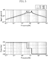
- a transfer function from the second actuator 33 to the displacement sensor 32 in the case of M1 > M2 is indicated by the solid lines in Fig. 5 .
- vibration transmitted from the floor 1 to the second object 21 in the case of M1 > M2 can be reduced to the further low-frequency side.
- a material of the second object 21 may differ from a material of the third object 22.
- tungsten or the like with large density can be employed.
- a displacement sensor (second displacement detector) 42 detects relative displacement between the control target 2 and the second object 21 (a relative position, or a position or displacement of the other with respect to one of the control target 2 and the second object 21), and outputs the relative displacement as a detection signal 41.
- the displacement sensor 42 is attached to the control target 2, but the displacement sensor 42 may be attached to the second object 21.
- the control target 2 is subjected to position feedback control by the feedback control system 9 based on the detection signal 41.
- An arithmetic unit (first arithmetic unit) 5 in the feedback control system 9 calculates, generates, and outputs a control signal (command value) 6 to the first actuator 4 based on the detection signal 41 and a target value 10.
- the 'arithmetic unit' may be called as a 'computing device'.
- the arithmetic unit 5 can be used as a PID compensator that performs PID compensation calculation.
- the PID compensator can set a crossover frequency thereof to 50 Hz, a break frequency of the integrator thereof to 8 Hz, and a break frequency of the differentiator thereof to 17 Hz.
- the displacement detector 42 may be a velocity sensor that detects a relative velocity between the control target 2 and the second object 21, or may be an acceleration sensor that detects relative acceleration between the control target 2 and the second object 21.
- the feedback control system 9 can be a velocity feedback control system, or an acceleration feedback control system.
- the effects of the present exemplary embodiment will be described below with reference to Fig. 6 and Fig. 7 .
- the dashed lines in Fig. 6 indicate a transfer function from the first base 8 to the control target 2 when the feedback control system 9 is turned off.
- the solid lines in Fig. 6 indicate a transfer function from the first base 8 to the control target 2 when the feedback control system 9 is turned on.
- a peak corresponding to the natural frequency of the first system appears.
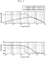
- the dashed lines in Fig. 7 indicate a transfer function of compliance (displacement/force, i.e., reciprocal of rigidity) of the control target 2 when the feedback control system 9 is turned off. Further, the solid lines in Fig. 7 indicate a transfer function of the compliance of the control target 2, when the feedback control system 9 is turned on. It can be seen that vibration with less than or equal to about 30 Hz generated on the control target 2 can be greatly reduced by turning on the feedback control system 9.
- the vibration control apparatus which can greatly reduces low-frequency vibration generated on the floor 1 and the control target 2 and transmitted to the control target 2 can be realized with use of the feedback control system 9.
- Such the vibration control apparatus is suitable for causing the control target 2 to follow the target value 10.
- the vibration control apparatus 50V can function as a vibration isolation apparatus by giving a predetermined constant as the target value 10. Further, the vibration control apparatus 50V can function as a vibrating apparatus that vibrates the control target 2 by giving a target value which changes with time as the target value 10.
- the vibration control apparatuses 50V and 50V1 are described which control vibration of the control target (the first object) 2 in the vertical direction.
- a vibration control apparatus 50H will be described which controls vibration of the control target (the first object) 2 in the horizontal direction.
- Fig. 8 illustrates a configuration of the vibration control apparatus 50H.
- the second object 21 is supported by the third object 22 via a second spring mechanism (plate spring) 23r.
- the third object 22 is supported by the second base 28 via a third spring mechanism (plate spring) 24r.
- the second base 28 is fixed onto the floor 1.
- the first spring mechanism 23r and the second spring mechanism 24r are configured to be symmetrical (axisymmetrical) with respect to a straight line connecting the center of gravity of the second object 21 and the center of gravity of the third object 22.
- the second object 21 and the third object 22 can be movably supported in the horizontal direction without using an expensive guide mechanism.
- a method for controlling the third object 22 and the control target 2 is similar to that in the first exemplary embodiment.
- a rotational mode (a tilt with respect to the horizontal direction) of the second object 21 or the third object 22 is excited, a feedback control system 39 can be oscillated.
- the second actuator 33 is arranged such that the straight line connecting the center of gravity of the second object 21 and the center of gravity of the third object 22 and an axis (a line of action of force) of the second actuator 33 become coaxial (overlapped) with each other. Accordingly, excitation of the rotational mode of the second object 21 or the third object 22 by the second actuator 33 can be suppressed.
- a displacement detector 32 is arranged on the straight line connecting the center of gravity of the second object 21 and the center of gravity of the third object 22. Accordingly, even if the rotational mode of the second object 21 or the third object 22 is excited, a measurement error due to the rotational mode in the output 31 can be reduced.
- the second object 21, the second spring mechanism 23r, the third object 22, the third spring mechanism 24r, the displacement detector 32, and the second actuator 33 are preferably arranged on the same axis.
- a displacement detector 42 is also arranged on the straight line connecting the center of gravity of the second object 21 and the center of gravity of the third object 22. Accordingly, an Abbe error in the detection signal 41 due to relative inclination between the control target 2 and the second object 21 can be reduced. In this manner, the displacement detector 42 is also preferably arranged on the above-described same axis.
- the displacement detector 42 in the detection systems 30V, 30V1, and 30H detect relative displacement between the control target 2 and the second object 21.
- the displacement detector 42 in a detection system 30V2 is configured to detect relative displacement between the control target 2 and the third object 22.
- the detection system 30V2 that detects relative displacement between the control target 2 and the third object 22 in the vertical direction will be described below by way of example. However, by referring to the second exemplary embodiment, it is apparent that the detection system that detects relative displacement between the control target 2 and the third object 22 in the horizontal direction can be constituted.
- the effects of the present exemplary embodiment will be described below with reference to Fig. 9 .
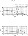
- the dashed lines in Fig. 9 indicate a transfer function from the second base 28 to the third object 22. Further, the solid lines in Fig. 9 indicate a transfer function from the second base 28 to the third object 22, in a case where the feedback control system 39 is constituted.
- the peaks corresponding to the natural frequency of the fourth system disappear, and it can be seen that vibration with low frequency of about 0.1 Hz or above, which is transmitted from the floor 1 to the third object 22, is greatly reduced.
- the dashed lines in Fig. 10 indicate a transfer function from the first base 8 to the control target 2, when the feedback control system 9 is turned off.
- the solid lines in Fig. 10 indicate a transfer function from the first base 8 to the control target 2, when the feedback control system 9 is turned on. It can be seen that low-frequency vibration ranging from about 0.1 Hz to about 20 Hz transmitted from the floor 1 to the control target 2 can be greatly reduced by turning on the feedback control system 9.
- the dashed lines in Fig. 11 indicate a transfer function of compliance of the control target 2, when the feedback control system 9 is turned off. Further, the solid lines in Fig. 11 indicate a transfer function of the compliance of the control target 2, when the feedback control system 9 is turned on. It can be seen that vibration with low frequency of about 30 Hz or below generated on the control target 2 can be greatly reduced by turning on the feedback control system 9.
- the low-frequency vibration transmitted to the control target 2 can be also greatly reduced by detecting the relative displacement between the control target 2 and the third object 22 with the displacement detector 42 and performing feedback control on the control target 2 based on the detection signal 41.
- the displacement detector 42 can be configured to output the relative displacement between at least one of the second object 21 and the third object 22 and the control target 2.
- the displacement detector 42 may be configured to selectively output the relative displacement between the control target 2 and the second object 21, or the relative displacement between the control target 2 and the third object 22.
- the displacement detector 42 may be configured to detect the relative displacement between the control target 2 and the second object 21 and the relative displacement between the control target 2 and the third object 22, and to output an average value of these detected values.
- a fourth exemplary embodiment includes at least six detection systems 30X (three or more detection systems relating to the horizontal direction, and three or more detection systems relating to the vertical direction) like the above-described detection systems 30V and 30H, and performs vibration control with six degrees of freedom on the control target 2.
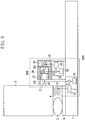
- Fig. 12A three detection systems relating to the vertical direction 30V_1, 30V_2 (not illustrated), and 30V_3, and three detection systems relating to the horizontal direction 30H_1, 30H_2, and 30H_3 (not illustrated) are mounted (arranged) on the floor 1.
- the detection signal 41 is obtained by the displacement detector 42 of each of the detection systems 30V_1, 30V_2, and 30V_3, and the detection systems 30H_1, 30H_2, and 30H_3.
- First actuators 104 are configured to include three actuators relating to a Z-axis direction, one actuator relating to an X-axis direction, and two actuators relating to a Y-axis direction in order to displace the control target 2 in six degrees of freedom.
- Fig. 12A among the six sets of the first actuators 104, only an actuator in the X-axis direction 104_X, an actuator in the Y-axis direction 104_Y1, and actuators in the Z-axis direction 104_Z1 and 104_Z2 are illustrated.
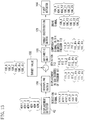
- Fig. 13 is a block line diagram illustrating vibration control of the control target 2 in six degrees of freedom.
- the detection signals 41 of the displacement detectors 42 are converted into displacement in six degrees of freedom (6 axes) 111 in X-Y-Z coordinate systems with the origin at the center of gravity of the control target 2 by a decoupling matrix 101.
- difference between the displacement information 111 and the target value 100 with respect to the control target 2 is calculated to determine deviation 112.
- the arithmetic unit 105 performs compensation calculation on the deviation 112, and outputs compensation signals 113 with six degrees of freedom for reducing the deviation.
- Six compensation signals 113 are respectively converted into six drive signals 106 of the first actuators 104 by a thrust distribution matrix 121.
- the obtained drive signals 106 are transmitted to the first actuators 104, and the control target 2 is displaced in the six degrees of freedom (6 axes directions). Through the above process, vibration of the control target 2 can be controlled in the six degrees of freedom.
- the detection system 30V and the detection system 30H described in either one of the first exemplary embodiment to the third exemplary embodiment can be used, respectively.
- three detection systems relating to the vertical direction 30V_1, 30V_2, and 30V_3, and three detection systems relating to the horizontal direction 30H_1, 30H_2, and 30H_3 are mounted (arranged) on the floor 1.
- the detection systems 30V_1, 30V_2, and 30V_3 and the detection systems 30H_1, 30H_2, and 30H_3 are mounted (arranged) on the control target 2.
- the second base 28 is fixed to the control target 2.
- the detection systems 30V_1, 30V_2, and 30V_3 and the detection systems 30H_1, 30H_2, and 30H_3 detect relative displacement between the control target 2 and the second object 21, or relative displacement between the control target 2 and the third object 22, and outputs the detection signals 41.
- Control of the control target 2 can be performed in a similar manner to the one described in the fourth exemplary embodiment.
- the detection system 30V and the detection system 30H according to the fifth exemplary embodiment 5 can be used, respectively.
- the manufacturing method can include a process for forming a latent image pattern on a photosensitive material coated on a substrate using the above-described drawing apparatus or the exposure apparatus and a process for developing the substrate on which the latent image pattern is formed by the forming process.
- the manufacturing method can include other well-known processes (e.g., oxidation, film formation, vapor deposition, doping, planarization, etching, resist stripping, dicing, bonding, and packaging).
- the manufacturing method for an article according to the present exemplary embodiment includes a process for forming a pattern on a substrate (e.g., wafer, glass plate or film-like substrate) using the above-described imprint apparatus. Further, the manufacturing method can include a process for etching the substrate on which the pattern is formed.
- a substrate e.g., wafer, glass plate or film-like substrate
- the manufacturing method can include other well-known processes (e.g., oxidation, film formation, vapor deposition, doping, planarization, resist stripping, dicing, bonding, and packaging).
- the manufacturing method can include another well-known process for processing the substrate on which the pattern is formed, in place of the above-described etching.
- the manufacturing method for articles according to the present exemplary embodiment includes a process for transferring a pattern onto a substrate using a lithography apparatus and a process for processing the substrate onto which the pattern is transferred by the transferring process.
- the manufacturing method for articles according to the present exemplary embodiment is suitable in terms of at least one of performance, quality, productivity, and production cost of the articles, as compared with the conventional method.
Landscapes
- Engineering & Computer Science (AREA)
- Physics & Mathematics (AREA)
- General Engineering & Computer Science (AREA)
- Health & Medical Sciences (AREA)
- General Physics & Mathematics (AREA)
- Acoustics & Sound (AREA)
- Aviation & Aerospace Engineering (AREA)
- Mechanical Engineering (AREA)
- Atmospheric Sciences (AREA)
- Toxicology (AREA)
- Environmental & Geological Engineering (AREA)
- Epidemiology (AREA)
- Public Health (AREA)
- Life Sciences & Earth Sciences (AREA)
- Automation & Control Theory (AREA)
- Exposure Of Semiconductors, Excluding Electron Or Ion Beam Exposure (AREA)
- Exposure And Positioning Against Photoresist Photosensitive Materials (AREA)
- Vibration Prevention Devices (AREA)
Applications Claiming Priority (1)
| Application Number | Priority Date | Filing Date | Title |
|---|---|---|---|
| JP2010244365A JP5641878B2 (ja) | 2010-10-29 | 2010-10-29 | 振動制御装置、リソグラフィー装置、および、物品の製造方法 |
Publications (3)
| Publication Number | Publication Date |
|---|---|
| EP2447776A2 EP2447776A2 (en) | 2012-05-02 |
| EP2447776A3 EP2447776A3 (en) | 2015-04-29 |
| EP2447776B1 true EP2447776B1 (en) | 2016-12-14 |
Family
ID=45033649
Family Applications (1)
| Application Number | Title | Priority Date | Filing Date |
|---|---|---|---|
| EP11008268.2A Not-in-force EP2447776B1 (en) | 2010-10-29 | 2011-10-13 | Vibration control apparatus, lithography apparatus, and method of manufacturing article |
Country Status (4)
| Country | Link |
|---|---|
| US (1) | US9052614B2 (ja) |
| EP (1) | EP2447776B1 (ja) |
| JP (1) | JP5641878B2 (ja) |
| KR (1) | KR101446383B1 (ja) |
Families Citing this family (12)
| Publication number | Priority date | Publication date | Assignee | Title |
|---|---|---|---|---|
| DE102008047562B4 (de) | 2008-09-16 | 2012-11-08 | Carl Zeiss Smt Gmbh | Vorrichtung zur Dämpfung von Schwingungen in Projektionsbelichtungsanlagen für die Halbleiterlithographie |
| DE102011007917A1 (de) * | 2011-04-21 | 2012-10-25 | Asml Netherlands B.V. | Anordnung zur Aktuierung eines Elementes in einer mikrolithographischen Projektionsbelichtungsanlage |
| KR101772504B1 (ko) * | 2012-11-27 | 2017-09-12 | 에이에스엠엘 네델란즈 비.브이. | 리소그래피 장치, 기판 지지 시스템, 디바이스 제조 방법 및 제어 프로그램 |
| DE102013201081A1 (de) * | 2013-01-24 | 2014-03-13 | Carl Zeiss Smt Gmbh | Vorrichtung zur Lagerung eines optischen Bauelements |
| JP6218459B2 (ja) * | 2013-07-02 | 2017-10-25 | キヤノン株式会社 | 除振装置、除振方法、リソグラフィ装置及びデバイスの製造方法 |
| US9664265B2 (en) * | 2013-09-12 | 2017-05-30 | Massachusetts Institute Of Technology | Methods and apparatus for selective rod actuation |
| JP6278676B2 (ja) * | 2013-11-29 | 2018-02-14 | キヤノン株式会社 | 振動低減装置、リソグラフィ装置、および物品の製造方法 |
| JP6302305B2 (ja) * | 2014-03-18 | 2018-03-28 | キヤノン株式会社 | 振動低減装置、リソグラフィ装置、および物品の製造方法 |
| JP6333081B2 (ja) * | 2014-06-23 | 2018-05-30 | キヤノン株式会社 | 振動制御装置、リソグラフィ装置、および物品の製造方法 |
| JP6697563B2 (ja) * | 2016-01-07 | 2020-05-20 | エーエスエムエル ネザーランズ ビー.ブイ. | リソグラフィ装置及びデバイス製造方法 |
| JP2018101671A (ja) * | 2016-12-19 | 2018-06-28 | キヤノン株式会社 | インプリント装置及び物品の製造方法 |
| WO2019035882A1 (en) * | 2017-08-15 | 2019-02-21 | Technical Manufacturing Corporation | ISOLATION SYSTEM FOR PRECISION VIBRATION WITH PREDICTIVE FLOOR ASSISTANCE |
Family Cites Families (26)
| Publication number | Priority date | Publication date | Assignee | Title |
|---|---|---|---|---|
| IL77057A (en) * | 1985-03-26 | 1990-03-19 | Wright Barry Corp | Active vibration isolation system |
| JPH0483708A (ja) | 1990-07-24 | 1992-03-17 | Asahi Glass Co Ltd | 硝酸の回収方法 |
| JP3581499B2 (ja) | 1996-09-27 | 2004-10-27 | キヤノン株式会社 | 除振装置及びその制御方法 |
| JPH11230246A (ja) | 1998-02-18 | 1999-08-27 | Tokkyo Kiki Kk | アクティブ除振装置 |
| JP3554186B2 (ja) * | 1998-04-08 | 2004-08-18 | キヤノン株式会社 | 露光装置、デバイス製造方法および反力受け方法 |
| JPH11315883A (ja) * | 1998-04-30 | 1999-11-16 | Canon Inc | 除振装置、露光装置およびデバイス製造方法 |
| JP2978162B1 (ja) * | 1998-08-25 | 1999-11-15 | 財団法人神奈川科学技術アカデミー | アクティブ除振装置 |
| TW468090B (en) * | 1998-12-17 | 2001-12-11 | Asm Lithography Bv | Servo control method, and its application in a lithographic projection apparatus |
| US6563128B2 (en) * | 2001-03-09 | 2003-05-13 | Cymer, Inc. | Base stabilization system |
| KR100555930B1 (ko) * | 2001-01-19 | 2006-03-03 | 에이에스엠엘 네델란즈 비.브이. | 리소그래피 장치, 디바이스 제조방법 및 그 디바이스 |
| JP2003058254A (ja) | 2001-08-13 | 2003-02-28 | Canon Inc | 位置・姿勢制御装置 |
| EP1321822A1 (en) * | 2001-12-21 | 2003-06-25 | ASML Netherlands B.V. | Lithographic apparatus and device manufacturing method |
| US20050035074A1 (en) * | 2003-05-19 | 2005-02-17 | Mcgarry Matthew | Wall mountable display racks, hangers, and associated display methods |
| US7084956B2 (en) * | 2003-06-13 | 2006-08-01 | Asml Netherlands B.V | Supporting device, lithographic apparatus, and device manufacturing method employing a supporting device, and a position control system arranged for use in a supporting device |
| US7248339B2 (en) * | 2003-07-04 | 2007-07-24 | Asml Netherlands B.V. | Lithographic apparatus and device manufacturing method |
| DE602004030259D1 (de) * | 2003-09-05 | 2011-01-05 | Koninkl Philips Electronics Nv | Stellgliedanordnung für aktive schwingungsisolierung mit einer trägheitsbezugsmasse |
| WO2005073592A1 (en) * | 2004-01-26 | 2005-08-11 | Koninklijke Philips Electronics N.V. | Actuator arrangement for active vibration isolation using a payload as an inertial reference mass |
| US7817243B2 (en) * | 2004-04-12 | 2010-10-19 | Asml Netherlands B.V. | Vibration isolation system |
| US7726452B2 (en) * | 2005-06-02 | 2010-06-01 | Technical Manufacturing Corporation | Systems and methods for active vibration damping |
| CN101305206A (zh) * | 2005-11-08 | 2008-11-12 | 皇家飞利浦电子股份有限公司 | 振动隔离系统及方法 |
| JP2009520202A (ja) * | 2005-12-20 | 2009-05-21 | コーニンクレッカ フィリップス エレクトロニクス エヌ ヴィ | 合成センサシステム及び方法 |
| JP4934356B2 (ja) | 2006-06-20 | 2012-05-16 | 株式会社日立製作所 | 映像処理エンジンおよびそれを含む映像処理システム |
| JP5036259B2 (ja) * | 2006-09-14 | 2012-09-26 | キヤノン株式会社 | 除振装置、露光装置及びデバイス製造方法 |
| WO2008146877A1 (ja) * | 2007-05-31 | 2008-12-04 | Nikon Corporation | 防振装置、防振装置の制御方法、及び露光装置 |
| US20090201484A1 (en) * | 2007-10-29 | 2009-08-13 | Nikon Corporation | Utilities supply member connection apparatus, stage apparatus, projection optical system support apparatus and exposure apparatus |
| NL2003772A (en) * | 2008-12-11 | 2010-06-14 | Asml Netherlands Bv | Lithographic apparatus and a method to compensate for the effect of disturbances on the projection system of a lithographic apparatus. |
-
2010
- 2010-10-29 JP JP2010244365A patent/JP5641878B2/ja not_active Expired - Fee Related
-
2011
- 2011-10-13 EP EP11008268.2A patent/EP2447776B1/en not_active Not-in-force
- 2011-10-24 US US13/280,243 patent/US9052614B2/en not_active Expired - Fee Related
- 2011-10-28 KR KR1020110110920A patent/KR101446383B1/ko active IP Right Grant
Non-Patent Citations (1)
| Title |
|---|
| None * |
Also Published As
| Publication number | Publication date |
|---|---|
| US9052614B2 (en) | 2015-06-09 |
| US20120105820A1 (en) | 2012-05-03 |
| EP2447776A3 (en) | 2015-04-29 |
| JP5641878B2 (ja) | 2014-12-17 |
| JP2012097786A (ja) | 2012-05-24 |
| EP2447776A2 (en) | 2012-05-02 |
| KR20120046054A (ko) | 2012-05-09 |
| KR101446383B1 (ko) | 2014-10-01 |
Similar Documents
| Publication | Publication Date | Title |
|---|---|---|
| EP2447776B1 (en) | Vibration control apparatus, lithography apparatus, and method of manufacturing article | |
| JP4209121B2 (ja) | デュアル分離されたシステムを有するリソグラフィーツールおよびそれを構成する方法 | |
| JP4834439B2 (ja) | ステージ装置及びその制御方法、露光装置及びデバイス製造方法 | |
| US7768626B2 (en) | Exposure apparatus | |
| JP2004100953A (ja) | 制振装置及び露光装置 | |
| US6392741B1 (en) | Projection exposure apparatus having active vibration isolator and method of controlling vibration by the active vibration isolator | |
| US9435642B2 (en) | Position measuring apparatus, pattern transfer apparatus, and method for manufacturing a device | |
| KR101977308B1 (ko) | 능동형 제진장치 이용한 이송장치의 외란 제어방법 | |
| JP5789153B2 (ja) | 露光装置及びデバイス製造方法 | |
| WO1999026120A1 (fr) | Eliminateur de vibrations, dispositif d'alignement et procede d'exposition par projection | |
| JPH11150062A (ja) | 除振装置及び露光装置並びに除振台の除振方法 | |
| JP6278676B2 (ja) | 振動低減装置、リソグラフィ装置、および物品の製造方法 | |
| JP2007240396A (ja) | 振動検出センサ、防振装置、及び露光装置 | |
| US9599185B2 (en) | Vibration control apparatus, lithography apparatus, and article manufacturing method | |
| TW200817844A (en) | Anti-vibration apparatus, exposure apparatus, and device manufacturing method | |
| US8619361B2 (en) | Direct derivative feedforward vibration compensation system | |
| JP3629772B2 (ja) | 除振装置、ステージ装置、露光装置及び走査型露光装置 | |
| KR100483982B1 (ko) | 진동절연장치및노광장치 | |
| JP2001242937A (ja) | ステージ装置 | |
| JP6016432B2 (ja) | 位置決め装置、露光装置、デバイス製造方法 | |
| JP2000012435A (ja) | 除振装置および露光装置 | |
| JP3807516B2 (ja) | 除振装置、除振方法及び露光装置 | |
| JP3636337B2 (ja) | 除振装置及び露光装置 | |
| JPH09330875A (ja) | 除振装置及び露光装置 | |
| JP2000228343A (ja) | アクティブ除振装置、露光装置およびデバイス製造方法 |
Legal Events
| Date | Code | Title | Description |
|---|---|---|---|
| PUAI | Public reference made under article 153(3) epc to a published international application that has entered the european phase |
Free format text: ORIGINAL CODE: 0009012 |
|
| AK | Designated contracting states |
Kind code of ref document: A2 Designated state(s): AL AT BE BG CH CY CZ DE DK EE ES FI FR GB GR HR HU IE IS IT LI LT LU LV MC MK MT NL NO PL PT RO RS SE SI SK SM TR |
|
| AX | Request for extension of the european patent |
Extension state: BA ME |
|
| PUAL | Search report despatched |
Free format text: ORIGINAL CODE: 0009013 |
|
| AK | Designated contracting states |
Kind code of ref document: A3 Designated state(s): AL AT BE BG CH CY CZ DE DK EE ES FI FR GB GR HR HU IE IS IT LI LT LU LV MC MK MT NL NO PL PT RO RS SE SI SK SM TR |
|
| AX | Request for extension of the european patent |
Extension state: BA ME |
|
| RIC1 | Information provided on ipc code assigned before grant |
Ipc: G03F 7/20 20060101AFI20150324BHEP |
|
| 17P | Request for examination filed |
Effective date: 20151029 |
|
| RBV | Designated contracting states (corrected) |
Designated state(s): AL AT BE BG CH CY CZ DE DK EE ES FI FR GB GR HR HU IE IS IT LI LT LU LV MC MK MT NL NO PL PT RO RS SE SI SK SM TR |
|
| GRAP | Despatch of communication of intention to grant a patent |
Free format text: ORIGINAL CODE: EPIDOSNIGR1 |
|
| INTG | Intention to grant announced |
Effective date: 20160426 |
|
| RIN1 | Information on inventor provided before grant (corrected) |
Inventor name: ASADA, KATSUMI Inventor name: NAWATA, RYO |
|
| GRAJ | Information related to disapproval of communication of intention to grant by the applicant or resumption of examination proceedings by the epo deleted |
Free format text: ORIGINAL CODE: EPIDOSDIGR1 |
|
| INTC | Intention to grant announced (deleted) | ||
| GRAR | Information related to intention to grant a patent recorded |
Free format text: ORIGINAL CODE: EPIDOSNIGR71 |
|
| GRAS | Grant fee paid |
Free format text: ORIGINAL CODE: EPIDOSNIGR3 |
|
| INTG | Intention to grant announced |
Effective date: 20160915 |
|
| GRAA | (expected) grant |
Free format text: ORIGINAL CODE: 0009210 |
|
| AK | Designated contracting states |
Kind code of ref document: B1 Designated state(s): AL AT BE BG CH CY CZ DE DK EE ES FI FR GB GR HR HU IE IS IT LI LT LU LV MC MK MT NL NO PL PT RO RS SE SI SK SM TR |
|
| REG | Reference to a national code |
Ref country code: GB Ref legal event code: FG4D |
|
| REG | Reference to a national code |
Ref country code: CH Ref legal event code: EP |
|
| REG | Reference to a national code |
Ref country code: IE Ref legal event code: FG4D |
|
| REG | Reference to a national code |
Ref country code: AT Ref legal event code: REF Ref document number: 854115 Country of ref document: AT Kind code of ref document: T Effective date: 20170115 |
|
| REG | Reference to a national code |
Ref country code: DE Ref legal event code: R096 Ref document number: 602011033304 Country of ref document: DE |
|
| PG25 | Lapsed in a contracting state [announced via postgrant information from national office to epo] |
Ref country code: LV Free format text: LAPSE BECAUSE OF FAILURE TO SUBMIT A TRANSLATION OF THE DESCRIPTION OR TO PAY THE FEE WITHIN THE PRESCRIBED TIME-LIMIT Effective date: 20161214 |
|
| REG | Reference to a national code |
Ref country code: LT Ref legal event code: MG4D |
|
| REG | Reference to a national code |
Ref country code: NL Ref legal event code: MP Effective date: 20161214 |
|
| PG25 | Lapsed in a contracting state [announced via postgrant information from national office to epo] |
Ref country code: GR Free format text: LAPSE BECAUSE OF FAILURE TO SUBMIT A TRANSLATION OF THE DESCRIPTION OR TO PAY THE FEE WITHIN THE PRESCRIBED TIME-LIMIT Effective date: 20170315 Ref country code: SE Free format text: LAPSE BECAUSE OF FAILURE TO SUBMIT A TRANSLATION OF THE DESCRIPTION OR TO PAY THE FEE WITHIN THE PRESCRIBED TIME-LIMIT Effective date: 20161214 Ref country code: LT Free format text: LAPSE BECAUSE OF FAILURE TO SUBMIT A TRANSLATION OF THE DESCRIPTION OR TO PAY THE FEE WITHIN THE PRESCRIBED TIME-LIMIT Effective date: 20161214 Ref country code: NO Free format text: LAPSE BECAUSE OF FAILURE TO SUBMIT A TRANSLATION OF THE DESCRIPTION OR TO PAY THE FEE WITHIN THE PRESCRIBED TIME-LIMIT Effective date: 20170314 |
|
| REG | Reference to a national code |
Ref country code: AT Ref legal event code: MK05 Ref document number: 854115 Country of ref document: AT Kind code of ref document: T Effective date: 20161214 |
|
| PG25 | Lapsed in a contracting state [announced via postgrant information from national office to epo] |
Ref country code: FI Free format text: LAPSE BECAUSE OF FAILURE TO SUBMIT A TRANSLATION OF THE DESCRIPTION OR TO PAY THE FEE WITHIN THE PRESCRIBED TIME-LIMIT Effective date: 20161214 Ref country code: HR Free format text: LAPSE BECAUSE OF FAILURE TO SUBMIT A TRANSLATION OF THE DESCRIPTION OR TO PAY THE FEE WITHIN THE PRESCRIBED TIME-LIMIT Effective date: 20161214 Ref country code: RS Free format text: LAPSE BECAUSE OF FAILURE TO SUBMIT A TRANSLATION OF THE DESCRIPTION OR TO PAY THE FEE WITHIN THE PRESCRIBED TIME-LIMIT Effective date: 20161214 |
|
| PG25 | Lapsed in a contracting state [announced via postgrant information from national office to epo] |
Ref country code: NL Free format text: LAPSE BECAUSE OF FAILURE TO SUBMIT A TRANSLATION OF THE DESCRIPTION OR TO PAY THE FEE WITHIN THE PRESCRIBED TIME-LIMIT Effective date: 20161214 |
|
| PG25 | Lapsed in a contracting state [announced via postgrant information from national office to epo] |
Ref country code: RO Free format text: LAPSE BECAUSE OF FAILURE TO SUBMIT A TRANSLATION OF THE DESCRIPTION OR TO PAY THE FEE WITHIN THE PRESCRIBED TIME-LIMIT Effective date: 20161214 Ref country code: CZ Free format text: LAPSE BECAUSE OF FAILURE TO SUBMIT A TRANSLATION OF THE DESCRIPTION OR TO PAY THE FEE WITHIN THE PRESCRIBED TIME-LIMIT Effective date: 20161214 Ref country code: SK Free format text: LAPSE BECAUSE OF FAILURE TO SUBMIT A TRANSLATION OF THE DESCRIPTION OR TO PAY THE FEE WITHIN THE PRESCRIBED TIME-LIMIT Effective date: 20161214 Ref country code: EE Free format text: LAPSE BECAUSE OF FAILURE TO SUBMIT A TRANSLATION OF THE DESCRIPTION OR TO PAY THE FEE WITHIN THE PRESCRIBED TIME-LIMIT Effective date: 20161214 Ref country code: IS Free format text: LAPSE BECAUSE OF FAILURE TO SUBMIT A TRANSLATION OF THE DESCRIPTION OR TO PAY THE FEE WITHIN THE PRESCRIBED TIME-LIMIT Effective date: 20170414 |
|
| PG25 | Lapsed in a contracting state [announced via postgrant information from national office to epo] |
Ref country code: IT Free format text: LAPSE BECAUSE OF FAILURE TO SUBMIT A TRANSLATION OF THE DESCRIPTION OR TO PAY THE FEE WITHIN THE PRESCRIBED TIME-LIMIT Effective date: 20161214 Ref country code: PL Free format text: LAPSE BECAUSE OF FAILURE TO SUBMIT A TRANSLATION OF THE DESCRIPTION OR TO PAY THE FEE WITHIN THE PRESCRIBED TIME-LIMIT Effective date: 20161214 Ref country code: ES Free format text: LAPSE BECAUSE OF FAILURE TO SUBMIT A TRANSLATION OF THE DESCRIPTION OR TO PAY THE FEE WITHIN THE PRESCRIBED TIME-LIMIT Effective date: 20161214 Ref country code: BE Free format text: LAPSE BECAUSE OF FAILURE TO SUBMIT A TRANSLATION OF THE DESCRIPTION OR TO PAY THE FEE WITHIN THE PRESCRIBED TIME-LIMIT Effective date: 20161214 Ref country code: AT Free format text: LAPSE BECAUSE OF FAILURE TO SUBMIT A TRANSLATION OF THE DESCRIPTION OR TO PAY THE FEE WITHIN THE PRESCRIBED TIME-LIMIT Effective date: 20161214 Ref country code: SM Free format text: LAPSE BECAUSE OF FAILURE TO SUBMIT A TRANSLATION OF THE DESCRIPTION OR TO PAY THE FEE WITHIN THE PRESCRIBED TIME-LIMIT Effective date: 20161214 Ref country code: PT Free format text: LAPSE BECAUSE OF FAILURE TO SUBMIT A TRANSLATION OF THE DESCRIPTION OR TO PAY THE FEE WITHIN THE PRESCRIBED TIME-LIMIT Effective date: 20170414 Ref country code: BG Free format text: LAPSE BECAUSE OF FAILURE TO SUBMIT A TRANSLATION OF THE DESCRIPTION OR TO PAY THE FEE WITHIN THE PRESCRIBED TIME-LIMIT Effective date: 20170314 |
|
| REG | Reference to a national code |
Ref country code: DE Ref legal event code: R097 Ref document number: 602011033304 Country of ref document: DE |
|
| PLBE | No opposition filed within time limit |
Free format text: ORIGINAL CODE: 0009261 |
|
| STAA | Information on the status of an ep patent application or granted ep patent |
Free format text: STATUS: NO OPPOSITION FILED WITHIN TIME LIMIT |
|
| 26N | No opposition filed |
Effective date: 20170915 |
|
| PG25 | Lapsed in a contracting state [announced via postgrant information from national office to epo] |
Ref country code: DK Free format text: LAPSE BECAUSE OF FAILURE TO SUBMIT A TRANSLATION OF THE DESCRIPTION OR TO PAY THE FEE WITHIN THE PRESCRIBED TIME-LIMIT Effective date: 20161214 |
|
| PG25 | Lapsed in a contracting state [announced via postgrant information from national office to epo] |
Ref country code: SI Free format text: LAPSE BECAUSE OF FAILURE TO SUBMIT A TRANSLATION OF THE DESCRIPTION OR TO PAY THE FEE WITHIN THE PRESCRIBED TIME-LIMIT Effective date: 20161214 |
|
| PG25 | Lapsed in a contracting state [announced via postgrant information from national office to epo] |
Ref country code: MC Free format text: LAPSE BECAUSE OF FAILURE TO SUBMIT A TRANSLATION OF THE DESCRIPTION OR TO PAY THE FEE WITHIN THE PRESCRIBED TIME-LIMIT Effective date: 20161214 |
|
| REG | Reference to a national code |
Ref country code: CH Ref legal event code: PL |
|
| GBPC | Gb: european patent ceased through non-payment of renewal fee |
Effective date: 20171013 |
|
| REG | Reference to a national code |
Ref country code: IE Ref legal event code: MM4A |
|
| REG | Reference to a national code |
Ref country code: FR Ref legal event code: ST Effective date: 20180629 |
|
| PG25 | Lapsed in a contracting state [announced via postgrant information from national office to epo] |
Ref country code: LU Free format text: LAPSE BECAUSE OF NON-PAYMENT OF DUE FEES Effective date: 20171013 Ref country code: GB Free format text: LAPSE BECAUSE OF NON-PAYMENT OF DUE FEES Effective date: 20171013 Ref country code: CH Free format text: LAPSE BECAUSE OF NON-PAYMENT OF DUE FEES Effective date: 20171031 Ref country code: LI Free format text: LAPSE BECAUSE OF NON-PAYMENT OF DUE FEES Effective date: 20171031 |
|
| PG25 | Lapsed in a contracting state [announced via postgrant information from national office to epo] |
Ref country code: FR Free format text: LAPSE BECAUSE OF NON-PAYMENT OF DUE FEES Effective date: 20171031 |
|
| PG25 | Lapsed in a contracting state [announced via postgrant information from national office to epo] |
Ref country code: MT Free format text: LAPSE BECAUSE OF NON-PAYMENT OF DUE FEES Effective date: 20171013 |
|
| PG25 | Lapsed in a contracting state [announced via postgrant information from national office to epo] |
Ref country code: IE Free format text: LAPSE BECAUSE OF NON-PAYMENT OF DUE FEES Effective date: 20171013 |
|
| PG25 | Lapsed in a contracting state [announced via postgrant information from national office to epo] |
Ref country code: HU Free format text: LAPSE BECAUSE OF FAILURE TO SUBMIT A TRANSLATION OF THE DESCRIPTION OR TO PAY THE FEE WITHIN THE PRESCRIBED TIME-LIMIT; INVALID AB INITIO Effective date: 20111013 |
|
| PG25 | Lapsed in a contracting state [announced via postgrant information from national office to epo] |
Ref country code: CY Free format text: LAPSE BECAUSE OF NON-PAYMENT OF DUE FEES Effective date: 20161214 |
|
| PG25 | Lapsed in a contracting state [announced via postgrant information from national office to epo] |
Ref country code: MK Free format text: LAPSE BECAUSE OF FAILURE TO SUBMIT A TRANSLATION OF THE DESCRIPTION OR TO PAY THE FEE WITHIN THE PRESCRIBED TIME-LIMIT Effective date: 20161214 |
|
| PG25 | Lapsed in a contracting state [announced via postgrant information from national office to epo] |
Ref country code: TR Free format text: LAPSE BECAUSE OF FAILURE TO SUBMIT A TRANSLATION OF THE DESCRIPTION OR TO PAY THE FEE WITHIN THE PRESCRIBED TIME-LIMIT Effective date: 20161214 |
|
| PG25 | Lapsed in a contracting state [announced via postgrant information from national office to epo] |
Ref country code: AL Free format text: LAPSE BECAUSE OF FAILURE TO SUBMIT A TRANSLATION OF THE DESCRIPTION OR TO PAY THE FEE WITHIN THE PRESCRIBED TIME-LIMIT Effective date: 20161214 |
|
| PGFP | Annual fee paid to national office [announced via postgrant information from national office to epo] |
Ref country code: DE Payment date: 20201228 Year of fee payment: 10 |
|
| REG | Reference to a national code |
Ref country code: DE Ref legal event code: R119 Ref document number: 602011033304 Country of ref document: DE |
|
| PG25 | Lapsed in a contracting state [announced via postgrant information from national office to epo] |
Ref country code: DE Free format text: LAPSE BECAUSE OF NON-PAYMENT OF DUE FEES Effective date: 20220503 |