EP2445659B1 - Verfahren und vorrichtung zum bearbeiten einer bramme - Google Patents
Verfahren und vorrichtung zum bearbeiten einer bramme Download PDFInfo
- Publication number
- EP2445659B1 EP2445659B1 EP09777913.6A EP09777913A EP2445659B1 EP 2445659 B1 EP2445659 B1 EP 2445659B1 EP 09777913 A EP09777913 A EP 09777913A EP 2445659 B1 EP2445659 B1 EP 2445659B1
- Authority
- EP
- European Patent Office
- Prior art keywords
- slab
- location
- lateral force
- exertion
- furnace
- Prior art date
- Legal status (The legal status is an assumption and is not a legal conclusion. Google has not performed a legal analysis and makes no representation as to the accuracy of the status listed.)
- Not-in-force
Links
Images

Classifications
-
- B—PERFORMING OPERATIONS; TRANSPORTING
- B21—MECHANICAL METAL-WORKING WITHOUT ESSENTIALLY REMOVING MATERIAL; PUNCHING METAL
- B21B—ROLLING OF METAL
- B21B39/00—Arrangements for moving, supporting, or positioning work, or controlling its movement, combined with or arranged in, or specially adapted for use in connection with, metal-rolling mills
- B21B39/14—Guiding, positioning or aligning work
-
- B—PERFORMING OPERATIONS; TRANSPORTING
- B21—MECHANICAL METAL-WORKING WITHOUT ESSENTIALLY REMOVING MATERIAL; PUNCHING METAL
- B21B—ROLLING OF METAL
- B21B1/00—Metal-rolling methods or mills for making semi-finished products of solid or profiled cross-section; Sequence of operations in milling trains; Layout of rolling-mill plant, e.g. grouping of stands; Succession of passes or of sectional pass alternations
- B21B1/22—Metal-rolling methods or mills for making semi-finished products of solid or profiled cross-section; Sequence of operations in milling trains; Layout of rolling-mill plant, e.g. grouping of stands; Succession of passes or of sectional pass alternations for rolling plates, strips, bands or sheets of indefinite length
- B21B1/24—Metal-rolling methods or mills for making semi-finished products of solid or profiled cross-section; Sequence of operations in milling trains; Layout of rolling-mill plant, e.g. grouping of stands; Succession of passes or of sectional pass alternations for rolling plates, strips, bands or sheets of indefinite length in a continuous or semi-continuous process
- B21B1/26—Metal-rolling methods or mills for making semi-finished products of solid or profiled cross-section; Sequence of operations in milling trains; Layout of rolling-mill plant, e.g. grouping of stands; Succession of passes or of sectional pass alternations for rolling plates, strips, bands or sheets of indefinite length in a continuous or semi-continuous process by hot-rolling, e.g. Steckel hot mill
-
- B—PERFORMING OPERATIONS; TRANSPORTING
- B21—MECHANICAL METAL-WORKING WITHOUT ESSENTIALLY REMOVING MATERIAL; PUNCHING METAL
- B21B—ROLLING OF METAL
- B21B1/00—Metal-rolling methods or mills for making semi-finished products of solid or profiled cross-section; Sequence of operations in milling trains; Layout of rolling-mill plant, e.g. grouping of stands; Succession of passes or of sectional pass alternations
- B21B1/46—Metal-rolling methods or mills for making semi-finished products of solid or profiled cross-section; Sequence of operations in milling trains; Layout of rolling-mill plant, e.g. grouping of stands; Succession of passes or of sectional pass alternations for rolling metal immediately subsequent to continuous casting
- B21B1/466—Metal-rolling methods or mills for making semi-finished products of solid or profiled cross-section; Sequence of operations in milling trains; Layout of rolling-mill plant, e.g. grouping of stands; Succession of passes or of sectional pass alternations for rolling metal immediately subsequent to continuous casting in a non-continuous process, i.e. the cast being cut before rolling
-
- B—PERFORMING OPERATIONS; TRANSPORTING
- B21—MECHANICAL METAL-WORKING WITHOUT ESSENTIALLY REMOVING MATERIAL; PUNCHING METAL
- B21B—ROLLING OF METAL
- B21B13/00—Metal-rolling stands, i.e. an assembly composed of a stand frame, rolls, and accessories
- B21B13/06—Metal-rolling stands, i.e. an assembly composed of a stand frame, rolls, and accessories with axes of rolls arranged vertically, e.g. edgers
-
- B—PERFORMING OPERATIONS; TRANSPORTING
- B21—MECHANICAL METAL-WORKING WITHOUT ESSENTIALLY REMOVING MATERIAL; PUNCHING METAL
- B21B—ROLLING OF METAL
- B21B1/00—Metal-rolling methods or mills for making semi-finished products of solid or profiled cross-section; Sequence of operations in milling trains; Layout of rolling-mill plant, e.g. grouping of stands; Succession of passes or of sectional pass alternations
- B21B1/02—Metal-rolling methods or mills for making semi-finished products of solid or profiled cross-section; Sequence of operations in milling trains; Layout of rolling-mill plant, e.g. grouping of stands; Succession of passes or of sectional pass alternations for rolling heavy work, e.g. ingots, slabs, blooms, or billets, in which the cross-sectional form is unimportant ; Rolling combined with forging or pressing
- B21B2001/028—Slabs
-
- B—PERFORMING OPERATIONS; TRANSPORTING
- B21—MECHANICAL METAL-WORKING WITHOUT ESSENTIALLY REMOVING MATERIAL; PUNCHING METAL
- B21B—ROLLING OF METAL
- B21B15/00—Arrangements for performing additional metal-working operations specially combined with or arranged in, or specially adapted for use in connection with, metal-rolling mills
- B21B15/0007—Cutting or shearing the product
- B21B2015/0014—Cutting or shearing the product transversely to the rolling direction
-
- B—PERFORMING OPERATIONS; TRANSPORTING
- B21—MECHANICAL METAL-WORKING WITHOUT ESSENTIALLY REMOVING MATERIAL; PUNCHING METAL
- B21B—ROLLING OF METAL
- B21B39/00—Arrangements for moving, supporting, or positioning work, or controlling its movement, combined with or arranged in, or specially adapted for use in connection with, metal-rolling mills
- B21B39/14—Guiding, positioning or aligning work
- B21B39/16—Guiding, positioning or aligning work immediately before entering or after leaving the pass
-
- B—PERFORMING OPERATIONS; TRANSPORTING
- B21—MECHANICAL METAL-WORKING WITHOUT ESSENTIALLY REMOVING MATERIAL; PUNCHING METAL
- B21B—ROLLING OF METAL
- B21B45/00—Devices for surface or other treatment of work, specially combined with or arranged in, or specially adapted for use in connection with, metal-rolling mills
- B21B45/004—Heating the product
-
- B—PERFORMING OPERATIONS; TRANSPORTING
- B21—MECHANICAL METAL-WORKING WITHOUT ESSENTIALLY REMOVING MATERIAL; PUNCHING METAL
- B21B—ROLLING OF METAL
- B21B45/00—Devices for surface or other treatment of work, specially combined with or arranged in, or specially adapted for use in connection with, metal-rolling mills
- B21B45/04—Devices for surface or other treatment of work, specially combined with or arranged in, or specially adapted for use in connection with, metal-rolling mills for de-scaling, e.g. by brushing
- B21B45/06—Devices for surface or other treatment of work, specially combined with or arranged in, or specially adapted for use in connection with, metal-rolling mills for de-scaling, e.g. by brushing of strip material
-
- B—PERFORMING OPERATIONS; TRANSPORTING
- B21—MECHANICAL METAL-WORKING WITHOUT ESSENTIALLY REMOVING MATERIAL; PUNCHING METAL
- B21B—ROLLING OF METAL
- B21B45/00—Devices for surface or other treatment of work, specially combined with or arranged in, or specially adapted for use in connection with, metal-rolling mills
- B21B45/04—Devices for surface or other treatment of work, specially combined with or arranged in, or specially adapted for use in connection with, metal-rolling mills for de-scaling, e.g. by brushing
- B21B45/08—Devices for surface or other treatment of work, specially combined with or arranged in, or specially adapted for use in connection with, metal-rolling mills for de-scaling, e.g. by brushing hydraulically
-
- Y—GENERAL TAGGING OF NEW TECHNOLOGICAL DEVELOPMENTS; GENERAL TAGGING OF CROSS-SECTIONAL TECHNOLOGIES SPANNING OVER SEVERAL SECTIONS OF THE IPC; TECHNICAL SUBJECTS COVERED BY FORMER USPC CROSS-REFERENCE ART COLLECTIONS [XRACs] AND DIGESTS
- Y10—TECHNICAL SUBJECTS COVERED BY FORMER USPC
- Y10T—TECHNICAL SUBJECTS COVERED BY FORMER US CLASSIFICATION
- Y10T29/00—Metal working
- Y10T29/45—Scale remover or preventor
- Y10T29/4517—Rolling deformation or deflection
Definitions
- the invention relates to a method for processing a slab in a device having at least one furnace, at least one downstream of the furnace in the conveying direction of the slab processing device and one of the at least one processing device in the conveying direction of the slab rolling train, wherein means are provided with which a force can be exerted on the sides of the slab to move the axis of the slab in accordance with a predetermined position transverse to the conveying direction of the slab, in particular in accordance with the axis of the rolling train. Furthermore, the invention relates to a device for processing a slab.
- the DE 43 10 547 C2 also discloses a solution for centering a slab, but also here several and long rulers are used, which in this case come before the finishing train for the above reason out of the question. A similar solution goes out of the JP 63101004 A out.
- the present invention has for its object to provide a method of the type mentioned above and a corresponding device, with which it is possible with simple means just before the rolling mill, especially in front of the finishing line to center the slab exactly and to lead and in particular to allow a secure upsetting over the entire slab length. Furthermore, a problem-free rolling at the top and at the end of the slab should be ensured.
- the rolling process should thus be optimized by accurately introducing the slab into the rolling train. In particular, it is provided to realize the centering and guiding the slab just before the finishing mill so that no appreciable extension of the distance between the furnace and the finishing train is created.
- the solution of this object by the invention is procedurally characterized in that first means for exerting a lateral force on the slab at a first location act on the slab and that second means for exerting a lateral force on the slab at a second location on the slab act, wherein the second location in the conveying direction of the slab is spaced from the first location, wherein the first location is behind the furnace and wherein the second location in front of, inside or behind the at least one processing device.
- a more specific embodiment of the invention provides that the first location is behind the furnace and before the first of the at least one processing device, and that the second location lies within or behind the first of the at least one processing device.
- Rolling in the rolling train may be finish rolling the slab into a belt.
- a reliable mode of operation can be ensured if the position of the head of the slab in the region of at least one of the means is detected and the exertion of a lateral force on the slab by the delivery of a Contact element of the agent is started only when the head of the slab has passed the means.
- the slab can be subjected to a compression in the direction transverse to the conveying direction.
- the exertion of a lateral force on the slab by the means before the location of the compression and spaced therefrom takes place.
- the exertion of a lateral force on the slab by the means preferably takes place in front of the rolling train.
- the means for exerting a lateral force on the slab are preferably operated so that the tip of the slab runs centrally into the place of compression and / or into the rolling train.
- At least two means for exerting a lateral force on the slab may be disposed behind the furnace, the first location between the furnace and the first processing device and the second location between the at least two processing devices or within the second processing device. In this case, it has proven useful if the slab is subjected to a shearing process in the first processing device. In the second processing apparatus, the slab is preferably subjected to a descaling process.
- a further development provides that the position and / or the shape of the slab are determined transversely to the conveying direction of the slab along its movement in the conveying direction before the first location.
- the exertion of a lateral force on the slab from the means can be carried out in a controlled or regulated manner such that the axis of the slab in the conveying direction behind the second location assumes a desired position.
- the adjustment of the means for exerting a lateral force on the slab may be determined using a mathematical model depending on the geometry of the device and / or the shape of the slab and / or the eccentricity of the slab and / or the width of the slab.
- the device for processing a slab which has at least one furnace, at least one downstream of the furnace in the conveying direction of the slab processing device and one of the at least one processing device in the conveying direction of the slab downstream rolling train, in particular a finishing train, as well as means with which on the sides of the Slab can be exerted a force to move the axis of the slab in accordance with a predetermined position transverse to the conveying direction of the slab, in particular in accordance with the axis of the rolling mill, according to the invention provides that first means for exerting a lateral force on the Slabs are arranged at a first location and that second means for exerting a lateral force on the slab at a second location, the second location in the conveying direction of the slab being spaced from the first location, wherein the first location is behind the oven and wherein the second place before, pauses is located halfway or behind the at least one processing device.
- the first location is behind the oven and before the at least one processing device and that the second location is within or behind the first of the at least one processing device.
- the area within the furnace is preferably free of means for exerting a lateral force on the slab.
- a stuffer can be arranged for upsetting the slab in the direction transverse to the conveying direction.
- Side guide rulers for centering and guiding the slab may be arranged between the upshot and the first rolling stand of the rolling train. Furthermore, adjusting elements of the side guide rulers can be arranged below and / or above the side guide rulers.
- the means for exerting a lateral force on the slab may be spaced from the upset. They can also be arranged in front of the rolling train.
- a refinement provides that at least two means for exerting a lateral force are arranged on the slab behind the furnace, the first location being between the furnace and the first processing device and the second location lying between the at least two processing devices or within the second processing device.
- the first processing device is preferably a pair of scissors.
- the second processing device is preferably a descaling device.
- the means for exerting a lateral force on the slab may comprise at least one roller which is arranged on a pivot arm, wherein the swivel arm is mounted fixed at a bearing point and can be pivoted by an actuator which acts outside of the bearing point on the swivel arm.
- the means for exerting a lateral force on the slab can also comprise at least one roller, which is arranged on a linear actuator whose direction of movement is oriented transversely to the conveying direction of the slab.
- a training provides that the actuator or the linear actuator is designed as a hydraulic piston-cylinder system.
- the first means for exerting a lateral force on the slab can also be designed as guide rulers.
- the proposed device is preferably part of a thin slab casting rolling mill. It may also be part of a hot strip mill having a roughing and finishing line; In this case, the device is preferably arranged in front of the finishing train.
- the invention is based on the fact that a centering and guiding the slab just before the finishing train with roller side guides done so that a total of short distance between the furnace and finishing mill.
- the roller side guides are housed between the individual units (processing devices) at a suitable distance.
- an upshot and a mechanical or hydraulic side guide are preferably arranged in front of the first rolling stand of the finishing train.
- the proposed solution is preferably used in the so-called CSP technology. This is understood to mean the manufacture of a steel strip in a thin-slab caster rolling mill, which enables efficient production of hot strip.
- the proposed measures can increase the output and reduce the number of Kokillenver einen.
- a direct width control in front of the finishing train is made possible.
- the tape is improved.
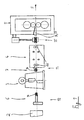
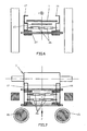
- FIGS. 1 and 2 is a device to see with a slab 1 can be processed in their promotion in the conveying direction F. Specifically, an end portion of a furnace 2 is shown and the first rolling stand of a rolling line 5, between which the slab 1 is conveyed. Between the furnace 2 and the rolling train 5, a first processing device 3 in the form of a pair of scissors and a second processing device 4 in the form of a descaling device are arranged.
- roller side guides which are equipped with contact elements in the form of rollers 14 which are against the sides of the 8th and 9 of the slab 1 can be pressed to center the slab so that the axis 10 of the slab 1 coincides with the axis 11 of the rolling train 5.
- the first means 6 for exerting a lateral force on the slab 1 at a first location 12 act on the slab 1 and that the second means 7 for exerting a lateral force on the slab 1 at a second location 13 on the slab 1 act.
- the second location 13 in the conveying direction F of the slab 1 is spaced from the first location 12;
- the first location 12 is behind the furnace 2 and before the first processing device 3, wherein the second location 13 is located inside or behind the first processing device 3 - in the embodiment between the two processing devices 3 and 4.
- the two means 6 and 7 thus provide for a centering of the slab, so that it enters centrally into a stuffer 15, which is arranged immediately in front of the first rolling stand of the finishing train 5. Between edger 15 and the first rolling stand of the finishing train 5 side guide rulers 16 and 17 are further arranged, which further center the slab 1.
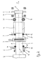
- the means 6, 7 may have a pivot arm 18 which is mounted in a fixed bearing point 19 and carries at its end remote from the bearing point 19 end of the roller 14.
- An actuator 20 engages the pivot arm 18 and provides for the corresponding adjustment of the roller 14 against the side 8, 9 of the slab.
- the means 6, 7 may also comprise a linear actuator 21 which delivers the roller 14 directly linearly against the belt edge.
- the threading into the stuffer 15 is by driving rollers 22 (s. Fig. 1 ), which are integrated into the descaling device 4, at least until the stuffer 15 or the first stand of the finishing train 5 have taken supported.
- the second roller side guide pair 7, ie the second means for exerting a lateral force on the slab, can be arranged before the descaling device as shown, integrated within the Entzundingsvoriques or disposed behind the descaling device.
- a drive of the rollers 14 of the means 6 and 7 are provided.
- the second roller side guide 7 can be set in a straight guide in the width direction (see embodiment at the second location 13 in FIG Fig. 2 ) or via a swivel arm (as at the first location 12 in FIG Fig. 2 ).
- roller side guide roller instead of a larger roller side guide roller is in an alternative embodiment (not shown), the arrangement of two smaller close together arranged double roles in a leadership unit possible, but always so that is still given the short design. With the two roller side guides 6 and 7, which are spaced apart, the effect of a long continuous side guide is achieved. The roller side guides 6, 7 thereby form a control unit.
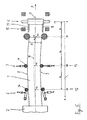
- the optimal positioning of the roller side guides 6, 7 is somewhat more complicated. It is then made a detection of the slab shape and the position over the slab length. For this purpose, laser distance measurements or other position detection signals are provided, for example, in front of the last oven part (behind the ferry), as shown in FIG Fig. 4 is illustrated for the detection and determination of the slab shape and position over the length. Also entered here is the eccentricity ⁇ y of the slab from the axis of the system.
- the width, position or generally the shape of the slab determines the length.
- the form and eccentricity ⁇ y i determined here are later used for optimum positioning of the roller side guides 6, 7 and / or the rollers of the stuffer 15.
- slab width and slab position detection behind the oven is also possible from the sides by means of the sensors 24 or from above or below.
- the positions of the rollers 14 and the rollers of the upshot 15 (X1, Y1, X2, Y2, X3, Y3 relative to the slab center) can be approached become.
- the positions are adapted when passing through the slab tip from the furnace 2 to the first stand of the finishing train 5 to the respective slab shape and partially moved so that the goal is achieved to guide the slab tip in the center of the edger 15.
- the rollers of the stuffer 15 can be asymmetrical, ie off-center, to support the roller side guides 6, 7.
- the goal is to center or center the roller side guides 6, 7 and the upshot 15 over the length of the slab, so that the slab 1 and in particular the slab end is as straight as possible is and thus enters the mill 5.
- the rollers of the upset 15 are fed in symmetrically (short stroke control) in order to avoid or reduce the excess width at the end of the slab. The same goes for the slab head.
- the width or position detection can take place via the displacement transmitters of the roller side guides and / or compression rollers. Furthermore, the detected width signal as well as the calculated spread or width change in the finishing train in the width model are used to determine the amount of compression and thus to control the stuffer.
- Niedefialte- or clamping rollers are provided, which are located exactly between the two compression rollers and press from the top and bottom in the middle of the slab 1 on the slab surface to prevent bulging.
- the compression rollers are lubricated. This increases the material crossflow, reduces the compression and buckling forces and also has a positive effect on the slab and compression roll roughness and thus on the life of the edging rolls.
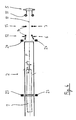
- a special mechanical side guide between the stuffer 15 and the first stand of the rolling train 5 is additionally provided (s. Fig. 1 and 2 ). Details on this go from the FIGS. 6 and 7 out.
- the aim is to arrange the stuffer 15 close to the first stand of the rolling train 5 and to position the mechanical side guide as close as possible to the first nip of the first stand.
- an adjustment of the mechanical side guides, d. h of the side guide rulers 16 and 17 can be performed without additional space and without weakening the stand posts of the rolling stand (with recesses therein), an adjustment below (or optionally also above) the side guide ruler 16, 17 is provided as advantageous 6 and 7 results.
- the adjustment of the side guide rulers 16, 17 is carried out together with the upsetting 15 employment. In this case, upseters and guide rulers would be firmly connected.
- the adjustment of the side guide rulers 16, 17 on a guide 27 is performed by two adjusting elements 26 (cylinders) per side.
- the adjusting elements 26 are provided at the top with a heat protection element 25 (cooled transfer table, insulation board).
- the position of the mechanical lateral guide during operation corresponds to the width position of the upshot 15 plus a defined amount (in millimeters).
- the described method and the apparatus shown are not limited to a CSP plant, but are also used in similar production plants behind a furnace part.
- the proposal according to the invention can also be used for example in conventional hot strip mills.
- the Vorbandform is detected behind a roughing stand during transport direction finishing mill and there met with suitable employment of roles before the finishing road the above objectives.
- the first centering effect in front of the shears can alternatively be carried out by guide rulers as an alternative to the use of the roller side guide unit 6.
Landscapes
- Engineering & Computer Science (AREA)
- Mechanical Engineering (AREA)
- Metal Rolling (AREA)
- Heat Treatments In General, Especially Conveying And Cooling (AREA)
Applications Claiming Priority (2)
| Application Number | Priority Date | Filing Date | Title |
|---|---|---|---|
| DE102009029887 | 2009-06-23 | ||
| PCT/EP2009/005942 WO2010149192A1 (de) | 2009-06-23 | 2009-08-17 | Verfahren und vorrichtung zum bearbeiten einer bramme |
Publications (2)
| Publication Number | Publication Date |
|---|---|
| EP2445659A1 EP2445659A1 (de) | 2012-05-02 |
| EP2445659B1 true EP2445659B1 (de) | 2014-04-09 |
Family
ID=41277477
Family Applications (1)
| Application Number | Title | Priority Date | Filing Date |
|---|---|---|---|
| EP09777913.6A Not-in-force EP2445659B1 (de) | 2009-06-23 | 2009-08-17 | Verfahren und vorrichtung zum bearbeiten einer bramme |
Country Status (13)
| Country | Link |
|---|---|
| US (1) | US20120096914A1 (enExample) |
| EP (1) | EP2445659B1 (enExample) |
| JP (1) | JP2012512746A (enExample) |
| KR (1) | KR101320930B1 (enExample) |
| CN (1) | CN102245322B (enExample) |
| AU (1) | AU2009348758B2 (enExample) |
| BR (1) | BRPI0925061B1 (enExample) |
| CA (1) | CA2765269C (enExample) |
| MX (1) | MX2011013099A (enExample) |
| RU (1) | RU2479367C2 (enExample) |
| UA (1) | UA100935C2 (enExample) |
| WO (1) | WO2010149192A1 (enExample) |
| ZA (1) | ZA201103236B (enExample) |
Cited By (1)
| Publication number | Priority date | Publication date | Assignee | Title |
|---|---|---|---|---|
| DE102021203170A1 (de) | 2021-03-30 | 2022-10-06 | Sms Group Gmbh | Verfahren zum Führen und Zentrieren eines metallenen Walzguts in einer Walzstraße |
Families Citing this family (13)
| Publication number | Priority date | Publication date | Assignee | Title |
|---|---|---|---|---|
| EP2666558A1 (de) * | 2012-05-21 | 2013-11-27 | Siemens Aktiengesellschaft | Seitenführung für eine Walzstraße |
| EP2689863A1 (de) | 2012-07-27 | 2014-01-29 | Siemens Aktiengesellschaft | Verfahren zur gezielten Beeinflussung der Geometrie eines Walzguts |
| DE102012224505A1 (de) * | 2012-12-28 | 2014-07-03 | Sms Siemag Aktiengesellschaft | Vorrichtung und Verfahren zum seitlichen Führen eines Walz- oder Gießerzeugnisses auf einer Transportstraße |
| CN103567233A (zh) * | 2013-10-26 | 2014-02-12 | 芜湖新兴铸管有限责任公司 | 一种开坯机机后移钢推板 |
| SE538558C2 (en) * | 2014-12-18 | 2016-09-20 | Morgårdshammar Ab | A roller guide and a method for guiding stock |
| JP6753420B2 (ja) | 2016-02-02 | 2020-09-09 | 日本製鉄株式会社 | 鋳片反り検出装置、及び鋳片の反り検出方法 |
| US10799925B2 (en) * | 2016-05-13 | 2020-10-13 | Nippon Steel Corporation | Edging method and edging device |
| CN108016918A (zh) * | 2017-09-04 | 2018-05-11 | 海宁市睿创机械科技有限公司 | 半成品料的定中装置 |
| CN107838202B (zh) * | 2017-12-27 | 2019-07-26 | 安徽楚江特钢有限公司 | 一种带钢精轧机进口导位装置 |
| EP3714999B1 (de) * | 2019-03-28 | 2022-09-28 | Primetals Technologies Germany GmbH | Ermittlung einer anstellung eines walzgerüsts |
| DE102020206297A1 (de) * | 2019-09-19 | 2021-03-25 | Sms Group Gmbh | Zwischengerüstführung an einem Vertikalwalzgerüst einer Walzstraße sowie Verfahren zur Führung des Walzgutes unter Verwendung der Zwischengerüstführung |
| CN113695391B (zh) * | 2021-09-15 | 2023-01-17 | 鞍钢股份有限公司 | 一种热轧集装箱用钢宽度超极限的生产方法 |
| DE102024102520A1 (de) * | 2024-01-30 | 2025-07-31 | Sms Group Gmbh | Zentriervorrichtung, Heizstrecke, Walzwerk und Verwendung eines Zentriermittels |
Family Cites Families (17)
| Publication number | Priority date | Publication date | Assignee | Title |
|---|---|---|---|---|
| JPS5522464A (en) * | 1978-08-07 | 1980-02-18 | Hitachi Ltd | Continuous rolling method of slab |
| JPS63101004A (ja) * | 1986-10-15 | 1988-05-06 | Ishikawajima Harima Heavy Ind Co Ltd | 圧延設備 |
| US5218848A (en) * | 1990-02-13 | 1993-06-15 | Hitachi, Ltd. | Method and apparatus for correcting a widthwise bend in an end portion of a hot-rolled sheet-shaped product |
| JP2757553B2 (ja) * | 1990-10-19 | 1998-05-25 | 石川島播磨重工業株式会社 | スタンド内サイドガイド装置および制御方法 |
| US5634360A (en) * | 1992-09-21 | 1997-06-03 | Ishikawajima-Harima Heavy Industries Co., Ltd. | Guiding apparatus for roughing mill |
| EP0641614B1 (en) * | 1993-01-28 | 2001-11-14 | Nippon Steel Corporation | Continuous hot rolling method and rolled material joining apparatus |
| DE19540978A1 (de) * | 1995-11-03 | 1997-05-07 | Schloemann Siemag Ag | Produktionsanlage zum kontinuierlichen- oder diskontinuierlichen Auswalzen von Warmband |
| US5927118A (en) * | 1996-05-28 | 1999-07-27 | Nkk Corporation | Method for making hot-rolled steel sheet and apparatus therefor |
| DE19713604A1 (de) * | 1997-04-02 | 1998-10-08 | Schloemann Siemag Ag | Einer Fertigstraße für stranggegossenes Bandmaterial vorgeordnetes positionsgeregeltes Stauchgerüst |
| NL1007730C2 (nl) * | 1997-12-08 | 1999-06-09 | Hoogovens Staal Bv | Inrichting en werkwijze voor het vervaardigen van een stalen band. |
| JP2000246309A (ja) * | 1999-03-01 | 2000-09-12 | Kobe Steel Ltd | 高強度鋼板の圧延設備列 |
| JP3914674B2 (ja) * | 2000-01-18 | 2007-05-16 | 新日本製鐵株式会社 | 熱間粗圧延機における圧延材の搬送方法 |
| IT1314793B1 (it) * | 2000-02-15 | 2003-01-16 | Danieli Off Mecc | Procedimento di controllo assialita' per bramme uscenti da colatacontinua e relativo dispositivo. |
| JP3596484B2 (ja) * | 2000-05-10 | 2004-12-02 | 住友金属工業株式会社 | 熱間圧延設備および熱間圧延方法 |
| DE10109055A1 (de) * | 2001-02-24 | 2002-09-05 | Sms Demag Ag | Stranggießanlage mit nachgeordneten Öfen, Vorwalzgerüsten sowie einer Fertigstraße |
| AT410549B (de) * | 2001-09-13 | 2003-05-26 | Voest Alpine Schienen Gmbh & C | Vorrichtung zum vergüten von walzgut mit grosser länge |
| JP4778832B2 (ja) * | 2006-05-17 | 2011-09-21 | 三菱日立製鉄機械株式会社 | 先,後行金属板の幅揃え方法及び装置と連続圧延設備 |
-
2009
- 2009-08-17 CN CN200980151587.3A patent/CN102245322B/zh not_active Expired - Fee Related
- 2009-08-17 RU RU2011129323/02A patent/RU2479367C2/ru active
- 2009-08-17 JP JP2011541118A patent/JP2012512746A/ja active Pending
- 2009-08-17 MX MX2011013099A patent/MX2011013099A/es active IP Right Grant
- 2009-08-17 BR BRPI0925061-1A patent/BRPI0925061B1/pt not_active IP Right Cessation
- 2009-08-17 WO PCT/EP2009/005942 patent/WO2010149192A1/de not_active Ceased
- 2009-08-17 KR KR1020117011892A patent/KR101320930B1/ko not_active Expired - Fee Related
- 2009-08-17 UA UAA201109118A patent/UA100935C2/ru unknown
- 2009-08-17 AU AU2009348758A patent/AU2009348758B2/en not_active Ceased
- 2009-08-17 EP EP09777913.6A patent/EP2445659B1/de not_active Not-in-force
- 2009-08-17 US US13/379,404 patent/US20120096914A1/en not_active Abandoned
- 2009-08-17 CA CA2765269A patent/CA2765269C/en not_active Expired - Fee Related
-
2011
- 2011-05-05 ZA ZA2011/03236A patent/ZA201103236B/en unknown
Cited By (2)
| Publication number | Priority date | Publication date | Assignee | Title |
|---|---|---|---|---|
| DE102021203170A1 (de) | 2021-03-30 | 2022-10-06 | Sms Group Gmbh | Verfahren zum Führen und Zentrieren eines metallenen Walzguts in einer Walzstraße |
| WO2022207151A1 (de) | 2021-03-30 | 2022-10-06 | Sms Group Gmbh | Verfahren und vorrcihtung zum führen und zentrieren eines metallenen walzguts in einer walzstrasse |
Also Published As
| Publication number | Publication date |
|---|---|
| WO2010149192A1 (de) | 2010-12-29 |
| WO2010149192A9 (de) | 2011-04-21 |
| AU2009348758B2 (en) | 2013-08-29 |
| US20120096914A1 (en) | 2012-04-26 |
| JP2012512746A (ja) | 2012-06-07 |
| AU2009348758A1 (en) | 2012-01-19 |
| RU2479367C2 (ru) | 2013-04-20 |
| KR20110079750A (ko) | 2011-07-07 |
| UA100935C2 (ru) | 2013-02-11 |
| CN102245322B (zh) | 2014-10-22 |
| BRPI0925061A2 (pt) | 2015-07-28 |
| EP2445659A1 (de) | 2012-05-02 |
| CN102245322A (zh) | 2011-11-16 |
| CA2765269C (en) | 2014-01-14 |
| KR101320930B1 (ko) | 2013-10-23 |
| MX2011013099A (es) | 2012-01-27 |
| BRPI0925061B1 (pt) | 2020-03-03 |
| ZA201103236B (en) | 2012-03-28 |
| CA2765269A1 (en) | 2010-12-29 |
| RU2011129323A (ru) | 2013-01-20 |
Similar Documents
| Publication | Publication Date | Title |
|---|---|---|
| EP2445659B1 (de) | Verfahren und vorrichtung zum bearbeiten einer bramme | |
| EP2938445B1 (de) | Vorrichtung und verfahren zum seitlichen führen eines walz- oder giesserzeugnisses auf einer transportstrasse | |
| EP3246102B1 (de) | Verfahren und vorrichtung zum abkühlen einer platte in einer kühlstrecke | |
| AT513299B1 (de) | Verfahren und Vorrichtung für eine Gieß-Walz-Verbundanlage | |
| AT509831B1 (de) | Verfahren und vorrichtung zur minimierung des bandzugs eines walzgutes | |
| EP3177412B1 (de) | Einstellen eines gezielten temperaturprofiles an bandkopf und bandfuss vor dem querteilen eines metallbands | |
| EP2217394B1 (de) | Verfahren und vorrichtung zum herstellen eines bandes aus metall | |
| DE60113657T2 (de) | Walzen von bandmaterial | |
| AT410767B (de) | Verfahren und vorrichtung zur kontinuierlichen herstellung eines gewalzten metallbandes aus einermetallschmelze | |
| DE112007000641B4 (de) | Kontinuierliche Kaltwalzanlage | |
| EP2741870B1 (de) | Walzanlage und verfahren zum walzen | |
| EP3544751B1 (de) | Bandlageregelung mit kraftbegrenzter anstellung von seitenführungen an das metallband und korrektur der walzenanstellung | |
| EP1132161A1 (de) | Verfahren zum Stranggiessen von Brammen, und insbesondere von Dünnbrammen | |
| DE2723720A1 (de) | Vorrichtung zum aufrechterhalten einer waehrend eines richtvorganges auf ein metallband ausgeuebten, bestimmten zugspannung | |
| EP1184120A2 (de) | Sägeblattabstützung an einer Vorrichtung zum Vermessen und Korriegieren des Spannungsprofils von Sägeblättern | |
| EP3826781B1 (de) | Verfahren und vorrichtung zur ermittlung der seitlichen bandkontur oder der position der bandkanten eines laufenden metallbandes | |
| EP4313437B1 (de) | Verfahren und vorrcihtung zum führen und zentrieren eines metallenen walzguts in einer walzstrasse | |
| EP4100177B1 (de) | Verfahren zur kalibrierung von vertikalrollen eines vertikalwalzgerüsts sowie walzstrasse mit einer kalibrieranordnung zur durchführung des verfahrens | |
| AT526531B1 (de) | Entbartung von Walzgut mittels eines Schwingarms | |
| EP3873685B1 (de) | Walzlinie | |
| EP1020239A2 (de) | Verfahren und Anlage zum Walzen von Metallband | |
| DE102010063093B4 (de) | Vorrichtung und Verfahren zum horizontalen Gießen von Metallbändern | |
| DE102021209261A1 (de) | Verfahren zur Steuerung einer Walzgutführung in einer Walzstraße sowie Zwischengerüstführung |
Legal Events
| Date | Code | Title | Description |
|---|---|---|---|
| PUAI | Public reference made under article 153(3) epc to a published international application that has entered the european phase |
Free format text: ORIGINAL CODE: 0009012 |
|
| 17P | Request for examination filed |
Effective date: 20110428 |
|
| AK | Designated contracting states |
Kind code of ref document: A1 Designated state(s): AT BE BG CH CY CZ DE DK EE ES FI FR GB GR HR HU IE IS IT LI LT LU LV MC MK MT NL NO PL PT RO SE SI SK SM TR |
|
| DAX | Request for extension of the european patent (deleted) | ||
| GRAP | Despatch of communication of intention to grant a patent |
Free format text: ORIGINAL CODE: EPIDOSNIGR1 |
|
| INTG | Intention to grant announced |
Effective date: 20131126 |
|
| GRAS | Grant fee paid |
Free format text: ORIGINAL CODE: EPIDOSNIGR3 |
|
| GRAA | (expected) grant |
Free format text: ORIGINAL CODE: 0009210 |
|
| AK | Designated contracting states |
Kind code of ref document: B1 Designated state(s): AT BE BG CH CY CZ DE DK EE ES FI FR GB GR HR HU IE IS IT LI LT LU LV MC MK MT NL NO PL PT RO SE SI SK SM TR |
|
| REG | Reference to a national code |
Ref country code: GB Ref legal event code: FG4D Free format text: NOT ENGLISH |
|
| REG | Reference to a national code |
Ref country code: AT Ref legal event code: REF Ref document number: 661047 Country of ref document: AT Kind code of ref document: T Effective date: 20140415 Ref country code: CH Ref legal event code: EP |
|
| REG | Reference to a national code |
Ref country code: IE Ref legal event code: FG4D Free format text: LANGUAGE OF EP DOCUMENT: GERMAN |
|
| REG | Reference to a national code |
Ref country code: DE Ref legal event code: R096 Ref document number: 502009009157 Country of ref document: DE Effective date: 20140522 |
|
| REG | Reference to a national code |
Ref country code: NL Ref legal event code: VDEP Effective date: 20140409 |
|
| REG | Reference to a national code |
Ref country code: LT Ref legal event code: MG4D |
|
| PG25 | Lapsed in a contracting state [announced via postgrant information from national office to epo] |
Ref country code: BG Free format text: LAPSE BECAUSE OF FAILURE TO SUBMIT A TRANSLATION OF THE DESCRIPTION OR TO PAY THE FEE WITHIN THE PRESCRIBED TIME-LIMIT Effective date: 20140709 Ref country code: FI Free format text: LAPSE BECAUSE OF FAILURE TO SUBMIT A TRANSLATION OF THE DESCRIPTION OR TO PAY THE FEE WITHIN THE PRESCRIBED TIME-LIMIT Effective date: 20140409 Ref country code: IS Free format text: LAPSE BECAUSE OF FAILURE TO SUBMIT A TRANSLATION OF THE DESCRIPTION OR TO PAY THE FEE WITHIN THE PRESCRIBED TIME-LIMIT Effective date: 20140809 Ref country code: LT Free format text: LAPSE BECAUSE OF FAILURE TO SUBMIT A TRANSLATION OF THE DESCRIPTION OR TO PAY THE FEE WITHIN THE PRESCRIBED TIME-LIMIT Effective date: 20140409 Ref country code: GR Free format text: LAPSE BECAUSE OF FAILURE TO SUBMIT A TRANSLATION OF THE DESCRIPTION OR TO PAY THE FEE WITHIN THE PRESCRIBED TIME-LIMIT Effective date: 20140710 Ref country code: NO Free format text: LAPSE BECAUSE OF FAILURE TO SUBMIT A TRANSLATION OF THE DESCRIPTION OR TO PAY THE FEE WITHIN THE PRESCRIBED TIME-LIMIT Effective date: 20140709 Ref country code: NL Free format text: LAPSE BECAUSE OF FAILURE TO SUBMIT A TRANSLATION OF THE DESCRIPTION OR TO PAY THE FEE WITHIN THE PRESCRIBED TIME-LIMIT Effective date: 20140409 |
|
| PG25 | Lapsed in a contracting state [announced via postgrant information from national office to epo] |
Ref country code: PL Free format text: LAPSE BECAUSE OF FAILURE TO SUBMIT A TRANSLATION OF THE DESCRIPTION OR TO PAY THE FEE WITHIN THE PRESCRIBED TIME-LIMIT Effective date: 20140409 Ref country code: ES Free format text: LAPSE BECAUSE OF FAILURE TO SUBMIT A TRANSLATION OF THE DESCRIPTION OR TO PAY THE FEE WITHIN THE PRESCRIBED TIME-LIMIT Effective date: 20140409 Ref country code: HR Free format text: LAPSE BECAUSE OF FAILURE TO SUBMIT A TRANSLATION OF THE DESCRIPTION OR TO PAY THE FEE WITHIN THE PRESCRIBED TIME-LIMIT Effective date: 20140409 Ref country code: LV Free format text: LAPSE BECAUSE OF FAILURE TO SUBMIT A TRANSLATION OF THE DESCRIPTION OR TO PAY THE FEE WITHIN THE PRESCRIBED TIME-LIMIT Effective date: 20140409 Ref country code: SE Free format text: LAPSE BECAUSE OF FAILURE TO SUBMIT A TRANSLATION OF THE DESCRIPTION OR TO PAY THE FEE WITHIN THE PRESCRIBED TIME-LIMIT Effective date: 20140409 |
|
| PG25 | Lapsed in a contracting state [announced via postgrant information from national office to epo] |
Ref country code: PT Free format text: LAPSE BECAUSE OF FAILURE TO SUBMIT A TRANSLATION OF THE DESCRIPTION OR TO PAY THE FEE WITHIN THE PRESCRIBED TIME-LIMIT Effective date: 20140811 |
|
| REG | Reference to a national code |
Ref country code: DE Ref legal event code: R097 Ref document number: 502009009157 Country of ref document: DE |
|
| PG25 | Lapsed in a contracting state [announced via postgrant information from national office to epo] |
Ref country code: CZ Free format text: LAPSE BECAUSE OF FAILURE TO SUBMIT A TRANSLATION OF THE DESCRIPTION OR TO PAY THE FEE WITHIN THE PRESCRIBED TIME-LIMIT Effective date: 20140409 Ref country code: RO Free format text: LAPSE BECAUSE OF FAILURE TO SUBMIT A TRANSLATION OF THE DESCRIPTION OR TO PAY THE FEE WITHIN THE PRESCRIBED TIME-LIMIT Effective date: 20140409 Ref country code: DK Free format text: LAPSE BECAUSE OF FAILURE TO SUBMIT A TRANSLATION OF THE DESCRIPTION OR TO PAY THE FEE WITHIN THE PRESCRIBED TIME-LIMIT Effective date: 20140409 Ref country code: SK Free format text: LAPSE BECAUSE OF FAILURE TO SUBMIT A TRANSLATION OF THE DESCRIPTION OR TO PAY THE FEE WITHIN THE PRESCRIBED TIME-LIMIT Effective date: 20140409 Ref country code: EE Free format text: LAPSE BECAUSE OF FAILURE TO SUBMIT A TRANSLATION OF THE DESCRIPTION OR TO PAY THE FEE WITHIN THE PRESCRIBED TIME-LIMIT Effective date: 20140409 |
|
| PLBE | No opposition filed within time limit |
Free format text: ORIGINAL CODE: 0009261 |
|
| STAA | Information on the status of an ep patent application or granted ep patent |
Free format text: STATUS: NO OPPOSITION FILED WITHIN TIME LIMIT |
|
| 26N | No opposition filed |
Effective date: 20150112 |
|
| PG25 | Lapsed in a contracting state [announced via postgrant information from national office to epo] |
Ref country code: MC Free format text: LAPSE BECAUSE OF FAILURE TO SUBMIT A TRANSLATION OF THE DESCRIPTION OR TO PAY THE FEE WITHIN THE PRESCRIBED TIME-LIMIT Effective date: 20140409 Ref country code: LU Free format text: LAPSE BECAUSE OF FAILURE TO SUBMIT A TRANSLATION OF THE DESCRIPTION OR TO PAY THE FEE WITHIN THE PRESCRIBED TIME-LIMIT Effective date: 20140817 |
|
| REG | Reference to a national code |
Ref country code: CH Ref legal event code: PL |
|
| REG | Reference to a national code |
Ref country code: DE Ref legal event code: R097 Ref document number: 502009009157 Country of ref document: DE Effective date: 20150112 |
|
| GBPC | Gb: european patent ceased through non-payment of renewal fee |
Effective date: 20140817 |
|
| PG25 | Lapsed in a contracting state [announced via postgrant information from national office to epo] |
Ref country code: BE Free format text: LAPSE BECAUSE OF NON-PAYMENT OF DUE FEES Effective date: 20140831 Ref country code: LI Free format text: LAPSE BECAUSE OF NON-PAYMENT OF DUE FEES Effective date: 20140831 Ref country code: CH Free format text: LAPSE BECAUSE OF NON-PAYMENT OF DUE FEES Effective date: 20140831 |
|
| REG | Reference to a national code |
Ref country code: IE Ref legal event code: MM4A |
|
| REG | Reference to a national code |
Ref country code: FR Ref legal event code: ST Effective date: 20150430 |
|
| PG25 | Lapsed in a contracting state [announced via postgrant information from national office to epo] |
Ref country code: SI Free format text: LAPSE BECAUSE OF FAILURE TO SUBMIT A TRANSLATION OF THE DESCRIPTION OR TO PAY THE FEE WITHIN THE PRESCRIBED TIME-LIMIT Effective date: 20140409 Ref country code: GB Free format text: LAPSE BECAUSE OF NON-PAYMENT OF DUE FEES Effective date: 20140817 |
|
| REG | Reference to a national code |
Ref country code: DE Ref legal event code: R082 Ref document number: 502009009157 Country of ref document: DE Representative=s name: HEMMERICH & KOLLEGEN, DE Ref country code: DE Ref legal event code: R081 Ref document number: 502009009157 Country of ref document: DE Owner name: SMS GROUP GMBH, DE Free format text: FORMER OWNER: SMS SIEMAG AG, 40237 DUESSELDORF, DE |
|
| PG25 | Lapsed in a contracting state [announced via postgrant information from national office to epo] |
Ref country code: FR Free format text: LAPSE BECAUSE OF NON-PAYMENT OF DUE FEES Effective date: 20140901 Ref country code: IE Free format text: LAPSE BECAUSE OF NON-PAYMENT OF DUE FEES Effective date: 20140817 |
|
| PG25 | Lapsed in a contracting state [announced via postgrant information from national office to epo] |
Ref country code: SM Free format text: LAPSE BECAUSE OF FAILURE TO SUBMIT A TRANSLATION OF THE DESCRIPTION OR TO PAY THE FEE WITHIN THE PRESCRIBED TIME-LIMIT Effective date: 20140409 |
|
| PG25 | Lapsed in a contracting state [announced via postgrant information from national office to epo] |
Ref country code: MT Free format text: LAPSE BECAUSE OF FAILURE TO SUBMIT A TRANSLATION OF THE DESCRIPTION OR TO PAY THE FEE WITHIN THE PRESCRIBED TIME-LIMIT Effective date: 20140409 Ref country code: CY Free format text: LAPSE BECAUSE OF FAILURE TO SUBMIT A TRANSLATION OF THE DESCRIPTION OR TO PAY THE FEE WITHIN THE PRESCRIBED TIME-LIMIT Effective date: 20140409 |
|
| PG25 | Lapsed in a contracting state [announced via postgrant information from national office to epo] |
Ref country code: TR Free format text: LAPSE BECAUSE OF FAILURE TO SUBMIT A TRANSLATION OF THE DESCRIPTION OR TO PAY THE FEE WITHIN THE PRESCRIBED TIME-LIMIT Effective date: 20140409 Ref country code: HU Free format text: LAPSE BECAUSE OF FAILURE TO SUBMIT A TRANSLATION OF THE DESCRIPTION OR TO PAY THE FEE WITHIN THE PRESCRIBED TIME-LIMIT; INVALID AB INITIO Effective date: 20090817 |
|
| PG25 | Lapsed in a contracting state [announced via postgrant information from national office to epo] |
Ref country code: MK Free format text: LAPSE BECAUSE OF FAILURE TO SUBMIT A TRANSLATION OF THE DESCRIPTION OR TO PAY THE FEE WITHIN THE PRESCRIBED TIME-LIMIT Effective date: 20140409 |
|
| PGFP | Annual fee paid to national office [announced via postgrant information from national office to epo] |
Ref country code: DE Payment date: 20200819 Year of fee payment: 12 |
|
| PGFP | Annual fee paid to national office [announced via postgrant information from national office to epo] |
Ref country code: AT Payment date: 20200820 Year of fee payment: 12 Ref country code: IT Payment date: 20200826 Year of fee payment: 12 |
|
| REG | Reference to a national code |
Ref country code: DE Ref legal event code: R119 Ref document number: 502009009157 Country of ref document: DE |
|
| REG | Reference to a national code |
Ref country code: AT Ref legal event code: MM01 Ref document number: 661047 Country of ref document: AT Kind code of ref document: T Effective date: 20210817 |
|
| PG25 | Lapsed in a contracting state [announced via postgrant information from national office to epo] |
Ref country code: AT Free format text: LAPSE BECAUSE OF NON-PAYMENT OF DUE FEES Effective date: 20210817 |
|
| PG25 | Lapsed in a contracting state [announced via postgrant information from national office to epo] |
Ref country code: IT Free format text: LAPSE BECAUSE OF NON-PAYMENT OF DUE FEES Effective date: 20210817 Ref country code: DE Free format text: LAPSE BECAUSE OF NON-PAYMENT OF DUE FEES Effective date: 20220301 |