EP2428333A2 - Porte-outils - Google Patents
Porte-outils Download PDFInfo
- Publication number
- EP2428333A2 EP2428333A2 EP11174904A EP11174904A EP2428333A2 EP 2428333 A2 EP2428333 A2 EP 2428333A2 EP 11174904 A EP11174904 A EP 11174904A EP 11174904 A EP11174904 A EP 11174904A EP 2428333 A2 EP2428333 A2 EP 2428333A2
- Authority
- EP
- European Patent Office
- Prior art keywords
- tool holder
- tool
- holder according
- plug
- hand
- Prior art date
- Legal status (The legal status is an assumption and is not a legal conclusion. Google has not performed a legal analysis and makes no representation as to the accuracy of the status listed.)
- Granted
Links
- 238000003780 insertion Methods 0.000 claims abstract description 45
- 230000037431 insertion Effects 0.000 claims abstract description 45
- 239000006260 foam Substances 0.000 claims abstract description 14
- 239000000463 material Substances 0.000 claims abstract description 14
- 239000004033 plastic Substances 0.000 claims abstract description 5
- 229920003023 plastic Polymers 0.000 claims abstract description 5
- 229910052751 metal Inorganic materials 0.000 claims abstract description 4
- 239000002184 metal Substances 0.000 claims abstract description 4
- 239000007769 metal material Substances 0.000 claims abstract description 3
- 239000010410 layer Substances 0.000 claims description 54
- 239000012790 adhesive layer Substances 0.000 claims description 3
- 238000000034 method Methods 0.000 description 6
- 230000008569 process Effects 0.000 description 6
- 239000004793 Polystyrene Substances 0.000 description 4
- 239000006261 foam material Substances 0.000 description 4
- 229920002223 polystyrene Polymers 0.000 description 4
- 238000010276 construction Methods 0.000 description 3
- 239000004698 Polyethylene Substances 0.000 description 2
- 229920005830 Polyurethane Foam Polymers 0.000 description 2
- 210000004027 cell Anatomy 0.000 description 2
- 238000004140 cleaning Methods 0.000 description 2
- 230000000694 effects Effects 0.000 description 2
- 235000019589 hardness Nutrition 0.000 description 2
- 238000007689 inspection Methods 0.000 description 2
- 238000002372 labelling Methods 0.000 description 2
- 238000002360 preparation method Methods 0.000 description 2
- 238000004080 punching Methods 0.000 description 2
- 230000009467 reduction Effects 0.000 description 2
- 238000003860 storage Methods 0.000 description 2
- 239000003981 vehicle Substances 0.000 description 2
- 241000755266 Kathetostoma giganteum Species 0.000 description 1
- 230000009471 action Effects 0.000 description 1
- 229910052782 aluminium Inorganic materials 0.000 description 1
- XAGFODPZIPBFFR-UHFFFAOYSA-N aluminium Chemical compound [Al] XAGFODPZIPBFFR-UHFFFAOYSA-N 0.000 description 1
- 210000002421 cell wall Anatomy 0.000 description 1
- 230000001413 cellular effect Effects 0.000 description 1
- 210000003850 cellular structure Anatomy 0.000 description 1
- 238000010073 coating (rubber) Methods 0.000 description 1
- 238000005336 cracking Methods 0.000 description 1
- 230000001419 dependent effect Effects 0.000 description 1
- 238000013461 design Methods 0.000 description 1
- 238000006073 displacement reaction Methods 0.000 description 1
- 229920001971 elastomer Polymers 0.000 description 1
- 239000003925 fat Substances 0.000 description 1
- 230000005484 gravity Effects 0.000 description 1
- 238000009434 installation Methods 0.000 description 1
- 230000014759 maintenance of location Effects 0.000 description 1
- 238000004519 manufacturing process Methods 0.000 description 1
- 238000011089 mechanical engineering Methods 0.000 description 1
- 239000003921 oil Substances 0.000 description 1
- 230000002093 peripheral effect Effects 0.000 description 1
- 239000002984 plastic foam Substances 0.000 description 1
- -1 polyethylene Polymers 0.000 description 1
- 229920000573 polyethylene Polymers 0.000 description 1
- 229920001296 polysiloxane Polymers 0.000 description 1
- 239000011496 polyurethane foam Substances 0.000 description 1
- 239000011148 porous material Substances 0.000 description 1
- 238000012805 post-processing Methods 0.000 description 1
- 230000008439 repair process Effects 0.000 description 1
- 230000035939 shock Effects 0.000 description 1
- 239000002689 soil Substances 0.000 description 1
- 238000013517 stratification Methods 0.000 description 1
- 230000007704 transition Effects 0.000 description 1
- 238000009966 trimming Methods 0.000 description 1
Images


Classifications
-
- B—PERFORMING OPERATIONS; TRANSPORTING
- B25—HAND TOOLS; PORTABLE POWER-DRIVEN TOOLS; MANIPULATORS
- B25H—WORKSHOP EQUIPMENT, e.g. FOR MARKING-OUT WORK; STORAGE MEANS FOR WORKSHOPS
- B25H1/00—Work benches; Portable stands or supports for positioning portable tools or work to be operated on thereby
- B25H1/12—Work benches; Portable stands or supports for positioning portable tools or work to be operated on thereby with storage compartments
-
- B—PERFORMING OPERATIONS; TRANSPORTING
- B25—HAND TOOLS; PORTABLE POWER-DRIVEN TOOLS; MANIPULATORS
- B25H—WORKSHOP EQUIPMENT, e.g. FOR MARKING-OUT WORK; STORAGE MEANS FOR WORKSHOPS
- B25H3/00—Storage means or arrangements for workshops facilitating access to, or handling of, work tools or instruments
- B25H3/02—Boxes
-
- B—PERFORMING OPERATIONS; TRANSPORTING
- B25—HAND TOOLS; PORTABLE POWER-DRIVEN TOOLS; MANIPULATORS
- B25H—WORKSHOP EQUIPMENT, e.g. FOR MARKING-OUT WORK; STORAGE MEANS FOR WORKSHOPS
- B25H3/00—Storage means or arrangements for workshops facilitating access to, or handling of, work tools or instruments
- B25H3/06—Trays
Definitions
- the present invention relates to a tool holder for receiving hand tools according to the features in the preamble of claim 1.
- tool holders From the state of the art are known for professional use in motor vehicle repair shops, assembly halls or other mechanical engineering applications, but also in the private hobby area, tool holders. These tool holders are used to store an extensive range of tools, for example, consisting of a socket wrench assortment, screwdrivers, ring spanners, open-end wrenches, files, pliers and many other hand tools.
- the tool holders are known as a tool box, plug-in holder and the like. These are arranged or placed in or on tool boxes, workshop trolleys, workbenches.
- Object of the present invention is therefore, starting from the aforementioned prior art, to provide a tool holder, the offers improved accessibility and thus ergonomic work on the tool assortment and at the same time remains the same in terms of its outer dimensions compared to the tool holder known from the prior art. At the same time, it is an object of the present invention to accommodate a larger range of tools.
- the tool holder according to the invention for a tool assortment wherein the tool assortment preferably consists of a socket wrench assortment, screwdrivers, ring spanners and / or open-end wrenches, is characterized in that elongate hand tools are arranged with their longitudinal axis vertically oriented in the tool holder, wherein the tool holder is formed of foam.
- the position-fixed arrangement ensures a clearly structured arrangement of the individual hand tools. It is thus possible to directly access the particular hand tool required. Furthermore, the position-fixed arrangement prevents rattling of the tool during the movement of the workshop car. Likewise, a qualitatively high-quality appearance is ensured by the exactly aligned vertical arrangement of the elongated hand tools, which reflects the quality of the tools, especially for high-priced tools and tool accessories.
- the insert module has an adhesive layer on its underside.
- the adhesive layer can be, for example, a rubber coating or even another surface with a high coefficient of adhesion. This avoids that the insert module is moved unintentionally in a drawer itself by the opening and closing operation or the roles of a workshop carts on the one hand. Furthermore, when off insert module, for example a work surface, on the worktop of the workshop car or on any other surface, slipping or unintentional slight displacement can be avoided.
- the tool holder on handle means so that the tool holder is easily removed.
- This may, for example, handle handles that are pivotally mounted on the tool holder or retractable on the tool holder.
- handle handles In the case of a countersunk tool holder in a countertop or in a drawer itself, can take place on the handle means easy gripping the tool holder and thus repositioning the tool holder.
- the tool holder can be worn on the handle means in the manner of a toolbox with to a respective place of work. This ensures that it is avoided falling out of tools on the vertical arrangement of the tools themselves and the holding on the handle means.
- the tool holder is formed in particular of foam.
- various plastics can be used, which are formed with a cellular structure and low density.
- closed-cell foams in which the walls between the individual cells are completely closed or open-cell foams in which the cell walls are not closed can be used here.
- mixed-cell foams which contain both types of the aforementioned cells.
- Integral foams are also conceivable which have a closed thick outer skin and a cellular core on the other hand.
- the foams can have a wide variety of densities and / or at least partially different hardnesses.
- the foam materials used are in particular PU foam materials and / or PE foam materials used. These are polyethylene foams or polyurethane foams.
- densities between 5 and 80 kg / m 3 in particular between 10 and 70 kg / m 3 , preferably between 15 and 40 kg / m 3 and more preferably between 20 and 30 kg / m 3 are used.
- a density between 20 and 40 kg / m 3 in particular between 25 and 35 kg / m 3 and particularly preferably between 28 and 32 kg / m 3 is preferably used for the upper layer.
- the density of the lower intermediate layers and lower layers is selected between 10 and 50 kg / m 3 , in particular between 15 and 25 kg / m 3 and particularly preferably between 18 and 23 kg / m 3 . This in turn ensures that an increased clamping effect is achieved via the increased density at the upper layer and, in relation to this, at the lower layers an increased center of gravity lies on the pure guidance of the inserted hand tool.
- the tool holder can also be made of a polystyrene material or Styrodurmaterial. Due to the elastic configuration, it is possible to positionally fix the tools and to position them in a form-fitting manner and, if appropriate, additionally to fix them in a frictionally engaged manner. Falling out of the tools or a wobble of the tools in a tool holder according to the invention is therefore not possible.
- receiving openings are formed for receiving each hand tool itself in the tool holder, wherein the receiving openings are preferably configured individually for each hand tool in cross section.
- the cross-sectional area of the receiving openings essentially corresponds to the cross-sectional area of the hand tool and / or hand tool to be inserted into the receiving opening.
- the cross-sectional area of the receiving opening can be configured slightly smaller than the cross-sectional area of the corresponding hand tool, so that it can a frictional, non-slip Position fixation is coming.
- the receiving opening may be configured in its cross-sectional area also greater than the cross-sectional area of the corresponding hand tool, so that an easy removal or easy insertion is possible.
- the receiving openings between 1 and 40%, preferably between 5 and 30%, in particular by about 10% smaller than the outer dimensions of each contemplatsteckenden hand tool, in particular the tool shank.
- the receiving opening has at least one relief slot on the edge side.
- the cross-sectional area of the receiving opening is not damaged by cracking or the like.
- the relief slot thus surface tensions, which occur on the inner surface of the receiving opening, reduced or relieved.
- the receiving openings can therefore also be star-shaped or cross-shaped.
- a cleaning lip is arranged in the receiving opening itself.
- the cleaning lip or the receiving opening itself or the inside of the receiving opening it is thus possible to clean the tool during a plug-in or Aussteckvorgang.
- the tool holder is formed in multiple layers, wherein the layering of the layers is orthogonal to the vertical arrangement of the tools.
- the layering of the layers is orthogonal to the vertical arrangement of the tools.
- the receiving openings of the upper layer are furthermore preferably provided with a smaller receiving diameter in relation to the openings of the lower layers.
- a guiding and at the same time clamping action which counteracts a wobbling of a received tool, is ensured.
- the lower layers take over significantly a guiding effect, so that here an easy insertion and removal and yet a secure, fixed-position holding the hand tool is ensured in the receiving opening.
- the inner diameter of the receiving opening of the upper layer is preferably designed as an interference fit.
- a reduction of the diameter of the receiving opening with respect to the outer contour of the hand tool to be inserted between 1 and 40%, in particular between 5 and 30%, preferably between 10 and 20% is used.
- a transition fit is preferably carried out, in which case a reduction of the diameter of the receiving opening with respect to the outer dimension of the Schwarzsteckenden hand tool between 1 and 30%, in particular between 2 and 20% and particularly preferably at about 10% is present ,
- the tool holder a layer of a polystyrene material and another layer of a plastic foam.
- the individual layers For example, they can be glued together.
- the positive engagement between the layers themselves may be formed by, for example, a block principle or else with a respective through-bolt.
- the receiving openings in the tool holder for receiving the respective hand tool depending on its insertion depth are formed in layers.
- a receiving opening thus preferably penetrates one or more layers completely. It is thus possible, in the uppermost position, to form a receiving opening for each hand tool to be inserted completely permeating the position. In this case, it is possible to fall back on a cost-effective trimming or punching process.
- a socket wrench attachment only a small insertion depth of up to a maximum of 2 to 3 cm, compared to a screwdriver or a combination wrench, which has a depth of up to 10 cm or more, successively each layer of Viewed from the top position to be adapted to the respective insertion depth of the hand tool by punching out receiving openings in the respective position.
- a screwdriver comes through its tool shank and the coupled thereto handle in the region of the handle with the topmost layer to a shock, so that further plugging is no longer possible.
- a socket wrench itself, on the other hand, is designed as a cylindrical body and would correspondingly fall into a deeply formed receiving hole.
- the insertion depth can be set individually for each tool by the respective stratification.
- the adapted Embodiment is inventively achieved in that the respective receiving opening is not formed in the lower layers.
- the bottoms of the resulting receiving openings or insertion holes or insertion slots can in turn be formed with an additional bottom insert. Damage to the polystyrene or foam in the soil is thus largely avoided.
- the bottom insert itself may in turn be made of metal or a plastic, but at least of a harder in relation to the insert module material.
- the tool holder is arranged at the upper end of a plug-in, wherein the plug-in is coupled to the insert module.
- the plug-in plate is preferably and in its simplest form a perforated plate which prevents fraying of the insert, in particular the uppermost layer of the insert over the duration of a sometimes years or decades of use.
- the plug-in ensures that on the one hand, the surface of the uppermost layer is not damaged, on the other hand, a specific back putting the respective hand tool is possible.
- the plug-in to assign by labeling, engraving or by other labeling an insertion a respective tool.
- the plug-in plate is formed from a hard material in relation to the tool holder, preferably made of a plastic, in particular of a metallic material or very particularly preferably of a light metal, for example an aluminum material.
- a hard material in relation to the tool holder, preferably made of a plastic, in particular of a metallic material or very particularly preferably of a light metal, for example an aluminum material.
- the plug-in is coupled to the uppermost layer of the insert module, for example by non-positive and / or material connection.
- the insert is glued to the top layer.
- the plug-in plate itself has fixing mandrels, which in turn can be brought into positive engagement with the uppermost layer.
- the insertion plate has insertion openings, the insertion openings being adapted in their cross-sectional configuration to the respective tool cross-section to be inserted.
- the insertion of a respective tool must preferably for the special case of a larger tool head relative to the tool shaft, for example in the case of a fork wrench, have a corresponding insertion, so that the clevis is feasible through the insertion.
- the shank of the fork wrench in turn is fixed in position and oriented vertically in the tool holder.
- locking means are provided in the insertion plate in at least one insertion opening for fixing the position of the hand tool inserted therein.
- clamps or clamping lips or spring bars are to be understood, which fix this position when inserting the tool in addition positively and frictionally.
- the insertion opening has a cross-sectional configuration which has a larger opening cross-section, compared to the receiving opening of the insert below. This ensures that the insertion plate in each case carries out a purposeful insertion of the hand tool into the correct receiving opening accidental insertion into the surface or piercing into the surface of the insert is avoided. At the same time, however, a positive and frictional recording of the hand tool is ensured by the deposit below.
- a side edge is formed on the plug-in plate, wherein the side edge is formed projecting relative to the tool holder, in particular the foam base body of the tool holder.
- the tool holder can be coupled in different recesses. The relevant part of the tool holder is placed countersunk in the recess, whereas on the protruding side edge of the insert a form fit is given, so that a falling through the recess is avoided.
- the tool holder is designed as an insert module and can be removed from a drawer.
- This is to be understood as a modular construction, so that the insert module occupies, for example, half of the base area of the drawer or even only a quarter or less of the base area of the drawer.
- at least one insert module preferably two or more insert modules, can be accommodated separately in a drawer. If an insert module with different tools is needed more frequently for a specific work process, this can be removed from the drawer so that direct access to the frequently required tools is possible.
- an inspection operation may occur frequently. This sometimes requires a special selection of tools. Exemplary are two screwdrivers, five different sockets, a handle and two different ring or open-end wrenches called. Such a selected range of tools can be accommodated in only one insert module, which can be parked by removing it from the drawer on the work surface. As a result, the respective inspection operations are easy, efficient and quick to carry out because the work preparation and post-processing time is reduced to a minimum by assembling the required tools. It is also possible, the tool holder itself or the insert module not only locally on the workshop car, but also, for example, set up at the installation site. For example, it can be parked on a lift or directly in the engine compartment of a motor vehicle. Again, there is a faster handling of the tools needed.
- the insert module is arranged fixed in position in the drawer itself by positive locking, preferably by a clip holder.
- positive locking preferably by a clip holder.
- the insert module is not relatively movable to this. This ensures that the insert module and the tool located therein are always present at their proper place in the drawer itself.
- the positive connection can be effected by a clip holder.
- the clips can be integrated in the bottom of the insert module, or else in the sides of the insert module.
- the insert module itself can be arranged fixed in position on the drawer bottom or on the drawer sides.
- spinous processes are formed on the drawer bottom, which engage in receiving holes below the insert module, so that an insert module located in the drawer in the drawer itself is fixed in position.
- the insert module can be arranged form-fitting after removal of the blanking plug, preferably, the insert module in the recess sunk can be arranged so that a front edge of the insert module comes to rest flush with the surface of the worktop. This makes it possible to remove the insert module from the drawer for work preparation and to arrange in the worktop of the workshop car.
- the blind plug may also be positioned such that the blind plug is held by spring means at the level of the work surface such that low intensity loads, such as a hand tool or the like, do not cause movement of the blind plug.
- the blind plug can then be pressed against the spring force downwards and thus make it possible to arrange the insert module in the work surface or in the worktop itself.
- the insertion of the insert module can be provided with depression of the blanking plug with a push to open function. If the insert module is thus placed over the blind plug and pressed down against the spring force, it locks on locking means. In this position, the tool can then be removed and a work process be performed respectively. If the insert module is to be removed again, it is unlocked by unlocking, for example by pressure from above, in such a way that the insert module is slightly raised again by the spring force and thus can be removed.
- the blind plugs can also be removed, so that after removal of the blanking plug, the insert module can in turn be arranged in the recess.
- the recess itself may also be a recess in the form of a hole, so that the insert module is suspended in this.
- a spring plunger retractable blind plug it would be possible in the To lock insert inserted insert module via locking means and to unlock the locking means to unlock, so that the insert module is raised by the spring force. This allows easy handling of the workshop car according to the invention.
- the recess is arranged at a rear end of the worktop and at least the upper drawer is formed in its depth so that it is completely closable at the arranged in the worktop insert module.
- the insert modules themselves with a depth, approximately half that of the workshop trolley, in one of the uppermost drawers. These can then be removed after opening the drawer and placed in the recesses. Then the drawers can be completely closed again. This offers optimum working ergonomics as well as capacitive storage space utilization of the space in the workshop trolley according to the invention.
- the recess on the worktop so that it is open to one side.
- the insert module is formed from the open side inserted into the recess here.
- guide webs in the countertop and / or in the insert module and guide grooves are formed so that the insert module can be inserted. If the insert module has reached its position to be taken in the worktop, it is possible to additionally position-fix it via locking means.
- the insert modules on the rear side of the drawer opening side opposite the worktop on the workshop carts, in particular attach, for this purpose, the insert module can be attached directly to the countertop and / or the workshop car or to another insert module, which is in the worktop, be attached.
- the insert module can be attached directly to the countertop and / or the workshop car or to another insert module, which is in the worktop, be attached.
- a workshop trolley which has laterally perforated plates for receiving various work equipment to attach the insert module.
- At least one recess is formed in the drawer itself, wherein the recess can be closed with a blind plug and the insert module can be arranged in a form-fitting manner in the recess.
- an intermediate floor would then be formed in the drawer itself, whereas the drawer bottom itself can be dispensed with.
- additional storage space is provided above the blind plug, so that when the insert module is removed by means of blind plugs, a drawer bottom is provided in order to stow objects there.
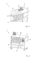
- FIG. 1 shows a tool trolley 1 for receiving a tool assortment, the tool assortment having a socket assortment 2, screwdriver 3, ring spanner 4 and open-end wrench 5.
- the workshop trolley 1 itself consists of a rollable housing 6, in which extendable drawers 7 are arranged. On the top of the housing 6 is a worktop 8.
- a tool holder 9 according to the invention for receiving the tool assortment is arranged.
- the elongated tools such as screwdriver 3, handling the socket wrench assortment 2 and wrenches 4, 5, are oriented in the direction of a vertical axis 10.
- FIG. 2 shows a detailed view of the drawer 7.
- tabs 12 are formed on the back 11 of the drawer 7, wherein the tabs 12 are coupled with not visible here engagement means on the tool holder 9, so that the tool holder 9 is fixed in position in the drawer 7.
- FIG. 3 shows a further embodiment of the workshop car 1 according to the invention, in which case the tool holder 9 is formed with a slightly tapered surface 13. This results in a more ergonomic access to the located in the tool holder 9 tool assortment.
- the tool holder 9 is further used in a recess 14 of the worktop 8. Here comes a front edge 15 of the tool holder 9 in alignment with the working surface 16 of the worktop 8 to the plant.
- FIG. 4 shows a side view of the workshop cart 1 according to FIG. 3 , where in FIG. 4 the angle ⁇ and the resulting ergonomic accessibility to the tool from a front side 17 of the workshop cart 1 will become apparent.
- FIG. 5 shows a further embodiment of the workshop car 1 according to the invention, wherein here on the worktop 8 four recesses 14 are present.
- Two recesses 14 are provided with a blanking plug 18, whereas in the other recesses 14 each insert module 9 is inserted.
- the recesses 14 are, based on the depth 19 of the worktop 8, preferably between 1 ⁇ 4 and 1 ⁇ 2 of the depth 19, formed. This ensures that there is enough residual work space to perform assembly work.
- the drawers 7 are up to a maximum of about half of the depth 19 of the worktop 7 formed.
- FIG. 6 shows a further embodiment of the present invention, in which case on the one hand on the worktop 8, a tool holder 9 with a range of tools of the working surface 16 is turned off.
- the position of the tool holder 9 can be selected individually for the respective work assembly process.
- a rack receptacle 21 is provided for inserting a tool holder 9.
- the rack mount 21 is ergonomically arranged so that it can be arranged at an angle ⁇ to the front side 18 of the workshop car 1.
- the entire working surface 16 of the worktop 8 is available to the user installer, with direct, quick access to the tool required in each case.
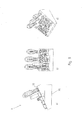
- FIG. 7 shows a tool holder according to the invention 9 in a side view in Figure 7a , a top view in FIG. 7b and a perspective view in FIG FIG. 7c , Shown in each case is the multi-layer of the tool holder 9, consisting of an upper layer 22, a first intermediate layer 23, a second intermediate layer 24 and a lower layer 25.
- Hieran are screwdriver 3, socket wrench 26, a socket wrench handle 2, Aufsteckbits 27, open-end wrench 28 and a gun 29.
- FIGS. 8a to c show an analogous embodiment variant with an inclined surface 13, wherein the surface 13 at an angle ⁇ to a working surface 30 has.
- FIG. 9 shows a tool holder 9 according to the invention for receiving elongated hand tools in a sectional view.
- screwdriver 3 4 ring spanner, extensions 31 and a ratchet 29.
- the tool holder 9 according to the invention has a Einsteckplatte 32 and is constructed in layers, so that an upper layer 22, a first intermediate layer 23, a second intermediate layer 24 and a lower layer 25 are formed.
- the hand tools arranged in the tool holder 9 according to the invention are oriented with their respective longitudinal axes in the direction of a vertical axis 10.
- the construction according to the invention of the tool holder 9 becomes clear on the right-hand side of the image, whereupon the receiving openings for a respective hand tool, passing through the individual layers, delimit the respective insertion depth 33a, 33b of a hand tool.
- the insertion depth 33a of a long extension 31 is correspondingly formed up to the second intermediate layer 24.
- the Insertion depth 33b of the short extension 31 and the ratchet 29 formed only the upper layer 22 by passing.
- FIG. 10 shows a configuration possibility of a tool holder 9 according to the invention in a plan view.
- the receiving openings 34 are configured such that they are formed for receiving a respective hand tool not shown in its cross section with different sizes. At least some of the illustrated receiving openings 34 have a cross-shaped cross-section. This results in the cross-shaped receiving openings 34 relief slots 35, which avoid lending or tearing or even a deflection of the material of the tool holder 9 according to the invention in the area surrounding the receiving opening 34 over the period of use.
- FIG. 11 shows a further embodiment, in which case at least some of the receiving openings 34 are configured in cross-section X-shaped. Also arise in the X-shaped peripheral areas relief slots 35, which prevent material fatigue of the tool holder 9 according to the invention over the period of use.
- FIG. 12 shows the plug-in plate 32 with underlying tool holder 9 in top view.
- the plug-in plate 32 has insertion openings 36 and the tool holder 9 located above receiving openings 34.
- the receiving openings 34 are each formed in their cross-sectional area slightly smaller than the insertion opening 36 of the plug-in plate 32nd This condition can due to the higher hardness of the plug-in plate 32, the tool, without coming to the insertion opening 36 to the system, are inserted through. By contrast, it comes to a positive and / or non-positive contact between the tool and receiving opening 34 of the tool holder 9. As a result, the respectively inserted hand tool is fixed in position held in the tool holder 9 according to the invention.
Landscapes
- Engineering & Computer Science (AREA)
- Mechanical Engineering (AREA)
- Workshop Equipment, Work Benches, Supports, Or Storage Means (AREA)
- Packaging Of Annular Or Rod-Shaped Articles, Wearing Apparel, Cassettes, Or The Like (AREA)
- Handcart (AREA)
- Orthopedics, Nursing, And Contraception (AREA)
- Purses, Travelling Bags, Baskets, Or Suitcases (AREA)
- Table Equipment (AREA)
Applications Claiming Priority (2)
| Application Number | Priority Date | Filing Date | Title |
|---|---|---|---|
| DE202010011399U DE202010011399U1 (de) | 2010-08-13 | 2010-08-13 | Werkstattwagen |
| DE202011003959U DE202011003959U1 (de) | 2010-08-13 | 2011-03-14 | Werkzeugaufnahme |
Publications (3)
| Publication Number | Publication Date |
|---|---|
| EP2428333A2 true EP2428333A2 (fr) | 2012-03-14 |
| EP2428333A3 EP2428333A3 (fr) | 2015-10-07 |
| EP2428333B1 EP2428333B1 (fr) | 2016-11-02 |
Family
ID=43049784
Family Applications (5)
| Application Number | Title | Priority Date | Filing Date |
|---|---|---|---|
| EP11174863.8A Not-in-force EP2428326B1 (fr) | 2010-08-13 | 2011-07-21 | Chariot atelier avec porte-outil |
| EP11174904.0A Not-in-force EP2428333B1 (fr) | 2010-08-13 | 2011-07-21 | Porte-outils |
| EP11174877.8A Withdrawn EP2428328A3 (fr) | 2010-08-13 | 2011-07-21 | Boîte à outils avec plaquette enfichable |
| EP11174856.2A Not-in-force EP2428327B1 (fr) | 2010-08-13 | 2011-07-21 | Chariot atelier |
| EP11174901.6A Withdrawn EP2428329A3 (fr) | 2010-08-13 | 2011-07-21 | Boîte à outils avec des inserts en mousse |
Family Applications Before (1)
| Application Number | Title | Priority Date | Filing Date |
|---|---|---|---|
| EP11174863.8A Not-in-force EP2428326B1 (fr) | 2010-08-13 | 2011-07-21 | Chariot atelier avec porte-outil |
Family Applications After (3)
| Application Number | Title | Priority Date | Filing Date |
|---|---|---|---|
| EP11174877.8A Withdrawn EP2428328A3 (fr) | 2010-08-13 | 2011-07-21 | Boîte à outils avec plaquette enfichable |
| EP11174856.2A Not-in-force EP2428327B1 (fr) | 2010-08-13 | 2011-07-21 | Chariot atelier |
| EP11174901.6A Withdrawn EP2428329A3 (fr) | 2010-08-13 | 2011-07-21 | Boîte à outils avec des inserts en mousse |
Country Status (5)
| Country | Link |
|---|---|
| EP (5) | EP2428326B1 (fr) |
| CN (5) | CN102424191B (fr) |
| DE (6) | DE202010011399U1 (fr) |
| ES (2) | ES2603068T3 (fr) |
| TW (5) | TW201217122A (fr) |
Cited By (1)
| Publication number | Priority date | Publication date | Assignee | Title |
|---|---|---|---|---|
| CN103637570A (zh) * | 2013-11-21 | 2014-03-19 | 南通山口精工机电有限公司 | 工具柜 |
Families Citing this family (33)
| Publication number | Priority date | Publication date | Assignee | Title |
|---|---|---|---|---|
| DE102012006257A1 (de) * | 2012-03-29 | 2013-10-02 | Gerhard Hölle | Aufnahmevorrichtung für Werkzeugpaletten |
| CN102697274A (zh) * | 2012-06-13 | 2012-10-03 | 力帆实业(集团)股份有限公司 | 返修调试工具箱 |
| CN104552194B (zh) * | 2012-11-08 | 2016-06-15 | 江苏省电力公司常州供电公司 | 一种智能绝缘工具柜使用方法 |
| CN104044129B (zh) * | 2013-03-13 | 2016-11-23 | 陈辉谦 | 工具头收纳座 |
| CN104210797A (zh) * | 2013-06-03 | 2014-12-17 | 昆山飞达磨具制造有限公司 | 砂轮片储存柜 |
| CN103522273A (zh) * | 2013-09-18 | 2014-01-22 | 沃德(天津)传动有限公司 | 一种摆放装置 |
| CN103586856A (zh) * | 2013-11-13 | 2014-02-19 | 富卓汽车内饰(安徽)有限公司 | 一种物料存放运输工装 |
| DE102014207572A1 (de) * | 2014-04-22 | 2015-10-22 | Zf Friedrichshafen Ag | Materialträger für eine Werkstatt oder Fertigungsstätte |
| CN104000401A (zh) * | 2014-06-06 | 2014-08-27 | 浙江机电职业技术学院 | 铣工定置工具柜 |
| CN104015174A (zh) * | 2014-06-19 | 2014-09-03 | 中船动力有限公司 | 专用螺杆放置柜 |
| CN104665122B (zh) * | 2015-03-06 | 2017-02-08 | 南通乐士机械有限公司 | 一种制鞋用的鞋架 |
| CN104827454A (zh) * | 2015-05-20 | 2015-08-12 | 江苏信合众泰精密机械有限公司 | 机床工具台 |
| CN105033515A (zh) * | 2015-07-14 | 2015-11-11 | 浙江新工机械制造有限公司 | 一种用于放置焊接工件的推车机构 |
| TWI564126B (zh) * | 2016-02-04 | 2017-01-01 | 7-Leaders Corp | Assembling tool pallet and its packing box |
| CN105729431B (zh) * | 2016-03-31 | 2018-06-19 | 苏州亚思科精密数控有限公司 | 一种刀具放置架 |
| CN105773263A (zh) * | 2016-03-31 | 2016-07-20 | 苏州亚思科精密数控有限公司 | 一种刀具输送装置 |
| CN105979737A (zh) * | 2016-07-25 | 2016-09-28 | 苏州市龙源电力科技股份有限公司 | 一种带有壁挂收纳箱的电气控制柜 |
| CN106695726B (zh) * | 2017-02-21 | 2023-08-18 | 浙江兴达讯智能科技有限公司 | 一种智能工具柜 |
| CN107020612A (zh) * | 2017-03-31 | 2017-08-08 | 成都协恒科技有限公司 | 一种大容量工具柜 |
| CN107009335A (zh) * | 2017-05-08 | 2017-08-04 | 江苏瑞尔光学有限公司 | 一种光学镜片转移及加工用卡架 |
| DE102017117182A1 (de) * | 2017-07-28 | 2019-01-31 | Adolf Würth Gmbh & Co Kg | Schubladenstruktur für Aufnahmekörper |
| DE102017117826A1 (de) | 2017-08-07 | 2019-02-07 | Bundesdruckerei Gmbh | Materialwagen und verfahren zur andienung von arbeitsmaterial an eine maschine |
| EP3698926A1 (fr) | 2017-10-19 | 2020-08-26 | SNA Europe Industries Iberia, S.A. | Système de fixation d'outils pour chariot porte-outils |
| CN108457464B (zh) * | 2018-06-11 | 2024-03-15 | 百川建设(广东)有限公司 | 一种建筑装修平台 |
| FR3083470B1 (fr) * | 2018-07-09 | 2020-12-25 | Berthier Etudes | Systeme de transfert et de traitement de goujons |
| CN109048824A (zh) * | 2018-08-27 | 2018-12-21 | 上海彭浦机器厂有限公司 | 一种组合式多层可接油料架 |
| DE102018007090A1 (de) * | 2018-09-07 | 2020-03-12 | Adolf Würth Gmbh & Co Kg | Werkstattwagen |
| CN109129379B (zh) * | 2018-09-18 | 2021-10-15 | 安徽工业大学 | 一种盾构机刀具用的工业存放架 |
| CN110014406A (zh) * | 2019-04-23 | 2019-07-16 | 绍兴市上虞区舜兴电力有限公司 | 一种电力线路施工用工具放置装置 |
| CN110842885A (zh) * | 2019-10-25 | 2020-02-28 | 河钢股份有限公司承德分公司 | 一种用于机械工具的收纳柜 |
| CN110605698A (zh) * | 2019-10-28 | 2019-12-24 | 苏州俊卿辉机械有限公司 | 一种抽屉式模具架 |
| CN111376219A (zh) * | 2020-04-07 | 2020-07-07 | 一汽奔腾轿车有限公司 | 动力总成柔性、模块化合装工装台 |
| DE102021110246A1 (de) * | 2021-04-22 | 2022-10-27 | Adolf Würth GmbH & Co. KG | Aufbewahrungsvorrichtung mit Halteborsten zum Halten von Werkzeug |
Family Cites Families (68)
| Publication number | Priority date | Publication date | Assignee | Title |
|---|---|---|---|---|
| US2899077A (en) * | 1959-08-11 | Compression holder for elongated | ||
| DE1716784U (de) * | 1955-12-02 | 1956-02-09 | Heidenreich & Harbeck Gmbh | Vorrichtung zum ablegen, transport und lagern von werkstuecken und werkzeugen. |
| DE1886899U (de) * | 1963-11-27 | 1964-01-30 | Gedore Werkzeugfabrik Otto Dow | Werkzeug-rolltisch. |
| US3777882A (en) * | 1971-05-20 | 1973-12-11 | D Mcintyre | Multi-tray instrument case |
| US4070075A (en) * | 1975-10-23 | 1978-01-24 | Morgan Robin H | Ammunition loading bench |
| DE2703367A1 (de) * | 1977-01-27 | 1978-08-03 | Dehm Otto | Werkzeughalterung |
| US4266835A (en) * | 1979-09-04 | 1981-05-12 | Schmidt Lavern | Compact position lock tool box |
| US4303158A (en) * | 1979-09-24 | 1981-12-01 | Perkins Donald R | Tool box |
| CH650209A5 (de) * | 1981-01-05 | 1985-07-15 | Bernhard Laeser | Behaeltnis zur sortierten aufbewahrung einer vielzahl von dichtungsringen. |
| FR2512377A1 (fr) * | 1981-09-10 | 1983-03-11 | Jantzen Eric | Coffret de rangement d'outils portatif |
| US4503972A (en) * | 1983-05-23 | 1985-03-12 | Federal-Mogul Corporation | Microdrill package |
| US4545628A (en) * | 1984-02-17 | 1985-10-08 | The Jacobs Manufacturing Co. | Tool chest with retractable step |
| GB8504016D0 (en) * | 1985-02-16 | 1985-03-20 | Coe S Derby Ltd | Storage assembly |
| FR2618365B1 (fr) * | 1987-07-20 | 1991-10-11 | Parolai Meubles Sa | Desserte de rangement et de classement d'accessoires de travail a supports de rangement mobiles symetriquement repartis |
| DE8716361U1 (de) | 1987-12-11 | 1988-01-28 | Hazet-Werk Hermann Zerver Gmbh & Co Kg, 5630 Remscheid | Vorrichtung zur Aufbewahrung von Werkzeugen, Werkstücken und Kleinmaterial, insbesondere für Kraftfahrzeugwerkstätten |
| US4826007A (en) * | 1988-05-11 | 1989-05-02 | Gary Skeie | Tool bucket organizer |
| DE8912526U1 (de) * | 1988-10-25 | 1990-02-01 | Messmer, Johannes, 7803 Gundelfingen | Aufbewahrungsvorrichtung |
| ATE112204T1 (de) * | 1989-03-31 | 1994-10-15 | Karl Hofer | Festhaltevorrichtung. |
| US4947998A (en) * | 1989-08-24 | 1990-08-14 | Smeller Donald W | Implement organizer |
| GB2247669B (en) * | 1990-09-06 | 1994-02-09 | Ronald John Clarke | Implement storage device |
| CN2097725U (zh) * | 1991-08-05 | 1992-03-04 | 曾达夫 | 组合工具盒 |
| US5207723A (en) * | 1991-09-24 | 1993-05-04 | Southern Case, Inc. | Portable sectional storage cabinet |
| US5320223A (en) * | 1993-03-19 | 1994-06-14 | Foam Cutting Engineers, Inc. | Insert having part numbers or the like printed at the bottom of retaining recesses |
| US5350065A (en) * | 1993-06-11 | 1994-09-27 | Darrey John J | Tool and hardware carrier for bucket |
| CA2190489A1 (fr) * | 1994-05-18 | 1995-11-23 | Yoshimasa Yokoyama | Materiau de base pour stratifie en carton ondule |
| US5437502A (en) * | 1994-08-03 | 1995-08-01 | Warnick; John D. | Utility holder |
| US5560480A (en) * | 1994-11-04 | 1996-10-01 | Singleton; Robert P. | Socket holder apparatus |
| US5577817A (en) * | 1995-07-31 | 1996-11-26 | Reynolds; Cory | Portable paints and supplies storage and work enclosure |
| DE19700348A1 (de) * | 1996-07-27 | 1998-01-29 | Joachim Fitzner | Werkzeugträger |
| DE29714568U1 (de) * | 1997-08-14 | 1997-10-23 | Festo Tooltechnic GmbH & Co, 73728 Esslingen | Einsatzkasten |
| US5882097A (en) * | 1997-10-02 | 1999-03-16 | Waterloo Industries, Inc. | Step tool box |
| US5951129A (en) * | 1998-01-05 | 1999-09-14 | Stein; Brad A. | Tool-box |
| US5924568A (en) * | 1998-03-26 | 1999-07-20 | Zajonc; Adam E. | Removable bucket insert for containing tools |
| US6086073A (en) * | 1998-07-22 | 2000-07-11 | Suncast Corporation | Portable work center |
| US6484892B1 (en) * | 1998-09-17 | 2002-11-26 | Randolph E. Gooner | Device for storing tools |
| US6244064B1 (en) * | 1998-11-23 | 2001-06-12 | Arthur Powell | Combination toolbox-cooler device |
| EP1281632B1 (fr) * | 2000-04-26 | 2004-09-15 | Altech Co. Ltd | Matiere de rembourrage pour emballage et procede et dispositif de fabrication de ladite matiere |
| CN2510239Y (zh) * | 2001-11-09 | 2002-09-11 | 林江河 | 六角扳手使用收藏构造 |
| US20030201699A1 (en) * | 2002-04-16 | 2003-10-30 | Chin-Chuan Hong | Tool cabinet |
| CN2651176Y (zh) * | 2002-04-22 | 2004-10-27 | 苏州宝时得电动工具有限公司 | 电动工具箱 |
| DE20301995U1 (de) * | 2003-02-08 | 2003-04-24 | Vikari, Rudolf, 97999 Igersheim | Werkstattwagen |
| CN2614863Y (zh) * | 2003-03-21 | 2004-05-12 | 陈章英 | 改进的工具箱 |
| TWM249786U (en) * | 2003-08-21 | 2004-11-11 | Shiou-Yi Chen | Improved structure for storage cabinet of hand tool |
| GB2406092B (en) * | 2003-09-17 | 2005-10-19 | Coplan Ltd | Inventory control system |
| US20060054769A1 (en) * | 2004-09-13 | 2006-03-16 | Bewsky Conrad W | Implement tip isolating and retaining mat |
| US7322470B2 (en) * | 2004-09-30 | 2008-01-29 | Black & Decker Inc. | Tool container |
| TWM274214U (en) * | 2005-03-15 | 2005-09-01 | E Make Co Ltd | Table structure of tool chest |
| US20060249412A1 (en) * | 2005-05-03 | 2006-11-09 | Hernandez Hector R | Rotary tool case |
| CN2820469Y (zh) * | 2005-05-24 | 2006-09-27 | 宜玛工业股份有限公司 | 工具箱台板结构 |
| CN2827660Y (zh) * | 2005-07-26 | 2006-10-18 | 陈霈琳 | 伸缩式工具箱 |
| CN2866023Y (zh) * | 2005-09-12 | 2007-02-07 | 林宏麟 | 工具盒连动构造 |
| DE202005018504U1 (de) | 2005-11-24 | 2006-01-26 | Hazet-Werk Hermann Zerver Gmbh & Co. Kg | Schublade und Werkstattwagen |
| US20070152415A1 (en) * | 2006-01-03 | 2007-07-05 | Gunter Robert L | Mobile apparatus for storage and transportation of lawn tools and accessories |
| CN200960658Y (zh) * | 2006-10-26 | 2007-10-17 | 宁波耀升进出口有限公司 | 一种螺丝批套工具盒 |
| CN201009235Y (zh) * | 2007-03-13 | 2008-01-23 | 江苏通润工具箱柜股份有限公司 | 一种方便拆装型组合工具箱 |
| CN201026608Y (zh) * | 2007-04-11 | 2008-02-27 | 陈润钊 | 金属工具套箱 |
| GB0716108D0 (en) * | 2007-08-17 | 2007-09-26 | Zeroshift Ltd | Inventory control system |
| ATE523300T1 (de) | 2007-10-05 | 2011-09-15 | Digipack Ag | Verfahren zur konfiguration von einsätzen für behälter für lagerobjekte sowie konfigurationssystem |
| DE202007017306U1 (de) * | 2007-12-12 | 2008-03-20 | Lin, Chia-Yun | Schrank mit Stoßleisten |
| NL2001409C2 (nl) * | 2008-03-27 | 2009-09-29 | Hui-Chen Liao | Gereedschapskast. |
| DE202008004969U1 (de) * | 2008-04-09 | 2008-06-26 | CHIN FWU CHERN INTERNATIONAL CO., LTD., Taiping City | Werkzeugbox |
| US7854321B2 (en) * | 2008-07-01 | 2010-12-21 | The Stanley Works Israel Ltd. | Rolling container assembly |
| CN201287329Y (zh) * | 2008-09-09 | 2009-08-12 | 杭州巨星科技股份有限公司 | 组合式工具头座 |
| CN201271886Y (zh) * | 2008-09-25 | 2009-07-15 | 吴向阳 | 螺丝批插架 |
| CN201357408Y (zh) * | 2009-01-08 | 2009-12-09 | 包剑刚 | 一种工具车 |
| CN201471429U (zh) * | 2009-07-17 | 2010-05-19 | 谢翠斌 | 带工具箱凳的组合服务车 |
| CN101664921A (zh) * | 2009-09-29 | 2010-03-10 | 秦贞坤 | 一种工作台用便捷工具支架 |
| TWM385455U (en) * | 2010-04-13 | 2010-08-01 | Ersson Internat Blow Mold Manufacturer Co Ltd | A tool positioning pad having metallic surface coatings |
-
2010
- 2010-08-13 DE DE202010011399U patent/DE202010011399U1/de not_active Expired - Lifetime
-
2011
- 2011-03-14 DE DE202011003926U patent/DE202011003926U1/de not_active Expired - Lifetime
- 2011-03-14 DE DE202011003958U patent/DE202011003958U1/de not_active Expired - Lifetime
- 2011-03-14 DE DE202011003959U patent/DE202011003959U1/de not_active Expired - Lifetime
- 2011-03-14 DE DE202011003957U patent/DE202011003957U1/de not_active Expired - Lifetime
- 2011-03-14 DE DE202011003925U patent/DE202011003925U1/de not_active Expired - Lifetime
- 2011-07-21 EP EP11174863.8A patent/EP2428326B1/fr not_active Not-in-force
- 2011-07-21 EP EP11174904.0A patent/EP2428333B1/fr not_active Not-in-force
- 2011-07-21 ES ES11174863.8T patent/ES2603068T3/es active Active
- 2011-07-21 ES ES11174904.0T patent/ES2605243T3/es active Active
- 2011-07-21 EP EP11174877.8A patent/EP2428328A3/fr not_active Withdrawn
- 2011-07-21 EP EP11174856.2A patent/EP2428327B1/fr not_active Not-in-force
- 2011-07-21 EP EP11174901.6A patent/EP2428329A3/fr not_active Withdrawn
- 2011-08-05 CN CN201110223173.6A patent/CN102424191B/zh not_active Expired - Fee Related
- 2011-08-05 CN CN201110223171.7A patent/CN102380864B/zh not_active Expired - Fee Related
- 2011-08-05 CN CN2011102231793A patent/CN102380860A/zh active Pending
- 2011-08-08 CN CN201110224657.2A patent/CN102371579B/zh not_active Expired - Fee Related
- 2011-08-08 CN CN201110224658.7A patent/CN102371580B/zh not_active Expired - Fee Related
- 2011-08-12 TW TW100128958A patent/TW201217122A/zh unknown
- 2011-08-12 TW TW100128955A patent/TW201217121A/zh unknown
- 2011-08-12 TW TW100128959A patent/TWI508830B/zh not_active IP Right Cessation
- 2011-08-12 TW TW100128960A patent/TW201217115A/zh unknown
- 2011-08-12 TW TW100128954A patent/TWI511851B/zh not_active IP Right Cessation
Non-Patent Citations (1)
| Title |
|---|
| None |
Cited By (1)
| Publication number | Priority date | Publication date | Assignee | Title |
|---|---|---|---|---|
| CN103637570A (zh) * | 2013-11-21 | 2014-03-19 | 南通山口精工机电有限公司 | 工具柜 |
Also Published As
Similar Documents
| Publication | Publication Date | Title |
|---|---|---|
| EP2428333B1 (fr) | Porte-outils | |
| EP3283260B1 (fr) | Boîte d'assortiment et ensemble comportant au moins une boîte d'assortiment et une bande de retenue | |
| DE102016112854A1 (de) | Stapelbarer Systembehälter | |
| DE102017125121B4 (de) | Aufbewahrungsvorrichtung | |
| EP1777042A1 (fr) | Dispositif pour le logement de lames de tournevis | |
| EP2308651B1 (fr) | Machine-outil manuelle dotée d'un crochet | |
| EP2301724B1 (fr) | Dispositif distributeur | |
| DE202011003956U1 (de) | Werkbank mit Werkzeugaufnahme | |
| EP2853664B1 (fr) | Poignée de porte | |
| EP3658337B1 (fr) | Structure de tiroir pour corps de logement | |
| DE102012010337A1 (de) | Anordnung eines Karosserieteils und eines Behältersbei einem Kraftfahrzeug | |
| WO2012048796A2 (fr) | Dispositif pour guider et maintenir des câbles | |
| EP3620267A1 (fr) | Chariot d'atelier | |
| DE102023100625A1 (de) | Möbel- oder Haushaltsgeräteelement und Verfahren zur Montage eines Möbel- oder Haushaltsgeräteelements | |
| DE202017106661U1 (de) | Schraubendreher | |
| WO1995023052A1 (fr) | Tournevis a main | |
| DE102011100704A1 (de) | Befestigungsadapter für ein Reserverad eines Fahrzeugs und Befestigungseinrichtung | |
| DE202019101848U1 (de) | Stationswagen mit austauschbaren Schubladen | |
| DE102012108687A1 (de) | Vorrichtung zur Halterung eines Regalelements in einem Fahrzeug wie einem Kastenwagen oder einem LKW mit Kofferaufbauten | |
| DE102009030895A1 (de) | Befestigungseinrichtung | |
| DE202019103362U1 (de) | Griffanordnung für ein bewegbares Objekt sowie bewegbares Objekt mit der Griffanordnung | |
| EP2508306A1 (fr) | Coffre à outils déployable | |
| DE102014104046A1 (de) | Halterungsanordnung für Werkzeuge | |
| DE29710340U1 (de) | Mehrzweckwagen oder Mehrzwecktischgestell | |
| DE102009042408A1 (de) | Handwerkzeug mit mehreren Werkzeugansätzen |
Legal Events
| Date | Code | Title | Description |
|---|---|---|---|
| AK | Designated contracting states |
Kind code of ref document: A2 Designated state(s): AL AT BE BG CH CY CZ DE DK EE ES FI FR GB GR HR HU IE IS IT LI LT LU LV MC MK MT NL NO PL PT RO RS SE SI SK SM TR |
|
| AX | Request for extension of the european patent |
Extension state: BA ME |
|
| PUAI | Public reference made under article 153(3) epc to a published international application that has entered the european phase |
Free format text: ORIGINAL CODE: 0009012 |
|
| PUAL | Search report despatched |
Free format text: ORIGINAL CODE: 0009013 |
|
| AK | Designated contracting states |
Kind code of ref document: A3 Designated state(s): AL AT BE BG CH CY CZ DE DK EE ES FI FR GB GR HR HU IE IS IT LI LT LU LV MC MK MT NL NO PL PT RO RS SE SI SK SM TR |
|
| AX | Request for extension of the european patent |
Extension state: BA ME |
|
| RIC1 | Information provided on ipc code assigned before grant |
Ipc: B25H 3/06 20060101AFI20150831BHEP Ipc: B25H 3/00 20060101ALI20150831BHEP |
|
| 17P | Request for examination filed |
Effective date: 20160406 |
|
| REG | Reference to a national code |
Ref country code: DE Ref legal event code: R079 Ref document number: 502011011035 Country of ref document: DE Free format text: PREVIOUS MAIN CLASS: B25H0003060000 Ipc: B25H0003020000 |
|
| GRAP | Despatch of communication of intention to grant a patent |
Free format text: ORIGINAL CODE: EPIDOSNIGR1 |
|
| RIC1 | Information provided on ipc code assigned before grant |
Ipc: B25H 3/02 20060101AFI20160621BHEP |
|
| INTG | Intention to grant announced |
Effective date: 20160706 |
|
| GRAS | Grant fee paid |
Free format text: ORIGINAL CODE: EPIDOSNIGR3 |
|
| GRAJ | Information related to disapproval of communication of intention to grant by the applicant or resumption of examination proceedings by the epo deleted |
Free format text: ORIGINAL CODE: EPIDOSDIGR1 |
|
| GRAL | Information related to payment of fee for publishing/printing deleted |
Free format text: ORIGINAL CODE: EPIDOSDIGR3 |
|
| GRAR | Information related to intention to grant a patent recorded |
Free format text: ORIGINAL CODE: EPIDOSNIGR71 |
|
| GRAA | (expected) grant |
Free format text: ORIGINAL CODE: 0009210 |
|
| INTC | Intention to grant announced (deleted) | ||
| AK | Designated contracting states |
Kind code of ref document: B1 Designated state(s): AL AT BE BG CH CY CZ DE DK EE ES FI FR GB GR HR HU IE IS IT LI LT LU LV MC MK MT NL NO PL PT RO RS SE SI SK SM TR |
|
| INTG | Intention to grant announced |
Effective date: 20160927 |
|
| REG | Reference to a national code |
Ref country code: GB Ref legal event code: FG4D Free format text: NOT ENGLISH |
|
| REG | Reference to a national code |
Ref country code: AT Ref legal event code: REF Ref document number: 841354 Country of ref document: AT Kind code of ref document: T Effective date: 20161115 Ref country code: CH Ref legal event code: EP |
|
| REG | Reference to a national code |
Ref country code: IE Ref legal event code: FG4D Free format text: LANGUAGE OF EP DOCUMENT: GERMAN |
|
| REG | Reference to a national code |
Ref country code: NL Ref legal event code: FP |
|
| REG | Reference to a national code |
Ref country code: DE Ref legal event code: R096 Ref document number: 502011011035 Country of ref document: DE |
|
| PG25 | Lapsed in a contracting state [announced via postgrant information from national office to epo] |
Ref country code: LV Free format text: LAPSE BECAUSE OF FAILURE TO SUBMIT A TRANSLATION OF THE DESCRIPTION OR TO PAY THE FEE WITHIN THE PRESCRIBED TIME-LIMIT Effective date: 20161102 |
|
| REG | Reference to a national code |
Ref country code: LT Ref legal event code: MG4D |
|
| REG | Reference to a national code |
Ref country code: ES Ref legal event code: FG2A Ref document number: 2605243 Country of ref document: ES Kind code of ref document: T3 Effective date: 20170313 |
|
| PG25 | Lapsed in a contracting state [announced via postgrant information from national office to epo] |
Ref country code: GR Free format text: LAPSE BECAUSE OF FAILURE TO SUBMIT A TRANSLATION OF THE DESCRIPTION OR TO PAY THE FEE WITHIN THE PRESCRIBED TIME-LIMIT Effective date: 20170203 Ref country code: NO Free format text: LAPSE BECAUSE OF FAILURE TO SUBMIT A TRANSLATION OF THE DESCRIPTION OR TO PAY THE FEE WITHIN THE PRESCRIBED TIME-LIMIT Effective date: 20170202 Ref country code: SE Free format text: LAPSE BECAUSE OF FAILURE TO SUBMIT A TRANSLATION OF THE DESCRIPTION OR TO PAY THE FEE WITHIN THE PRESCRIBED TIME-LIMIT Effective date: 20161102 Ref country code: LT Free format text: LAPSE BECAUSE OF FAILURE TO SUBMIT A TRANSLATION OF THE DESCRIPTION OR TO PAY THE FEE WITHIN THE PRESCRIBED TIME-LIMIT Effective date: 20161102 |
|
| PG25 | Lapsed in a contracting state [announced via postgrant information from national office to epo] |
Ref country code: IS Free format text: LAPSE BECAUSE OF FAILURE TO SUBMIT A TRANSLATION OF THE DESCRIPTION OR TO PAY THE FEE WITHIN THE PRESCRIBED TIME-LIMIT Effective date: 20170302 Ref country code: PT Free format text: LAPSE BECAUSE OF FAILURE TO SUBMIT A TRANSLATION OF THE DESCRIPTION OR TO PAY THE FEE WITHIN THE PRESCRIBED TIME-LIMIT Effective date: 20170302 Ref country code: PL Free format text: LAPSE BECAUSE OF FAILURE TO SUBMIT A TRANSLATION OF THE DESCRIPTION OR TO PAY THE FEE WITHIN THE PRESCRIBED TIME-LIMIT Effective date: 20161102 Ref country code: FI Free format text: LAPSE BECAUSE OF FAILURE TO SUBMIT A TRANSLATION OF THE DESCRIPTION OR TO PAY THE FEE WITHIN THE PRESCRIBED TIME-LIMIT Effective date: 20161102 Ref country code: RS Free format text: LAPSE BECAUSE OF FAILURE TO SUBMIT A TRANSLATION OF THE DESCRIPTION OR TO PAY THE FEE WITHIN THE PRESCRIBED TIME-LIMIT Effective date: 20161102 Ref country code: HR Free format text: LAPSE BECAUSE OF FAILURE TO SUBMIT A TRANSLATION OF THE DESCRIPTION OR TO PAY THE FEE WITHIN THE PRESCRIBED TIME-LIMIT Effective date: 20161102 |
|
| REG | Reference to a national code |
Ref country code: FR Ref legal event code: PLFP Year of fee payment: 7 |
|
| PG25 | Lapsed in a contracting state [announced via postgrant information from national office to epo] |
Ref country code: RO Free format text: LAPSE BECAUSE OF FAILURE TO SUBMIT A TRANSLATION OF THE DESCRIPTION OR TO PAY THE FEE WITHIN THE PRESCRIBED TIME-LIMIT Effective date: 20161102 Ref country code: DK Free format text: LAPSE BECAUSE OF FAILURE TO SUBMIT A TRANSLATION OF THE DESCRIPTION OR TO PAY THE FEE WITHIN THE PRESCRIBED TIME-LIMIT Effective date: 20161102 Ref country code: EE Free format text: LAPSE BECAUSE OF FAILURE TO SUBMIT A TRANSLATION OF THE DESCRIPTION OR TO PAY THE FEE WITHIN THE PRESCRIBED TIME-LIMIT Effective date: 20161102 Ref country code: SK Free format text: LAPSE BECAUSE OF FAILURE TO SUBMIT A TRANSLATION OF THE DESCRIPTION OR TO PAY THE FEE WITHIN THE PRESCRIBED TIME-LIMIT Effective date: 20161102 Ref country code: CZ Free format text: LAPSE BECAUSE OF FAILURE TO SUBMIT A TRANSLATION OF THE DESCRIPTION OR TO PAY THE FEE WITHIN THE PRESCRIBED TIME-LIMIT Effective date: 20161102 |
|
| REG | Reference to a national code |
Ref country code: DE Ref legal event code: R097 Ref document number: 502011011035 Country of ref document: DE |
|
| PG25 | Lapsed in a contracting state [announced via postgrant information from national office to epo] |
Ref country code: SM Free format text: LAPSE BECAUSE OF FAILURE TO SUBMIT A TRANSLATION OF THE DESCRIPTION OR TO PAY THE FEE WITHIN THE PRESCRIBED TIME-LIMIT Effective date: 20161102 Ref country code: BG Free format text: LAPSE BECAUSE OF FAILURE TO SUBMIT A TRANSLATION OF THE DESCRIPTION OR TO PAY THE FEE WITHIN THE PRESCRIBED TIME-LIMIT Effective date: 20170202 |
|
| PLBE | No opposition filed within time limit |
Free format text: ORIGINAL CODE: 0009261 |
|
| STAA | Information on the status of an ep patent application or granted ep patent |
Free format text: STATUS: NO OPPOSITION FILED WITHIN TIME LIMIT |
|
| PGFP | Annual fee paid to national office [announced via postgrant information from national office to epo] |
Ref country code: NL Payment date: 20170719 Year of fee payment: 7 |
|
| 26N | No opposition filed |
Effective date: 20170803 |
|
| PGFP | Annual fee paid to national office [announced via postgrant information from national office to epo] |
Ref country code: GB Payment date: 20170719 Year of fee payment: 7 Ref country code: FR Payment date: 20170724 Year of fee payment: 7 Ref country code: IT Payment date: 20170728 Year of fee payment: 7 Ref country code: ES Payment date: 20170825 Year of fee payment: 7 |
|
| PG25 | Lapsed in a contracting state [announced via postgrant information from national office to epo] |
Ref country code: SI Free format text: LAPSE BECAUSE OF FAILURE TO SUBMIT A TRANSLATION OF THE DESCRIPTION OR TO PAY THE FEE WITHIN THE PRESCRIBED TIME-LIMIT Effective date: 20161102 |
|
| PGFP | Annual fee paid to national office [announced via postgrant information from national office to epo] |
Ref country code: BE Payment date: 20170719 Year of fee payment: 7 |
|
| REG | Reference to a national code |
Ref country code: CH Ref legal event code: PL |
|
| REG | Reference to a national code |
Ref country code: IE Ref legal event code: MM4A |
|
| PG25 | Lapsed in a contracting state [announced via postgrant information from national office to epo] |
Ref country code: LI Free format text: LAPSE BECAUSE OF NON-PAYMENT OF DUE FEES Effective date: 20170731 Ref country code: IE Free format text: LAPSE BECAUSE OF NON-PAYMENT OF DUE FEES Effective date: 20170721 Ref country code: CH Free format text: LAPSE BECAUSE OF NON-PAYMENT OF DUE FEES Effective date: 20170731 |
|
| PG25 | Lapsed in a contracting state [announced via postgrant information from national office to epo] |
Ref country code: LU Free format text: LAPSE BECAUSE OF NON-PAYMENT OF DUE FEES Effective date: 20170721 |
|
| REG | Reference to a national code |
Ref country code: AT Ref legal event code: MM01 Ref document number: 841354 Country of ref document: AT Kind code of ref document: T Effective date: 20170721 |
|
| PG25 | Lapsed in a contracting state [announced via postgrant information from national office to epo] |
Ref country code: MT Free format text: LAPSE BECAUSE OF FAILURE TO SUBMIT A TRANSLATION OF THE DESCRIPTION OR TO PAY THE FEE WITHIN THE PRESCRIBED TIME-LIMIT Effective date: 20161102 |
|
| PG25 | Lapsed in a contracting state [announced via postgrant information from national office to epo] |
Ref country code: AT Free format text: LAPSE BECAUSE OF NON-PAYMENT OF DUE FEES Effective date: 20170721 |
|
| REG | Reference to a national code |
Ref country code: NL Ref legal event code: MM Effective date: 20180801 |
|
| GBPC | Gb: european patent ceased through non-payment of renewal fee |
Effective date: 20180721 |
|
| REG | Reference to a national code |
Ref country code: BE Ref legal event code: MM Effective date: 20180731 |
|
| PG25 | Lapsed in a contracting state [announced via postgrant information from national office to epo] |
Ref country code: FR Free format text: LAPSE BECAUSE OF NON-PAYMENT OF DUE FEES Effective date: 20180731 Ref country code: GB Free format text: LAPSE BECAUSE OF NON-PAYMENT OF DUE FEES Effective date: 20180721 |
|
| PG25 | Lapsed in a contracting state [announced via postgrant information from national office to epo] |
Ref country code: BE Free format text: LAPSE BECAUSE OF NON-PAYMENT OF DUE FEES Effective date: 20180731 Ref country code: NL Free format text: LAPSE BECAUSE OF NON-PAYMENT OF DUE FEES Effective date: 20180801 |
|
| PG25 | Lapsed in a contracting state [announced via postgrant information from national office to epo] |
Ref country code: MC Free format text: LAPSE BECAUSE OF FAILURE TO SUBMIT A TRANSLATION OF THE DESCRIPTION OR TO PAY THE FEE WITHIN THE PRESCRIBED TIME-LIMIT Effective date: 20161102 Ref country code: HU Free format text: LAPSE BECAUSE OF FAILURE TO SUBMIT A TRANSLATION OF THE DESCRIPTION OR TO PAY THE FEE WITHIN THE PRESCRIBED TIME-LIMIT; INVALID AB INITIO Effective date: 20110721 |
|
| PG25 | Lapsed in a contracting state [announced via postgrant information from national office to epo] |
Ref country code: IT Free format text: LAPSE BECAUSE OF NON-PAYMENT OF DUE FEES Effective date: 20180721 |
|
| REG | Reference to a national code |
Ref country code: ES Ref legal event code: FD2A Effective date: 20190917 |
|
| PG25 | Lapsed in a contracting state [announced via postgrant information from national office to epo] |
Ref country code: ES Free format text: LAPSE BECAUSE OF NON-PAYMENT OF DUE FEES Effective date: 20180722 Ref country code: CY Free format text: LAPSE BECAUSE OF NON-PAYMENT OF DUE FEES Effective date: 20161102 |
|
| PGFP | Annual fee paid to national office [announced via postgrant information from national office to epo] |
Ref country code: DE Payment date: 20190730 Year of fee payment: 9 |
|
| PG25 | Lapsed in a contracting state [announced via postgrant information from national office to epo] |
Ref country code: MK Free format text: LAPSE BECAUSE OF FAILURE TO SUBMIT A TRANSLATION OF THE DESCRIPTION OR TO PAY THE FEE WITHIN THE PRESCRIBED TIME-LIMIT Effective date: 20161102 |
|
| PG25 | Lapsed in a contracting state [announced via postgrant information from national office to epo] |
Ref country code: TR Free format text: LAPSE BECAUSE OF FAILURE TO SUBMIT A TRANSLATION OF THE DESCRIPTION OR TO PAY THE FEE WITHIN THE PRESCRIBED TIME-LIMIT Effective date: 20161102 |
|
| PG25 | Lapsed in a contracting state [announced via postgrant information from national office to epo] |
Ref country code: AL Free format text: LAPSE BECAUSE OF FAILURE TO SUBMIT A TRANSLATION OF THE DESCRIPTION OR TO PAY THE FEE WITHIN THE PRESCRIBED TIME-LIMIT Effective date: 20161102 |
|
| REG | Reference to a national code |
Ref country code: DE Ref legal event code: R119 Ref document number: 502011011035 Country of ref document: DE |
|
| PG25 | Lapsed in a contracting state [announced via postgrant information from national office to epo] |
Ref country code: DE Free format text: LAPSE BECAUSE OF NON-PAYMENT OF DUE FEES Effective date: 20210202 |