EP2403981B2 - Offenend-rotorspinnvorrichtung - Google Patents
Offenend-rotorspinnvorrichtung Download PDFInfo
- Publication number
- EP2403981B2 EP2403981B2 EP10705298.7A EP10705298A EP2403981B2 EP 2403981 B2 EP2403981 B2 EP 2403981B2 EP 10705298 A EP10705298 A EP 10705298A EP 2403981 B2 EP2403981 B2 EP 2403981B2
- Authority
- EP
- European Patent Office
- Prior art keywords
- channel
- component
- channel portion
- open
- rotor
- Prior art date
- Legal status (The legal status is an assumption and is not a legal conclusion. Google has not performed a legal analysis and makes no representation as to the accuracy of the status listed.)
- Active
Links
- 238000007383 open-end spinning Methods 0.000 title claims description 20
- 239000000835 fiber Substances 0.000 claims description 36
- 238000009987 spinning Methods 0.000 claims description 25
- 238000007789 sealing Methods 0.000 claims description 8
- 230000015572 biosynthetic process Effects 0.000 description 2
- 238000010276 construction Methods 0.000 description 2
- 230000007704 transition Effects 0.000 description 2
- 235000013351 cheese Nutrition 0.000 description 1
- 239000003795 chemical substances by application Substances 0.000 description 1
- 230000001419 dependent effect Effects 0.000 description 1
- 238000005516 engineering process Methods 0.000 description 1
- 238000009434 installation Methods 0.000 description 1
- 239000000565 sealant Substances 0.000 description 1
- 239000004753 textile Substances 0.000 description 1
Images

Classifications
-
- D—TEXTILES; PAPER
- D01—NATURAL OR MAN-MADE THREADS OR FIBRES; SPINNING
- D01H—SPINNING OR TWISTING
- D01H4/00—Open-end spinning machines or arrangements for imparting twist to independently moving fibres separated from slivers; Piecing arrangements therefor; Covering endless core threads with fibres by open-end spinning techniques
- D01H4/04—Open-end spinning machines or arrangements for imparting twist to independently moving fibres separated from slivers; Piecing arrangements therefor; Covering endless core threads with fibres by open-end spinning techniques imparting twist by contact of fibres with a running surface
- D01H4/08—Rotor spinning, i.e. the running surface being provided by a rotor
-
- D—TEXTILES; PAPER
- D01—NATURAL OR MAN-MADE THREADS OR FIBRES; SPINNING
- D01H—SPINNING OR TWISTING
- D01H4/00—Open-end spinning machines or arrangements for imparting twist to independently moving fibres separated from slivers; Piecing arrangements therefor; Covering endless core threads with fibres by open-end spinning techniques
- D01H4/38—Channels for feeding fibres to the yarn forming region
Definitions
- the invention relates to an open-end rotor spinning device according to the preamble of claim 1.
- open-end rotor spinning devices have a spinning rotor that rotates during the high-speed spinning process in a vacuum-pressurized rotor housing.
- the forwardly open itself to the rotor housing is hermetically sealed during the spinning process by a cover element, in which a replaceable channel plate adapter is embedded.
- the lid member usually also has a Auflensewalzengephase and bearing brackets for an opening roller and a Faserbandzu USAlinder, and is connected via a pivot axis which is arranged orthogonal to the axes of rotation of the opening roller and Faserbandzu Fightingzylinder limited movably connected to an associated spin box housing, for example, the storage and having the drive for the spinning rotor.
- an associated spin box housing for example, the storage and having the drive for the spinning rotor.
- the individual fibers which are combed out of the opening roller from a master fiber sliver are conveyed via a so-called fiber guide channel to the revolving spinning rotor and are spun by this into a continuously removable thread.
- the Faserleitkanäle these known open-end rotor spinning devices are usually formed in two parts. That is, usually in a bearing bore of the opening roller housing a Faserleitkanalprin is arranged, which has the input-side channel portion of a Faserleitkanals, while the output-side channel portion of the Faserleitkanals is disposed within an interchangeable Kanalplattenadapters, as mentioned above, in a corresponding receptacle in the lid member can be fixed is.
- open-end spinning devices which are each equipped with a two-part Faserleitkanal.
- An input-side channel section arranged in a fiber guide channel insert which is fixed in a bearing bore of the opening roller housing and an output-side channel section of a fiber guide channel arranged in the cover element or in a channel plate adapter are arranged such that the central longitudinal lines of the channel sections are inclined relative to one another at an advantageous angle.
- An open-end spinning device with a Faserleitkanal having inclined channel sections is also the subject of EP 0 311 988 A1 ,
- an open-end spinning device is described in which the input region of a fiber guide channel is incorporated into an opening roller housing and the associated output region of the fiber guide channel is part of a channel plate.
- the angle of inclination between the input region of a fiber guide channel which is permanently integrated in the dissolving wafer housing and the exit region of a fiber guide channel arranged in the channel plate is thereby somewhat relieved that the output region of the fiber guide channel arranged in the channel plate is provided with an additional inclination angle.
- the present invention seeks to provide an open-end rotor spinning device of the type described above, with a Faserleitkanal, the formation of which allows a simple way to optimize the fiber feed to the fiber sliding surface of a spinning rotor.
- An open-end rotor spinning device with a Faserleitkanalcommun which is fixed in a bearing bore of an opening roller housing and in which the second channel portion part extends with respect to a to the outer wall of the Faserleitkanalcommunes parallel reference line at an angle of inclination, the angle of inclination is tuned to the particular channel plate adapter used, in particular Advantage that even after replacement of the spinning rotor and the channel plate adapter, for example due to a change of yarn, by using a suitable Faserleitkanal conses can be ensured in a simple and inexpensive manner that between the channel sections a suitable inclination angle is given and thus in the fiber guide channel optimal flow conditions are given, at the same time ensuring optimum fiber feed to the fiber slipper surface of the spinning rotor.
- the Faserleitkanallang is designed as a two-part component.
- the fixable in a bearing bore of the opening roller housing first component has the first channel portion portion and the easily replaceable fixable to this first component second component is equipped with the second channel portion portion which is inclined relative to the first channel portion portion of the first component.
- the inclination of the channel section part of the second component is in each case matched exactly to a specific channel plate adapter. This means that in a spin agent change with channel plate adapter replacement can be adapted to the new circumstances by a corresponding change of the second component of the Faserleitkanalconses easily the Faserleitkanal the open-end spinning device.
- the second component can be easily connected to the first component via a connecting flange.
- the connection flange has a groove for receiving a sealant.
- the connection flange prevents, in particular in conjunction with a corresponding sealing means, preferably an O-seal, that false air can enter the Faserleitkanal. That is, it can be ensured by the connection flange that within the channel section parts of the fiber guide channel a largely undisturbed Saugluftströmung is pending, which is essential for a uniform pneumatic transport of the combed out by the opening roller individual fibers.
- Faserleitkanal even in a two-part Faserleitkanalcommun the second component of Faserleitkanalconses in the exit region of the channel portion has a concave curved sealing surface. As already explained in connection with a one-piece Faserleitkanalirri, this sealing surface corresponds with an associated channel plate adapter and ensures that in the transition region between the channel sections a clean pneumatic transition is given.
- open-end rotor spinning device carries the total number 1.
- Such open-end rotor spinning devices have, as is known, a rotor housing 2, in which the spinning cup of a spinning rotor 3, which is supported with its rotor shaft 4 in the bearing gusset of a support disk bearing 5, rotates at high speed.
- the rotor shaft 4 of the spinning rotor 3 is acted upon by a machine-long tangential belt 6, which is made by a pressure roller 7.
- the axial fixation of the rotor shaft 4 on the support disk bearing 5 preferably takes place via a permanent magnetic thrust bearing 18.
- the rotor housing 2, which is open towards the front, is closed during the spinning operation by a pivotably mounted cover element 8 into which a seal 9 is embedded.
- the rotor housing 2 is also connected via a corresponding suction line 10 to a vacuum source 11, which generates the necessary spin pressure in the rotor housing 2.
- a channel plate adapter 12 is arranged in a receptacle, which has the thread withdrawal nozzle 13, the outlet-side channel section 26 of a fiber guide channel 14 and the mouth region 27 of the fiber guide channel 14.
- a thread withdrawal tube 15 connects.
- an opening roller housing 17 is fixed to the lid member 8, which is mounted rotatably limited about a pivot axis 16.
- the cover element 8 furthermore has bearing brackets 19, 20 arranged at the rear for supporting an opening roller 21 or a sliver feed cylinder 22.
- the opening roller 21 is either driven by a single motor or, as shown in the exemplary embodiment, driven in the region of its whorl 23 by a rotating, machine-long tangential 24.
- the drive of the sliver feed cylinder 22 can be done on a single motor or it is a worm gear assembly is provided, which is connected to a machine-length drive shaft 25.
- the disintegrated in the opening roller 17 by the opening roller 21 from a (not shown) original fiber tape single fibers are fed via the fiber guide 14 on the rotating at high speed spinning rotor 3, spun into a thread and then, as usual, wound into a cheese.
- the fiber guide channel 14 has at least two channel sections 26, 28, wherein the outlet-side channel section 26 in the Channel plate adapter 12 is integrated.
- the input-side channel section 28 is part of a Faserleitkanalcicacies 30 which can be fixed in a bearing bore of the opening roller housing 17.
- the Faserleitkanalcommun 30 is formed in two parts. That is, the Faserleitkanalprin 30 consists of a first component 31 with a channel portion portion 28A and a fixable on the first component 31 second component 32 with a channel portion portion 28B.
- the second component 32 in this case has a connection flange 33 with a groove 34, in which a sealing means, preferably an O-ring seal 35, is fixed.
- the second component 32 with the connection flange 33 in such a manner in a connection opening 37 of the first member 31 that the channel portion parts 28 A and 28 B form a pneumatically continuous, input-side channel portion 28.
- the channel section part 28A in the first component 31 runs parallel to a reference line 29 arranged parallel to the outer wall of the component 31, while the channel section part 28B in the second component 32 is inclined at an angle ⁇ with respect to the reference line 29 arranged parallel to the outer wall 29 of the component 32 ,
- the input-side channel portion 28 consisting of the channel portion parts 28A and 28B starts as shown in FIG Fig.
- Faserleitkanalprin 30 input side channel portion 28 of the fiber guide 14 goes forming an advantageous angle of inclination in the integrated in the channel plate adapter 12 output-side channel portion 26 of the fiber guide 14 via.
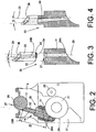
- a not covered by the claim training a Faserleitkanalcons 30 is in the Fig. 4 shown.
- the Faserleitkanalcommun 30 is integrally formed, wherein the arranged within the Faserleitkanalprines 30 input side channel portion 28 with respect to the outer wall of the Faserleitkanalprines 30 parallel reference line 29 is inclined at an angle ß. Also in this embodiment, the input-side channel portion 28 of the fiber guide 14 begins with a small distance to the periphery of the opening roller 21 and ends in the region of a sealing surface 36, which corresponds to an associated channel plate adapter 12.
Landscapes
- Engineering & Computer Science (AREA)
- Mechanical Engineering (AREA)
- Textile Engineering (AREA)
- Spinning Or Twisting Of Yarns (AREA)
Description
- Die Erfindung betrifft eine Offenend-Rotorspinnvorrichtung gemäß dem Oberbegriff des Anspruches 1.
- Wie in der Textilmaschinenindustrie bekannt und in zahlreichen Patentschriften beschrieben, verfügen Offenend-Rotorspinn-vorrichtungen über einen Spinnrotor, der während des Spinnprozesses mit hoher Drehzahl in einem unterdruckbeaufschlagten Rotorgehäuse umläuft.
Das nach vorne hin an sich offene Rotorgehäuse ist während des Spinnprozesses durch ein Deckelelement luftdicht verschlossen, in das ein auswechselbarer Kanalplattenadapter eingelassen ist. Das Deckelelement verfügt in der Regel außerdem über ein Auflösewalzengehäuse sowie Lagerkonsolen für eine Auflösewalze und einen Faserbandzuführzylinder, und ist über eine Schwenkachse, die orthogonal zu den Rotationsachsen von Auflösewalze und Faserbandzuführzylinder angeordnet ist, begrenzt beweglich mit einem zugehörigen Spinnboxgehäuse verbunden, das beispielsweise die Lagerung und den Antrieb für den Spinnrotor aufweist. In solchen Offenend-Rotorspinnvorrichtungen werden die von der Auflösewalze aus einem Vorlage-Faserband ausgekämmten Einzelfasern über einen sogenannten Faserleitkanal zum umlaufenden Spinnrotor befördert und von diesem zu einem fortlaufend abziehbaren Faden versponnen. - Die Faserleitkanäle dieser bekannten Offenend-Rotorspinnvorrichtungen sind meistens zweiteilig ausgebildet. Das heißt, in der Regel ist in einer Lagerbohrung des Auflösewalzengehäuses ein Faserleitkanaleinsatz angeordnet, der den eingangsseitigen Kanalabschnitt eines Faserleitkanals aufweist, während der ausgangsseitige Kanalabschnitt des Faserleitkanals innerhalb eines auswechselbaren Kanalplattenadapters angeordnet ist, der, wie vorstehend erwähnt, in einer entsprechenden Aufnahme im Deckelelement festlegbar ist.
- Während des Betriebes reicht der in der Aufnahme des Deckelelementes lagegenau fixierte, bei Bedarf auswechselbare Kanalplattenadapter, der neben dem ausgangsseitigen Kanalabschnitt des Faserleitkanals auch eine Durchgangsbohrung zum Festlegen einer Fadenabzugsdüse aufweist, mit einem turmartigen Vorsatz in den umlaufenden Spinnrotor.
- Im Zusammenhang mit Offenend-Rotorspinnvorrichtungen ist es außerdem seit langem bekannt, dass, um Offenend-Garne von guter Qualität herstellen zu können, gewisse Randbedingungen, beispielsweise bezüglich der gegenseitigen Anordnung und Dimensionierung der Spinnelemente, erfüllt sein müssen.
Die Gestaltung und Anordnung des Faserleitkanals, insbesondere der Abstand der Faserleitkanalmündung zur Faserrutschfläche im Spinnrotor sowie die Ausbildung und der Verlauf des lichten Faserleitkanalquerschnitts, haben einen nicht unerheblichen Einfluss auf die erzielbare Garnqualität.
Im Interesse optimaler Spinnergebnisse ist es daher vorteilhaft, jedem Spinnrotor, insbesondere entsprechend seinem Durchmesser, einen geeigneten Kanalplattenadapter zuzuordnen.
Das bedeutet, in der Praxis findet, wenn zum Beispiel im Zuge eines Garnpartiewechsels ein Austausch der Spinnrotoren vorgenommen wird, oft auch ein Wechsel der Kanalplattenadapter statt. - Durch die
DE 198 36 066 A1 , dieDE 39 23 060 A1 undDE 103 48 710 A1 sind beispielsweise Offenend-Spinnvorrichtungen bekannt, die jeweils mit einem zweiteiligen Faserleitkanal ausgestattet sind.
Ein in einem Faserleitkanaleinsatz, der in einer Lagerbohrung des Auflösewalzengehäuses festgelegt ist, angeordneter eingangsseitiger Kanalabschnitt und ein im Deckelelement oder in einem Kanalplattenadapter angeordneter ausgangsseitiger Kanalabschnitt eines Faserleitkanals sind dabei so angeordnet, dass die Mittellängslinien der Kanalabschnitte zueinander unter einem vorteilhaften Winkel geneigt angeordnet sind. - Eine solche geneigte Anordnung der Kanalabschnitte eines Faserleitkanals hat sich bezüglich des pneumatischen Fasertransportes als vorteilhaft herausgestellt, insbesondere wenn der Winkel zwischen den Mittellängslinien der Kanalabschnitte jeweils exakt auf die vorliegenden Garn- und/oder Spinnparameter abgestimmt ist.
- Eine Offenend-Spinnvorrichtung mit einem Faserleitkanal, der geneigt angeordnete Kanalabschnitte aufweist, ist auch Gegenstand der
EP 0 311 988 A1 .
In dieser Literaturstelle ist eine Offenend-Spinnvorrichtung beschrieben, bei der der Eingangsbereich eines Faserleitkanals in ein Auflösewalzengehäuse eingearbeitet und der zugehörige Ausgangsbereich des Faserleitkanals Bestandteil einer Kanalplatte ist. Der Neigungswinkel zwischen dem fest in das Auflösewaizengehäuse integrierten Eingangsbereich eines Faserleitkanals und dem in der Kanalplatte angeordneten Ausgangsbereich eines Faserleitkanals ist dabei dadurch etwas entschärft, dass der in der Kanalplatte angeordnete Ausgangsbereich des Faserleitkanals mit einem zusätzlichen Neigungswinkel versehen ist. - Da bei Kanalplattenadaptern, abhängig von der Größe des Kanalplattenadapters, der Verlauf des ausgangsseitigen Kanalabschnittes des Faserleitkanals oft durch die vorliegenden geometrischen Verhältnisse vorgegeben ist, besteht bei bestimmten Kanalplattenadaptergrößen die Gefahr, dass sich zwischen dem in einem Faserleitkanaleinsatz angeordneten eingangsseitigen Kanalabschnitt und dem in den Kanalplattenadapter integrierten ausgangsseitigen Kanalabschnitt ein Neigungswinkel einstellt, der spinntechnologisch nachteilig ist.
- Es ist daher in der
DE 10 2004 017 700 A1 bereits vorgeschlagen worden, den innerhalb des Kanalplattenadapters angeordneten, festliegenden, ausgangsseitigen Kanalabschnitt über eine Gelenkkugelverbindung an den eingangsseitigen Kanalabschnitt anzuschließen, der in einem Faserleitkanaleinsatz verläuft, der, wie üblich, in einer Lagerbohrung eines Auflösewalzengehäuses angeordnet ist.
Das Auflösewalzengehäuse ist dabei seinerseits begrenzt beweglich gelagert und kann zum Einstellen eines geeigneten Neigungswinkels zwischen den Kanalabschnitten definiert verstellt werden. - Durch eine solche Konstruktion kann zwar weitestgehend vermieden werden, dass zwischen den Kanalabschnitten eines Faserleitkanals ungünstige Neigungswinkel auftreten, die Konstruktion ist allerdings recht aufwendig und relativ kostenintensiv.
- Ausgehend vom vorgenannten Stand der Technik liegt der Erfindung die Aufgabe zugrunde, eine Offenend-Rotorspinnvorrichtung der vorstehend beschriebenen Gattung zu schaffen, mit einem Faserleitkanal, dessen Ausbildung auf einfache Weise eine Optimierung der Faseraufspeisung auf die Faserrutschfläche eines Spinnrotors ermöglicht.
- Diese Aufgabe wird erfindungsgemäß durch eine Offenend-Spinnvorrichtung gelöst, die die im kennzeichnenden Teil des Anspruches 1 beschriebenen Merkmale aufweist.
- Vorteilhafte Ausgestaltungen der Erfindung sind Gegenstand der Unteransprüche.
- Eine Offenend-Rotorspinnvorrichtung mit einem Faserleitkanaleinsatz, der in einer Lagerbohrung eines Auflösewalzengehäuses festlegbar ist und bei dem das zweite Kanalabschnittsteil bezüglich einer zur Außenwandung des Faserleitkanaleinsatzes parallel angeordneten Bezugslinie unter einem Neigungswinkel verläuft, wobei der Neigungswinkel auf den jeweils eingesetzten Kanalplattenadapter abgestimmt ist, hat insbesondere den Vorteil, dass auch nach einem Austausch des Spinnrotors sowie des Kanalplattenadapters, beispielsweise infolge eines Wechsels der Garnpartie, durch die Verwendung eines passenden Faserleitkanaleinsatzes auf einfache und kostengünstige Weise sichergestellt werden kann, dass zwischen den Kanalabschnitten ein geeigneter Neigungswinkel gegeben ist und damit im Bereich des Faserleitkanals optimale Strömungsverhältnisse gegeben sind, wobei gleichzeitig eine optimale Faseraufspeisung auf die Faserrutschfläche des Spinnrotors gewährleistet ist.
Das heißt, nach einem durch das Wechseln des Spinnrotors notwendig gewordenen Austausch des Kanalplattenadapters kann durch den Einbau eines entsprechenden Faserleitkanaleinsatzes problemlos und kostengünstig sichergestellt werden, dass zwischen den Mittellängslinien der Kanalabschnitte des Faserleitkanals stets ein optimaler Neigungswinkel eingestellt ist. - Der Faserleitkanaleinsatz ist als zweiteiliges Bauteil ausgebildet.
Das in einer Lagerbohrung des Auflösewalzengehäuses festlegbare erste Bauteil weist den ersten Kanalabschnittsteil auf und das leicht austauschbare an diesem ersten Bauteil festlegbare zweite Bauteil ist mit dem zweiten Kanalabschnittsteil ausgestattet, der gegenüber dem ersten Kanalabschnittsteil des ersten Bauteils geneigt angeordnet ist.
Die Neigung des Kanalabschnittsteils des zweiten Bauteils ist dabei jeweils exakt auf einen bestimmten Kanalplattenadapter abgestimmt.
Das bedeutet, bei einem Spinnmittelwechsel mit Kanalplattenadaptertausch kann durch einen entsprechenden Wechsel des zweiten Bauteils des Faserleitkanaleinsatzes auf einfache Weise der Faserleitkanal der Offenend-Spinnvorrichtung auf die neuen Gegebenheiten angepasst werden. - Wie in den Ansprüchen 2 und 3 beschrieben, ist das zweite Bauteil über einen Anschlussflansch problemlos an das erste Bauteil anschließbar.
Der Anschlussflansch weist dabei eine Nut zur Aufnahme eines Dichtmittels auf.
Der Anschlussflansch verhindert, insbesondere in Verbindung mit einem entsprechenden Dichtmittel, vorzugsweise einer O-Dichtung, dass Falschluft in den Faserleitkanal eintreten kann.
Das heißt, durch den Anschlussflansch kann sichergestellt werden, dass innerhalb der Kanalabschnittsteile des Faserleitkanals eine weitestgehend ungestörte Saugluftströmung ansteht, was für einen gleichmäßigen pneumatischen Transport der durch die Auflösewalze ausgekämmten Einzelfasern unerlässlich ist. - Wie im Anspruch 4 dargelegt, besitzt auch bei einem zweiteiligen Faserleitkanaleinsatz das zweite Bauteil des Faserleitkanaleinsatzes im Ausgangsbereich des Kanalabschnitts eine konkave gewölbte Dichtfläche.
Wie im Zusammenhang mit einem einteiligen Faserleitkanaleinsatz bereits erläutert, korrespondiert diese Dichtfläche mit einem zugehörigen Kanalplattenadapter und sorgt dafür, dass im Übergangsbereich zwischen den Kanalabschnitten ein sauberer pneumatischer Übergang gegeben ist. - Weitere Einzelheiten der Erfindung sind einem nachfolgend anhand der Zeichnungen dargestellten Ausführungsbeispiel entnehmbar.
- Es zeigt:
- Fig. 1
- in Seitenansicht eine Offenend-Rotorspinnvorrichtung mit einem in einer Lagerbohrung eines Auflösewalzengehäuses angeordneten Faserleitkanaleinsatz,
- Fig. 2
- ein Auflösewalzengehäuse mit Faserleitkanaleinsatz in Vorderansicht, teilweise im Schnitt,
- Fig. 3
- eine erste, zweiteilige Ausführungsform eines Faserleitkanaleinsatzes,
- Fig. 4
- eine weitere, einteilige Ausführungsform eines Faserleitkanaleinsatzes.
- Die in
Figur 1 dargestellte Offenend-Rotorspinnvorrichtung trägt insgesamt die Bezugszahl 1. - Solche Offenend-Rotorspinnvorrichtungen verfügen, wie bekannt, über ein Rotorgehäuse 2, in dem die Spinntasse eines Spinnrotors 3, der mit seinem Rotorschaft 4 im Lagerzwickel einer Stützscheibenlagerung 5 abgestützt ist, mit hoher Drehzahl umläuft.
Der Rotorschaft 4 des Spinnrotors 3 wird dabei durch einen maschinenlangen Tangentialriemen 6, der durch eine Andrückrolle 7 angestellt wird, beaufschlagt. - Die axiale Fixierung des Rotorschaftes 4 auf der Stützscheibenlagerung 5 erfolgt vorzugsweise über ein permanentmagnetisches Axiallager 18.
Das nach vorne hin an sich offene Rotorgehäuse 2 ist während des Spinnbetriebes durch ein schwenkbar gelagertes Deckelelement 8, in das eine Dichtung 9 eingelassen ist, verschlossen.
Das Rotorgehäuse 2 ist außerdem über eine entsprechende Absaugleitung 10 an eine Unterdruckquelle 11 angeschlossen, die den im Rotorgehäuse 2 notwendigen Spinnunterdruck erzeugt. - Im Deckelelement 8 ist in einer Aufnahme ein Kanalplattenadapter 12 angeordnet, der die Fadenabzugsdüse 13, den ausgangsseitigen Kanalabschnitt 26 eines Faserleitkanals 14 sowie den Mündungsbereich 27 des Faserleitkanals 14 aufweist.
An die Fadenabzugsdüse 13 schließt sich ein Fadenabzugsröhrchen 15 an.
Außerdem ist am Deckelelement 8, das um eine Schwenkachse 16 begrenzt drehbar gelagert ist, ein Auflösewalzengehäuse 17 festgelegt.
Das Deckelelement 8 weist des Weiteren rückseitig angeordnete Lagerkonsolen 19, 20 zur Lagerung einer Auflösewalze 21 beziehungsweise eines Faserbandeinzugszylinders 22 auf.
Die Auflösewalze 21 ist dabei entweder einzelmotorisch angetrieben oder wird, wie im Ausführungsbeispiel dargestellt, im Bereich ihres Wirtels 23 durch einen umlaufenden, maschinenlangen Tangentialriemen 24 angetrieben.
Auch der Antrieb des Faserbandeinzugszylinders 22 kann einzelmotorisch erfolgen oder es ist eine Schneckengetriebeanordnung vorgesehen, die auf eine maschinenlange Antriebswelle 25 geschaltet ist. - Die im Auflösewalzengehäuse 17 durch die Auflösewalze 21 aus einem (nicht dargestellten) Vorlagefaserband ausgekämmten Einzelfasern werden über den Faserleitkanal 14 auf den mit hoher Drehzahl rotierenden Spinnrotor 3 aufgespeist, zu einem Faden versponnen und anschließend, wie üblich, zu einer Kreuzspule aufgewickelt.
- Der Faserleitkanal 14 weist wenigstens zwei Kanalabschnitte 26, 28 auf, wobei der ausgangsseitige Kanalabschnitt 26 in den Kanalplattenadapter 12 integriert ist.
Der eingangsseitige Kanalabschnitt 28 ist Bestandteil eines Faserleitkanaleinsatzes 30, der in einer Lagerbohrung des Auflösewalzengehäuses 17 festlegbar ist. - Gemäß der Ausführungsform, die in den
Figuren 2 und 3 dargestellt ist, ist der Faserleitkanaleinsatz 30 zweiteilig ausgebildet.
Das heißt, der Faserleitkanaleinsatz 30 besteht aus einem ersten Bauteil 31 mit einem Kanalabschnittsteil 28A sowie einem am ersten Bauteil 31 festlegbaren zweiten Bauteil 32 mit einem Kanalabschnittsteil 28B.
Das zweite Bauteil 32 weist dabei einen Anschlussflansch 33 mit einer Nut 34 auf, in der ein Dichtmittel, vorzugsweise eine O-Ringdichtung 35, festgelegt ist. - Wie in
Fig. 2 dargestellt, fasst im Montagezustand das zweite Bauteil 32 mit dem Anschlussflansch 33 derart in eine Anschlussöffnung 37 des ersten Bauteils 31, dass die Kanalabschnittsteile 28A und 28B einen pneumatisch durchgängigen, eingangsseitigen Kanalabschnitt 28 bilden.
Wie inFig. 3 dargestellt, verläuft der Kanalabschnittsteil 28A im ersten Bauteil 31 parallel zu einer zur Außenwandung des Bauteils 31 parallel angeordneten Bezugslinie 29, während der Kanalabschnittsteil 28B im zweiten Bauteil 32 bezüglich der zur Außenwandung 29 des Bauteils 32 parallel angeordneten Bezugslinie 29 unter einem Winkel α geneigt angeordnet ist.
Der aus den Kanalabschnittsteilen 28A und 28B bestehende eingangsseitige Kanalabschnitt 28 beginnt, wie insbesondere ausFig. 2 ersichtlich, mit einem kleinen Abstand zur Peripherie der Auflösewalze 21 und endet im Bereich einer Dichtfläche 36, die mit einem zugehörigen Kanalplattenadapter 12 korrespondiert.
Das heißt, der im Faserleitkanaleinsatz 30 angeordnete eingangsseitige Kanalabschnitt 28 des Faserleitkanals 14 geht unter Bildung eines vorteilhaften Neigungswinkels in den in den Kanalplattenadapter 12 integrierten ausgangsseitigen Kanalabschnitt 26 des Faserleitkanals 14 über.
Eine vom Anspruchsgegenstand nicht erfasste Ausbildung eines Faserleitkanaleinsatzes 30 ist in derFig. 4 dargestellt.
Der Faserleitkanaleinsatz 30 ist einteilig ausgebildet, wobei der innerhalb des Faserleitkanaleinsatzes 30 angeordnete eingangsseitige Kanalabschnitt 28 bezüglich der zur Außenwandung des Faserleitkanaleinsatzes 30 parallel angeordneten Bezugslinie 29 unter einem Winkel ß geneigt angeordnet ist.
Auch bei dieser Ausführungsform beginnt der eingangsseitige Kanalabschnitt 28 des Faserleitkanals 14 mit einem kleinen Abstand zur Peripherie der Auflösewalze 21 und endet im Bereich einer Dichtfläche 36, die mit einem zugehörigen Kanalplattenadapter 12 korrespondiert.
Claims (4)
- Offenend-Rotorspinnvorrichtung (1) mit einem Spinnrotor (3), der während des Spinnprozesses mit hoher Drehzahl in einem unterdruckbeaufschlagbaren, durch ein Deckelelement (8) verschließbaren Rotorgehäuse (2) umläuft, wobei das Deckelelement (8) eine Aufnahme zur Positionierung eines auf den Spinnrotor (3) abgestimmten Kanalplattenadapters (12) aufweist, einer in einem Auflösewalzengehäuse (17) rotierbar gelagerten Auflösewalze (21) sowie einem wenigstens zweiteiligen Faserleitkanal (14) mit Kanalabschnitten (26, 28), deren Mittellängsachsen zueinander geneigt angeordnet sind und dessen eingangsseitiger Kanalabschnitt (28) in einen Faserleitkanaleinsatz (30) integriert ist, der auswechselbar in einer Lagerbohrung des Auflösewalzengehäuses (17) festlegbar ist, während der ausgangsseitige Kanalabschnitt (26) Bestandteil des jeweiligen Kanalplattenadapters (12) ist,
dadurch gekennzeichnet,
dass der Faserleitkanaleinsatz (30) als zweiteiliges Bauteil ausgebildet ist, mit einem in der Lagerbohrung des Auflösewalzengehäuses (17) festlegbaren ersten Bauteil (31), das einen ersten Kanalabschnittsteil (28A) aufweist, sowie einem lösbar am ersten Bauteil (31) festlegbaren zweiten Bauteil (32), das einen gegenüber dem ersten Kanalabschnittsteil (28A) des ersten Bauteils (31) geneigt angeordneten zweiten Kanalabschnittsteil (28B) aufweist, wobei das zweite Kanalabschnittsteil (28B) bezüglich einer zur Außenwandung des Faserleitkanaleinsatzes (30) parallel angeordneten Bezugslinie (29) unter einem Neigungswinkel (α, β) verläuft, wobei der Neigungswinkel (α, β) jeweils auf einen in einem zugehörigen Kanalplattenadapter (12) angeordneten ausgangsseitigen Kanalabschnitt (26) abgestimmt ist. - Offenend-Rotorspinnvorrichtung nach Anspruch 1, dadurch gekennzeichnet, dass das zweite Bauteil (32) über einen Anschlussflansch (33) an das erste Bauteil (31) anschließbar ist.
- Offenend-Rotorspinnvorrichtung nach Anspruch 2, dadurch gekennzeichnet, dass der Anschlussflansch (33) eine Nut (34) zur Aufnahme eines Dichtmittels (35) aufweist.
- Offenend-Rotorspinnvorrichtung nach Anspruch 1, dadurch gekennzeichnet, dass das zweite Bauteil (32) im Ausgangsbereich des Kanalabschnittsteils (28B) eine konkave gewölbte Dichtfläche (36) besitzt, die mit dem zugehörigen Kanalplattenadapter (12) korrespondiert.
Applications Claiming Priority (2)
| Application Number | Priority Date | Filing Date | Title |
|---|---|---|---|
| DE102009012045A DE102009012045A1 (de) | 2009-03-06 | 2009-03-06 | Offenend-Rotorspinnvorrichtung |
| PCT/EP2010/001000 WO2010099870A1 (de) | 2009-03-06 | 2010-02-18 | Offenend-rotorspinnvorrichtung |
Publications (3)
| Publication Number | Publication Date |
|---|---|
| EP2403981A1 EP2403981A1 (de) | 2012-01-11 |
| EP2403981B1 EP2403981B1 (de) | 2014-01-29 |
| EP2403981B2 true EP2403981B2 (de) | 2017-03-01 |
Family
ID=42184422
Family Applications (1)
| Application Number | Title | Priority Date | Filing Date |
|---|---|---|---|
| EP10705298.7A Active EP2403981B2 (de) | 2009-03-06 | 2010-02-18 | Offenend-rotorspinnvorrichtung |
Country Status (5)
| Country | Link |
|---|---|
| EP (1) | EP2403981B2 (de) |
| CN (1) | CN102341534B (de) |
| BR (1) | BRPI1013218A2 (de) |
| DE (1) | DE102009012045A1 (de) |
| WO (1) | WO2010099870A1 (de) |
Families Citing this family (10)
| Publication number | Priority date | Publication date | Assignee | Title |
|---|---|---|---|---|
| DE102010044181A1 (de) * | 2010-11-19 | 2012-05-24 | Maschinenfabrik Rieter Ag | Faserkanaleinsatz |
| DE102013003284A1 (de) * | 2013-02-26 | 2014-08-28 | Saurer Germany Gmbh & Co. Kg | Faserbandauflöseeinrichtung für eine Offenend-Spinnvorrichtung |
| DE102015115912A1 (de) * | 2015-09-21 | 2017-03-23 | Maschinenfabrik Rieter Ag | Kanalplattenadapter und Offenendspinnvorrichtung mit einem Kanalplattenadapter |
| CN106283286A (zh) * | 2016-10-21 | 2017-01-04 | 苏州多道自动化科技有限公司 | 一种消除涡流的转杯纺纱器 |
| CN106567165A (zh) * | 2016-10-21 | 2017-04-19 | 苏州多道自动化科技有限公司 | 一种纺制高强力纱线的转杯纺方法 |
| DE102018105075A1 (de) * | 2018-03-06 | 2019-09-12 | Saurer Spinning Solutions Gmbh & Co. Kg | Faserleitkanaleinrichtung für eine Offenend-Spinnvorrichtung mit einer Rastverbindung |
| DE102018117861A1 (de) * | 2018-07-24 | 2020-01-30 | Saurer Spinning Solutions Gmbh & Co. Kg | Offenend-Rotorspinnvorrichtung |
| DE102019102337A1 (de) * | 2019-01-30 | 2020-07-30 | Saurer Spinning Solutions Gmbh & Co. Kg | Faserführungseinsatz für ein Auflösewalzengehäuse |
| DE102020106124A1 (de) | 2020-03-06 | 2021-09-09 | Maschinenfabrik Rieter Ag | Verfahren zum Betreiben einer Spinnmaschine sowie Spinnmaschine |
| CN116905135A (zh) * | 2023-07-20 | 2023-10-20 | 经纬智能纺织机械有限公司 | 一种转杯纺纱机的输纤装置 |
Citations (4)
| Publication number | Priority date | Publication date | Assignee | Title |
|---|---|---|---|---|
| DE3239089A1 (de) † | 1981-10-27 | 1983-05-19 | Kabushiki Kaisha Toyoda Jidoshokki Seisakusho, Kariya, Aichi | Spinnvorrichtung zum spinnen eines faserbuendel-garns |
| DE19712881A1 (de) † | 1997-03-27 | 1998-10-01 | Schlafhorst & Co W | Offenend-Spinnvorrichtung |
| DE19742498A1 (de) † | 1997-09-26 | 1999-04-01 | Friedrich Legrom | Faserzuführelement einer Rotorspinnmaschine |
| DE10348710A1 (de) † | 2003-10-16 | 2005-05-12 | Saurer Gmbh & Co Kg | Faserleitkanal |
Family Cites Families (10)
| Publication number | Priority date | Publication date | Assignee | Title |
|---|---|---|---|---|
| DE3734544A1 (de) * | 1987-10-13 | 1989-05-03 | Schubert & Salzer Maschinen | Offenend-spinnvorrichtung und verfahren zu deren herstellung |
| DE3916238A1 (de) * | 1989-05-18 | 1990-12-06 | Fritz Stahlecker | Vorrichtung zum oe-rotorspinnen |
| DE3923060A1 (de) | 1989-07-13 | 1991-01-24 | Schubert & Salzer Maschinen | Offenend-spinnvorrichtung |
| EP0779383B1 (de) * | 1992-07-01 | 2002-09-04 | Rieter Ingolstadt Spinnereimaschinenbau AG | Vorrichtung zum Offenend-Spinnen |
| DE4416977C2 (de) * | 1994-05-13 | 1996-12-19 | Rieter Ingolstadt Spinnerei | Offenend-Spinnvorrichtung |
| DE19836099A1 (de) * | 1998-07-31 | 2000-02-03 | Hoechst Schering Agrevo Gmbh | Nukleinsäuremoleküle kodierend für eine ß-Amylase, Pflanzen, die eine modifizierte Stärke synthetisieren, Verfahren zur Herstellung der Pflanzen, ihre Verwendung sowie die modifizierte Stärke |
| DE19836066A1 (de) | 1998-08-10 | 2000-02-17 | Schlafhorst & Co W | Offenend-Spinnvorrichtung |
| DE10339875A1 (de) * | 2003-08-29 | 2005-03-24 | Saurer Gmbh & Co. Kg | Kanalplatte für eine Offenend-Rotorspinnvorrichtung |
| DE102004017700A1 (de) * | 2004-04-10 | 2005-10-27 | Saurer Gmbh & Co. Kg | Offenend-Rotorspinnvorrichtung |
| CZ17335U1 (cs) * | 2006-11-29 | 2007-03-12 | Rieter Cz A. S. | Víko podtlakové komory sprádací jednotky |
-
2009
- 2009-03-06 DE DE102009012045A patent/DE102009012045A1/de not_active Withdrawn
-
2010
- 2010-02-18 WO PCT/EP2010/001000 patent/WO2010099870A1/de not_active Ceased
- 2010-02-18 CN CN201080009966.1A patent/CN102341534B/zh not_active Expired - Fee Related
- 2010-02-18 BR BRPI1013218A patent/BRPI1013218A2/pt not_active Application Discontinuation
- 2010-02-18 EP EP10705298.7A patent/EP2403981B2/de active Active
Patent Citations (4)
| Publication number | Priority date | Publication date | Assignee | Title |
|---|---|---|---|---|
| DE3239089A1 (de) † | 1981-10-27 | 1983-05-19 | Kabushiki Kaisha Toyoda Jidoshokki Seisakusho, Kariya, Aichi | Spinnvorrichtung zum spinnen eines faserbuendel-garns |
| DE19712881A1 (de) † | 1997-03-27 | 1998-10-01 | Schlafhorst & Co W | Offenend-Spinnvorrichtung |
| DE19742498A1 (de) † | 1997-09-26 | 1999-04-01 | Friedrich Legrom | Faserzuführelement einer Rotorspinnmaschine |
| DE10348710A1 (de) † | 2003-10-16 | 2005-05-12 | Saurer Gmbh & Co Kg | Faserleitkanal |
Also Published As
| Publication number | Publication date |
|---|---|
| CN102341534A (zh) | 2012-02-01 |
| WO2010099870A1 (de) | 2010-09-10 |
| EP2403981A1 (de) | 2012-01-11 |
| EP2403981B1 (de) | 2014-01-29 |
| CN102341534B (zh) | 2014-07-09 |
| BRPI1013218A2 (pt) | 2016-03-29 |
| DE102009012045A1 (de) | 2010-09-09 |
Similar Documents
| Publication | Publication Date | Title |
|---|---|---|
| EP2403981B2 (de) | Offenend-rotorspinnvorrichtung | |
| EP2329066B1 (de) | Luftdüsenspinnaggregat mit spindelförmigem bauteil | |
| EP0654551B1 (de) | Offenend-Spinnvorrichtung | |
| EP1445359B1 (de) | Kanalplattenadapter für eine Offenend-Rotorspinnvorrichtung | |
| EP3219836B1 (de) | Offenend-rotorspinnvorrichtung | |
| EP2487282A2 (de) | Faserleitkanaleinrichtung für eine Offenend-Spinnvorrichtung | |
| EP1685283B1 (de) | Faserleitkanal | |
| DE19712881B4 (de) | Offenend-Spinnvorrichtung | |
| DE19524837B4 (de) | Faserkanalplatte einer Offenend-Spinnvorrichtung | |
| EP1367154B2 (de) | Kanalplattenadapter für eine Offenend-Spinnvorrichtung | |
| EP1660708B1 (de) | Kanalplatte für eine offenend-rotorspinnvorrichtung | |
| EP0926275B1 (de) | Offenend-Spinnvorrichtung zum Herstellen von Z- oder S-gedrehten Garnen | |
| DE19603730A1 (de) | Faserkanalplatte einer Offenend-Spinnvorrichtung | |
| EP3536835B1 (de) | Faserleitkanaleinrichtung für eine offenend-spinnvorrichtung mit einer rastverbindung | |
| EP1318219A2 (de) | Verfahren und Vorrichtung zum Verspinnen textiler Stapelfasern mittels eines Spinnrotors | |
| CH693613A5 (de) | Kanalplattenadapter für eine Offenend-Rotorspinnvorrichtung. | |
| EP0747517A1 (de) | Auflösewalze für eine Offenend-Spinnvorrichtung | |
| EP2599905B2 (de) | Deckelelement einer Offenend-Spinnvorrichtung zum Verschließen eines besaugten, nach vorne hin offenen Rotorgehäuses | |
| CH692353A5 (de) | Faserbandauflöseeinrichtung. | |
| DE19841406A1 (de) | Offenend-Spinnvorrichtung zum Herstellen von Z- oder S-gedrehten Garnen | |
| DE10359417B4 (de) | Faserleitkanal | |
| DE3407339A1 (de) | Friktionsspinnvorrichtung | |
| DE4229144A1 (de) | Rotorspinnmaschine mit wenigstens einer Spinnbox | |
| DE4225668A1 (de) | Gehäuse für eine Auflösewalze einer Offenend-Spinneinheit | |
| DE4331802A1 (de) | Verfahren und Vorrichtung zur Herstellung eines Zwirns |
Legal Events
| Date | Code | Title | Description |
|---|---|---|---|
| PUAI | Public reference made under article 153(3) epc to a published international application that has entered the european phase |
Free format text: ORIGINAL CODE: 0009012 |
|
| 17P | Request for examination filed |
Effective date: 20111006 |
|
| AK | Designated contracting states |
Kind code of ref document: A1 Designated state(s): AT BE BG CH CY CZ DE DK EE ES FI FR GB GR HR HU IE IS IT LI LT LU LV MC MK MT NL NO PL PT RO SE SI SK SM TR |
|
| DAX | Request for extension of the european patent (deleted) | ||
| 17Q | First examination report despatched |
Effective date: 20130131 |
|
| RAP1 | Party data changed (applicant data changed or rights of an application transferred) |
Owner name: SAURER GERMANY GMBH & CO. KG |
|
| GRAP | Despatch of communication of intention to grant a patent |
Free format text: ORIGINAL CODE: EPIDOSNIGR1 |
|
| INTG | Intention to grant announced |
Effective date: 20131024 |
|
| GRAS | Grant fee paid |
Free format text: ORIGINAL CODE: EPIDOSNIGR3 |
|
| GRAA | (expected) grant |
Free format text: ORIGINAL CODE: 0009210 |
|
| AK | Designated contracting states |
Kind code of ref document: B1 Designated state(s): AT BE BG CH CY CZ DE DK EE ES FI FR GB GR HR HU IE IS IT LI LT LU LV MC MK MT NL NO PL PT RO SE SI SK SM TR |
|
| REG | Reference to a national code |
Ref country code: GB Ref legal event code: FG4D Free format text: NOT ENGLISH |
|
| REG | Reference to a national code |
Ref country code: CH Ref legal event code: EP |
|
| REG | Reference to a national code |
Ref country code: AT Ref legal event code: REF Ref document number: 651553 Country of ref document: AT Kind code of ref document: T Effective date: 20140215 |
|
| REG | Reference to a national code |
Ref country code: IE Ref legal event code: FG4D Free format text: LANGUAGE OF EP DOCUMENT: GERMAN |
|
| REG | Reference to a national code |
Ref country code: DE Ref legal event code: R096 Ref document number: 502010006044 Country of ref document: DE Effective date: 20140313 |
|
| REG | Reference to a national code |
Ref country code: NL Ref legal event code: VDEP Effective date: 20140129 |
|
| REG | Reference to a national code |
Ref country code: LT Ref legal event code: MG4D |
|
| PG25 | Lapsed in a contracting state [announced via postgrant information from national office to epo] |
Ref country code: IS Free format text: LAPSE BECAUSE OF FAILURE TO SUBMIT A TRANSLATION OF THE DESCRIPTION OR TO PAY THE FEE WITHIN THE PRESCRIBED TIME-LIMIT Effective date: 20140529 Ref country code: LT Free format text: LAPSE BECAUSE OF FAILURE TO SUBMIT A TRANSLATION OF THE DESCRIPTION OR TO PAY THE FEE WITHIN THE PRESCRIBED TIME-LIMIT Effective date: 20140129 Ref country code: NO Free format text: LAPSE BECAUSE OF FAILURE TO SUBMIT A TRANSLATION OF THE DESCRIPTION OR TO PAY THE FEE WITHIN THE PRESCRIBED TIME-LIMIT Effective date: 20140429 |
|
| PG25 | Lapsed in a contracting state [announced via postgrant information from national office to epo] |
Ref country code: SE Free format text: LAPSE BECAUSE OF FAILURE TO SUBMIT A TRANSLATION OF THE DESCRIPTION OR TO PAY THE FEE WITHIN THE PRESCRIBED TIME-LIMIT Effective date: 20140129 Ref country code: CY Free format text: LAPSE BECAUSE OF FAILURE TO SUBMIT A TRANSLATION OF THE DESCRIPTION OR TO PAY THE FEE WITHIN THE PRESCRIBED TIME-LIMIT Effective date: 20140129 Ref country code: PT Free format text: LAPSE BECAUSE OF FAILURE TO SUBMIT A TRANSLATION OF THE DESCRIPTION OR TO PAY THE FEE WITHIN THE PRESCRIBED TIME-LIMIT Effective date: 20140529 Ref country code: NL Free format text: LAPSE BECAUSE OF FAILURE TO SUBMIT A TRANSLATION OF THE DESCRIPTION OR TO PAY THE FEE WITHIN THE PRESCRIBED TIME-LIMIT Effective date: 20140129 Ref country code: ES Free format text: LAPSE BECAUSE OF FAILURE TO SUBMIT A TRANSLATION OF THE DESCRIPTION OR TO PAY THE FEE WITHIN THE PRESCRIBED TIME-LIMIT Effective date: 20140129 Ref country code: FI Free format text: LAPSE BECAUSE OF FAILURE TO SUBMIT A TRANSLATION OF THE DESCRIPTION OR TO PAY THE FEE WITHIN THE PRESCRIBED TIME-LIMIT Effective date: 20140129 |
|
| BERE | Be: lapsed |
Owner name: SAURER GERMANY G.M.B.H. & CO. KG Effective date: 20140228 |
|
| PG25 | Lapsed in a contracting state [announced via postgrant information from national office to epo] |
Ref country code: LV Free format text: LAPSE BECAUSE OF FAILURE TO SUBMIT A TRANSLATION OF THE DESCRIPTION OR TO PAY THE FEE WITHIN THE PRESCRIBED TIME-LIMIT Effective date: 20140129 Ref country code: HR Free format text: LAPSE BECAUSE OF FAILURE TO SUBMIT A TRANSLATION OF THE DESCRIPTION OR TO PAY THE FEE WITHIN THE PRESCRIBED TIME-LIMIT Effective date: 20140129 |
|
| REG | Reference to a national code |
Ref country code: CH Ref legal event code: PL |
|
| REG | Reference to a national code |
Ref country code: DE Ref legal event code: R026 Ref document number: 502010006044 Country of ref document: DE |
|
| PG25 | Lapsed in a contracting state [announced via postgrant information from national office to epo] |
Ref country code: RO Free format text: LAPSE BECAUSE OF FAILURE TO SUBMIT A TRANSLATION OF THE DESCRIPTION OR TO PAY THE FEE WITHIN THE PRESCRIBED TIME-LIMIT Effective date: 20140129 Ref country code: DK Free format text: LAPSE BECAUSE OF FAILURE TO SUBMIT A TRANSLATION OF THE DESCRIPTION OR TO PAY THE FEE WITHIN THE PRESCRIBED TIME-LIMIT Effective date: 20140129 Ref country code: LI Free format text: LAPSE BECAUSE OF NON-PAYMENT OF DUE FEES Effective date: 20140228 Ref country code: EE Free format text: LAPSE BECAUSE OF FAILURE TO SUBMIT A TRANSLATION OF THE DESCRIPTION OR TO PAY THE FEE WITHIN THE PRESCRIBED TIME-LIMIT Effective date: 20140129 Ref country code: CH Free format text: LAPSE BECAUSE OF NON-PAYMENT OF DUE FEES Effective date: 20140228 |
|
| PLBI | Opposition filed |
Free format text: ORIGINAL CODE: 0009260 |
|
| PG25 | Lapsed in a contracting state [announced via postgrant information from national office to epo] |
Ref country code: PL Free format text: LAPSE BECAUSE OF FAILURE TO SUBMIT A TRANSLATION OF THE DESCRIPTION OR TO PAY THE FEE WITHIN THE PRESCRIBED TIME-LIMIT Effective date: 20140129 Ref country code: SK Free format text: LAPSE BECAUSE OF FAILURE TO SUBMIT A TRANSLATION OF THE DESCRIPTION OR TO PAY THE FEE WITHIN THE PRESCRIBED TIME-LIMIT Effective date: 20140129 |
|
| 26 | Opposition filed |
Opponent name: RIETER INGOLSTADT GMBH Effective date: 20141029 |
|
| PLAX | Notice of opposition and request to file observation + time limit sent |
Free format text: ORIGINAL CODE: EPIDOSNOBS2 |
|
| REG | Reference to a national code |
Ref country code: IE Ref legal event code: MM4A |
|
| GBPC | Gb: european patent ceased through non-payment of renewal fee |
Effective date: 20140429 |
|
| REG | Reference to a national code |
Ref country code: DE Ref legal event code: R026 Ref document number: 502010006044 Country of ref document: DE Effective date: 20141029 |
|
| REG | Reference to a national code |
Ref country code: FR Ref legal event code: ST Effective date: 20141208 |
|
| PG25 | Lapsed in a contracting state [announced via postgrant information from national office to epo] |
Ref country code: GB Free format text: LAPSE BECAUSE OF NON-PAYMENT OF DUE FEES Effective date: 20140429 Ref country code: FR Free format text: LAPSE BECAUSE OF NON-PAYMENT OF DUE FEES Effective date: 20140331 Ref country code: IE Free format text: LAPSE BECAUSE OF NON-PAYMENT OF DUE FEES Effective date: 20140218 Ref country code: BE Free format text: LAPSE BECAUSE OF NON-PAYMENT OF DUE FEES Effective date: 20140228 |
|
| PLBB | Reply of patent proprietor to notice(s) of opposition received |
Free format text: ORIGINAL CODE: EPIDOSNOBS3 |
|
| PG25 | Lapsed in a contracting state [announced via postgrant information from national office to epo] |
Ref country code: SI Free format text: LAPSE BECAUSE OF FAILURE TO SUBMIT A TRANSLATION OF THE DESCRIPTION OR TO PAY THE FEE WITHIN THE PRESCRIBED TIME-LIMIT Effective date: 20140129 |
|
| PG25 | Lapsed in a contracting state [announced via postgrant information from national office to epo] |
Ref country code: MT Free format text: LAPSE BECAUSE OF FAILURE TO SUBMIT A TRANSLATION OF THE DESCRIPTION OR TO PAY THE FEE WITHIN THE PRESCRIBED TIME-LIMIT Effective date: 20140129 |
|
| REG | Reference to a national code |
Ref country code: AT Ref legal event code: MM01 Ref document number: 651553 Country of ref document: AT Kind code of ref document: T Effective date: 20150218 |
|
| PG25 | Lapsed in a contracting state [announced via postgrant information from national office to epo] |
Ref country code: SM Free format text: LAPSE BECAUSE OF FAILURE TO SUBMIT A TRANSLATION OF THE DESCRIPTION OR TO PAY THE FEE WITHIN THE PRESCRIBED TIME-LIMIT Effective date: 20140129 |
|
| PG25 | Lapsed in a contracting state [announced via postgrant information from national office to epo] |
Ref country code: AT Free format text: LAPSE BECAUSE OF NON-PAYMENT OF DUE FEES Effective date: 20150218 Ref country code: MC Free format text: LAPSE BECAUSE OF FAILURE TO SUBMIT A TRANSLATION OF THE DESCRIPTION OR TO PAY THE FEE WITHIN THE PRESCRIBED TIME-LIMIT Effective date: 20140129 |
|
| PG25 | Lapsed in a contracting state [announced via postgrant information from national office to epo] |
Ref country code: GR Free format text: LAPSE BECAUSE OF FAILURE TO SUBMIT A TRANSLATION OF THE DESCRIPTION OR TO PAY THE FEE WITHIN THE PRESCRIBED TIME-LIMIT Effective date: 20140430 Ref country code: BG Free format text: LAPSE BECAUSE OF FAILURE TO SUBMIT A TRANSLATION OF THE DESCRIPTION OR TO PAY THE FEE WITHIN THE PRESCRIBED TIME-LIMIT Effective date: 20140129 |
|
| PG25 | Lapsed in a contracting state [announced via postgrant information from national office to epo] |
Ref country code: HU Free format text: LAPSE BECAUSE OF FAILURE TO SUBMIT A TRANSLATION OF THE DESCRIPTION OR TO PAY THE FEE WITHIN THE PRESCRIBED TIME-LIMIT; INVALID AB INITIO Effective date: 20100218 Ref country code: LU Free format text: LAPSE BECAUSE OF NON-PAYMENT OF DUE FEES Effective date: 20140218 |
|
| PUAH | Patent maintained in amended form |
Free format text: ORIGINAL CODE: 0009272 |
|
| STAA | Information on the status of an ep patent application or granted ep patent |
Free format text: STATUS: PATENT MAINTAINED AS AMENDED |
|
| 27A | Patent maintained in amended form |
Effective date: 20170301 |
|
| AK | Designated contracting states |
Kind code of ref document: B2 Designated state(s): AT BE BG CH CY CZ DE DK EE ES FI FR GB GR HR HU IE IS IT LI LT LU LV MC MK MT NL NO PL PT RO SE SI SK SM TR |
|
| REG | Reference to a national code |
Ref country code: DE Ref legal event code: R102 Ref document number: 502010006044 Country of ref document: DE |
|
| PG25 | Lapsed in a contracting state [announced via postgrant information from national office to epo] |
Ref country code: MK Free format text: LAPSE BECAUSE OF FAILURE TO SUBMIT A TRANSLATION OF THE DESCRIPTION OR TO PAY THE FEE WITHIN THE PRESCRIBED TIME-LIMIT Effective date: 20140129 |
|
| REG | Reference to a national code |
Ref country code: DE Ref legal event code: R081 Ref document number: 502010006044 Country of ref document: DE Owner name: SAURER SPINNING SOLUTIONS GMBH & CO. KG, DE Free format text: FORMER OWNER: SAURER GERMANY GMBH & CO. KG, 42897 REMSCHEID, DE |
|
| PGFP | Annual fee paid to national office [announced via postgrant information from national office to epo] |
Ref country code: CZ Payment date: 20230124 Year of fee payment: 14 |
|
| PGFP | Annual fee paid to national office [announced via postgrant information from national office to epo] |
Ref country code: TR Payment date: 20230213 Year of fee payment: 14 Ref country code: IT Payment date: 20230228 Year of fee payment: 14 Ref country code: DE Payment date: 20230223 Year of fee payment: 14 |
|
| REG | Reference to a national code |
Ref country code: DE Ref legal event code: R119 Ref document number: 502010006044 Country of ref document: DE |
|
| PG25 | Lapsed in a contracting state [announced via postgrant information from national office to epo] |
Ref country code: CZ Free format text: LAPSE BECAUSE OF NON-PAYMENT OF DUE FEES Effective date: 20240218 |
|
| PG25 | Lapsed in a contracting state [announced via postgrant information from national office to epo] |
Ref country code: CZ Free format text: LAPSE BECAUSE OF NON-PAYMENT OF DUE FEES Effective date: 20240218 |
|
| PG25 | Lapsed in a contracting state [announced via postgrant information from national office to epo] |
Ref country code: DE Free format text: LAPSE BECAUSE OF NON-PAYMENT OF DUE FEES Effective date: 20240903 |
|
| PG25 | Lapsed in a contracting state [announced via postgrant information from national office to epo] |
Ref country code: DE Free format text: LAPSE BECAUSE OF NON-PAYMENT OF DUE FEES Effective date: 20240903 |
|
| PG25 | Lapsed in a contracting state [announced via postgrant information from national office to epo] |
Ref country code: IT Free format text: LAPSE BECAUSE OF NON-PAYMENT OF DUE FEES Effective date: 20240218 |