EP2371807A1 - Procédé de fabrication de diarylcarbonates et de polycarbonates - Google Patents
Procédé de fabrication de diarylcarbonates et de polycarbonates Download PDFInfo
- Publication number
- EP2371807A1 EP2371807A1 EP11160021A EP11160021A EP2371807A1 EP 2371807 A1 EP2371807 A1 EP 2371807A1 EP 11160021 A EP11160021 A EP 11160021A EP 11160021 A EP11160021 A EP 11160021A EP 2371807 A1 EP2371807 A1 EP 2371807A1
- Authority
- EP
- European Patent Office
- Prior art keywords
- hydrogen chloride
- chlorine
- phosgene
- hydrochloric acid
- oxygen
- Prior art date
- Legal status (The legal status is an assumption and is not a legal conclusion. Google has not performed a legal analysis and makes no representation as to the accuracy of the status listed.)
- Granted
Links
- -1 diaryl carbonates Chemical class 0.000 title claims abstract description 77
- 238000000034 method Methods 0.000 title claims description 96
- 238000004519 manufacturing process Methods 0.000 title claims description 34
- 229920000515 polycarbonate Polymers 0.000 title claims description 33
- 239000004417 polycarbonate Substances 0.000 title claims description 32
- VEXZGXHMUGYJMC-UHFFFAOYSA-N Hydrochloric acid Chemical compound Cl VEXZGXHMUGYJMC-UHFFFAOYSA-N 0.000 claims abstract description 240
- IXCSERBJSXMMFS-UHFFFAOYSA-N hydrogen chloride Substances Cl.Cl IXCSERBJSXMMFS-UHFFFAOYSA-N 0.000 claims abstract description 127
- 229910000041 hydrogen chloride Inorganic materials 0.000 claims abstract description 125
- ISWSIDIOOBJBQZ-UHFFFAOYSA-N Phenol Chemical compound OC1=CC=CC=C1 ISWSIDIOOBJBQZ-UHFFFAOYSA-N 0.000 claims abstract description 120
- YGYAWVDWMABLBF-UHFFFAOYSA-N Phosgene Chemical compound ClC(Cl)=O YGYAWVDWMABLBF-UHFFFAOYSA-N 0.000 claims abstract description 77
- ZAMOUSCENKQFHK-UHFFFAOYSA-N Chlorine atom Chemical compound [Cl] ZAMOUSCENKQFHK-UHFFFAOYSA-N 0.000 claims abstract description 76
- 239000000460 chlorine Substances 0.000 claims abstract description 73
- 229910052801 chlorine Inorganic materials 0.000 claims abstract description 73
- 239000003054 catalyst Substances 0.000 claims abstract description 58
- 239000001301 oxygen Substances 0.000 claims abstract description 55
- 229910052760 oxygen Inorganic materials 0.000 claims abstract description 55
- QVGXLLKOCUKJST-UHFFFAOYSA-N atomic oxygen Chemical compound [O] QVGXLLKOCUKJST-UHFFFAOYSA-N 0.000 claims abstract description 54
- 230000003647 oxidation Effects 0.000 claims abstract description 37
- 238000007254 oxidation reaction Methods 0.000 claims abstract description 37
- 238000002360 preparation method Methods 0.000 claims abstract description 32
- XLYOFNOQVPJJNP-UHFFFAOYSA-N water Substances O XLYOFNOQVPJJNP-UHFFFAOYSA-N 0.000 claims abstract description 27
- 229910001868 water Inorganic materials 0.000 claims abstract description 25
- UGFAIRIUMAVXCW-UHFFFAOYSA-N Carbon monoxide Chemical compound [O+]#[C-] UGFAIRIUMAVXCW-UHFFFAOYSA-N 0.000 claims abstract description 12
- 229910002091 carbon monoxide Inorganic materials 0.000 claims abstract description 9
- 239000007789 gas Substances 0.000 claims description 94
- 230000008569 process Effects 0.000 claims description 61
- 238000006243 chemical reaction Methods 0.000 claims description 59
- ROORDVPLFPIABK-UHFFFAOYSA-N diphenyl carbonate Chemical compound C=1C=CC=CC=1OC(=O)OC1=CC=CC=C1 ROORDVPLFPIABK-UHFFFAOYSA-N 0.000 claims description 48
- 238000005868 electrolysis reaction Methods 0.000 claims description 47
- FAPWRFPIFSIZLT-UHFFFAOYSA-M Sodium chloride Chemical compound [Na+].[Cl-] FAPWRFPIFSIZLT-UHFFFAOYSA-M 0.000 claims description 31
- 239000000203 mixture Substances 0.000 claims description 30
- 229930185605 Bisphenol Natural products 0.000 claims description 26
- IISBACLAFKSPIT-UHFFFAOYSA-N bisphenol A Chemical compound C=1C=C(O)C=CC=1C(C)(C)C1=CC=C(O)C=C1 IISBACLAFKSPIT-UHFFFAOYSA-N 0.000 claims description 24
- 238000009792 diffusion process Methods 0.000 claims description 24
- QAOWNCQODCNURD-UHFFFAOYSA-N Sulfuric acid Chemical compound OS(O)(=O)=O QAOWNCQODCNURD-UHFFFAOYSA-N 0.000 claims description 23
- 238000000746 purification Methods 0.000 claims description 20
- 239000003014 ion exchange membrane Substances 0.000 claims description 19
- 239000000243 solution Substances 0.000 claims description 18
- 239000011780 sodium chloride Substances 0.000 claims description 16
- 238000004064 recycling Methods 0.000 claims description 15
- CURLTUGMZLYLDI-UHFFFAOYSA-N Carbon dioxide Chemical compound O=C=O CURLTUGMZLYLDI-UHFFFAOYSA-N 0.000 claims description 14
- 238000010521 absorption reaction Methods 0.000 claims description 14
- 238000000926 separation method Methods 0.000 claims description 14
- IJGRMHOSHXDMSA-UHFFFAOYSA-N Atomic nitrogen Chemical compound N#N IJGRMHOSHXDMSA-UHFFFAOYSA-N 0.000 claims description 12
- 238000006056 electrooxidation reaction Methods 0.000 claims description 11
- 239000003513 alkali Substances 0.000 claims description 10
- 239000007864 aqueous solution Substances 0.000 claims description 8
- 239000001569 carbon dioxide Substances 0.000 claims description 7
- 229910002092 carbon dioxide Inorganic materials 0.000 claims description 7
- 239000000470 constituent Substances 0.000 claims description 7
- 238000007710 freezing Methods 0.000 claims description 7
- 230000008014 freezing Effects 0.000 claims description 7
- 230000005494 condensation Effects 0.000 claims description 6
- 238000009833 condensation Methods 0.000 claims description 5
- 229910052757 nitrogen Inorganic materials 0.000 claims description 5
- 238000005406 washing Methods 0.000 claims description 5
- KZBUYRJDOAKODT-UHFFFAOYSA-N Chlorine Chemical compound ClCl KZBUYRJDOAKODT-UHFFFAOYSA-N 0.000 claims description 4
- BVJAAVMKGRODCT-UHFFFAOYSA-N sulfanylidenerhodium Chemical compound [Rh]=S BVJAAVMKGRODCT-UHFFFAOYSA-N 0.000 claims description 4
- DKAGJZJALZXOOV-UHFFFAOYSA-N hydrate;hydrochloride Chemical compound O.Cl DKAGJZJALZXOOV-UHFFFAOYSA-N 0.000 claims description 3
- 229910001514 alkali metal chloride Inorganic materials 0.000 claims 2
- VEXZGXHMUGYJMC-UHFFFAOYSA-M Chloride anion Chemical compound [Cl-] VEXZGXHMUGYJMC-UHFFFAOYSA-M 0.000 claims 1
- 230000015572 biosynthetic process Effects 0.000 abstract description 18
- 238000012545 processing Methods 0.000 abstract description 3
- 230000001590 oxidative effect Effects 0.000 abstract 2
- 230000003134 recirculating effect Effects 0.000 abstract 2
- 229910052751 metal Inorganic materials 0.000 description 31
- 239000002184 metal Substances 0.000 description 31
- 239000000047 product Substances 0.000 description 27
- 238000004821 distillation Methods 0.000 description 23
- OKTJSMMVPCPJKN-UHFFFAOYSA-N Carbon Chemical compound [C] OKTJSMMVPCPJKN-UHFFFAOYSA-N 0.000 description 21
- 239000012528 membrane Substances 0.000 description 20
- 235000002639 sodium chloride Nutrition 0.000 description 19
- 239000006227 byproduct Substances 0.000 description 16
- 238000003786 synthesis reaction Methods 0.000 description 16
- 239000002904 solvent Substances 0.000 description 15
- AHWALFGBDFAJAI-UHFFFAOYSA-N phenyl carbonochloridate Chemical compound ClC(=O)OC1=CC=CC=C1 AHWALFGBDFAJAI-UHFFFAOYSA-N 0.000 description 14
- 239000010936 titanium Substances 0.000 description 14
- VPWNQTHUCYMVMZ-UHFFFAOYSA-N 4,4'-sulfonyldiphenol Chemical class C1=CC(O)=CC=C1S(=O)(=O)C1=CC=C(O)C=C1 VPWNQTHUCYMVMZ-UHFFFAOYSA-N 0.000 description 13
- RTAQQCXQSZGOHL-UHFFFAOYSA-N Titanium Chemical compound [Ti] RTAQQCXQSZGOHL-UHFFFAOYSA-N 0.000 description 12
- 238000005809 transesterification reaction Methods 0.000 description 12
- PNEYBMLMFCGWSK-UHFFFAOYSA-N Alumina Chemical class [O-2].[O-2].[O-2].[Al+3].[Al+3] PNEYBMLMFCGWSK-UHFFFAOYSA-N 0.000 description 11
- 229910052719 titanium Inorganic materials 0.000 description 11
- RFFLAFLAYFXFSW-UHFFFAOYSA-N 1,2-dichlorobenzene Chemical compound ClC1=CC=CC=C1Cl RFFLAFLAYFXFSW-UHFFFAOYSA-N 0.000 description 10
- 238000007138 Deacon process reaction Methods 0.000 description 10
- MVPPADPHJFYWMZ-UHFFFAOYSA-N chlorobenzene Chemical compound ClC1=CC=CC=C1 MVPPADPHJFYWMZ-UHFFFAOYSA-N 0.000 description 10
- 150000001875 compounds Chemical class 0.000 description 10
- 239000012071 phase Substances 0.000 description 9
- VYPSYNLAJGMNEJ-UHFFFAOYSA-N Silicium dioxide Chemical compound O=[Si]=O VYPSYNLAJGMNEJ-UHFFFAOYSA-N 0.000 description 8
- HEMHJVSKTPXQMS-UHFFFAOYSA-M Sodium hydroxide Chemical compound [OH-].[Na+] HEMHJVSKTPXQMS-UHFFFAOYSA-M 0.000 description 8
- 229910052784 alkaline earth metal Inorganic materials 0.000 description 8
- 150000001768 cations Chemical class 0.000 description 8
- 238000007872 degassing Methods 0.000 description 8
- 239000012535 impurity Substances 0.000 description 8
- 239000000155 melt Substances 0.000 description 8
- 229910052799 carbon Inorganic materials 0.000 description 7
- 238000001035 drying Methods 0.000 description 7
- 239000011541 reaction mixture Substances 0.000 description 7
- 238000000066 reactive distillation Methods 0.000 description 7
- YMWUJEATGCHHMB-UHFFFAOYSA-N Dichloromethane Chemical compound ClCCl YMWUJEATGCHHMB-UHFFFAOYSA-N 0.000 description 6
- 229920000557 Nafion® Polymers 0.000 description 6
- YXFVVABEGXRONW-UHFFFAOYSA-N Toluene Chemical compound CC1=CC=CC=C1 YXFVVABEGXRONW-UHFFFAOYSA-N 0.000 description 6
- 238000004140 cleaning Methods 0.000 description 6
- 239000001257 hydrogen Substances 0.000 description 6
- 229910052739 hydrogen Inorganic materials 0.000 description 6
- 239000007791 liquid phase Substances 0.000 description 6
- 150000004706 metal oxides Chemical class 0.000 description 6
- 238000002156 mixing Methods 0.000 description 6
- 229910000510 noble metal Inorganic materials 0.000 description 6
- 238000010626 work up procedure Methods 0.000 description 6
- 239000006085 branching agent Substances 0.000 description 5
- 239000002815 homogeneous catalyst Substances 0.000 description 5
- 239000000463 material Substances 0.000 description 5
- 230000005855 radiation Effects 0.000 description 5
- 230000003068 static effect Effects 0.000 description 5
- UMPGNGRIGSEMTC-UHFFFAOYSA-N 4-[1-(4-hydroxyphenyl)-3,3,5-trimethylcyclohexyl]phenol Chemical compound C1C(C)CC(C)(C)CC1(C=1C=CC(O)=CC=1)C1=CC=C(O)C=C1 UMPGNGRIGSEMTC-UHFFFAOYSA-N 0.000 description 4
- PXHVJJICTQNCMI-UHFFFAOYSA-N Nickel Chemical compound [Ni] PXHVJJICTQNCMI-UHFFFAOYSA-N 0.000 description 4
- KDLHZDBZIXYQEI-UHFFFAOYSA-N Palladium Chemical compound [Pd] KDLHZDBZIXYQEI-UHFFFAOYSA-N 0.000 description 4
- NBIIXXVUZAFLBC-UHFFFAOYSA-N Phosphoric acid Chemical compound OP(O)(O)=O NBIIXXVUZAFLBC-UHFFFAOYSA-N 0.000 description 4
- 239000002253 acid Substances 0.000 description 4
- 150000001342 alkaline earth metals Chemical class 0.000 description 4
- 229910000323 aluminium silicate Inorganic materials 0.000 description 4
- 238000001816 cooling Methods 0.000 description 4
- 239000002274 desiccant Substances 0.000 description 4
- 239000002638 heterogeneous catalyst Substances 0.000 description 4
- 150000004679 hydroxides Chemical class 0.000 description 4
- 239000010410 layer Substances 0.000 description 4
- 229920005610 lignin Polymers 0.000 description 4
- 239000007788 liquid Substances 0.000 description 4
- 238000011084 recovery Methods 0.000 description 4
- 150000003839 salts Chemical class 0.000 description 4
- 239000000377 silicon dioxide Substances 0.000 description 4
- OCJBOOLMMGQPQU-UHFFFAOYSA-N 1,4-dichlorobenzene Chemical compound ClC1=CC=C(Cl)C=C1 OCJBOOLMMGQPQU-UHFFFAOYSA-N 0.000 description 3
- QHPQWRBYOIRBIT-UHFFFAOYSA-N 4-tert-butylphenol Chemical compound CC(C)(C)C1=CC=C(O)C=C1 QHPQWRBYOIRBIT-UHFFFAOYSA-N 0.000 description 3
- MYMOFIZGZYHOMD-UHFFFAOYSA-N Dioxygen Chemical compound O=O MYMOFIZGZYHOMD-UHFFFAOYSA-N 0.000 description 3
- UFHFLCQGNIYNRP-UHFFFAOYSA-N Hydrogen Chemical compound [H][H] UFHFLCQGNIYNRP-UHFFFAOYSA-N 0.000 description 3
- 229910004298 SiO 2 Inorganic materials 0.000 description 3
- 229910001069 Ti alloy Inorganic materials 0.000 description 3
- GWEVSGVZZGPLCZ-UHFFFAOYSA-N Titan oxide Chemical compound O=[Ti]=O GWEVSGVZZGPLCZ-UHFFFAOYSA-N 0.000 description 3
- 239000003463 adsorbent Substances 0.000 description 3
- 229910052782 aluminium Inorganic materials 0.000 description 3
- 125000003118 aryl group Chemical group 0.000 description 3
- 238000005341 cation exchange Methods 0.000 description 3
- FZFAMSAMCHXGEF-UHFFFAOYSA-N chloro formate Chemical compound ClOC=O FZFAMSAMCHXGEF-UHFFFAOYSA-N 0.000 description 3
- 229910052681 coesite Inorganic materials 0.000 description 3
- 229910052906 cristobalite Inorganic materials 0.000 description 3
- 238000002425 crystallisation Methods 0.000 description 3
- 230000008025 crystallization Effects 0.000 description 3
- 239000004744 fabric Substances 0.000 description 3
- 150000002431 hydrogen Chemical class 0.000 description 3
- 239000007769 metal material Substances 0.000 description 3
- 239000003960 organic solvent Substances 0.000 description 3
- 150000002903 organophosphorus compounds Chemical class 0.000 description 3
- 230000000737 periodic effect Effects 0.000 description 3
- 229920000642 polymer Polymers 0.000 description 3
- 229920001343 polytetrafluoroethylene Polymers 0.000 description 3
- 239000004810 polytetrafluoroethylene Substances 0.000 description 3
- 230000009467 reduction Effects 0.000 description 3
- 229910052703 rhodium Inorganic materials 0.000 description 3
- 239000010948 rhodium Substances 0.000 description 3
- MHOVAHRLVXNVSD-UHFFFAOYSA-N rhodium atom Chemical compound [Rh] MHOVAHRLVXNVSD-UHFFFAOYSA-N 0.000 description 3
- 229910052682 stishovite Inorganic materials 0.000 description 3
- 239000000126 substance Substances 0.000 description 3
- 238000012546 transfer Methods 0.000 description 3
- 229910052905 tridymite Inorganic materials 0.000 description 3
- 239000010457 zeolite Substances 0.000 description 3
- BSWWXRFVMJHFBN-UHFFFAOYSA-N 2,4,6-tribromophenol Chemical compound OC1=C(Br)C=C(Br)C=C1Br BSWWXRFVMJHFBN-UHFFFAOYSA-N 0.000 description 2
- UIAFKZKHHVMJGS-UHFFFAOYSA-N 2,4-dihydroxybenzoic acid Chemical compound OC(=O)C1=CC=C(O)C=C1O UIAFKZKHHVMJGS-UHFFFAOYSA-N 0.000 description 2
- CJWNFAKWHDOUKL-UHFFFAOYSA-N 2-(2-phenylpropan-2-yl)phenol Chemical compound C=1C=CC=C(O)C=1C(C)(C)C1=CC=CC=C1 CJWNFAKWHDOUKL-UHFFFAOYSA-N 0.000 description 2
- NFAOATPOYUWEHM-UHFFFAOYSA-N 2-(6-methylheptyl)phenol Chemical compound CC(C)CCCCCC1=CC=CC=C1O NFAOATPOYUWEHM-UHFFFAOYSA-N 0.000 description 2
- ZEKCYPANSOJWDH-UHFFFAOYSA-N 3,3-bis(4-hydroxy-3-methylphenyl)-1H-indol-2-one Chemical compound C1=C(O)C(C)=CC(C2(C3=CC=CC=C3NC2=O)C=2C=C(C)C(O)=CC=2)=C1 ZEKCYPANSOJWDH-UHFFFAOYSA-N 0.000 description 2
- XHASMJXNUHCHBL-UHFFFAOYSA-N 4-(1-phenylethyl)phenol Chemical compound C=1C=C(O)C=CC=1C(C)C1=CC=CC=C1 XHASMJXNUHCHBL-UHFFFAOYSA-N 0.000 description 2
- BRPSWMCDEYMRPE-UHFFFAOYSA-N 4-[1,1-bis(4-hydroxyphenyl)ethyl]phenol Chemical compound C=1C=C(O)C=CC=1C(C=1C=CC(O)=CC=1)(C)C1=CC=C(O)C=C1 BRPSWMCDEYMRPE-UHFFFAOYSA-N 0.000 description 2
- PVFQHGDIOXNKIC-UHFFFAOYSA-N 4-[2-[3-[2-(4-hydroxyphenyl)propan-2-yl]phenyl]propan-2-yl]phenol Chemical compound C=1C=CC(C(C)(C)C=2C=CC(O)=CC=2)=CC=1C(C)(C)C1=CC=C(O)C=C1 PVFQHGDIOXNKIC-UHFFFAOYSA-N 0.000 description 2
- KLZUFWVZNOTSEM-UHFFFAOYSA-K Aluminium flouride Chemical compound F[Al](F)F KLZUFWVZNOTSEM-UHFFFAOYSA-K 0.000 description 2
- 241000269350 Anura Species 0.000 description 2
- SDDLEVPIDBLVHC-UHFFFAOYSA-N Bisphenol Z Chemical compound C1=CC(O)=CC=C1C1(C=2C=CC(O)=CC=2)CCCCC1 SDDLEVPIDBLVHC-UHFFFAOYSA-N 0.000 description 2
- LFQSCWFLJHTTHZ-UHFFFAOYSA-N Ethanol Chemical compound CCO LFQSCWFLJHTTHZ-UHFFFAOYSA-N 0.000 description 2
- KRHYYFGTRYWZRS-UHFFFAOYSA-N Fluorane Chemical compound F KRHYYFGTRYWZRS-UHFFFAOYSA-N 0.000 description 2
- ZRALSGWEFCBTJO-UHFFFAOYSA-N Guanidine Chemical compound NC(N)=N ZRALSGWEFCBTJO-UHFFFAOYSA-N 0.000 description 2
- QIGBRXMKCJKVMJ-UHFFFAOYSA-N Hydroquinone Chemical compound OC1=CC=C(O)C=C1 QIGBRXMKCJKVMJ-UHFFFAOYSA-N 0.000 description 2
- FYYHWMGAXLPEAU-UHFFFAOYSA-N Magnesium Chemical compound [Mg] FYYHWMGAXLPEAU-UHFFFAOYSA-N 0.000 description 2
- JUJWROOIHBZHMG-UHFFFAOYSA-N Pyridine Chemical compound C1=CC=NC=C1 JUJWROOIHBZHMG-UHFFFAOYSA-N 0.000 description 2
- 108091006629 SLC13A2 Proteins 0.000 description 2
- 229910010066 TiC14 Inorganic materials 0.000 description 2
- MCMNRKCIXSYSNV-UHFFFAOYSA-N Zirconium dioxide Chemical compound O=[Zr]=O MCMNRKCIXSYSNV-UHFFFAOYSA-N 0.000 description 2
- 239000002250 absorbent Substances 0.000 description 2
- 230000002745 absorbent Effects 0.000 description 2
- 239000011149 active material Substances 0.000 description 2
- 239000003570 air Substances 0.000 description 2
- 229910001413 alkali metal ion Inorganic materials 0.000 description 2
- 150000001340 alkali metals Chemical class 0.000 description 2
- 229910001420 alkaline earth metal ion Inorganic materials 0.000 description 2
- XAGFODPZIPBFFR-UHFFFAOYSA-N aluminium Chemical compound [Al] XAGFODPZIPBFFR-UHFFFAOYSA-N 0.000 description 2
- 229960005363 aluminium oxide Drugs 0.000 description 2
- 229910000147 aluminium phosphate Inorganic materials 0.000 description 2
- VSCWAEJMTAWNJL-UHFFFAOYSA-K aluminium trichloride Chemical compound Cl[Al](Cl)Cl VSCWAEJMTAWNJL-UHFFFAOYSA-K 0.000 description 2
- RDOXTESZEPMUJZ-UHFFFAOYSA-N anisole Chemical compound COC1=CC=CC=C1 RDOXTESZEPMUJZ-UHFFFAOYSA-N 0.000 description 2
- 238000000149 argon plasma sintering Methods 0.000 description 2
- 230000008901 benefit Effects 0.000 description 2
- QMKYBPDZANOJGF-UHFFFAOYSA-N benzene-1,3,5-tricarboxylic acid Chemical compound OC(=O)C1=CC(C(O)=O)=CC(C(O)=O)=C1 QMKYBPDZANOJGF-UHFFFAOYSA-N 0.000 description 2
- KCXMKQUNVWSEMD-UHFFFAOYSA-N benzyl chloride Chemical class ClCC1=CC=CC=C1 KCXMKQUNVWSEMD-UHFFFAOYSA-N 0.000 description 2
- VCCBEIPGXKNHFW-UHFFFAOYSA-N biphenyl-4,4'-diol Chemical group C1=CC(O)=CC=C1C1=CC=C(O)C=C1 VCCBEIPGXKNHFW-UHFFFAOYSA-N 0.000 description 2
- 238000009835 boiling Methods 0.000 description 2
- 125000002915 carbonyl group Chemical group [*:2]C([*:1])=O 0.000 description 2
- 239000001913 cellulose Substances 0.000 description 2
- 229920002678 cellulose Polymers 0.000 description 2
- 239000003245 coal Substances 0.000 description 2
- 239000011248 coating agent Substances 0.000 description 2
- 238000000576 coating method Methods 0.000 description 2
- 239000000356 contaminant Substances 0.000 description 2
- 238000010924 continuous production Methods 0.000 description 2
- 238000003795 desorption Methods 0.000 description 2
- 230000000694 effects Effects 0.000 description 2
- 230000007613 environmental effect Effects 0.000 description 2
- 239000011552 falling film Substances 0.000 description 2
- 239000010439 graphite Substances 0.000 description 2
- 229910002804 graphite Inorganic materials 0.000 description 2
- 150000004820 halides Chemical class 0.000 description 2
- 229910052736 halogen Inorganic materials 0.000 description 2
- 150000002367 halogens Chemical class 0.000 description 2
- 125000002887 hydroxy group Chemical group [H]O* 0.000 description 2
- 125000004464 hydroxyphenyl group Chemical group 0.000 description 2
- 239000012442 inert solvent Substances 0.000 description 2
- 150000002500 ions Chemical class 0.000 description 2
- 229910052749 magnesium Inorganic materials 0.000 description 2
- 239000011777 magnesium Substances 0.000 description 2
- 229910044991 metal oxide Inorganic materials 0.000 description 2
- 150000002739 metals Chemical class 0.000 description 2
- 239000002808 molecular sieve Substances 0.000 description 2
- DSCJCKAURXOQPX-UHFFFAOYSA-N n-[bis(dimethylamino)-(2,4,4-trimethylpentan-2-ylimino)-$l^{5}-phosphanyl]-n-methylmethanamine Chemical compound CN(C)P(N(C)C)(N(C)C)=NC(C)(C)CC(C)(C)C DSCJCKAURXOQPX-UHFFFAOYSA-N 0.000 description 2
- 229910052759 nickel Inorganic materials 0.000 description 2
- 229910052763 palladium Inorganic materials 0.000 description 2
- 239000002245 particle Substances 0.000 description 2
- 239000003415 peat Substances 0.000 description 2
- 150000004707 phenolate Chemical class 0.000 description 2
- 238000006068 polycondensation reaction Methods 0.000 description 2
- 239000002994 raw material Substances 0.000 description 2
- 239000000376 reactant Substances 0.000 description 2
- 229910001925 ruthenium oxide Inorganic materials 0.000 description 2
- WOCIAKWEIIZHES-UHFFFAOYSA-N ruthenium(iv) oxide Chemical compound O=[Ru]=O WOCIAKWEIIZHES-UHFFFAOYSA-N 0.000 description 2
- YGSDEFSMJLZEOE-UHFFFAOYSA-N salicylic acid Chemical compound OC(=O)C1=CC=CC=C1O YGSDEFSMJLZEOE-UHFFFAOYSA-N 0.000 description 2
- 239000010865 sewage Substances 0.000 description 2
- URGAHOPLAPQHLN-UHFFFAOYSA-N sodium aluminosilicate Chemical compound [Na+].[Al+3].[O-][Si]([O-])=O.[O-][Si]([O-])=O URGAHOPLAPQHLN-UHFFFAOYSA-N 0.000 description 2
- 239000007787 solid Substances 0.000 description 2
- 238000001179 sorption measurement Methods 0.000 description 2
- 239000007858 starting material Substances 0.000 description 2
- 238000003860 storage Methods 0.000 description 2
- WGTYBPLFGIVFAS-UHFFFAOYSA-M tetramethylammonium hydroxide Chemical compound [OH-].C[N+](C)(C)C WGTYBPLFGIVFAS-UHFFFAOYSA-M 0.000 description 2
- USFPINLPPFWTJW-UHFFFAOYSA-N tetraphenylphosphonium Chemical compound C1=CC=CC=C1[P+](C=1C=CC=CC=1)(C=1C=CC=CC=1)C1=CC=CC=C1 USFPINLPPFWTJW-UHFFFAOYSA-N 0.000 description 2
- 238000010257 thawing Methods 0.000 description 2
- 239000002912 waste gas Substances 0.000 description 2
- JNELGWHKGNBSMD-UHFFFAOYSA-N xanthone Chemical compound C1=CC=C2C(=O)C3=CC=CC=C3OC2=C1 JNELGWHKGNBSMD-UHFFFAOYSA-N 0.000 description 2
- RELMFMZEBKVZJC-UHFFFAOYSA-N 1,2,3-trichlorobenzene Chemical class ClC1=CC=CC(Cl)=C1Cl RELMFMZEBKVZJC-UHFFFAOYSA-N 0.000 description 1
- WSLDOOZREJYCGB-UHFFFAOYSA-N 1,2-Dichloroethane Chemical compound ClCCCl WSLDOOZREJYCGB-UHFFFAOYSA-N 0.000 description 1
- OQCFWECOQNPQCG-UHFFFAOYSA-N 1,3,4,8-tetrahydropyrimido[4,5-c]oxazin-7-one Chemical compound C1CONC2=C1C=NC(=O)N2 OQCFWECOQNPQCG-UHFFFAOYSA-N 0.000 description 1
- XKMVBANHJMNXPU-UHFFFAOYSA-N 1-[1-(2,3,4,6,7,8-hexahydropyrimido[1,2-a]pyrimidin-1-yl)decyl]-2,3,4,6,7,8-hexahydropyrimido[1,2-a]pyrimidine Chemical compound C1CCN2CCCN=C2N1C(CCCCCCCCC)N1C2=NCCCN2CCC1 XKMVBANHJMNXPU-UHFFFAOYSA-N 0.000 description 1
- TYODHNLIFAZZRP-UHFFFAOYSA-N 1-[1-(2,3,4,6,7,8-hexahydropyrimido[1,2-a]pyrimidin-1-yl)dodecyl]-2,3,4,6,7,8-hexahydropyrimido[1,2-a]pyrimidine Chemical compound C1CCN2CCCN=C2N1C(CCCCCCCCCCC)N1C2=NCCCN2CCC1 TYODHNLIFAZZRP-UHFFFAOYSA-N 0.000 description 1
- RXJAGAAQBWKDRX-UHFFFAOYSA-N 1-[1-(2,3,4,6,7,8-hexahydropyrimido[1,2-a]pyrimidin-1-yl)hexyl]-2,3,4,6,7,8-hexahydropyrimido[1,2-a]pyrimidine Chemical compound C1CCN2CCCN=C2N1C(CCCCC)N1C2=NCCCN2CCC1 RXJAGAAQBWKDRX-UHFFFAOYSA-N 0.000 description 1
- NVLHGZIXTRYOKT-UHFFFAOYSA-N 1-chloro-2,3-dimethylbenzene Chemical class CC1=CC=CC(Cl)=C1C NVLHGZIXTRYOKT-UHFFFAOYSA-N 0.000 description 1
- OEBXWWBYZJNKRK-UHFFFAOYSA-N 1-methyl-2,3,4,6,7,8-hexahydropyrimido[1,2-a]pyrimidine Chemical compound C1CCN=C2N(C)CCCN21 OEBXWWBYZJNKRK-UHFFFAOYSA-N 0.000 description 1
- IBADCLTZBJVWAH-UHFFFAOYSA-N 1-phenyl-2,3,4,6,7,8-hexahydropyrimido[1,2-a]pyrimidine Chemical compound C1CCN=C2N1CCCN2C1=CC=CC=C1 IBADCLTZBJVWAH-UHFFFAOYSA-N 0.000 description 1
- YIYBRXKMQFDHSM-UHFFFAOYSA-N 2,2'-Dihydroxybenzophenone Chemical class OC1=CC=CC=C1C(=O)C1=CC=CC=C1O YIYBRXKMQFDHSM-UHFFFAOYSA-N 0.000 description 1
- IRPGOXJVTQTAAN-UHFFFAOYSA-N 2,2,3,3,3-pentafluoropropanal Chemical compound FC(F)(F)C(F)(F)C=O IRPGOXJVTQTAAN-UHFFFAOYSA-N 0.000 description 1
- GQHTUMJGOHRCHB-UHFFFAOYSA-N 2,3,4,6,7,8,9,10-octahydropyrimido[1,2-a]azepine Chemical compound C1CCCCN2CCCN=C21 GQHTUMJGOHRCHB-UHFFFAOYSA-N 0.000 description 1
- UMPSXRYVXUPCOS-UHFFFAOYSA-N 2,3-dichlorophenol Chemical compound OC1=CC=CC(Cl)=C1Cl UMPSXRYVXUPCOS-UHFFFAOYSA-N 0.000 description 1
- VPVTXVHUJHGOCM-UHFFFAOYSA-N 2,4-bis[2-(4-hydroxyphenyl)propan-2-yl]phenol Chemical compound C=1C=C(O)C(C(C)(C)C=2C=CC(O)=CC=2)=CC=1C(C)(C)C1=CC=C(O)C=C1 VPVTXVHUJHGOCM-UHFFFAOYSA-N 0.000 description 1
- YOYAIZYFCNQIRF-UHFFFAOYSA-N 2,6-dichlorobenzonitrile Chemical compound ClC1=CC=CC(Cl)=C1C#N YOYAIZYFCNQIRF-UHFFFAOYSA-N 0.000 description 1
- VXHYVVAUHMGCEX-UHFFFAOYSA-N 2-(2-hydroxyphenoxy)phenol Chemical class OC1=CC=CC=C1OC1=CC=CC=C1O VXHYVVAUHMGCEX-UHFFFAOYSA-N 0.000 description 1
- BLDLRWQLBOJPEB-UHFFFAOYSA-N 2-(2-hydroxyphenyl)sulfanylphenol Chemical class OC1=CC=CC=C1SC1=CC=CC=C1O BLDLRWQLBOJPEB-UHFFFAOYSA-N 0.000 description 1
- XSVZEASGNTZBRQ-UHFFFAOYSA-N 2-(2-hydroxyphenyl)sulfinylphenol Chemical class OC1=CC=CC=C1S(=O)C1=CC=CC=C1O XSVZEASGNTZBRQ-UHFFFAOYSA-N 0.000 description 1
- QUWAJPZDCZDTJS-UHFFFAOYSA-N 2-(2-hydroxyphenyl)sulfonylphenol Chemical class OC1=CC=CC=C1S(=O)(=O)C1=CC=CC=C1O QUWAJPZDCZDTJS-UHFFFAOYSA-N 0.000 description 1
- KYGLCUAXJICESS-UHFFFAOYSA-N 2-[2,3-di(propan-2-yl)phenyl]phenol Chemical class CC(C)C1=CC=CC(C=2C(=CC=CC=2)O)=C1C(C)C KYGLCUAXJICESS-UHFFFAOYSA-N 0.000 description 1
- WUQYBSRMWWRFQH-UHFFFAOYSA-N 2-prop-1-en-2-ylphenol Chemical compound CC(=C)C1=CC=CC=C1O WUQYBSRMWWRFQH-UHFFFAOYSA-N 0.000 description 1
- VSCBATMPTLKTOV-UHFFFAOYSA-N 2-tert-butylimino-n,n-diethyl-1,3-dimethyl-1,3,2$l^{5}-diazaphosphinan-2-amine Chemical compound CCN(CC)P1(=NC(C)(C)C)N(C)CCCN1C VSCBATMPTLKTOV-UHFFFAOYSA-N 0.000 description 1
- YMTYZTXUZLQUSF-UHFFFAOYSA-N 3,3'-Dimethylbisphenol A Chemical compound C1=C(O)C(C)=CC(C(C)(C)C=2C=C(C)C(O)=CC=2)=C1 YMTYZTXUZLQUSF-UHFFFAOYSA-N 0.000 description 1
- FVKFHMNJTHKMRX-UHFFFAOYSA-N 3,4,6,7,8,9-hexahydro-2H-pyrimido[1,2-a]pyrimidine Chemical compound C1CCN2CCCNC2=N1 FVKFHMNJTHKMRX-UHFFFAOYSA-N 0.000 description 1
- SUCTVKDVODFXFX-UHFFFAOYSA-N 4-(4-hydroxy-3,5-dimethylphenyl)sulfonyl-2,6-dimethylphenol Chemical compound CC1=C(O)C(C)=CC(S(=O)(=O)C=2C=C(C)C(O)=C(C)C=2)=C1 SUCTVKDVODFXFX-UHFFFAOYSA-N 0.000 description 1
- HVXRCAWUNAOCTA-UHFFFAOYSA-N 4-(6-methylheptyl)phenol Chemical compound CC(C)CCCCCC1=CC=C(O)C=C1 HVXRCAWUNAOCTA-UHFFFAOYSA-N 0.000 description 1
- JSFITYFUKSFPBZ-UHFFFAOYSA-N 4-(7-methyloctyl)phenol Chemical compound CC(C)CCCCCCC1=CC=C(O)C=C1 JSFITYFUKSFPBZ-UHFFFAOYSA-N 0.000 description 1
- AZZWZMUXHALBCQ-UHFFFAOYSA-N 4-[(4-hydroxy-3,5-dimethylphenyl)methyl]-2,6-dimethylphenol Chemical compound CC1=C(O)C(C)=CC(CC=2C=C(C)C(O)=C(C)C=2)=C1 AZZWZMUXHALBCQ-UHFFFAOYSA-N 0.000 description 1
- ODJUOZPKKHIEOZ-UHFFFAOYSA-N 4-[2-(4-hydroxy-3,5-dimethylphenyl)propan-2-yl]-2,6-dimethylphenol Chemical compound CC1=C(O)C(C)=CC(C(C)(C)C=2C=C(C)C(O)=C(C)C=2)=C1 ODJUOZPKKHIEOZ-UHFFFAOYSA-N 0.000 description 1
- DUKMWXLEZOCRSO-UHFFFAOYSA-N 4-[2-(4-hydroxyphenyl)-1-phenylpropan-2-yl]phenol Chemical compound C=1C=C(O)C=CC=1C(C=1C=CC(O)=CC=1)(C)CC1=CC=CC=C1 DUKMWXLEZOCRSO-UHFFFAOYSA-N 0.000 description 1
- RQTDWDATSAVLOR-UHFFFAOYSA-N 4-[3,5-bis(4-hydroxyphenyl)phenyl]phenol Chemical compound C1=CC(O)=CC=C1C1=CC(C=2C=CC(O)=CC=2)=CC(C=2C=CC(O)=CC=2)=C1 RQTDWDATSAVLOR-UHFFFAOYSA-N 0.000 description 1
- OBZFGWBLZXIBII-UHFFFAOYSA-N 4-[3-(4-hydroxy-3,5-dimethylphenyl)-3-methylbutyl]-2,6-dimethylphenol Chemical compound CC1=C(O)C(C)=CC(CCC(C)(C)C=2C=C(C)C(O)=C(C)C=2)=C1 OBZFGWBLZXIBII-UHFFFAOYSA-N 0.000 description 1
- NIRYBKWMEWFDPM-UHFFFAOYSA-N 4-[3-(4-hydroxyphenyl)-3-methylbutyl]phenol Chemical compound C=1C=C(O)C=CC=1C(C)(C)CCC1=CC=C(O)C=C1 NIRYBKWMEWFDPM-UHFFFAOYSA-N 0.000 description 1
- CIEGINNQDIULCT-UHFFFAOYSA-N 4-[4,6-bis(4-hydroxyphenyl)-4,6-dimethylheptan-2-yl]phenol Chemical compound C=1C=C(O)C=CC=1C(C)CC(C)(C=1C=CC(O)=CC=1)CC(C)(C)C1=CC=C(O)C=C1 CIEGINNQDIULCT-UHFFFAOYSA-N 0.000 description 1
- IQNDEQHJTOJHAK-UHFFFAOYSA-N 4-[4-[2-[4,4-bis(4-hydroxyphenyl)cyclohexyl]propan-2-yl]-1-(4-hydroxyphenyl)cyclohexyl]phenol Chemical compound C1CC(C=2C=CC(O)=CC=2)(C=2C=CC(O)=CC=2)CCC1C(C)(C)C(CC1)CCC1(C=1C=CC(O)=CC=1)C1=CC=C(O)C=C1 IQNDEQHJTOJHAK-UHFFFAOYSA-N 0.000 description 1
- LIDWAYDGZUAJEG-UHFFFAOYSA-N 4-[bis(4-hydroxyphenyl)-phenylmethyl]phenol Chemical compound C1=CC(O)=CC=C1C(C=1C=CC(O)=CC=1)(C=1C=CC(O)=CC=1)C1=CC=CC=C1 LIDWAYDGZUAJEG-UHFFFAOYSA-N 0.000 description 1
- BOCLKUCIZOXUEY-UHFFFAOYSA-N 4-[tris(4-hydroxyphenyl)methyl]phenol Chemical compound C1=CC(O)=CC=C1C(C=1C=CC(O)=CC=1)(C=1C=CC(O)=CC=1)C1=CC=C(O)C=C1 BOCLKUCIZOXUEY-UHFFFAOYSA-N 0.000 description 1
- GZFGOTFRPZRKDS-UHFFFAOYSA-N 4-bromophenol Chemical compound OC1=CC=C(Br)C=C1 GZFGOTFRPZRKDS-UHFFFAOYSA-N 0.000 description 1
- WXNZTHHGJRFXKQ-UHFFFAOYSA-N 4-chlorophenol Chemical compound OC1=CC=C(Cl)C=C1 WXNZTHHGJRFXKQ-UHFFFAOYSA-N 0.000 description 1
- 125000004203 4-hydroxyphenyl group Chemical group [H]OC1=C([H])C([H])=C(*)C([H])=C1[H] 0.000 description 1
- 229910018072 Al 2 O 3 Inorganic materials 0.000 description 1
- 229910016569 AlF 3 Inorganic materials 0.000 description 1
- 239000005995 Aluminium silicate Substances 0.000 description 1
- QYEXBYZXHDUPRC-UHFFFAOYSA-N B#[Ti]#B Chemical compound B#[Ti]#B QYEXBYZXHDUPRC-UHFFFAOYSA-N 0.000 description 1
- 238000004438 BET method Methods 0.000 description 1
- OYPRJOBELJOOCE-UHFFFAOYSA-N Calcium Chemical compound [Ca] OYPRJOBELJOOCE-UHFFFAOYSA-N 0.000 description 1
- RYGMFSIKBFXOCR-UHFFFAOYSA-N Copper Chemical compound [Cu] RYGMFSIKBFXOCR-UHFFFAOYSA-N 0.000 description 1
- OIFBSDVPJOWBCH-UHFFFAOYSA-N Diethyl carbonate Chemical compound CCOC(=O)OCC OIFBSDVPJOWBCH-UHFFFAOYSA-N 0.000 description 1
- VGGSQFUCUMXWEO-UHFFFAOYSA-N Ethene Chemical compound C=C VGGSQFUCUMXWEO-UHFFFAOYSA-N 0.000 description 1
- 239000005977 Ethylene Substances 0.000 description 1
- PXGOKWXKJXAPGV-UHFFFAOYSA-N Fluorine Chemical compound FF PXGOKWXKJXAPGV-UHFFFAOYSA-N 0.000 description 1
- DGAQECJNVWCQMB-PUAWFVPOSA-M Ilexoside XXIX Chemical compound C[C@@H]1CC[C@@]2(CC[C@@]3(C(=CC[C@H]4[C@]3(CC[C@@H]5[C@@]4(CC[C@@H](C5(C)C)OS(=O)(=O)[O-])C)C)[C@@H]2[C@]1(C)O)C)C(=O)O[C@H]6[C@@H]([C@H]([C@@H]([C@H](O6)CO)O)O)O.[Na+] DGAQECJNVWCQMB-PUAWFVPOSA-M 0.000 description 1
- WHXSMMKQMYFTQS-UHFFFAOYSA-N Lithium Chemical compound [Li] WHXSMMKQMYFTQS-UHFFFAOYSA-N 0.000 description 1
- CHJJGSNFBQVOTG-UHFFFAOYSA-N N-methyl-guanidine Natural products CNC(N)=N CHJJGSNFBQVOTG-UHFFFAOYSA-N 0.000 description 1
- 229910019142 PO4 Inorganic materials 0.000 description 1
- 229910001252 Pd alloy Inorganic materials 0.000 description 1
- JPYHHZQJCSQRJY-UHFFFAOYSA-N Phloroglucinol Natural products CCC=CCC=CCC=CCC=CCCCCC(=O)C1=C(O)C=C(O)C=C1O JPYHHZQJCSQRJY-UHFFFAOYSA-N 0.000 description 1
- ZLMJMSJWJFRBEC-UHFFFAOYSA-N Potassium Chemical compound [K] ZLMJMSJWJFRBEC-UHFFFAOYSA-N 0.000 description 1
- 238000003436 Schotten-Baumann reaction Methods 0.000 description 1
- QCWXUUIWCKQGHC-UHFFFAOYSA-N Zirconium Chemical compound [Zr] QCWXUUIWCKQGHC-UHFFFAOYSA-N 0.000 description 1
- 229910007926 ZrCl Inorganic materials 0.000 description 1
- CBWUNQZJGJFJLZ-UHFFFAOYSA-N [Cl].Cl Chemical compound [Cl].Cl CBWUNQZJGJFJLZ-UHFFFAOYSA-N 0.000 description 1
- 150000001242 acetic acid derivatives Chemical class 0.000 description 1
- 230000004913 activation Effects 0.000 description 1
- 150000001335 aliphatic alkanes Chemical class 0.000 description 1
- 150000007824 aliphatic compounds Chemical class 0.000 description 1
- WYTGDNHDOZPMIW-RCBQFDQVSA-N alstonine Natural products C1=CC2=C3C=CC=CC3=NC2=C2N1C[C@H]1[C@H](C)OC=C(C(=O)OC)[C@H]1C2 WYTGDNHDOZPMIW-RCBQFDQVSA-N 0.000 description 1
- 239000004411 aluminium Substances 0.000 description 1
- 235000012211 aluminium silicate Nutrition 0.000 description 1
- SNAAJJQQZSMGQD-UHFFFAOYSA-N aluminum magnesium Chemical compound [Mg].[Al] SNAAJJQQZSMGQD-UHFFFAOYSA-N 0.000 description 1
- 150000001449 anionic compounds Chemical class 0.000 description 1
- 150000001450 anions Chemical class 0.000 description 1
- 239000010405 anode material Substances 0.000 description 1
- 150000001491 aromatic compounds Chemical class 0.000 description 1
- 150000004945 aromatic hydrocarbons Chemical class 0.000 description 1
- 239000010426 asphalt Substances 0.000 description 1
- 229910052788 barium Inorganic materials 0.000 description 1
- DSAJWYNOEDNPEQ-UHFFFAOYSA-N barium atom Chemical compound [Ba] DSAJWYNOEDNPEQ-UHFFFAOYSA-N 0.000 description 1
- 239000002585 base Substances 0.000 description 1
- 150000007514 bases Chemical class 0.000 description 1
- 239000000440 bentonite Substances 0.000 description 1
- 229910000278 bentonite Inorganic materials 0.000 description 1
- SVPXDRXYRYOSEX-UHFFFAOYSA-N bentoquatam Chemical compound O.O=[Si]=O.O=[Al]O[Al]=O SVPXDRXYRYOSEX-UHFFFAOYSA-N 0.000 description 1
- 229940114055 beta-resorcylic acid Drugs 0.000 description 1
- 210000000988 bone and bone Anatomy 0.000 description 1
- 125000005621 boronate group Chemical class 0.000 description 1
- 229910052792 caesium Inorganic materials 0.000 description 1
- TVFDJXOCXUVLDH-UHFFFAOYSA-N caesium atom Chemical compound [Cs] TVFDJXOCXUVLDH-UHFFFAOYSA-N 0.000 description 1
- 229910052791 calcium Inorganic materials 0.000 description 1
- 239000011575 calcium Substances 0.000 description 1
- AOWKSNWVBZGMTJ-UHFFFAOYSA-N calcium titanate Chemical compound [Ca+2].[O-][Ti]([O-])=O AOWKSNWVBZGMTJ-UHFFFAOYSA-N 0.000 description 1
- 239000003990 capacitor Substances 0.000 description 1
- 125000004432 carbon atom Chemical group C* 0.000 description 1
- 150000004649 carbonic acid derivatives Chemical class 0.000 description 1
- 239000000969 carrier Substances 0.000 description 1
- 230000003197 catalytic effect Effects 0.000 description 1
- 239000010406 cathode material Substances 0.000 description 1
- 239000012700 ceramic precursor Substances 0.000 description 1
- 239000007795 chemical reaction product Substances 0.000 description 1
- 150000001805 chlorine compounds Chemical class 0.000 description 1
- AOGYCOYQMAVAFD-UHFFFAOYSA-N chlorocarbonic acid Chemical class OC(Cl)=O AOGYCOYQMAVAFD-UHFFFAOYSA-N 0.000 description 1
- 239000011335 coal coke Substances 0.000 description 1
- 239000000571 coke Substances 0.000 description 1
- 238000010276 construction Methods 0.000 description 1
- 238000011109 contamination Methods 0.000 description 1
- 239000002826 coolant Substances 0.000 description 1
- 229910052802 copper Inorganic materials 0.000 description 1
- 239000010949 copper Substances 0.000 description 1
- 150000001896 cresols Chemical class 0.000 description 1
- MGNCLNQXLYJVJD-UHFFFAOYSA-N cyanuric chloride Chemical compound ClC1=NC(Cl)=NC(Cl)=N1 MGNCLNQXLYJVJD-UHFFFAOYSA-N 0.000 description 1
- 150000001924 cycloalkanes Chemical class 0.000 description 1
- 230000009849 deactivation Effects 0.000 description 1
- 238000000354 decomposition reaction Methods 0.000 description 1
- GUJOJGAPFQRJSV-UHFFFAOYSA-N dialuminum;dioxosilane;oxygen(2-);hydrate Chemical compound O.[O-2].[O-2].[O-2].[Al+3].[Al+3].O=[Si]=O.O=[Si]=O.O=[Si]=O.O=[Si]=O GUJOJGAPFQRJSV-UHFFFAOYSA-N 0.000 description 1
- GDVKFRBCXAPAQJ-UHFFFAOYSA-A dialuminum;hexamagnesium;carbonate;hexadecahydroxide Chemical compound [OH-].[OH-].[OH-].[OH-].[OH-].[OH-].[OH-].[OH-].[OH-].[OH-].[OH-].[OH-].[OH-].[OH-].[OH-].[OH-].[Mg+2].[Mg+2].[Mg+2].[Mg+2].[Mg+2].[Mg+2].[Al+3].[Al+3].[O-]C([O-])=O GDVKFRBCXAPAQJ-UHFFFAOYSA-A 0.000 description 1
- 229940117389 dichlorobenzene Drugs 0.000 description 1
- BJCPQBMZYYGEPJ-UHFFFAOYSA-M dimethyl(diphenyl)azanium;hydroxide Chemical compound [OH-].C=1C=CC=CC=1[N+](C)(C)C1=CC=CC=C1 BJCPQBMZYYGEPJ-UHFFFAOYSA-M 0.000 description 1
- SWSQBOPZIKWTGO-UHFFFAOYSA-N dimethylaminoamidine Natural products CN(C)C(N)=N SWSQBOPZIKWTGO-UHFFFAOYSA-N 0.000 description 1
- 238000009826 distribution Methods 0.000 description 1
- 239000003792 electrolyte Substances 0.000 description 1
- 238000005516 engineering process Methods 0.000 description 1
- 238000003912 environmental pollution Methods 0.000 description 1
- RIFGWPKJUGCATF-UHFFFAOYSA-N ethyl chloroformate Chemical compound CCOC(Cl)=O RIFGWPKJUGCATF-UHFFFAOYSA-N 0.000 description 1
- 230000005284 excitation Effects 0.000 description 1
- 238000010285 flame spraying Methods 0.000 description 1
- 239000011737 fluorine Substances 0.000 description 1
- 229910052731 fluorine Inorganic materials 0.000 description 1
- 150000002222 fluorine compounds Chemical class 0.000 description 1
- 239000006260 foam Substances 0.000 description 1
- 238000010574 gas phase reaction Methods 0.000 description 1
- 239000011491 glass wool Substances 0.000 description 1
- 150000004676 glycans Chemical class 0.000 description 1
- PCHJSUWPFVWCPO-UHFFFAOYSA-N gold Chemical compound [Au] PCHJSUWPFVWCPO-UHFFFAOYSA-N 0.000 description 1
- 229910052737 gold Inorganic materials 0.000 description 1
- 239000010931 gold Substances 0.000 description 1
- 229910052735 hafnium Inorganic materials 0.000 description 1
- VBJZVLUMGGDVMO-UHFFFAOYSA-N hafnium atom Chemical compound [Hf] VBJZVLUMGGDVMO-UHFFFAOYSA-N 0.000 description 1
- 238000010438 heat treatment Methods 0.000 description 1
- 229910000039 hydrogen halide Inorganic materials 0.000 description 1
- 239000012433 hydrogen halide Substances 0.000 description 1
- 230000007062 hydrolysis Effects 0.000 description 1
- 238000006460 hydrolysis reaction Methods 0.000 description 1
- 229910001701 hydrotalcite Inorganic materials 0.000 description 1
- 229960001545 hydrotalcite Drugs 0.000 description 1
- 230000001771 impaired effect Effects 0.000 description 1
- 230000006872 improvement Effects 0.000 description 1
- 239000011261 inert gas Substances 0.000 description 1
- 229910001412 inorganic anion Inorganic materials 0.000 description 1
- 230000005865 ionizing radiation Effects 0.000 description 1
- 239000012948 isocyanate Substances 0.000 description 1
- 150000002513 isocyanates Chemical class 0.000 description 1
- 238000002955 isolation Methods 0.000 description 1
- NLYAJNPCOHFWQQ-UHFFFAOYSA-N kaolin Chemical compound O.O.O=[Al]O[Si](=O)O[Si](=O)O[Al]=O NLYAJNPCOHFWQQ-UHFFFAOYSA-N 0.000 description 1
- 239000003077 lignite Substances 0.000 description 1
- 239000012263 liquid product Substances 0.000 description 1
- 229910052744 lithium Inorganic materials 0.000 description 1
- 239000012803 melt mixture Substances 0.000 description 1
- 238000002844 melting Methods 0.000 description 1
- 230000008018 melting Effects 0.000 description 1
- UZKWTJUDCOPSNM-UHFFFAOYSA-N methoxybenzene Substances CCCCOC=C UZKWTJUDCOPSNM-UHFFFAOYSA-N 0.000 description 1
- MOVBJUGHBJJKOW-UHFFFAOYSA-N methyl 2-amino-5-methoxybenzoate Chemical compound COC(=O)C1=CC(OC)=CC=C1N MOVBJUGHBJJKOW-UHFFFAOYSA-N 0.000 description 1
- OSWPMRLSEDHDFF-UHFFFAOYSA-N methyl salicylate Chemical group COC(=O)C1=CC=CC=C1O OSWPMRLSEDHDFF-UHFFFAOYSA-N 0.000 description 1
- 150000002763 monocarboxylic acids Chemical class 0.000 description 1
- 229910052901 montmorillonite Inorganic materials 0.000 description 1
- GKTNLYAAZKKMTQ-UHFFFAOYSA-N n-[bis(dimethylamino)phosphinimyl]-n-methylmethanamine Chemical compound CN(C)P(=N)(N(C)C)N(C)C GKTNLYAAZKKMTQ-UHFFFAOYSA-N 0.000 description 1
- YRNOSHBJMBLOSL-UHFFFAOYSA-N n-[tert-butylimino-bis(dimethylamino)-$l^{5}-phosphanyl]-n-methylmethanamine Chemical compound CN(C)P(N(C)C)(N(C)C)=NC(C)(C)C YRNOSHBJMBLOSL-UHFFFAOYSA-N 0.000 description 1
- 238000006386 neutralization reaction Methods 0.000 description 1
- YCWSUKQGVSGXJO-NTUHNPAUSA-N nifuroxazide Chemical group C1=CC(O)=CC=C1C(=O)N\N=C\C1=CC=C([N+]([O-])=O)O1 YCWSUKQGVSGXJO-NTUHNPAUSA-N 0.000 description 1
- JCXJVPUVTGWSNB-UHFFFAOYSA-N nitrogen dioxide Inorganic materials O=[N]=O JCXJVPUVTGWSNB-UHFFFAOYSA-N 0.000 description 1
- MWUXSHHQAYIFBG-UHFFFAOYSA-N nitrogen oxide Inorganic materials O=[N] MWUXSHHQAYIFBG-UHFFFAOYSA-N 0.000 description 1
- TWNQGVIAIRXVLR-UHFFFAOYSA-N oxo(oxoalumanyloxy)alumane Chemical compound O=[Al]O[Al]=O TWNQGVIAIRXVLR-UHFFFAOYSA-N 0.000 description 1
- SJLOMQIUPFZJAN-UHFFFAOYSA-N oxorhodium Chemical compound [Rh]=O SJLOMQIUPFZJAN-UHFFFAOYSA-N 0.000 description 1
- RVTZCBVAJQQJTK-UHFFFAOYSA-N oxygen(2-);zirconium(4+) Chemical compound [O-2].[O-2].[Zr+4] RVTZCBVAJQQJTK-UHFFFAOYSA-N 0.000 description 1
- QBDSZLJBMIMQRS-UHFFFAOYSA-N p-Cumylphenol Chemical compound C=1C=C(O)C=CC=1C(C)(C)C1=CC=CC=C1 QBDSZLJBMIMQRS-UHFFFAOYSA-N 0.000 description 1
- NKTOLZVEWDHZMU-UHFFFAOYSA-N p-cumyl phenol Natural products CC1=CC=C(C)C(O)=C1 NKTOLZVEWDHZMU-UHFFFAOYSA-N 0.000 description 1
- 238000012856 packing Methods 0.000 description 1
- FJKROLUGYXJWQN-UHFFFAOYSA-N papa-hydroxy-benzoic acid Natural products OC(=O)C1=CC=C(O)C=C1 FJKROLUGYXJWQN-UHFFFAOYSA-N 0.000 description 1
- 239000003208 petroleum Substances 0.000 description 1
- 229940031826 phenolate Drugs 0.000 description 1
- 150000002989 phenols Chemical class 0.000 description 1
- ZQBAKBUEJOMQEX-UHFFFAOYSA-N phenyl salicylate Chemical compound OC1=CC=CC=C1C(=O)OC1=CC=CC=C1 ZQBAKBUEJOMQEX-UHFFFAOYSA-N 0.000 description 1
- 229960001553 phloroglucinol Drugs 0.000 description 1
- 125000002444 phloroglucinyl group Chemical group [H]OC1=C([H])C(O[H])=C(*)C(O[H])=C1[H] 0.000 description 1
- 235000021317 phosphate Nutrition 0.000 description 1
- 150000003013 phosphoric acid derivatives Chemical class 0.000 description 1
- 230000000704 physical effect Effects 0.000 description 1
- 238000007750 plasma spraying Methods 0.000 description 1
- 231100000572 poisoning Toxicity 0.000 description 1
- 230000000607 poisoning effect Effects 0.000 description 1
- 229920002239 polyacrylonitrile Polymers 0.000 description 1
- 229920001282 polysaccharide Polymers 0.000 description 1
- 239000005017 polysaccharide Substances 0.000 description 1
- 229910052700 potassium Inorganic materials 0.000 description 1
- 239000011591 potassium Substances 0.000 description 1
- 238000001556 precipitation Methods 0.000 description 1
- 238000003825 pressing Methods 0.000 description 1
- 239000001294 propane Substances 0.000 description 1
- 238000010926 purge Methods 0.000 description 1
- UMJSCPRVCHMLSP-UHFFFAOYSA-N pyridine Natural products COC1=CC=CN=C1 UMJSCPRVCHMLSP-UHFFFAOYSA-N 0.000 description 1
- 239000012495 reaction gas Substances 0.000 description 1
- 238000001953 recrystallisation Methods 0.000 description 1
- 230000008929 regeneration Effects 0.000 description 1
- 238000011069 regeneration method Methods 0.000 description 1
- 230000001846 repelling effect Effects 0.000 description 1
- 238000012552 review Methods 0.000 description 1
- 229910003450 rhodium oxide Inorganic materials 0.000 description 1
- 150000003304 ruthenium compounds Chemical class 0.000 description 1
- 229960004889 salicylic acid Drugs 0.000 description 1
- 230000035939 shock Effects 0.000 description 1
- 150000004760 silicates Chemical class 0.000 description 1
- 239000002356 single layer Substances 0.000 description 1
- 239000010802 sludge Substances 0.000 description 1
- 229910052708 sodium Inorganic materials 0.000 description 1
- 239000011734 sodium Substances 0.000 description 1
- 239000007784 solid electrolyte Substances 0.000 description 1
- 230000000638 stimulation Effects 0.000 description 1
- 238000003756 stirring Methods 0.000 description 1
- 239000010902 straw Substances 0.000 description 1
- 125000000542 sulfonic acid group Chemical group 0.000 description 1
- 239000001117 sulphuric acid Substances 0.000 description 1
- 229940073455 tetraethylammonium hydroxide Drugs 0.000 description 1
- LRGJRHZIDJQFCL-UHFFFAOYSA-M tetraethylazanium;hydroxide Chemical compound [OH-].CC[N+](CC)(CC)CC LRGJRHZIDJQFCL-UHFFFAOYSA-M 0.000 description 1
- QEMXHQIAXOOASZ-UHFFFAOYSA-N tetramethylammonium Chemical compound C[N+](C)(C)C QEMXHQIAXOOASZ-UHFFFAOYSA-N 0.000 description 1
- MRYQZMHVZZSQRT-UHFFFAOYSA-M tetramethylazanium;acetate Chemical compound CC([O-])=O.C[N+](C)(C)C MRYQZMHVZZSQRT-UHFFFAOYSA-M 0.000 description 1
- GEPYJHDOGKHEMZ-UHFFFAOYSA-M tetraphenylphosphanium;fluoride Chemical compound [F-].C1=CC=CC=C1[P+](C=1C=CC=CC=1)(C=1C=CC=CC=1)C1=CC=CC=C1 GEPYJHDOGKHEMZ-UHFFFAOYSA-M 0.000 description 1
- 239000010409 thin film Substances 0.000 description 1
- OGIDPMRJRNCKJF-UHFFFAOYSA-N titanium oxide Inorganic materials [Ti]=O OGIDPMRJRNCKJF-UHFFFAOYSA-N 0.000 description 1
- XJDNKRIXUMDJCW-UHFFFAOYSA-J titanium tetrachloride Chemical compound Cl[Ti](Cl)(Cl)Cl XJDNKRIXUMDJCW-UHFFFAOYSA-J 0.000 description 1
- DPNUIZVZBWBCPB-UHFFFAOYSA-J titanium(4+);tetraphenoxide Chemical compound [Ti+4].[O-]C1=CC=CC=C1.[O-]C1=CC=CC=C1.[O-]C1=CC=CC=C1.[O-]C1=CC=CC=C1 DPNUIZVZBWBCPB-UHFFFAOYSA-J 0.000 description 1
- 150000003623 transition metal compounds Chemical class 0.000 description 1
- MTPVUVINMAGMJL-UHFFFAOYSA-N trimethyl(1,1,2,2,2-pentafluoroethyl)silane Chemical compound C[Si](C)(C)C(F)(F)C(F)(F)F MTPVUVINMAGMJL-UHFFFAOYSA-N 0.000 description 1
- 238000011144 upstream manufacturing Methods 0.000 description 1
- 239000002023 wood Substances 0.000 description 1
- 239000002916 wood waste Substances 0.000 description 1
- 239000008096 xylene Substances 0.000 description 1
- 150000003738 xylenes Chemical class 0.000 description 1
- 229910052726 zirconium Inorganic materials 0.000 description 1
- 229910001928 zirconium oxide Inorganic materials 0.000 description 1
- DUNKXUFBGCUVQW-UHFFFAOYSA-J zirconium tetrachloride Chemical compound Cl[Zr](Cl)(Cl)Cl DUNKXUFBGCUVQW-UHFFFAOYSA-J 0.000 description 1
Images

Classifications
-
- C—CHEMISTRY; METALLURGY
- C08—ORGANIC MACROMOLECULAR COMPOUNDS; THEIR PREPARATION OR CHEMICAL WORKING-UP; COMPOSITIONS BASED THEREON
- C08G—MACROMOLECULAR COMPOUNDS OBTAINED OTHERWISE THAN BY REACTIONS ONLY INVOLVING UNSATURATED CARBON-TO-CARBON BONDS
- C08G64/00—Macromolecular compounds obtained by reactions forming a carbonic ester link in the main chain of the macromolecule
- C08G64/20—General preparatory processes
- C08G64/30—General preparatory processes using carbonates
- C08G64/307—General preparatory processes using carbonates and phenols
-
- C—CHEMISTRY; METALLURGY
- C01—INORGANIC CHEMISTRY
- C01B—NON-METALLIC ELEMENTS; COMPOUNDS THEREOF; METALLOIDS OR COMPOUNDS THEREOF NOT COVERED BY SUBCLASS C01C
- C01B7/00—Halogens; Halogen acids
- C01B7/01—Chlorine; Hydrogen chloride
- C01B7/03—Preparation from chlorides
- C01B7/04—Preparation of chlorine from hydrogen chloride
-
- C—CHEMISTRY; METALLURGY
- C01—INORGANIC CHEMISTRY
- C01B—NON-METALLIC ELEMENTS; COMPOUNDS THEREOF; METALLOIDS OR COMPOUNDS THEREOF NOT COVERED BY SUBCLASS C01C
- C01B7/00—Halogens; Halogen acids
- C01B7/01—Chlorine; Hydrogen chloride
- C01B7/07—Purification ; Separation
- C01B7/0706—Purification ; Separation of hydrogen chloride
- C01B7/0731—Purification ; Separation of hydrogen chloride by extraction
-
- C—CHEMISTRY; METALLURGY
- C07—ORGANIC CHEMISTRY
- C07C—ACYCLIC OR CARBOCYCLIC COMPOUNDS
- C07C68/00—Preparation of esters of carbonic or haloformic acids
- C07C68/02—Preparation of esters of carbonic or haloformic acids from phosgene or haloformates
-
- C—CHEMISTRY; METALLURGY
- C07—ORGANIC CHEMISTRY
- C07C—ACYCLIC OR CARBOCYCLIC COMPOUNDS
- C07C68/00—Preparation of esters of carbonic or haloformic acids
- C07C68/08—Purification; Separation; Stabilisation
-
- C—CHEMISTRY; METALLURGY
- C07—ORGANIC CHEMISTRY
- C07C—ACYCLIC OR CARBOCYCLIC COMPOUNDS
- C07C69/00—Esters of carboxylic acids; Esters of carbonic or haloformic acids
- C07C69/96—Esters of carbonic or haloformic acids
-
- C—CHEMISTRY; METALLURGY
- C08—ORGANIC MACROMOLECULAR COMPOUNDS; THEIR PREPARATION OR CHEMICAL WORKING-UP; COMPOSITIONS BASED THEREON
- C08G—MACROMOLECULAR COMPOUNDS OBTAINED OTHERWISE THAN BY REACTIONS ONLY INVOLVING UNSATURATED CARBON-TO-CARBON BONDS
- C08G64/00—Macromolecular compounds obtained by reactions forming a carbonic ester link in the main chain of the macromolecule
- C08G64/04—Aromatic polycarbonates
-
- Y—GENERAL TAGGING OF NEW TECHNOLOGICAL DEVELOPMENTS; GENERAL TAGGING OF CROSS-SECTIONAL TECHNOLOGIES SPANNING OVER SEVERAL SECTIONS OF THE IPC; TECHNICAL SUBJECTS COVERED BY FORMER USPC CROSS-REFERENCE ART COLLECTIONS [XRACs] AND DIGESTS
- Y02—TECHNOLOGIES OR APPLICATIONS FOR MITIGATION OR ADAPTATION AGAINST CLIMATE CHANGE
- Y02P—CLIMATE CHANGE MITIGATION TECHNOLOGIES IN THE PRODUCTION OR PROCESSING OF GOODS
- Y02P20/00—Technologies relating to chemical industry
- Y02P20/10—Process efficiency
Definitions
- the present invention relates to a process for the continuous preparation of diaryl carbonates from phosgene and at least one monohydroxy compound (monophenol) in the presence of catalysts, as well as their use for the preparation of polycarbonates.
- the resulting hydrogen chloride is converted by thermal oxidation to chlorine, wherein the chlorine is recycled to produce the phosgene.
- the process consists in the utilization of the resulting hydrogen chloride for the diphenyl carbonate production process (DPC process).
- diaryl carbonates in particular diphenyl carbonate
- diphenyl carbonate can be prepared by interfacial phosgenation (Schotten-Baumann reaction) of monophenols in an inert solvent in the presence of alkali and a catalyst.
- solvents and sodium hydroxide has a disadvantageous effect, since the aqueous liquor can cause partial hydrolysis of phosgene or chloroformate, large amounts of sodium chloride are required as a by-product and the solvent and catalyst must be recovered.
- the diaryl carbonate is separated off as a mixture with the monophenol used and, if appropriate, catalyst or, if appropriate, in the form of its solution in the organic solvent used in the synthesis, for example, chlorobenzene.
- a purification by distillation and / or crystallization can take place. For example, this is done by one or more series-connected distillation columns in which optionally the solvent is separated from the diaryl carbonate.
- This purification step or stages can, for example, be conducted continuously so that the bottom temperature in the distillation is 150.degree. C. to 310.degree. C., preferably 160 to 230.degree.
- the pressure used to carry out this distillation is in particular 1 to 1000 mbar, preferably 5 to 100 mbar.
- the thus purified diaryl carbonates are characterized by particularly high purity (GC> 99.95%) and very good transesterification behavior, so that subsequently a polycarbonate can be produced in excellent quality.
- diaryl carbonates for the preparation of aromatic oligo- / polycarbonates by the melt transesterification process is known from the literature and is described, for example, in US Pat Encyclopedia of Polymer Science, Vol. 10 (1969 ) Chemistry and Physics of Polycarbonates, Polymer Reviews, H. Schnell, Vol. 9, John Wiley and Sons, Inc. (1964), p. 50/51 or the US-A-5 340 905 described.
- the use of the hydrogen chloride formed in the preparation of diphenyl carbonate by the direct phosgenation of phenol can be e.g. by marketing the aqueous solution (hydrochloric acid) or by use in syntheses of other chemical products.
- the resulting amounts of hydrogen chloride can not always be fully marketed or used for other syntheses.
- hydrogen chloride can be used for syntheses only if it is previously cleaned accordingly.
- marketing is usually only economical if the hydrogen chloride or hydrochloric acid need not be transported over long distances.
- a recycling process for the hydrogen chloride and the return of the chlorine in the diphenyl carbonate production process, in which the hydrogen chloride is obtained, is therefore the desired procedure.
- the object of the present invention to provide a diaryl carbonate production process, which provides products in high purity and good yield and a reduction of environmental pollution or sewage problems in the sewage treatment plants by maximized recycling of by-products resulting from the Polycarbonate production come, is achieved.
- the conversion of hydrogen chloride to chlorine should take place with a minimum use of energy and therefore conserve resources.
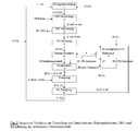
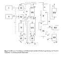
- the present invention accordingly provides a process for the preparation of diaryl carbonates starting from monophenols and carbonyl dihalide, which is characterized in that the resulting hydrogen halide by thermal oxidation with oxygen-containing gas by the Deacon process in the halogen and this in turn after isolation and reaction with Carbon monoxide is converted to carbonyl dihalide, which subsequently used again with the monophenol for the preparation of the diaryl carbonate.
- the monophenol which is released in the preparation of solvent-free polycarbonate by transesterification of diaryl carbonates and bisphenols can in turn be used to prepare the diaryl carbonate.
- the application relates to a method in which the prepared diaryl carbonate is used for the production of polycarbonate.
- step (c) At least a portion of the diaryl carbonate prepared according to step (c) is reacted with a bisphenol to give the oligo- / polycarbonate and the monophenol (the so-called transesterification reaction).
- the monophenol formed in the transesterification can be used in a further preferred embodiment again in step (b).
- the process according to the invention is a process for the preparation of diaryl carbonates and the thermal oxidation of hydrogen chloride with oxygen for the recovery of chlorine for the synthesis of phosgene as the starting material for diaryl carbonate preparation.
- the preparation of phosgene is carried out by reacting chlorine with carbon monoxide.
- the synthesis of phosgene is well known and is eg in Ullmann's Encyclopedia of Industrial Chemistry, 3rd Edition, Volume 13, pages 494-500 shown.
- phosgene is produced predominantly by reaction of carbon monoxide with chlorine, preferably on activated carbon as catalyst.
- the highly exothermic gas phase reaction takes place at temperatures of at least 250 ° C to a maximum of 600 ° C usually in tube bundle reactors.
- the removal of the heat of reaction can be done in different ways carried out, for example, by a liquid heat exchange medium, such as in WO 03/072237 described or by Siedekühlung via a secondary cooling circuit with simultaneous use of the heat of reaction for steam generation, such as in US 4,764,308 disclosed.
- step (a) From the phosgene formed according to step (a) at least one diaryl carbonate is formed by reaction with at least one monophenol in a next process step (b).
- Process step (b) is also referred to below as phosgenation. The reaction takes place with formation of hydrogen chloride as by-product.
- diaryl carbonates are also well known in the art, usually the monophenol is used in a stoichiometric excess, based on the phosgene.
- the phosgenation according to (b) takes place in the liquid phase, wherein the phosgene and the monophenol may be dissolved in the melt, optionally in a solvent.
- Preferred solvents are chlorinated aromatic hydrocarbons such as chlorobenzene, o-dichlorobenzene, p-dichlorobenzene, trichlorobenzenes, the corresponding chlorotoluenes or chloroxylenes, toluene, xylenes and the monophenol itself.
- the molten monophenol is a solvent.
- the phosgenation takes place in the gas phase.
- the gas phase phosgenation is eg in US 5,831,111 described.
- Suitable monophenols for the process according to the invention are phenols of the formula (I) wherein R is hydrogen, halogen or a branched or unbranched C 1 - to C 9 -alkyl radical, C 1 - to C 9 -alkoxy radical or C 1 - to C 9 -alkoxycarbonyl radical.
- Heterogeneous as well as homogeneous catalysts can be used for the process according to the invention.
- activated carbons ( EP 483 632 ), Aluminum oxides ( EP 635 477 ), Aluminosilicates ( EP 635 476 ), Metal oxides ( EP 645,364 ), Metallates ( EP 691,326 ), Hard materials ( EP 722 930 ) and mixed hydroxides ( DE 10 2008 050 828 ) both in the liquid phase ( EP 757 029 . EP 791 574 ) as well as in the gas phase ( EP 808 821 ) are used.
- metal salts their alkylates or organophosphorus compounds can be used.
- One or more activated or non-activated catalysts can be used.
- the homogeneous catalysts can be applied to an inert support, as in JP 695219 .
- WO 91/06526 US 5,424,473 and EP 516 355 described.
- the catalyst is added in amounts of from 0.5 to 100% by weight, based on the amount of monohydroxy compound (monophenol), in non-continuous operation or with charges of from 0.1 to 20 g of monohydroxy compound (monophenol) per g of catalyst per hour fully continuous driving, used.
- Phosgene can be used in process step (b) liquid, gaseous or optionally dissolved in an inert solvent.
- step (b) optionally usable inert organic solvents are, for example, toluene, chlorobenzene, dichlorobenzene and chlorotoluene, phenol itself is preferred.
- the reaction takes place above the boiling point of the phenol, preferably within a mean contact time of 0.5 to 5 seconds and at temperatures of 180 to 500 ° C.
- phosgenation in the liquid phase usually temperatures of 20 to 240 ° C and pressures of 1 to about 50 bar are used.
- the phosgenation in the liquid phase can be carried out in one or more stages, wherein in general phenol can be used in stoichiometric excess.
- the phenol and the phosgene can be combined via a static mixing element, in countercurrent or direct current, for example, via a fixed bed (heterogeneous) or in one or more reactive distillation columns or bubble columns (homogeneous) are performed, where the mixture reacts to the desired diaryl carbonate and hydrogen chloride.
- a static mixing element in countercurrent or direct current, for example, via a fixed bed (heterogeneous) or in one or more reactive distillation columns or bubble columns (homogeneous) are performed, where the mixture reacts to the desired diaryl carbonate and hydrogen chloride.
- reaction towers which are provided with suitable mixing elements
- reaction vessels with stirring device can also be used.
- special dynamic mixing elements can also be used. Suitable static and dynamic mixing elements are known in the art.
- step (c) the separation of the diaryl carbonates formed in the phosgenation takes place according to the invention in step (c).
- step (c) This is achieved by first separating the reaction mixture of the phosgenation into a liquid and a gaseous product stream in a manner known to the person skilled in the art.
- the liquid product stream essentially contains the diaryl carbonate, optionally the solvent and a small amount of unreacted phosgene.
- the gaseous product stream consists essentially of hydrogen chloride gas, unreacted phosgene, and minor amounts of optionally solvent and inert gases, such as nitrogen and carbon monoxide.
- step (c) the liquid stream according to step (c) is then subjected to a work-up, preferably a work-up by distillation, in which phosgene and optionally the solvent are removed successively.
- a further work-up of the diaryl carbonates formed is also carried out. This is done, for example, by purifying the resulting diaryl carbonate in a manner known to those skilled in the art by distillation or crystallization.
- the purification of the hydrogen chloride which may be necessary in step (d) may be due to the fact that the hydrogen chloride obtained in the reaction of phosgene with a phenol generally contains organic constituents which may interfere with the thermal oxidation of hydrogen chloride in step (e) that upon deactivation of the catalytically active material by contamination or damage, the catalyst must be replaced.
- organic constituents include, for example, phosgene, the monophenol or the solvents optionally used in the production of diaryl carbonate, such as chlorobenzene, o-dichlorobenzene or p-dichlorobenzene.
- step (d) the separation of the hydrogen chloride produced in the phosgenation according to step (b) from the gaseous product stream.
- the gaseous product stream obtained in the separation of the diphenyl carbonate according to step (c) is treated according to step (d) so that the phosgene is separated and the hydrogen chloride, optionally after purification, can be supplied to a thermal oxidation according to step (e) ,
- the separation of the hydrogen chloride in step (d) is carried out initially by phosgene is separated from the gaseous product stream.
- the separation of the phosgene is achieved by liquefaction of phosgene, for example on one or more capacitors connected in series.
- the liquefaction is preferably carried out at temperatures in the range of -15 to -40 °.
- parts of the organic impurities, such as e.g. Monophenol be removed from the gaseous product stream.
- the phosgene may be washed out of the gas stream in one or more stages with a cold solvent or solvent-phosgene mixture.
- Suitable solvents for this purpose are, for example, the solvents chlorobenzene and o-dichlorobenzene, which are optionally already used in the phosgenation.
- the temperature of the solvent or solvent-phosgene mixture for this is in the range of -15 to -46 ° C.
- the phosgene separated from the gaseous product stream can be recycled to the phosgenation according to step (b).
- step (d) a purification of the hydrogen chloride to reduce the proportion of organic impurities such as unreacted monophenol.
- This can be done, for example, by freezing, by passing the hydrogen chloride through, for example, one or more cold traps depending on the physical properties of the monophenol.
- step (d) cleaning of the hydrogen chloride two series-connected heat exchangers are flowed through by the hydrogen chloride stream, wherein the separated monophenol is frozen depending on the fixed point, for example, at -40 ° C.
- the heat exchangers are operated alternately, with the gas stream thawing out the previously frozen out monophenol in the first throughflowed heat exchanger.
- the monophenol can be used again for the preparation of the diaryl carbonate.
- the downstream second heat exchanger with a conventional heat transfer medium for refrigerators, e.g. a compound from the series of Friges, is applied, the gas is cooled below the fixed point of the monophenol, so that crystallized out.
- the hydrogen chloride-containing gas stream can be depleted in this way to preferably not more than 500 ppm, particularly preferably not more than 50 ppm, very particularly preferably not more than 20 ppm monophenol content.
- the purification of the hydrogen chloride in two series-connected heat exchangers according to US Pat. No. 6,719,957 respectively.
- the hydrogen chloride to a pressure of 5 to 20 bar, preferably 10 to 15 bar, compressed and the compressed gaseous hydrogen chloride at a temperature of 20 to 60 ° C, preferably 30 to 50 ° C, fed to a first heat exchanger.
- the hydrogen chloride with a cold hydrogen chloride at a temperature of -10 to -30 ° C, which comes from a second heat exchanger, cooled.
- This condense organic components that can be supplied to a disposal or recycling.
- the hydrogen chloride passed into the first heat exchanger leaves the latter at a temperature of -20 to 0 ° C.
- the condensate draining from the second heat exchanger is fed to a separation and evaporator unit.
- This may be, for example, a distillation column in which the hydrogen chloride is expelled from the condensate and returned to the second heat exchanger. It is also possible to return the expelled hydrogen chloride in the first heat exchanger.
- the cooled in the second heat exchanger and freed of organic hydrogen chloride is passed at a temperature of -10 to -30 ° C in the first heat exchanger. After heating to 10 to 30 ° C, the liberated from organic components hydrogen chloride leaves the first heat exchanger.
- step (d) cleaning of the hydrogen chloride by adsorption of organic impurities, such as monophenol, carried on activated carbon.
- organic impurities such as monophenol
- the hydrogen chloride is passed after removal of excess phosgene at a pressure of 0 to 5 bar, preferably from 0.2 and 2 bar, over or through an activated carbon bed.
- the flow rates and residence times are adjusted in a manner known to those skilled in the content of impurities.
- the adsorption of organic contaminants is also possible on other suitable adsorbents, e.g. on zeolites.
- a distillation of the hydrogen chloride may be provided for the optionally provided according to step (d) purification of the hydrogen chloride. This takes place after condensation of the gaseous hydrogen chloride.
- the purified hydrogen chloride is taken off as the top product of the distillation, the distillation being carried out under the conditions of pressure, temperature and the like which are known to the person skilled in the art and are customary for such a distillation. he follows.
- the hydrogen chloride is reacted with oxygen, if appropriate in the presence of a catalyst.
- the reaction can be carried out in the presence of catalysts at a temperature of about 250 to 450 ° C.
- the usual reaction pressure is in the range of 1 to 10 bar.
- Various embodiments of the process are described: Shell Chlorine Process, MT Chlorine Process, KEL Chlorine Process, Carrier Catalyst Process and Sumitomo Chlorine Process.
- Suitable catalysts for the Deacon process include transition metal compounds such as copper and ruthenium compounds or compounds of other noble metals such as gold and palladium. Such catalysts are for example in the writings DE 1 567 788 A1 . EP 251 731 A2 . EP 936 184 A2 . EP 761 593 A1 . EP 711 599 A1 and DE 102 50 131 A1 described.
- the catalysts are usually applied to a support. These carriers consist for example of silica, alumina, titania or zirconia.
- the Deacon processes are generally carried out in fluidized bed reactors or fixed bed reactors, for example in tube bundle reactors. Hydrogen chloride is freed of impurities before the reaction in order to avoid poisoning of the catalysts used.
- the reaction can be operated almost isothermally or almost adiabatically.
- the oxygen-containing gas is used in both the thermal and the non-thermal activated reaction of hydrogen chloride with oxygen usually as pure gas with an O 2 content of> 98% by volume. Lower levels of oxygen are also possible.
- the oxygen-containing gas may also contain, for example, nitrogen or carbon dioxide.
- the separated hydrochloric acid is preferably fed to a desorption stage in which gaseous hydrogen chloride is released again.
- This gaseous hydrogen chloride can be partially or preferably completely recycled to the reaction of hydrogen chloride with oxygen become.
- the dilute hydrochloric acid obtained in the desorption stage can be recycled to the hydrochloric acid condensation stage.
- the dilute hydrochloric acid serves as an absorbent for the gaseous hydrogen chloride to be separated off.
- the separated hydrochloric acid can also be supplied to another utilization.
- the chlorine-containing reaction gas mixture freed of residual water is then compressed in a preferred embodiment, whereby oxygen and other gas components remain in the gas phase and can be separated from the liquefied chlorine.
- oxygen and other gas components remain in the gas phase and can be separated from the liquefied chlorine.
- the chlorine produced according to step (e) is recycled to the production of phosgene according to step (a).
- the chlorine is preferably cooled in a one-stage or multi-stage cooling by means of a cooling unit, for example a tubular heat exchanger, and dried.
- the drying can take place, for example, with the aid of a suitable drying agent in an absorption column equipped with mass transfer elements.
- a suitable desiccant may be used, such as in DE 10 235 476 A be described, in addition to molecular sieves or hygroscopic adsorbents such as sulfuric acid.
- the drying can be done in one or more stages.
- the drying is preferably carried out in two stages by bringing the chlorine to be dried in a first stage with a sulfuric acid of lower concentration, preferably 70 to 80%, particularly preferably 75 to 80%, in contact.
- a sulfuric acid of lower concentration preferably 70 to 80%, particularly preferably 75 to 80%
- the residual moisture is removed from the chlorine by means of a more highly concentrated sulfuric acid of preferably 88 to 96%, more preferably 92-96%.
- the chlorine which has been dried in this way and has a residual moisture content of preferably not more than 100 ppm, more preferably not more than 20 ppm, can be passed through a droplet separator in order to remove any sulfuric acid droplets still contained therein.
- the hydrochloric acid After preparation of an aqueous hydrogen chloride solution according to step 1) and 2) and optionally after a purification of the aqueous hydrogen chloride solution, the hydrochloric acid is fed to an electrolysis cell.
- the electrochemical oxidation of the hydrochloric acid according to step 3) takes place according to the membrane process.
- so-called solid electrolyte systems such as Nafion ® membrane
- turned-sets include are, wherein the cathode is applied to one side of the ion exchange membrane.
- the cathode is eg a gas diffusion electrode.
- the catalytically active material of the cathode is in the Incorporated ion exchange membrane or may be applied to the ion exchange membrane.
- the electrochemical oxidation of an aqueous solution of hydrogen chloride using a gas diffusion electrode as a cathode is, for example, in WO 00/73538 and WO 02/18675 described.
- rhodium sulfide is used as the catalyst for the oxygen reduction at the cathode.
- This catalyst is largely resistant to organic constituents which may be present as impurities in the hydrochloric acid and derived for example from upstream synthesis steps.
- the organic components pass through the ion exchange membrane from the anode compartment into the cathode compartment.
- the electrochemical oxidation of the hydrochloric acid according to step (3) can be carried out by the membrane process in a two-compartment electrolysis cell, consisting of anode compartment and cathode compartment, or in a three-compartment electrolysis cell, consisting of anode compartment, cathode compartment and an electrolyte space between the anode and cathode compartment become.
- a two-compartment electrolysis cell is selected.
- the anode compartment is separated from the cathode compartment by an ion exchange membrane (hereinafter also referred to simply as a membrane), in particular a cation exchange membrane.
- the distance of the electrodes (anode and cathode) from the membrane is preferably 0 to 3 mm, particularly preferably 0 to 2 mm.
- Suitable ion exchange membranes are commercially available, such as single layer ion exchange membranes having sulfonic acid groups.
- DuPont type Nafion ® 117 can be used.
- electrodes containing graphite may be used, wherein the anode may be made of graphite.
- the electrochemical oxidation of the aqueous solution of hydrogen chloride according to step (3) takes place according to the membrane method with a gas diffusion electrode as an oxygen-consuming cathode.
- the electrolysis cell can consist of two chambers as well as of three chambers, but preferably of two chambers.
- the cathode half-cell is supplied with an oxygen-containing gas, for example oxygen, air or oxygen-enriched air. The oxygen is reduced at the gas diffusion electrode, forming water.
- the anode half-cell is fed to the aqueous hydrogen chloride solution, wherein the hydrogen chloride is oxidized at the anode to chlorine.
- the anode half cell and the cathode half cell are separated by a cation exchange membrane.
- the electrolysis of hydrochloric acid using a gas diffusion electrode as a cathode is, for example, in WO 00/73538 described.
- the electrolysis cell can be made of either a non-metallic material according to DE 103 47 703 A or consist of a metallic material.
- a metallic material for the electrolytic cell for example, titanium or a titanium alloy, such as a titanium-palladium alloy is suitable.
- the half shells for the anode and cathode half cell, the power distributor and the power supply lines are made of titanium or a titanium alloy.
- the anode can eg according to DE 102 34 806 A be executed.
- the anode consists of metal, preferably of titanium with a coating of noble metal oxide, for example of ruthenium oxide.
- the anode of titanium according to DE 102 00 072 A an intermediate layer of titanium carbide or titanium boride, which is applied by plasma or flame spraying on the titanium anode before the coating is applied from a noble metal oxide.
- the metal anode has openings for the passage of the gas formed during the electrolysis, the openings preferably having conductive structures which divert the gas formed to the side of the metal anode remote from the ion exchange membrane.
- the total cross-sectional area of the openings should be in the range of 20% to 70% of the area which is formed by the height and width of the anode.
- the metal anode may also have a wavy, zigzag or rectangular cross-section.
- the depth of the anode should be at least 1 mm.
- the ratio of electrochemically active area of the metal anode to the area formed by the height and width of the metal electrode should be at least 1.2.
- the metal anode can consist of two adjoining expanded metals, wherein the expanded metal facing the ion exchange membrane is more finely structured than the expanded metal repelling the ion exchange membrane.
- the finely structured expanded metal is rolled flat and the coarser textured expanded metal arranged so that the mesh webs are inclined in the direction of the cathode and serve as conductive structures.
- the anode may also consist of an expanded metal. Basically, the anode should have a free area of 15 to 70%.
- the thickness of the expanded metals should be chosen so that no additional electrical resistance occurs in a bipolar connection of the individual electrolysis cells (cell elements) to an electrolyzer. The electrical resistance depends essentially on the electrical contacting of the anode, such as, for example, the number of current-supplying connecting elements between the anode and the rear wall of the anode half-cell.
- the anode space and the cathode space can be separated from a commercially available ion exchange membrane.
- ion exchange membranes of the company. DuPont type Nafion ® 324 or Nafion ® can be used 117th
- a membrane is used which, as in WO 05/12596 described on the side facing the gas diffusion electrode side has a smooth surface structure. The smooth surface structure The membrane allows the gas diffusion electrode and the membrane abut each other such that under a pressure of 250 g / cm 2 and a temperature of 60 ° C, the contact area is at least 50% of the geometric area of the membrane.
- the cathodic current distributor to which the gas diffusion electrode is applied is preferably according to DE 102 03 689 A executed. This has a free area of less than 65%, but more than 5%.
- the thickness of the power distributor is at least 0.3 mm. It can consist of an expanded metal, mesh, fabric, foam, fleece, slotted sheet or perforated metal plate.
- the cathodic current distributor consists of an expanded metal with a mesh length of 4 to 8 mm, a mesh width of 3 to 5 mm, a ridge width of 0.4 to 1.8 mm and a thickness of 0.4 to 2 mm.
- the cathodic current distributor may comprise a second expanded metal as a carrier for the first expanded metal.
- the second expanded metal as a carrier preferably has a mesh length of 10 to 40 mm, a mesh width of 5 to 15 mm, a ridge width of 2 to 5 mm and a thickness of 0.8 to 4 mm.
- a network can be used, which preferably has a wire thickness of 1 to 4 mm and a mesh size of 7 to 25 mm.
- a perforated plate or slot plate can be used, which preferably has an open area of less than 60% and a thickness of 1 to 4 mm.
- a material for the cathodic power distributor for example, titanium or a noble metal-containing titanium alloy, such as titanium palladium can be used. If the power distributor is an expanded metal, then this is preferably rolled.
- a commercially available gas diffusion electrode can be used, which is equipped with a suitable catalyst.
- rhodium and / or rhodium oxide or mixtures thereof can be used.
- the gas diffusion electrode is preferably made of an electrically conductive fabric, paper or fleece made of carbon, wherein the fabric, paper or nonwoven on one side with a carbon-containing catalyst layer and on the other side is provided with a gas diffusion layer.
- the catalyst is preferably applied to a support, preferably of carbon, with integrated polytetrafluoroethylene particles which are coupled to the support structure.
- the gas diffusion layer is preferably made of carbon and polytetrafluoroethylene particles in which, for example, the ratio of carbon to PTFE is 50:50.
- the gas diffusion electrode may be arranged so that it is not firmly bonded to the ion exchange membrane.
- the contacting of the gas diffusion electrode with the current distributor and the ion exchange membrane is preferably carried out by press contact, ie the gas diffusion electrode, the power distributor and the membrane are pressed together.
- the gas diffusion electrode can be connected to the current collector according to DE 101 48 600 A be connected.
- the electrolysis of hydrochloric acid according to the membrane method with gas diffusion electrode is usually carried out at a temperature of 40 to 70 ° C.
- the concentration of the aqueous solution of hydrogen chloride in the anode compartment is 10 to 20 wt.%, Preferably 12 to 17 wt.%.
- the cell can be operated, for example, so that the pressure in the anode compartment is higher than the pressure in the cathode compartment.
- the cation exchange membrane is pressed onto the gas diffusion electrode and this in turn onto the current distributor.
- a construction of the electrolytic cell can be selected that in DE 101 38 214 A is described.
- the anode and / or the power distributor are elastically mounted, for example by being connected by springs to the rear wall of the respective half-cell.
- the elastic storage causes the pressing together of anode, membrane, gas diffusion electrode and power distributor.
- the electrolysis process is when starting the electrolytic cell according to DE 10 152 275 A
- the anode half-element is filled with a 5 to 20% strength by weight hydrochloric acid, the hydrochloric acid containing at least 10 ppm of free chlorine and the concentration of the hydrochloric acid during startup being more than 5% by weight.
- the volume flow of the hydrochloric acid through the anode compartment is adjusted so that at the beginning of the electrolysis, the hydrochloric acid flows at a rate in the anode space of 0.05 to 0.15 cm / s.
- the electrolysis is started at a current density of 0.5 to 2 kA / m 2 and increased at intervals of 5 to 25 minutes by 0.5 to 1.5 kA / m 2 .
- a predetermined current density of preferably 4 to 7 kA / m 2 is reached, the volume flow of hydrochloric acid is adjusted so that the hydrochloric acid flows in the anode half-element at a rate of 0.2 to 0.4 cm / s.
- a particularly advantageous mode of operation of the electrolysis cell can according to DE 101 38 215 A take place, after which the electrolysis cell is operated to lower the cell voltage with an increased pressure in the cathode chamber.
- the differential pressure between the anode compartment and the cathode compartment should be 0.01 to 1000 mbar and the oxygen pressure in the cathode compartment should be at least 1.05 bar absolute.
- the circulation procedure of the method according to the invention requires, in addition to the chlorine produced according to step (e) by thermal oxidation for the phosgene preparation according to step (a) to provide a further subset of chlorine, since losses of chlorine and hydrogen chloride in the Chlorine-hydrogen chloride cycle occur.
- the provision of another subset of chlorine may be in the form of elemental chlorine from an external source, such as the electrolysis of an aqueous solution of sodium chloride or hydrochloric acid.
- the occurring losses of chlorine and hydrogen chloride can also be compensated for by providing a partial amount of hydrogen chloride from an external source, for example from an isocyanate production plant (eg MDI, TDI), in which hydrogen chloride is obtained as a gaseous by-product.
- an isocyanate production plant eg MDI, TDI
- a partial amount of hydrogen chloride in the form of an aqueous solution of hydrogen chloride from an external source is preferably fed to electrolysis as ca 30% strength by weight hydrochloric acid.
- a hydrochloric acid of lower concentration may alternatively be added to the absorption of hydrogen chloride.
- the phosgene can be reused in the preparation of the diaryl carbonate according to step (b).
- step (b) The transesterification of the diaryl carbonate prepared according to step (b) with at least one bisphenol gives an oligo- / polycarbonate and monophenol, which in turn can be used in step (b).
- Suitable bisphenols for the process according to the invention are dihydroxydiarylalkanes of the formula (II) HO-Z-OH (II) wherein Z is a divalent organic radical of 6 to 30 carbon atoms containing one or more aromatic groups.
- dihydroxydiarylalkanes such as hydroquinone, re-sorcinol, dihydroxydiphenyl, bis (hydroxyphenyl) alkanes, bis (hydroxyphenyl) cycloalkanes, bis (hydroxyphenyl) sulfides, bis (hydroxyphenyl ) ethers, bis (hydroxyphenyl) ketones, bis (hydroxyphenyl) sulfones, bis (hydroxyphenyl) sulfoxides, ⁇ , ⁇ '-bis (hydroxyphenyl) diisopropylbenzenes, as well as their alkylated, nuclear alkylated and nuclear halogenated compounds ,
- dihydroxydiarylalkanes such as hydroquinone, re-sorcinol, dihydroxydiphenyl, bis (hydroxyphenyl) alkanes, bis (hydroxyphenyl) cycloalkanes, bis (hydroxyphenyl) sulfides, bis (hydroxyphenyl ) ethers
- Preferred bisphenols are 4,4'-dihydroxydiphenyl, 2,2-bis (4-hydroxyphenyl) -1-phenylpropane, 1,1-bis (4-hydroxyphenyl) phenylethane, 2,2-bis (4-hydroxyphenyl ) -propane (bisphenol A (BPA)), 2,4-bis (4-hydroxyphenyl) -2-methylbutane, 1,3-bis [2- (4-hydroxyphenyl) -2-propyl] -benzene (bisphenol M), 2,2-bis (3-methyl-4-hydroxyphenyl) propane, bis (3,5-dimethyl-4-hydroxyphenyl) methane, 2,2-bis (3,5-dimethyl) 4-hydroxyphenyl) -propane, bis (3,5-dimethyl-4-hydroxyphenyl) sulfone, 2,4-bis (3,5-dimethyl-4-hydroxyphenyl) -2-methylbutane, 1,3-bis - [2- (3,5-dimethyl-4-hydroxypheny
- bisphenols are 4,4'-dihydroxydiphenyl, 1,1-bis (4-hydroxyphenyl) phenylethane, 2,2-bis (4-hydroxyphenyl) propane (bisphenol A (BPA)), 2,2-bis (4-hydroxyphenyl) propane.
- BPA bisphenol A
- Bisphenol TMC bisphenol TMC
- Suitable bisphenols are for example in the US Pat. No. 2,999,835 . US 3 148 172 A . US 2 991 273 A . US 3 271 367 A . US 4 982 014 A and US 2,999,846 A in the German Offenlegungsschriften DE 15 70 703 A . DE 20 63 050 A . DE 20 36 052 A . DE 22 11 956 A and DE 38 32 396 A , the French patent FR 1 561 518 A in the monograph by H. Schnell, Chemistry and Physics of Polycarbonates, Interscience Publishers, New York 1964, p. 28ff; S.102ff and by DG Legrand, JT Bendler, Handbook of Polycarbonates Science and Technology, Marcel Dekker New York 2000, pp. 72ff , described.
- the polycarbonates can be deliberately and controllably modified by the use of small amounts of chain terminators and branching agents.
- Suitable chain terminators and branching agents are known from the literature. Some are for example in the DE-A 38 33 953 described.
- Preferably used chain terminators are phenol or alkylphenols, especially phenol, p-tert.butylphenol, iso-octylphenol, cumylphenol, their chlorocarbonic acid esters or acid chlorides of monocarboxylic acids or mixtures of these chain terminators.
- Preferred chain terminators are phenol, cumyl-phenol, isooctylphenol and para-tert-butylphenol.
- branching compounds are aromatic or aliphatic compounds having more than three, preferably three or four hydroxy groups.
- Particularly suitable examples with three or more than three phenolic hydroxyl groups are phloroglucinol, 4,6-dimethyl-2,4,6-tri- (4-hydroxyphenyl) -heptene-2, 4,6-dimethyl-2,4,6- tri- (4-hydroxyphenyl) heptane, 1,3,5-tri (4-hydroxyphenyl) benzene, 1,1,1-tris (4-hydroxyphenyl) ethane, tri (4-hydroxyphenyl) phenylmethane, 2,2-bis (4,4-bis (4-hydroxyphenyl) cyclohexyl] propane, 2,4-bis (4-hydroxyphenyl-isopropyl) -phenol and tetra (4-hydroxyphenyl) -methane.
- trifunctional compounds suitable as branching agents are 2,4-dihydroxybenzoic acid, trimesic acid, cyanuric chloride and 3,3-bis (3-methyl-4-hydroxyphenyl) -2-oxo-2,3-dihydroindole.
- Particularly preferred branching agents are 3,3-bis (3-methyl-4-hydroxyphenyl) -2-oxo-2,3-dihydroindole and 1,1,1-tri- (4-hydroxyphenyl) -ethane.
- the optionally used 0.05 to 2 mol%, based on bisphenols, of branching agents can be used together with the bisphenols.
- the reaction components for the first step, the transesterification, ie, the bisphenols and the diaryl carbonates, are free of alkali and alkaline earth ions, with amounts of less than 0.1 ppm of alkali metal and alkaline earth metal ions being tolerable.
- Such pure bisphenols or diaryl carbonates are obtainable by recrystallizing, washing or distilling the bisphenols or diaryl carbonates.
- the content of alkali metal and alkaline earth metal ions in both the bisphenol and the diaryl carbonates should be ⁇ 0.1 ppm.
- the transesterification reaction of the bisphenol and the diaryl carbonate in the melt is preferably carried out in two stages.
- the melting of the bisphenol and the diaryl carbonate takes place at temperatures of 80-250 ° C., preferably 100-230 ° C., more preferably 120 -190 ° C. under normal pressure in 0-5 hours, preferably 0.25-3 Hours instead.
- the catalyst After addition of the catalyst by applying vacuum (up to 2 mm Hg) and increasing the temperature (up to 260 ° C) by distilling off the monophenol, the oligocarbonate from the bisphenol and the diaryl carbonate is prepared.
- the oligocarbonate thus prepared has a weight average molecular weight M w (determined by measuring the relative solution viscosity in dichloromethane or in mixtures of equal amounts by weight of phenol / o-dichlorobenzene, calibrated by light scattering) in the range from 2000 to 18,000, preferably from 4,000 to 15 000.
- M w weight average molecular weight
- the polycarbonate In the second stage, in the polycondensation by further increasing the temperature to 250 - 320 ° C, preferably 270 - 295 ° C and a pressure of ⁇ 2 mm Hg produced the polycarbonate. In this case, the remainder of monophenols is recovered. There may be low losses of monophenols ⁇ 5%, preferably ⁇ 2%, particularly preferably ⁇ 1%, caused by End groups in the polycarbonate and residual monophenol in the polycarbonate. These losses must be compensated by appropriate amounts of monophenol for the preparation of the diaryl carbonate.
- Catalysts in the context of the process according to the invention for the transesterification of the bisphenol and of the diaryl carbonate to the polycarbonate are all inorganic or organic basic compounds, for example lithium, sodium, potassium, cesium, calcium, barium, magnesium, hydroxides, carbonates , halides, phenolates, diphenolates, fluorides, acetates, phosphates, - hydrogen phosphates, boronates, nitrogen and phosphorbases such as tetramethylammonium hydroxide, tetramethylammonium acetate, tetramethylammonium fluoride, tetramethylammonium tetraphenylboranate, tetraphenylphosphonium fluoride, tetraphenylphosphonium tetraphenylboranate, dimethyldiphenylammonium hydroxide, tetraethylammonium hydroxide, DBU, DBN or guanidine systems such as 1,5
- These catalysts are used in amounts of 10 -2 to 10 -8 mol, based on 1 mol of bisphenol.
- the catalysts can also be used in combination (two or more) with each other.
- alkali / alkaline earth metal catalysts When using alkali / alkaline earth metal catalysts, it may be advantageous to add the alkali / alkaline earth metal catalysts at a later time (e.g., after the oligocarbonate synthesis in the second stage polycondensation).
- the addition of the alkali / alkaline earth metal catalyst may e.g. as a solid or as a solution in water, phenol, oligocarbonate or polycarbonate.
- the reaction of the bisphenol and of the diaryl carbonate to form the polycarbonate can be carried out batchwise or preferably continuously in the context of the process according to the invention
- stirred tanks thin film evaporators, falling film evaporators, stirred tank cascades, extruders, kneaders, simple disk reactors and high-viscosity disk reactors.
- the aromatic polycarbonates of the process according to the invention should have average weight molecular weights M w of from 18,000 to 80,000, preferably from 19,000 to 50,000, determined by measuring the rel. Solution viscosity in dichloromethane or in mixtures of equal amounts by weight of phenol / o-dichlorobenzene, calibrated by light scattering.
- the crude monophenols which are isolated during the transesterification process may, depending on the transesterification conditions and distillation conditions, inter alia. with diaryl carbonates, the bisphenol, salicylic acid, isopropenylphenol, Phenoxybenzoeklarephenylester, xanthone, the Hydroxymonoarylcarbonat be contaminated.
- the cleaning can be carried out according to the usual cleaning procedure, ie z. B. distillation or recrystallization.
- the purity of the monophenols is then> 99%, preferably> 99.8%, particularly preferably> 99.95%.
- diaryl carbonates and polycarbonates in combination with the thermal oxidation of hydrogen chloride also offers the possibility of drawing concentrated hydrochloric acid of about 30% from hydrogen chloride, if necessary, to remove concentrated hydrochloric acid for other applications.
- concentrated hydrochloric acid is in the food industry.
- the concentrated hydrochloric acid prepared by the process according to the invention e.g. by absorptive purification on an activated carbon bed, as known from the prior art, a sufficiently high purity for the food industry can be achieved.
- the process according to the invention for the preparation of diaryl carbonates and polycarbonates can optionally be combined with other possible uses of the hydrogen chloride obtained in the production of diaryl carbonate, such as, for example, B. the use as starting material for the Ethylenendichloridher ein be combined in the PVC production.
- the examples are intended to illustrate the process according to the invention on the basis of the thermal oxidation of the hydrogen chloride obtained in the preparation of diphenyl carbonate to chlorine, the conversion of which into phosgene which can be reused in the diphenyl carbonate preparation process (DPC process) ( FIG. 2 ), with recycling of the phenol formed in the production of polycarbonate in the preparation of diphenyl carbonate ( FIG. 1 ).
- a first stage 1 of diaryl carbonate production Chlorine 11 is reacted with carbon monoxide 10 to phosgene 13.
- Step 2 phosgene 13 from Step 1 is reacted with a monophenol 14 (eg, phenol) to give a mixture of diaryl carbonate (eg, diphenyl carbonate, DPC) and hydrogen chloride, which in Step 3 is converted into diaryl carbonate 16 which is recycled and HC1.
- Gas 17, which is subjected to a cleaning 4 is separated.
- the purified HC1 gas 18 is reacted with oxygen in the HC1 oxidation process 5, here in a Deacon process by means of catalyst.
- reaction mixture 19 from stage 5 is cooled (stage 6).
- Unreacted hydrogen chloride 26, which is optionally mixed with water or dilute hydrochloric acid, is discharged and fed to an electrolysis 9.
- the resulting gas mixture 20 consisting at least of chlorine, oxygen and minor constituents such as nitrogen, carbon dioxide, etc. is treated with conc. Sulfuric acid 21 (96%) dried (step 7).
- a purification stage 8 chlorine 11 is separated from the gas mixture 22 from stage 7. Residual stream 23 containing oxygen and minor components is recycled to stage 5 (Deacon oxidation) and stage 9 (electrolysis).
- the electrolysis stage is an ODC electrolysis in which on the cathode side a gas diffusion electrode and oxygen is used as a reactant.
- the chlorine gas 11 obtained from the purification stage 8 can be used again directly in the phosgene synthesis 1.
- the concentration of hydrochloric acid 27 fed to the electrolytic cell 9 is 14 to 15% by weight of HCl, and the hydrochloric acid 28 leaving the electrolytic cell 9 is 11 to 13% by weight of HCl.
- the hydrochloric acid stream 28 is mixed with concentrated hydrochloric acid 26 from the separation stage 6 and fed again to the electrolytic cell 9.
- the oxygen consumed at stages 5 and 9 is replaced by oxygen from an external source 24.
- the oxygen 25 not consumed in the cathode compartment of the electrolysis cell is circulated and mixed with fresh oxygen from an external source 24.
- the chlorine 30 produced in accordance with step 9 is combined with the chlorine-containing gas stream 20 and the combined gas stream is cooled in one or more stages by means of a cooling unit, e.g. a tube heat exchanger, cooled and dried.
- a cooling unit e.g. a tube heat exchanger
- Drying 7 can be carried out, for example, with the aid of a suitable drying agent in an absorption column equipped with mass transfer elements.
- a suitable desiccant may be used, such as in DE 10 235 476 A be described, in addition to molecular sieves or hygroscopic adsorbents such as sulfuric acid.
- the drying can be done in one or more stages. Drying is preferably carried out in two stages by contacting the chlorine to be dried in a first stage with a sulfuric acid of a lower concentration, preferably from 70 to 80%, particularly preferably from 75 to 80%. In a second stage, the residual moisture is removed from the chlorine by means of a more highly concentrated sulfuric acid of preferably 88 to 96%, more preferably 92-96%.
- the chlorine 22 dried in this way and having a residual moisture content of preferably not more than 100 ppm, particularly preferably not more than 20 ppm, can be passed through a droplet separator in order to remove any sulfuric acid droplets still contained therein.
- the dried chlorine gas stream 22 is then subjected to chlorine purification 8.
- the very pure chlorine 11 is supplemented with chlorine from an external source 12 and fed back to the production of phosgene 1.
- FIG. 3 The apparatus used for carrying out the process according to the invention and the material streams occurring are shown schematically in FIG. 3 played.
- the phenyl chloroformate present in the sump 7 is converted into diphenyl carbonate at 180 ° C. by subsequent reaction with phenol present (possibly after the addition of additional phenol (1 'or 14') in a postreactor VIII, likewise filled with ⁇ -aluminum oxide (150 parts by volume) implemented.
- the product 8 taken off at the reactor base (weight ratio phenol, diphenyl carbonate and by-products 55.4 / 44.3 / 0.3) is removed via degasifier IX in offgas 9 (phenol / hydrogen chloride) and bottom 10 (weight ratio phenol, diphenyl carbonate and by-products 55.2 / 44.5 / 0.3).
- Bottom 10 is fed into a first distillation column X and separated at about 80 ° C / 16 mbar (12 mm) in 57.7 parts by weight / h phenol and bottom 19 (weight ratio phenol, diphenyl carbonate and by-products 0.3 / 99.1 / 0.6).
- Bottom 19 is fed to a second distillation column XI, in which overhead phenol (0.14 parts by weight) is removed and returned to the upper part of the first column X.
- the product taken from the bottom 22 (weight ratio diphenyl carbonate / by-products 88.6 / 11.4) is in a third distillation column XII at 170 ° C / 12mm in overhead product 21 (2.3 parts by weight / h diphenyl carbonate), which in the the lower part of the second column XI is recycled, and bottoms 23 (high-boiling by-products) separated.
- a third distillation column XII at 170 ° C / 12mm in overhead product 21 (2.3 parts by weight / h diphenyl carbonate), which in the lower part of the second column XI is recycled, and bottoms 23 (high-boiling by-products) separated.
- By lateral outfeed from the gas space of the 2nd column XI is obtained 46.6 parts by weight / h of product 20 (weight ratio of diphenyl carbonate, phenol 99.8 / 0.2), the product container XIII is supplied.
- Waste gas streams 6 and 9 are combined to 15 (weight ratio phenol, hydrogen chloride and carbon dioxide 5.8 / 93.6 / 0.6) and passed through phenol in the countercurrent apparatus VII.
- the exiting at the head exhaust 15 ' is fed to a cleaning system XIV, where the hydrogen chloride gas is released by freezing of phenol.
- the product leaving the foot containing phenyl chloroformate and diphenyl carbonate in a weight ratio of 3 to 97, (phenol conversion 69.5%, selectivity 99.6%) is isolated after reacting the existing phenyl chloroformate with phenol to give diphenyl carbonate in a residence time reactor and by degassing into the exhaust gas and the bottom separated.
- the exiting at the top of the reactive distillation plant exhaust gas stream is combined with the exhaust gas from the degassing and freed of small amounts of phosgene and phenol by freezing.
- the phosgene conversion was measured by determining the phosgene content in a built-in exhaust gas gas mouse by reaction with excess ethanol and correlation of the formed ethyl chloroformate and diethyl carbonate with the amount of unreacted phosgene.
- the product leaving the foot containing phenol, phenyl chloroformate, diphenyl carbonate and by-products (weight ratio 31.7 / 5.2 / 62.8 / 0.3) (phosgene conversion 83.5%, phenol conversion 64.8%, selectivity 99.7% ) is isolated by reacting the existing phenyl chloroformate with phenol to diphenyl carbonate in a residence time and separated by degassing in the exhaust gas and bottom (weight ratio of phenol, diphenyl carbonate and by-products 29.2 / 70.4 / 0.4).
- the exiting at the top of the reactive distillation plant exhaust gas stream is combined with the exhaust gas from the degassing and freed of small amounts of phosgene and phenol by freezing.
- the product emerging at the foot containing phenol, phenyl chloroformate, diphenyl carbonate and by-products (weight ratio 60.7 / 3.5 / 34.8 / 0.6) (phosgene conversion 71.6%, phenol conversion 35.4%, selectivity 99%) is isolated by reaction of the existing chloroformate with phenol to diphenyl carbonate in a residence time reactor and separated by degassing in the exhaust gas and bottom (weight ratio phenol, diphenyl carbonate and by-products 59.6 / 39.6 / 0.8).
- the waste gas is combined with the exhaust gas stream emerging at the top of the reactive distillation plant and freed from small amounts of phosgene and phenol by freezing.
- the reaction mixture of the first bubble column containing phenyl chloroformate and diphenyl carbonate in a weight ratio of 2 to 98 is isolated by reacting the existing phenyl chloroformate with phenol to diphenyl carbonate in a residence time and by degassing in exhaust gas and Sludge separated, which is separated by distillation.
- the exhaust gas stream emerging at the top of the 1st bubble column is passed through a gas frit into the second bubble column.
- the phenol conversion in the 2nd bubble column is 22.0% after 3 hours.
- the reaction mixture in the 1st bubble column contains phenyl chloroformate and diphenyl carbonate in a weight ratio of 0.6 to 99.4 (phenol conversion 80.2%, selectivity 99, 5%). In the 2nd bubble column the phenol conversion is 12.3%.
- the reaction mixture in the 1st bubble column contains phenyl chloroformate and diphenyl carbonate in a weight ratio of 0.7 to 99.3 (phenol conversion 81, 5%, selectivity 99.4%). In the 2nd bubble column the phenol conversion is 17.4%.
- the product emerging at the foot containing phenyl chloroformate and diphenyl carbonate in a weight ratio of 0.6 to 99.4 (phosgene conversion 87%, phenol 59.8%, selectivity 99.9%) is isolated after reacting the existing phenyl chloroformate with phenol to diphenyl carbonate in a residence time reactor and separated by degassing in the exhaust and sump.
- the resulting in the continuous production of diaryl carbonates by reaction of monophenols and phosgene in the presence of catalysts hydrogen chloride can after removal of the minor phosgene and Monophenolverungraphyen example. be supplied by freezing without extensive purification, optionally after treatment with activated carbon of an electrochemical oxidation.
- a stream of 35.9 parts by weight / h of purified hydrogen chloride from a Diarylcarbonather ein is divided into two streams. 29.5 parts by weight / h are fed to HC1 oxidation and 6.4 parts by weight / h to HC1 absorption. 29.5 parts by weight / h of HC1 are fed with 12.9 parts by weight / h of oxygen (content greater than 99%) of a catalytic HC1 oxidation. The oxidation takes place at 333 ° C and 3.4 bar. The HC1 conversion in the reactor is 85%. The gas leaving the reactor-gas mixture is cooled to 100 ° C, the condensed HC1 with the water of reaction in a HC1 absorption.
- the cooled process gas stream (weight ratio HC1, oxygen, chlorine and water 4.4 / 7.4 / 24.4 / 6.18) is passed with 6.4 parts by weight / h of purified hydrogen chloride in the HC1 absorption.
- HC1 absorption unit a 30% by weight hydrochloric acid 26 is prepared, which is combined with the remainder of the depleted anolyte acid 28 and returned to the electrolysis cell. 2.96 parts by weight / h of the depleted Anolyt Textre 28 are discharged from the Anolyte acid cycle.
- the electrolysis is operated at a current density of 5 kA / m 2 at 55 ° C and a voltage of 1.39 V.
- the anode and cathode material used is a palladium-stabilized titanium. At the ruthenium oxide-coated anode of DENORA, Germany, 10.1 parts by weight / h of chlorine is developed.
- Anode and cathode half-shell are separated by an ion exchange membrane from DUPONT, type Nafion 324.
- the cathode used is an oxygen-consuming cathode from ETEK, which contains a rhodium-sulfide-supported catalyst.
- Oxygen is supplied to the cathode half-element with 100% excess, ie, 9.17 parts by weight / h.
- the oxygen is recycled to the electrolysis, a purge stream of 1% of the feed amount is discharged behind the electrolysis 9 (not shown) or used in the HC1 oxidation 5.
- the pressure in the anode half cell is higher than that in the cathode half cell.
- the differential pressure is 200 mbar.
- the cathode half cell is taken from a condensate stream of 8.8 parts by weight / h.
- the electrolysis unit 9 consists of 615 electrolysis elements, wherein an element consists of an anode half-shell with anode, an ion exchange membrane and a cathode half-shell with oxygen-consuming cathode.
- the oxidation is carried out as described in 2a).
- a purified HC1 gas stream of 35.9 parts by weight / hr from a diaryl carbonate preparation is fed to the thermal HC1 oxidation with 100% excess oxygen, ie, 15.7 parts by weight / h of oxygen.
- the conversion is 85%, so that the reactor 5.4 parts by weight / h of HCl, 9.0 parts by weight / h of oxygen, 7.5 parts by weight / h of water and 29.7 parts by weight / h leave chlorine.
- This process gas 19 is fed to an HCl absorption, which is operated with a first partial flow of 177.8 parts by weight / h of a NaCl-depleted NaCl-containing solution (18.3% by weight NaCl) originating from NaCl electrolysis , In this NaCl-containing solution, the water and the hydrogen chloride of the process gas 19 is absorbed.
- the stream leaving the absorption is composed as follows: 152.8 parts by weight / h of water, 32.5 parts by weight / h of NaCl, 5.4 parts by weight / h of hydrogen chloride.
- NaC1 electrolysis consists of 1475 bipolar electrolysis elements per 2.71m 2 membrane area.
- NaC1 electrolysis is operated with titanium anode shells bearing a noble metal oxide coated titanium anode.
- the cathode half shell is made of nickel and carries a noble metal oxide coated nickel cathode.
- Anode and cathode half-shell are separated by an ion exchange membrane from DUPONT Nafion 982.
- the melt is then passed through an expansion valve in a below 200 mbar separator.
- the effluent melt is reheated to 189 ° C in a falling film evaporator, also below 200 mbar, and collected in a receiver. After a residence time of 20 minutes, the melt is pumped into the next three, similarly constructed stages.
- the conditions in the 2nd / 3rd / 4th stages are 100/74/40 mbar, 218/251/276 ° C and 20/10/10 minutes.
- the resulting oligomer has a relative viscosity of 1.09. All vapors are passed through pressure controls in a column under vacuum and discharged as condensates.
- the oligomer is condensed in a subsequent basket reactor at 278 ° C and 3.0 mbar at a residence time of 45 minutes to a higher molecular weight product.
- the relative viscosity is 1.195.
- the vapors are condensed.
- a partial flow of 150 parts by weight / h melt is branched off by means of a gear pump, mixed with 0.185 parts by weight / h of a 5% aqueous phosphoric acid, with a static mixer stirred at a length to diameter ratio of 20 and returned to the skin melt stream.
- the phosphoric acid is homogeneously distributed throughout the melt stream by means of another static mixer.
- the melt thus treated is further exposed in a further basket reactor at 284 ° C, 0.7 mbar and at an average residence time of 130 minutes the process conditions, discharged and granulated.
- the vapors are condensed in the vacuum system and behind it.
- the resulting polycarbonate has the following characteristics: relative viscosity 1.201 / phenolic OH 255 [ppm] / DPC 71 [ppm] / BPA 6 [ppm] / phenol 56 [ppm].
- the distilled phenol can be recycled back to the diphenyl carbonate preparation according to step (b) as described in Examples 1 a-h).
Priority Applications (1)
| Application Number | Priority Date | Filing Date | Title |
|---|---|---|---|
| EP11160021.9A EP2371807B1 (fr) | 2010-03-30 | 2011-03-28 | Procédé de fabrication de diarylcarbonates et de polycarbonates |
Applications Claiming Priority (2)
| Application Number | Priority Date | Filing Date | Title |
|---|---|---|---|
| EP10158446 | 2010-03-30 | ||
| EP11160021.9A EP2371807B1 (fr) | 2010-03-30 | 2011-03-28 | Procédé de fabrication de diarylcarbonates et de polycarbonates |
Publications (2)
| Publication Number | Publication Date |
|---|---|
| EP2371807A1 true EP2371807A1 (fr) | 2011-10-05 |
| EP2371807B1 EP2371807B1 (fr) | 2017-07-26 |
Family
ID=42668643
Family Applications (1)
| Application Number | Title | Priority Date | Filing Date |
|---|---|---|---|
| EP11160021.9A Not-in-force EP2371807B1 (fr) | 2010-03-30 | 2011-03-28 | Procédé de fabrication de diarylcarbonates et de polycarbonates |
Country Status (8)
| Country | Link |
|---|---|
| US (1) | US9175135B2 (fr) |
| EP (1) | EP2371807B1 (fr) |
| JP (2) | JP6122570B2 (fr) |
| KR (1) | KR101834011B1 (fr) |
| CN (1) | CN102206158B (fr) |
| ES (1) | ES2644525T3 (fr) |
| RU (1) | RU2011111758A (fr) |
| SG (1) | SG174715A1 (fr) |
Cited By (4)
| Publication number | Priority date | Publication date | Assignee | Title |
|---|---|---|---|---|
| EP2586767A1 (fr) | 2011-10-25 | 2013-05-01 | Bayer MaterialScience AG | Procédé de fabrication de diarylcarbonates et de polycarbonates |
| WO2013189861A1 (fr) | 2012-06-19 | 2013-12-27 | Akzo Nobel Chemicals International B.V. | Procédé pour la préparation de carbonates organiques cycliques |
| WO2015169775A1 (fr) | 2014-05-09 | 2015-11-12 | Covestro Deutschland Ag | Procédé de production de diarylcarbonates |
| EP4083106A1 (fr) * | 2021-04-30 | 2022-11-02 | Covestro Deutschland AG | Processus de production de polycarbonate à durabilité améliorée |
Families Citing this family (18)
| Publication number | Priority date | Publication date | Assignee | Title |
|---|---|---|---|---|
| SG174715A1 (en) * | 2010-03-30 | 2011-10-28 | Bayer Materialscience Ag | Process for preparing diaryl carbonates and polycarbonates |
| RU2014104305A (ru) * | 2011-07-08 | 2015-08-20 | Байер Интеллектуэль Проперти Гмбх | Способ получения диарилкарбонатов |
| EP2711353B1 (fr) | 2012-09-20 | 2018-10-31 | SABIC Global Technologies B.V. | Procédé pour la fabrication en continu de carbonate d'alkyle aryle et de carbonate de diaryle par recompression de vapeur |
| EP2935197B1 (fr) * | 2012-12-18 | 2017-07-12 | Covestro Deutschland AG | Procédé de fabrication de carbonates de diaryle |
| KR102078126B1 (ko) | 2013-07-26 | 2020-02-17 | 사빅 글로벌 테크놀러지스 비.브이. | 고순도 포스겐의 제조 방법 및 제조 장치 |
| KR102041556B1 (ko) * | 2013-07-26 | 2019-11-06 | 사빅 글로벌 테크놀러지스 비.브이. | 고순도 포스겐의 제조 방법 및 제조 장치 |
| CN103664628A (zh) * | 2013-12-12 | 2014-03-26 | 武汉工程大学 | 脂肪族氯代物间接光气法制备有机碳酸酯的方法 |
| US9670131B2 (en) | 2014-02-04 | 2017-06-06 | Sabic Global Technologies B.V. | Method for producing carbonates |
| KR101859207B1 (ko) | 2014-02-04 | 2018-05-18 | 사빅 글로벌 테크놀러지스 비.브이. | 카보네이트 제조 방법 |
| US9643163B2 (en) | 2014-10-10 | 2017-05-09 | Crystaphase Products, Inc. | Heterogeneous catalyst for transesterification and method of preparing same |
| WO2016168697A1 (fr) | 2015-04-17 | 2016-10-20 | Crystaphase Products, Inc. | Catalyseur hétérogène pour transestérification et son procédé de préparation |
| KR20200024871A (ko) * | 2017-07-03 | 2020-03-09 | 코베스트로 도이칠란트 아게 | 아릴알킬 카르보네이트 또는 디아릴 카르보네이트를 제조하기 위한 전기화학적 방법 |
| JP7199546B2 (ja) | 2019-08-22 | 2023-01-05 | 富士フイルム株式会社 | カルボニル化合物の製造方法、及びカルボニル化合物を製造するフロー式反応システム |
| WO2021033505A1 (fr) | 2019-08-22 | 2021-02-25 | 富士フイルム株式会社 | Procédé de production d'un composé carbonyle et système de réaction continue utilisé pour la production d'un composé carbonyle |
| EP3851478A1 (fr) * | 2020-01-17 | 2021-07-21 | Covestro Deutschland AG | Procédé de fabrication d'un polycarbonate à récupération améliorée des diarylcarbonate non réactif |
| CN111517922B (zh) * | 2020-04-28 | 2022-11-04 | 万华化学集团股份有限公司 | 一种制备4-氯-3,5-二甲基苯酚的方法 |
| BR112023026597A2 (pt) * | 2021-07-27 | 2024-03-05 | Albemarle Corp | Processo para purificar soluções de haleto de hidrogênio contendo impurezas orgânicas |
| CN114100323A (zh) * | 2021-11-15 | 2022-03-01 | 德沃德科技(重庆)有限责任公司 | 一种固体光气尾气分离工艺及设备 |
Citations (64)
| Publication number | Priority date | Publication date | Assignee | Title |
|---|---|---|---|---|
| US2362865A (en) | 1941-07-18 | 1944-11-14 | Gen Chemical Corp | Manufacturie of aromatic esters |
| US2837555A (en) | 1956-09-20 | 1958-06-03 | Dow Chemical Co | Preparation of carbonate esters |
| US2991273A (en) | 1956-07-07 | 1961-07-04 | Bayer Ag | Process for manufacture of vacuum moulded parts of high molecular weight thermoplastic polycarbonates |
| US2999846A (en) | 1956-11-30 | 1961-09-12 | Schnell Hermann | High molecular weight thermoplastic aromatic sulfoxy polycarbonates |
| US2999835A (en) | 1959-01-02 | 1961-09-12 | Gen Electric | Resinous mixture comprising organo-polysiloxane and polymer of a carbonate of a dihydric phenol, and products containing same |
| US3148172A (en) | 1956-07-19 | 1964-09-08 | Gen Electric | Polycarbonates of dihydroxyaryl ethers |
| US3234263A (en) | 1962-07-03 | 1966-02-08 | Union Carbide Corp | Process for preparing diaryl carbonates |
| US3271367A (en) | 1955-03-26 | 1966-09-06 | Bayer Ag | Thermoplastic polycarbonates of dihydroxydiarylene sulfones and their preparation |
| FR1561518A (fr) | 1967-03-10 | 1969-03-28 | ||
| DE1570703A1 (de) | 1964-10-07 | 1970-02-12 | Gen Electric | Hydrolytisch stabile Polycarbonate sowie Verfahren zu deren Herstellung |
| DE1567788A1 (de) | 1964-04-23 | 1970-05-27 | Shell Internationale Research Maatschappij N.V., Den Haag | Verfahren zur Herstellung von Chlor, Brom oder Jod |
| DE2036052A1 (en) | 1970-07-21 | 1972-01-27 | Milchwirtschafthche Forschungs und Untersuchungs Gesellschaft mbH, 2100 Hamburg | Working up of additives in fat and protein - contng foodstuffs |
| DD88309A1 (de) | 1971-05-12 | 1972-03-05 | Verfahren zur Herstellung von Chlor | |
| DE2063050A1 (de) | 1970-12-22 | 1972-07-13 | Bayer | Verseifungsbeständige Polycarbonate |
| DE2211956A1 (de) | 1972-03-11 | 1973-10-25 | Bayer Ag | Verfahren zur herstellung verseifungsstabiler blockcopolycarbonate |
| DE2447348A1 (de) | 1974-10-04 | 1976-04-15 | Bayer Ag | Verfahren zur herstellung von diarylcarbonaten |
| JPS5973405A (ja) | 1982-10-20 | 1984-04-25 | Mitsui Toatsu Chem Inc | 塩素の製造方法 |
| EP0251731A2 (fr) | 1986-06-30 | 1988-01-07 | MITSUI TOATSU CHEMICALS, Inc. | Procédé de production de chlore |
| US4764308A (en) | 1983-07-28 | 1988-08-16 | Bayer Aktiengesellschaft | Process for the production of phosgene with simultaneous generation of steam |
| DE3832396A1 (de) | 1988-08-12 | 1990-02-15 | Bayer Ag | Dihydroxydiphenylcycloalkane, ihre herstellung und ihre verwendung zur herstellung von hochmolekularen polycarbonaten |
| DE3833953A1 (de) | 1988-10-06 | 1990-04-19 | Bayer Ag | Mischungen von speziellen, neuen polycarbonaten mit anderen thermoplasten oder mit elastomeren |
| US4982014A (en) | 1988-08-12 | 1991-01-01 | Bayer Aktiengesellschaft | Dihydroxydiphenyl cycloalkanes, their production and their use for the production of high molecular weight polycarbonates |
| WO1991006526A1 (fr) | 1989-10-30 | 1991-05-16 | The Dow Chemical Company | Procede et catalyseur de production de carbonates de diaryle |
| EP0483632A2 (fr) | 1990-11-01 | 1992-05-06 | Bayer Ag | Procédé de préparation de carbonates d'aryle |
| US5136077A (en) | 1989-12-18 | 1992-08-04 | The Dow Chemical Company | Process for the preparation of diaryl carbonates |
| EP0516355A2 (fr) | 1991-05-28 | 1992-12-02 | The Dow Chemical Company | Trifluorure d'aluminium comme catalyseur pour produire des carbonates de diaryle |
| SU1801943A1 (ru) | 1991-03-19 | 1993-03-15 | Волгоградский Политехнический Институт | Способ получения хлора из хлористого водорода 2 |
| JPH0695219A (ja) | 1992-09-17 | 1994-04-08 | Olympus Optical Co Ltd | ストロボ装置 |
| US5340905A (en) | 1992-11-12 | 1994-08-23 | Bayer Aktiengesellschaft | Process for the preparation of thermoplastic polycarbonates |
| EP0635476A1 (fr) | 1993-07-19 | 1995-01-25 | Bayer Ag | Procédé de préparation carbonates d'aryle |
| EP0635477A1 (fr) | 1993-07-19 | 1995-01-25 | Bayer Ag | Procédé de préparation de carbonates d'aryle |
| EP0645364A1 (fr) | 1993-09-28 | 1995-03-29 | Bayer Ag | Procédé de préparation de carbonates d'aryle |
| LU88569A1 (de) | 1994-12-14 | 1995-04-05 | Bayer Ag | Verfahren zur Herstellung von thermoplastischem Polycarbonat |
| US5424473A (en) | 1994-03-16 | 1995-06-13 | The Dow Chemical Company | Process for the preparation of aryl haloformates and diaryl carbonates |
| EP0691326A1 (fr) | 1994-07-07 | 1996-01-10 | Bayer Ag | Procédé de préparation de carbonates d'aryle |
| EP0711599A1 (fr) | 1994-11-14 | 1996-05-15 | Mitsui Toatsu Chemicals, Incorporated | Catalyseur pour la préparation du chlore à partir de chlorure d'hydrogène |
| EP0722930A1 (fr) | 1995-01-18 | 1996-07-24 | Bayer Ag | Procédé de fabrication de carbonates d'aryle |
| EP0757029A1 (fr) | 1995-08-02 | 1997-02-05 | Bayer Ag | Procédé de préparation continue de carbonates de diaryle |
| EP0761593A1 (fr) | 1995-09-12 | 1997-03-12 | Basf Aktiengesellschaft | Procédé de production de chlore |
| DE19535716A1 (de) | 1995-09-26 | 1997-03-27 | Bayer Ag | Verfahren zur Aufarbeitung der Reaktionsgase bei der Oxidation von HCI zu Chlor |
| WO1997024320A1 (fr) | 1995-12-28 | 1997-07-10 | E.I. Du Pont De Nemours And Company | Production d'isocyanate a l'aide de chlore recycle |
| EP0791574A1 (fr) | 1996-02-21 | 1997-08-27 | Bayer Ag | Procédé de fabrication continue de carbonates d'aryle |
| EP0808821A2 (fr) | 1996-05-13 | 1997-11-26 | Bayer Ag | Procédé de fabrication continue de carbonates d'aryle |
| EP0931857A1 (fr) | 1998-01-26 | 1999-07-28 | De Nora S.P.A. | Catalyseur pour électrode à diffusion gazeuse |
| EP0936184A2 (fr) | 1998-02-16 | 1999-08-18 | Sumitomo Chemical Company, Limited | Procédé pour la production de chlore |
| WO2000073538A1 (fr) | 1999-05-27 | 2000-12-07 | De Nora Elettrodi S.P.A. | Electrocatalyseur de rhodium et son procede de preparation |
| EP1112997A2 (fr) | 1999-12-28 | 2001-07-04 | Mitsubishi Chemical Corporation | Procédé de préparation du carbonate de diaryle |
| US6346224B1 (en) | 1999-10-22 | 2002-02-12 | Intevep, S.A. | Metaloalluminosilicate composition, preparation and use |
| WO2002018675A2 (fr) | 2000-09-01 | 2002-03-07 | De Nora Elettrodi S.P.A. | Process for the electrolysis of technical-grade hydrochloric acid contaminated with organic substances using oxygen-consuming cathodes |
| DE10138215A1 (de) | 2001-08-03 | 2003-02-20 | Bayer Ag | Verfahren zur elektrochemischen Herstellung von Chlor aus wässrigen Lösungen von Chlorwasserstoff |
| DE10138214A1 (de) | 2001-08-03 | 2003-02-20 | Bayer Ag | Elektrolysezelle und Verfahren zur elektrochemischen Herstellung von Chlor |
| DE10148600A1 (de) | 2001-10-02 | 2003-04-10 | Bayer Ag | Einbau einer Gasdiffusionselektrode in einen Elektrolyseur |
| DE10152275A1 (de) | 2001-10-23 | 2003-04-30 | Bayer Ag | Verfahren zur Elektrolyse von wässrigen Lösungen aus Chlorwasserstoff |
| DE10200072A1 (de) | 2002-01-03 | 2003-07-31 | Bayer Ag | Elektroden für die Elektrolyse in sauren Medien |
| DE10203689A1 (de) | 2002-01-31 | 2003-08-07 | Bayer Ag | Kathodischer Stromverteiler für Elektrolysezellen |
| WO2003072237A1 (fr) | 2002-02-27 | 2003-09-04 | Basf Aktiengesellschaft | Reacteur et procede de production de phosgene |
| DE10235476A1 (de) | 2002-08-02 | 2004-02-12 | Basf Ag | Integriertes Verfahren zur Herstellung von Isocyanaten |
| DE10234806A1 (de) | 2002-07-31 | 2004-02-19 | Bayer Ag | Elektrochemische Zelle |
| US6719957B2 (en) | 2002-04-17 | 2004-04-13 | Bayer Corporation | Process for purification of anhydrous hydrogen chloride gas |
| DE10250131A1 (de) | 2002-10-28 | 2004-05-06 | Basf Ag | Verfahren zur Herstellung von Chlor aus Salzsäure |
| WO2005012596A1 (fr) | 2003-07-30 | 2005-02-10 | Bayer Materialscience Ag | Cellule electrochimique |
| DE10347703A1 (de) | 2003-10-14 | 2005-05-12 | Bayer Materialscience Ag | Konstruktionseinheit für bipolare Elektrolyseure |
| RU2253607C1 (ru) | 2004-02-19 | 2005-06-10 | ООО "КСМ-Инжиниринг" | Способ получения хлора из газообразного хлористого водорода |
| DE102008050828A1 (de) | 2008-10-08 | 2010-04-15 | Bayer Materialscience Ag | Verfahren zur Herstellung von Diarylcarbonaten |
Family Cites Families (10)
| Publication number | Priority date | Publication date | Assignee | Title |
|---|---|---|---|---|
| US5227458A (en) | 1988-08-12 | 1993-07-13 | Bayer Aktiengesellschaft | Polycarbonate from dihydroxydiphenyl cycloalkane |
| CA1340125C (fr) | 1988-10-06 | 1998-11-10 | Dieter Freitag | Melanges de nouveaux polycarbonates speciaux avec d'autre matieres thermoplastiques ou aves des elstomeres |
| US6346222B1 (en) | 1999-06-01 | 2002-02-12 | Agere Systems Guardian Corp. | Process for synthesizing a palladium replenisher for electroplating baths |
| JP4011286B2 (ja) * | 1999-12-28 | 2007-11-21 | 三菱化学株式会社 | 炭酸ジアリールの製造方法 |
| JP4080710B2 (ja) * | 2000-09-26 | 2008-04-23 | 三菱化学株式会社 | 芳香族ポリカーボネートの製造方法 |
| CN1268950C (zh) | 2001-01-25 | 2006-08-09 | 全波导通信公司 | 具有大芯半径的低损耗光子晶体波导 |
| DE102006023261A1 (de) * | 2006-05-18 | 2007-11-22 | Bayer Materialscience Ag | Verfahren zur Herstellung von Chlor aus Chlorwasserstoff und Sauerstoff |
| DE102006041465A1 (de) * | 2006-09-02 | 2008-03-06 | Bayer Materialscience Ag | Verfahren zur Herstellung von Diarylcarbonat |
| DE102007058701A1 (de) * | 2007-12-06 | 2009-06-10 | Bayer Materialscience Ag | Verfahren zur Herstellung von Diarylcarbonat |
| SG174715A1 (en) * | 2010-03-30 | 2011-10-28 | Bayer Materialscience Ag | Process for preparing diaryl carbonates and polycarbonates |
-
2011
- 2011-03-25 SG SG2011021441A patent/SG174715A1/en unknown
- 2011-03-25 US US13/071,944 patent/US9175135B2/en not_active Expired - Fee Related
- 2011-03-28 ES ES11160021.9T patent/ES2644525T3/es active Active
- 2011-03-28 EP EP11160021.9A patent/EP2371807B1/fr not_active Not-in-force
- 2011-03-29 RU RU2011111758/04A patent/RU2011111758A/ru not_active Application Discontinuation
- 2011-03-29 KR KR1020110028181A patent/KR101834011B1/ko active IP Right Grant
- 2011-03-30 CN CN201110078275.3A patent/CN102206158B/zh not_active Expired - Fee Related
- 2011-03-30 JP JP2011076061A patent/JP6122570B2/ja not_active Expired - Fee Related
-
2016
- 2016-04-18 JP JP2016083071A patent/JP6313805B2/ja not_active Expired - Fee Related
Patent Citations (66)
| Publication number | Priority date | Publication date | Assignee | Title |
|---|---|---|---|---|
| US2362865A (en) | 1941-07-18 | 1944-11-14 | Gen Chemical Corp | Manufacturie of aromatic esters |
| US3271367A (en) | 1955-03-26 | 1966-09-06 | Bayer Ag | Thermoplastic polycarbonates of dihydroxydiarylene sulfones and their preparation |
| US2991273A (en) | 1956-07-07 | 1961-07-04 | Bayer Ag | Process for manufacture of vacuum moulded parts of high molecular weight thermoplastic polycarbonates |
| US3148172A (en) | 1956-07-19 | 1964-09-08 | Gen Electric | Polycarbonates of dihydroxyaryl ethers |
| US2837555A (en) | 1956-09-20 | 1958-06-03 | Dow Chemical Co | Preparation of carbonate esters |
| US2999846A (en) | 1956-11-30 | 1961-09-12 | Schnell Hermann | High molecular weight thermoplastic aromatic sulfoxy polycarbonates |
| US2999835A (en) | 1959-01-02 | 1961-09-12 | Gen Electric | Resinous mixture comprising organo-polysiloxane and polymer of a carbonate of a dihydric phenol, and products containing same |
| US3234263A (en) | 1962-07-03 | 1966-02-08 | Union Carbide Corp | Process for preparing diaryl carbonates |
| DE1567788A1 (de) | 1964-04-23 | 1970-05-27 | Shell Internationale Research Maatschappij N.V., Den Haag | Verfahren zur Herstellung von Chlor, Brom oder Jod |
| DE1570703A1 (de) | 1964-10-07 | 1970-02-12 | Gen Electric | Hydrolytisch stabile Polycarbonate sowie Verfahren zu deren Herstellung |
| FR1561518A (fr) | 1967-03-10 | 1969-03-28 | ||
| DE2036052A1 (en) | 1970-07-21 | 1972-01-27 | Milchwirtschafthche Forschungs und Untersuchungs Gesellschaft mbH, 2100 Hamburg | Working up of additives in fat and protein - contng foodstuffs |
| DE2063050A1 (de) | 1970-12-22 | 1972-07-13 | Bayer | Verseifungsbeständige Polycarbonate |
| DD88309A1 (de) | 1971-05-12 | 1972-03-05 | Verfahren zur Herstellung von Chlor | |
| DE2211956A1 (de) | 1972-03-11 | 1973-10-25 | Bayer Ag | Verfahren zur herstellung verseifungsstabiler blockcopolycarbonate |
| DE2447348A1 (de) | 1974-10-04 | 1976-04-15 | Bayer Ag | Verfahren zur herstellung von diarylcarbonaten |
| JPS5973405A (ja) | 1982-10-20 | 1984-04-25 | Mitsui Toatsu Chem Inc | 塩素の製造方法 |
| US4764308A (en) | 1983-07-28 | 1988-08-16 | Bayer Aktiengesellschaft | Process for the production of phosgene with simultaneous generation of steam |
| EP0251731A2 (fr) | 1986-06-30 | 1988-01-07 | MITSUI TOATSU CHEMICALS, Inc. | Procédé de production de chlore |
| DE3832396A1 (de) | 1988-08-12 | 1990-02-15 | Bayer Ag | Dihydroxydiphenylcycloalkane, ihre herstellung und ihre verwendung zur herstellung von hochmolekularen polycarbonaten |
| US4982014A (en) | 1988-08-12 | 1991-01-01 | Bayer Aktiengesellschaft | Dihydroxydiphenyl cycloalkanes, their production and their use for the production of high molecular weight polycarbonates |
| DE3833953A1 (de) | 1988-10-06 | 1990-04-19 | Bayer Ag | Mischungen von speziellen, neuen polycarbonaten mit anderen thermoplasten oder mit elastomeren |
| WO1991006526A1 (fr) | 1989-10-30 | 1991-05-16 | The Dow Chemical Company | Procede et catalyseur de production de carbonates de diaryle |
| US5136077A (en) | 1989-12-18 | 1992-08-04 | The Dow Chemical Company | Process for the preparation of diaryl carbonates |
| EP0483632A2 (fr) | 1990-11-01 | 1992-05-06 | Bayer Ag | Procédé de préparation de carbonates d'aryle |
| SU1801943A1 (ru) | 1991-03-19 | 1993-03-15 | Волгоградский Политехнический Институт | Способ получения хлора из хлористого водорода 2 |
| EP0516355A2 (fr) | 1991-05-28 | 1992-12-02 | The Dow Chemical Company | Trifluorure d'aluminium comme catalyseur pour produire des carbonates de diaryle |
| JPH0695219A (ja) | 1992-09-17 | 1994-04-08 | Olympus Optical Co Ltd | ストロボ装置 |
| US5340905A (en) | 1992-11-12 | 1994-08-23 | Bayer Aktiengesellschaft | Process for the preparation of thermoplastic polycarbonates |
| EP0635476A1 (fr) | 1993-07-19 | 1995-01-25 | Bayer Ag | Procédé de préparation carbonates d'aryle |
| EP0635477A1 (fr) | 1993-07-19 | 1995-01-25 | Bayer Ag | Procédé de préparation de carbonates d'aryle |
| EP0645364A1 (fr) | 1993-09-28 | 1995-03-29 | Bayer Ag | Procédé de préparation de carbonates d'aryle |
| US5424473A (en) | 1994-03-16 | 1995-06-13 | The Dow Chemical Company | Process for the preparation of aryl haloformates and diaryl carbonates |
| EP0691326A1 (fr) | 1994-07-07 | 1996-01-10 | Bayer Ag | Procédé de préparation de carbonates d'aryle |
| EP0711599A1 (fr) | 1994-11-14 | 1996-05-15 | Mitsui Toatsu Chemicals, Incorporated | Catalyseur pour la préparation du chlore à partir de chlorure d'hydrogène |
| LU88569A1 (de) | 1994-12-14 | 1995-04-05 | Bayer Ag | Verfahren zur Herstellung von thermoplastischem Polycarbonat |
| EP0722930A1 (fr) | 1995-01-18 | 1996-07-24 | Bayer Ag | Procédé de fabrication de carbonates d'aryle |
| EP0757029A1 (fr) | 1995-08-02 | 1997-02-05 | Bayer Ag | Procédé de préparation continue de carbonates de diaryle |
| EP0761593A1 (fr) | 1995-09-12 | 1997-03-12 | Basf Aktiengesellschaft | Procédé de production de chlore |
| DE19535716A1 (de) | 1995-09-26 | 1997-03-27 | Bayer Ag | Verfahren zur Aufarbeitung der Reaktionsgase bei der Oxidation von HCI zu Chlor |
| WO1997024320A1 (fr) | 1995-12-28 | 1997-07-10 | E.I. Du Pont De Nemours And Company | Production d'isocyanate a l'aide de chlore recycle |
| EP0791574A1 (fr) | 1996-02-21 | 1997-08-27 | Bayer Ag | Procédé de fabrication continue de carbonates d'aryle |
| EP0808821A2 (fr) | 1996-05-13 | 1997-11-26 | Bayer Ag | Procédé de fabrication continue de carbonates d'aryle |
| US5831111A (en) | 1996-05-13 | 1998-11-03 | Bayer Ag | Process for the continuous production of aryl carbonates |
| EP0931857A1 (fr) | 1998-01-26 | 1999-07-28 | De Nora S.P.A. | Catalyseur pour électrode à diffusion gazeuse |
| EP0936184A2 (fr) | 1998-02-16 | 1999-08-18 | Sumitomo Chemical Company, Limited | Procédé pour la production de chlore |
| WO2000073538A1 (fr) | 1999-05-27 | 2000-12-07 | De Nora Elettrodi S.P.A. | Electrocatalyseur de rhodium et son procede de preparation |
| US6346224B1 (en) | 1999-10-22 | 2002-02-12 | Intevep, S.A. | Metaloalluminosilicate composition, preparation and use |
| EP1112997A2 (fr) | 1999-12-28 | 2001-07-04 | Mitsubishi Chemical Corporation | Procédé de préparation du carbonate de diaryle |
| WO2002018675A2 (fr) | 2000-09-01 | 2002-03-07 | De Nora Elettrodi S.P.A. | Process for the electrolysis of technical-grade hydrochloric acid contaminated with organic substances using oxygen-consuming cathodes |
| DE10138214A1 (de) | 2001-08-03 | 2003-02-20 | Bayer Ag | Elektrolysezelle und Verfahren zur elektrochemischen Herstellung von Chlor |
| DE10138215A1 (de) | 2001-08-03 | 2003-02-20 | Bayer Ag | Verfahren zur elektrochemischen Herstellung von Chlor aus wässrigen Lösungen von Chlorwasserstoff |
| DE10148600A1 (de) | 2001-10-02 | 2003-04-10 | Bayer Ag | Einbau einer Gasdiffusionselektrode in einen Elektrolyseur |
| DE10152275A1 (de) | 2001-10-23 | 2003-04-30 | Bayer Ag | Verfahren zur Elektrolyse von wässrigen Lösungen aus Chlorwasserstoff |
| DE10200072A1 (de) | 2002-01-03 | 2003-07-31 | Bayer Ag | Elektroden für die Elektrolyse in sauren Medien |
| DE10203689A1 (de) | 2002-01-31 | 2003-08-07 | Bayer Ag | Kathodischer Stromverteiler für Elektrolysezellen |
| WO2003072237A1 (fr) | 2002-02-27 | 2003-09-04 | Basf Aktiengesellschaft | Reacteur et procede de production de phosgene |
| US6719957B2 (en) | 2002-04-17 | 2004-04-13 | Bayer Corporation | Process for purification of anhydrous hydrogen chloride gas |
| DE10234806A1 (de) | 2002-07-31 | 2004-02-19 | Bayer Ag | Elektrochemische Zelle |
| WO2004014845A1 (fr) | 2002-08-02 | 2004-02-19 | Basf Aktiengesellschaft | Procede integre de production d'isocyanates |
| DE10235476A1 (de) | 2002-08-02 | 2004-02-12 | Basf Ag | Integriertes Verfahren zur Herstellung von Isocyanaten |
| DE10250131A1 (de) | 2002-10-28 | 2004-05-06 | Basf Ag | Verfahren zur Herstellung von Chlor aus Salzsäure |
| WO2005012596A1 (fr) | 2003-07-30 | 2005-02-10 | Bayer Materialscience Ag | Cellule electrochimique |
| DE10347703A1 (de) | 2003-10-14 | 2005-05-12 | Bayer Materialscience Ag | Konstruktionseinheit für bipolare Elektrolyseure |
| RU2253607C1 (ru) | 2004-02-19 | 2005-06-10 | ООО "КСМ-Инжиниринг" | Способ получения хлора из газообразного хлористого водорода |
| DE102008050828A1 (de) | 2008-10-08 | 2010-04-15 | Bayer Materialscience Ag | Verfahren zur Herstellung von Diarylcarbonaten |
Non-Patent Citations (7)
| Title |
|---|
| "Encyclopedia of Polymer Science", vol. 10, 1969 |
| "Ullmanns Enzyklopädie der industriellen Chemie", vol. 13, pages: 494 - 500 |
| D.G. LEGRAND, J.T. BENDLER: "Handbook ofPolycarbonate Science and Technology", 2000, MARCEL DEKKER, pages: 72FF |
| DENNIE TURIN MAH: "Chlorine Regeneration from Anhydrous Hydrogen Chloride", 12TH INTERNA TIONAL FORUM ELECTROLYSIS IN CHEMICAL INDUSTRY - CLEAN AND EFFICIENT PROCESSING ELECTROCHEMICAL TECHNOOGY FOR SYNTHESIS, SEPARATION, RECYCLE AND ENVIRONMENTAL IMPROVEMENT, 11 October 1998 (1998-10-11) |
| H. SCHNELL: "Chemistry and Physics of Polycarbonates", 1964, INTERSCIENCE PUBLISHERS, pages: 28,102 |
| H. SCHNELL: "Chemistry and Physics of Polycarbonates, Polymer Reviews", vol. 9, 1964, JOHN WILEY AND SONS, INC., pages: 50,51 |
| W STILLER: "Nichtthermische aktivierte Chemie", 1987, BIRKHÄUSER VERLAG, pages: 33 - 34,45-49 |
Cited By (5)
| Publication number | Priority date | Publication date | Assignee | Title |
|---|---|---|---|---|
| EP2586767A1 (fr) | 2011-10-25 | 2013-05-01 | Bayer MaterialScience AG | Procédé de fabrication de diarylcarbonates et de polycarbonates |
| WO2013189861A1 (fr) | 2012-06-19 | 2013-12-27 | Akzo Nobel Chemicals International B.V. | Procédé pour la préparation de carbonates organiques cycliques |
| WO2015169775A1 (fr) | 2014-05-09 | 2015-11-12 | Covestro Deutschland Ag | Procédé de production de diarylcarbonates |
| EP4083106A1 (fr) * | 2021-04-30 | 2022-11-02 | Covestro Deutschland AG | Processus de production de polycarbonate à durabilité améliorée |
| WO2022229245A1 (fr) * | 2021-04-30 | 2022-11-03 | Covestro Deutschland Ag | Procédé de production de polycarbonate à durabilité améliorée |
Also Published As
| Publication number | Publication date |
|---|---|
| ES2644525T3 (es) | 2017-11-29 |
| JP2016183162A (ja) | 2016-10-20 |
| KR101834011B1 (ko) | 2018-03-02 |
| JP6313805B2 (ja) | 2018-04-18 |
| CN102206158B (zh) | 2015-07-22 |
| US20110245527A1 (en) | 2011-10-06 |
| RU2011111758A (ru) | 2012-10-10 |
| US9175135B2 (en) | 2015-11-03 |
| JP6122570B2 (ja) | 2017-04-26 |
| SG174715A1 (en) | 2011-10-28 |
| CN102206158A (zh) | 2011-10-05 |
| EP2371807B1 (fr) | 2017-07-26 |
| JP2011207883A (ja) | 2011-10-20 |
| KR20110109979A (ko) | 2011-10-06 |
Similar Documents
| Publication | Publication Date | Title |
|---|---|---|
| EP2371807B1 (fr) | Procédé de fabrication de diarylcarbonates et de polycarbonates | |
| EP2371806B1 (fr) | Procédé de fabrication de diarylcarbonates et de polycarbonates | |
| EP1894914B1 (fr) | Procédé de fabrication de diarylcarbonates | |
| EP2229343B1 (fr) | Procede de fabrication de diarylcarbonate | |
| EP2096131B1 (fr) | Procédé de fabrication de polycarbonate | |
| EP2286898B1 (fr) | Procédé de fabrication de polycarbonate | |
| DE102009032020A1 (de) | Verfahren zur Herstellung von Polycarbonat | |
| EP2586767A1 (fr) | Procédé de fabrication de diarylcarbonates et de polycarbonates | |
| EP2241550B1 (fr) | Procédé de fabrication de carbonates de diaryle | |
| EP4163255A1 (fr) | Procédé de production de phosgènes | |
| WO2022229245A1 (fr) | Procédé de production de polycarbonate à durabilité améliorée |
Legal Events
| Date | Code | Title | Description |
|---|---|---|---|
| PUAI | Public reference made under article 153(3) epc to a published international application that has entered the european phase |
Free format text: ORIGINAL CODE: 0009012 |
|
| AK | Designated contracting states |
Kind code of ref document: A1 Designated state(s): AL AT BE BG CH CY CZ DE DK EE ES FI FR GB GR HR HU IE IS IT LI LT LU LV MC MK MT NL NO PL PT RO RS SE SI SK SM TR |
|
| AX | Request for extension of the european patent |
Extension state: BA ME |
|
| 17P | Request for examination filed |
Effective date: 20120405 |
|
| RAP1 | Party data changed (applicant data changed or rights of an application transferred) |
Owner name: BAYER INTELLECTUAL PROPERTY GMBH |
|
| RAP1 | Party data changed (applicant data changed or rights of an application transferred) |
Owner name: COVESTRO DEUTSCHLAND AG |
|
| 17Q | First examination report despatched |
Effective date: 20151013 |
|
| GRAP | Despatch of communication of intention to grant a patent |
Free format text: ORIGINAL CODE: EPIDOSNIGR1 |
|
| RIC1 | Information provided on ipc code assigned before grant |
Ipc: C07C 68/02 20060101AFI20170309BHEP Ipc: C08G 64/30 20060101ALI20170309BHEP Ipc: C07C 69/96 20060101ALI20170309BHEP Ipc: C01B 7/07 20060101ALI20170309BHEP Ipc: C01B 7/04 20060101ALI20170309BHEP |
|
| INTG | Intention to grant announced |
Effective date: 20170412 |
|
| GRAS | Grant fee paid |
Free format text: ORIGINAL CODE: EPIDOSNIGR3 |
|
| GRAA | (expected) grant |
Free format text: ORIGINAL CODE: 0009210 |
|
| AK | Designated contracting states |
Kind code of ref document: B1 Designated state(s): AL AT BE BG CH CY CZ DE DK EE ES FI FR GB GR HR HU IE IS IT LI LT LU LV MC MK MT NL NO PL PT RO RS SE SI SK SM TR |
|
| REG | Reference to a national code |
Ref country code: GB Ref legal event code: FG4D Free format text: NOT ENGLISH |
|
| REG | Reference to a national code |
Ref country code: CH Ref legal event code: EP |
|
| REG | Reference to a national code |
Ref country code: AT Ref legal event code: REF Ref document number: 912226 Country of ref document: AT Kind code of ref document: T Effective date: 20170815 |
|
| REG | Reference to a national code |
Ref country code: IE Ref legal event code: FG4D Free format text: LANGUAGE OF EP DOCUMENT: GERMAN |
|
| REG | Reference to a national code |
Ref country code: DE Ref legal event code: R096 Ref document number: 502011012678 Country of ref document: DE |
|
| REG | Reference to a national code |
Ref country code: NL Ref legal event code: FP |
|
| REG | Reference to a national code |
Ref country code: LT Ref legal event code: MG4D |
|
| PG25 | Lapsed in a contracting state [announced via postgrant information from national office to epo] |
Ref country code: LT Free format text: LAPSE BECAUSE OF FAILURE TO SUBMIT A TRANSLATION OF THE DESCRIPTION OR TO PAY THE FEE WITHIN THE PRESCRIBED TIME-LIMIT Effective date: 20170726 Ref country code: FI Free format text: LAPSE BECAUSE OF FAILURE TO SUBMIT A TRANSLATION OF THE DESCRIPTION OR TO PAY THE FEE WITHIN THE PRESCRIBED TIME-LIMIT Effective date: 20170726 Ref country code: SE Free format text: LAPSE BECAUSE OF FAILURE TO SUBMIT A TRANSLATION OF THE DESCRIPTION OR TO PAY THE FEE WITHIN THE PRESCRIBED TIME-LIMIT Effective date: 20170726 Ref country code: HR Free format text: LAPSE BECAUSE OF FAILURE TO SUBMIT A TRANSLATION OF THE DESCRIPTION OR TO PAY THE FEE WITHIN THE PRESCRIBED TIME-LIMIT Effective date: 20170726 Ref country code: NO Free format text: LAPSE BECAUSE OF FAILURE TO SUBMIT A TRANSLATION OF THE DESCRIPTION OR TO PAY THE FEE WITHIN THE PRESCRIBED TIME-LIMIT Effective date: 20171026 |
|
| PG25 | Lapsed in a contracting state [announced via postgrant information from national office to epo] |
Ref country code: BG Free format text: LAPSE BECAUSE OF FAILURE TO SUBMIT A TRANSLATION OF THE DESCRIPTION OR TO PAY THE FEE WITHIN THE PRESCRIBED TIME-LIMIT Effective date: 20171026 Ref country code: LV Free format text: LAPSE BECAUSE OF FAILURE TO SUBMIT A TRANSLATION OF THE DESCRIPTION OR TO PAY THE FEE WITHIN THE PRESCRIBED TIME-LIMIT Effective date: 20170726 Ref country code: PL Free format text: LAPSE BECAUSE OF FAILURE TO SUBMIT A TRANSLATION OF THE DESCRIPTION OR TO PAY THE FEE WITHIN THE PRESCRIBED TIME-LIMIT Effective date: 20170726 Ref country code: IS Free format text: LAPSE BECAUSE OF FAILURE TO SUBMIT A TRANSLATION OF THE DESCRIPTION OR TO PAY THE FEE WITHIN THE PRESCRIBED TIME-LIMIT Effective date: 20171126 Ref country code: GR Free format text: LAPSE BECAUSE OF FAILURE TO SUBMIT A TRANSLATION OF THE DESCRIPTION OR TO PAY THE FEE WITHIN THE PRESCRIBED TIME-LIMIT Effective date: 20171027 Ref country code: RS Free format text: LAPSE BECAUSE OF FAILURE TO SUBMIT A TRANSLATION OF THE DESCRIPTION OR TO PAY THE FEE WITHIN THE PRESCRIBED TIME-LIMIT Effective date: 20170726 |
|
| PG25 | Lapsed in a contracting state [announced via postgrant information from national office to epo] |
Ref country code: DK Free format text: LAPSE BECAUSE OF FAILURE TO SUBMIT A TRANSLATION OF THE DESCRIPTION OR TO PAY THE FEE WITHIN THE PRESCRIBED TIME-LIMIT Effective date: 20170726 Ref country code: CZ Free format text: LAPSE BECAUSE OF FAILURE TO SUBMIT A TRANSLATION OF THE DESCRIPTION OR TO PAY THE FEE WITHIN THE PRESCRIBED TIME-LIMIT Effective date: 20170726 Ref country code: RO Free format text: LAPSE BECAUSE OF FAILURE TO SUBMIT A TRANSLATION OF THE DESCRIPTION OR TO PAY THE FEE WITHIN THE PRESCRIBED TIME-LIMIT Effective date: 20170726 |
|
| REG | Reference to a national code |
Ref country code: DE Ref legal event code: R097 Ref document number: 502011012678 Country of ref document: DE |
|
| PG25 | Lapsed in a contracting state [announced via postgrant information from national office to epo] |
Ref country code: SM Free format text: LAPSE BECAUSE OF FAILURE TO SUBMIT A TRANSLATION OF THE DESCRIPTION OR TO PAY THE FEE WITHIN THE PRESCRIBED TIME-LIMIT Effective date: 20170726 Ref country code: EE Free format text: LAPSE BECAUSE OF FAILURE TO SUBMIT A TRANSLATION OF THE DESCRIPTION OR TO PAY THE FEE WITHIN THE PRESCRIBED TIME-LIMIT Effective date: 20170726 Ref country code: SK Free format text: LAPSE BECAUSE OF FAILURE TO SUBMIT A TRANSLATION OF THE DESCRIPTION OR TO PAY THE FEE WITHIN THE PRESCRIBED TIME-LIMIT Effective date: 20170726 Ref country code: IT Free format text: LAPSE BECAUSE OF FAILURE TO SUBMIT A TRANSLATION OF THE DESCRIPTION OR TO PAY THE FEE WITHIN THE PRESCRIBED TIME-LIMIT Effective date: 20170726 |
|
| PLBE | No opposition filed within time limit |
Free format text: ORIGINAL CODE: 0009261 |
|
| STAA | Information on the status of an ep patent application or granted ep patent |
Free format text: STATUS: NO OPPOSITION FILED WITHIN TIME LIMIT |
|
| 26N | No opposition filed |
Effective date: 20180430 |
|
| PG25 | Lapsed in a contracting state [announced via postgrant information from national office to epo] |
Ref country code: SI Free format text: LAPSE BECAUSE OF FAILURE TO SUBMIT A TRANSLATION OF THE DESCRIPTION OR TO PAY THE FEE WITHIN THE PRESCRIBED TIME-LIMIT Effective date: 20170726 |
|
| PG25 | Lapsed in a contracting state [announced via postgrant information from national office to epo] |
Ref country code: MT Free format text: LAPSE BECAUSE OF FAILURE TO SUBMIT A TRANSLATION OF THE DESCRIPTION OR TO PAY THE FEE WITHIN THE PRESCRIBED TIME-LIMIT Effective date: 20170726 |
|
| REG | Reference to a national code |
Ref country code: CH Ref legal event code: PL |
|
| GBPC | Gb: european patent ceased through non-payment of renewal fee |
Effective date: 20180328 |
|
| PG25 | Lapsed in a contracting state [announced via postgrant information from national office to epo] |
Ref country code: MC Free format text: LAPSE BECAUSE OF FAILURE TO SUBMIT A TRANSLATION OF THE DESCRIPTION OR TO PAY THE FEE WITHIN THE PRESCRIBED TIME-LIMIT Effective date: 20170726 |
|
| REG | Reference to a national code |
Ref country code: IE Ref legal event code: MM4A |
|
| PG25 | Lapsed in a contracting state [announced via postgrant information from national office to epo] |
Ref country code: LU Free format text: LAPSE BECAUSE OF NON-PAYMENT OF DUE FEES Effective date: 20180328 |
|
| PG25 | Lapsed in a contracting state [announced via postgrant information from national office to epo] |
Ref country code: IE Free format text: LAPSE BECAUSE OF NON-PAYMENT OF DUE FEES Effective date: 20180328 |
|
| PG25 | Lapsed in a contracting state [announced via postgrant information from national office to epo] |
Ref country code: CH Free format text: LAPSE BECAUSE OF NON-PAYMENT OF DUE FEES Effective date: 20180331 Ref country code: LI Free format text: LAPSE BECAUSE OF NON-PAYMENT OF DUE FEES Effective date: 20180331 Ref country code: GB Free format text: LAPSE BECAUSE OF NON-PAYMENT OF DUE FEES Effective date: 20180328 |
|
| PG25 | Lapsed in a contracting state [announced via postgrant information from national office to epo] |
Ref country code: FR Free format text: LAPSE BECAUSE OF NON-PAYMENT OF DUE FEES Effective date: 20180331 |
|
| PGFP | Annual fee paid to national office [announced via postgrant information from national office to epo] |
Ref country code: DE Payment date: 20190312 Year of fee payment: 9 |
|
| REG | Reference to a national code |
Ref country code: AT Ref legal event code: MM01 Ref document number: 912226 Country of ref document: AT Kind code of ref document: T Effective date: 20180328 |
|
| PGFP | Annual fee paid to national office [announced via postgrant information from national office to epo] |
Ref country code: NL Payment date: 20190313 Year of fee payment: 9 Ref country code: BE Payment date: 20190226 Year of fee payment: 9 |
|
| PG25 | Lapsed in a contracting state [announced via postgrant information from national office to epo] |
Ref country code: AT Free format text: LAPSE BECAUSE OF NON-PAYMENT OF DUE FEES Effective date: 20180328 |
|
| PG25 | Lapsed in a contracting state [announced via postgrant information from national office to epo] |
Ref country code: TR Free format text: LAPSE BECAUSE OF FAILURE TO SUBMIT A TRANSLATION OF THE DESCRIPTION OR TO PAY THE FEE WITHIN THE PRESCRIBED TIME-LIMIT Effective date: 20170726 |
|
| PG25 | Lapsed in a contracting state [announced via postgrant information from national office to epo] |
Ref country code: PT Free format text: LAPSE BECAUSE OF FAILURE TO SUBMIT A TRANSLATION OF THE DESCRIPTION OR TO PAY THE FEE WITHIN THE PRESCRIBED TIME-LIMIT Effective date: 20170726 Ref country code: HU Free format text: LAPSE BECAUSE OF FAILURE TO SUBMIT A TRANSLATION OF THE DESCRIPTION OR TO PAY THE FEE WITHIN THE PRESCRIBED TIME-LIMIT; INVALID AB INITIO Effective date: 20110328 |
|
| PG25 | Lapsed in a contracting state [announced via postgrant information from national office to epo] |
Ref country code: CY Free format text: LAPSE BECAUSE OF FAILURE TO SUBMIT A TRANSLATION OF THE DESCRIPTION OR TO PAY THE FEE WITHIN THE PRESCRIBED TIME-LIMIT Effective date: 20170726 Ref country code: MK Free format text: LAPSE BECAUSE OF NON-PAYMENT OF DUE FEES Effective date: 20170726 |
|
| PG25 | Lapsed in a contracting state [announced via postgrant information from national office to epo] |
Ref country code: AL Free format text: LAPSE BECAUSE OF FAILURE TO SUBMIT A TRANSLATION OF THE DESCRIPTION OR TO PAY THE FEE WITHIN THE PRESCRIBED TIME-LIMIT Effective date: 20170726 |
|
| REG | Reference to a national code |
Ref country code: DE Ref legal event code: R119 Ref document number: 502011012678 Country of ref document: DE |
|
| REG | Reference to a national code |
Ref country code: NL Ref legal event code: MM Effective date: 20200401 |
|
| REG | Reference to a national code |
Ref country code: BE Ref legal event code: MM Effective date: 20200331 |
|
| PG25 | Lapsed in a contracting state [announced via postgrant information from national office to epo] |
Ref country code: NL Free format text: LAPSE BECAUSE OF NON-PAYMENT OF DUE FEES Effective date: 20200401 |
|
| PG25 | Lapsed in a contracting state [announced via postgrant information from national office to epo] |
Ref country code: DE Free format text: LAPSE BECAUSE OF NON-PAYMENT OF DUE FEES Effective date: 20201001 |
|
| PG25 | Lapsed in a contracting state [announced via postgrant information from national office to epo] |
Ref country code: BE Free format text: LAPSE BECAUSE OF NON-PAYMENT OF DUE FEES Effective date: 20200331 |
|
| PGFP | Annual fee paid to national office [announced via postgrant information from national office to epo] |
Ref country code: ES Payment date: 20220404 Year of fee payment: 12 |
|
| REG | Reference to a national code |
Ref country code: ES Ref legal event code: FD2A Effective date: 20240508 |