EP2351663A2 - Dispositif de blocage et déblocage avec un moyen de sécurité afin d' empêcher une ouverture automatique - Google Patents
Dispositif de blocage et déblocage avec un moyen de sécurité afin d' empêcher une ouverture automatique Download PDFInfo
- Publication number
- EP2351663A2 EP2351663A2 EP11002172A EP11002172A EP2351663A2 EP 2351663 A2 EP2351663 A2 EP 2351663A2 EP 11002172 A EP11002172 A EP 11002172A EP 11002172 A EP11002172 A EP 11002172A EP 2351663 A2 EP2351663 A2 EP 2351663A2
- Authority
- EP
- European Patent Office
- Prior art keywords
- latching
- securing
- drive
- segment
- plate
- Prior art date
- Legal status (The legal status is an assumption and is not a legal conclusion. Google has not performed a legal analysis and makes no representation as to the accuracy of the status listed.)
- Withdrawn
Links
- 238000000034 method Methods 0.000 claims abstract description 5
- 230000000903 blocking effect Effects 0.000 claims description 12
- 230000007704 transition Effects 0.000 claims description 9
- 230000002441 reversible effect Effects 0.000 claims description 2
- 238000004519 manufacturing process Methods 0.000 description 10
- 239000002981 blocking agent Substances 0.000 description 3
- 230000008901 benefit Effects 0.000 description 2
- 238000006073 displacement reaction Methods 0.000 description 2
- 230000003993 interaction Effects 0.000 description 2
- 239000000463 material Substances 0.000 description 2
- 230000009471 action Effects 0.000 description 1
- 230000002411 adverse Effects 0.000 description 1
- 230000004888 barrier function Effects 0.000 description 1
- 230000005540 biological transmission Effects 0.000 description 1
- 239000002131 composite material Substances 0.000 description 1
- 230000003247 decreasing effect Effects 0.000 description 1
- 230000001771 impaired effect Effects 0.000 description 1
- 230000014759 maintenance of location Effects 0.000 description 1
- 230000036961 partial effect Effects 0.000 description 1
- 230000002829 reductive effect Effects 0.000 description 1
- 230000000630 rising effect Effects 0.000 description 1
Images


Classifications
-
- B—PERFORMING OPERATIONS; TRANSPORTING
- B60—VEHICLES IN GENERAL
- B60N—SEATS SPECIALLY ADAPTED FOR VEHICLES; VEHICLE PASSENGER ACCOMMODATION NOT OTHERWISE PROVIDED FOR
- B60N2/00—Seats specially adapted for vehicles; Arrangement or mounting of seats in vehicles
- B60N2/02—Seats specially adapted for vehicles; Arrangement or mounting of seats in vehicles the seat or part thereof being movable, e.g. adjustable
- B60N2/22—Seats specially adapted for vehicles; Arrangement or mounting of seats in vehicles the seat or part thereof being movable, e.g. adjustable the back-rest being adjustable
- B60N2/235—Seats specially adapted for vehicles; Arrangement or mounting of seats in vehicles the seat or part thereof being movable, e.g. adjustable the back-rest being adjustable by gear-pawl type mechanisms
- B60N2/2352—Seats specially adapted for vehicles; Arrangement or mounting of seats in vehicles the seat or part thereof being movable, e.g. adjustable the back-rest being adjustable by gear-pawl type mechanisms with external pawls
-
- B—PERFORMING OPERATIONS; TRANSPORTING
- B60—VEHICLES IN GENERAL
- B60N—SEATS SPECIALLY ADAPTED FOR VEHICLES; VEHICLE PASSENGER ACCOMMODATION NOT OTHERWISE PROVIDED FOR
- B60N2/00—Seats specially adapted for vehicles; Arrangement or mounting of seats in vehicles
- B60N2/24—Seats specially adapted for vehicles; Arrangement or mounting of seats in vehicles for particular purposes or particular vehicles
- B60N2/42—Seats specially adapted for vehicles; Arrangement or mounting of seats in vehicles for particular purposes or particular vehicles the seat constructed to protect the occupant from the effect of abnormal g-forces, e.g. crash or safety seats
- B60N2/43—Safety locks
-
- Y—GENERAL TAGGING OF NEW TECHNOLOGICAL DEVELOPMENTS; GENERAL TAGGING OF CROSS-SECTIONAL TECHNOLOGIES SPANNING OVER SEVERAL SECTIONS OF THE IPC; TECHNICAL SUBJECTS COVERED BY FORMER USPC CROSS-REFERENCE ART COLLECTIONS [XRACs] AND DIGESTS
- Y10—TECHNICAL SUBJECTS COVERED BY FORMER USPC
- Y10T—TECHNICAL SUBJECTS COVERED BY FORMER US CLASSIFICATION
- Y10T403/00—Joints and connections
- Y10T403/32—Articulated members
- Y10T403/32254—Lockable at fixed position
- Y10T403/32262—At selected angle
-
- Y—GENERAL TAGGING OF NEW TECHNOLOGICAL DEVELOPMENTS; GENERAL TAGGING OF CROSS-SECTIONAL TECHNOLOGIES SPANNING OVER SEVERAL SECTIONS OF THE IPC; TECHNICAL SUBJECTS COVERED BY FORMER USPC CROSS-REFERENCE ART COLLECTIONS [XRACs] AND DIGESTS
- Y10—TECHNICAL SUBJECTS COVERED BY FORMER USPC
- Y10T—TECHNICAL SUBJECTS COVERED BY FORMER US CLASSIFICATION
- Y10T74/00—Machine element or mechanism
- Y10T74/20—Control lever and linkage systems
- Y10T74/20576—Elements
- Y10T74/20636—Detents
- Y10T74/20648—Interrelated lever release
Definitions
- the present invention relates to devices, in particular for a motor vehicle seat, with which the adjustment of a first fitting part and a second fitting part is locked and unlocked relative to each other, with a drive means and a latching plate, wherein the latching plate is reversibly adjustable by means of the drive means, wherein the latching plate Adjusting the fittings locked relative to each other in a locking position and unlocked in a release position. Furthermore, the present invention relates to a device for locking and unlocking, a seat with a device according to the invention and a method for securing a device against self-opening.
- the object is achieved with a device, in particular for a motor vehicle seat, with which the adjustment of a first fitting part and a second fitting part relative to each other can be locked and unlocked, with a drive means, a latch plate (6) and a latching pawl (4), wherein the Verrastklinke (4) is lockable relative to this by latching with the first fitting part (1), wherein the latching plate is reversibly adjustable by means of the drive means, wherein the latching plate locks the Verrastklinke in a latching position and unlocked in a release position, wherein the drive means is a securing segment for securing the latch plate against self-opening.
- the latch plate Due to the additional securing segment of the drive means the latch plate is secured against self-opening. The latch plate therefore remains safely at high loads in the locked position and locks the latch pawl, so that the device is locked.
- a detent position according to the invention is any position of the latch plate in which the latch plate locks the latch pawl.
- a release position according to the invention is any position of the latch plate in which it does not lock the Verrastklinke.
- the presence of the securing segment makes it possible to optimize the locking angle-in that the unlocking is easier and therefore more comfortable for the user.
- the space created by the securing segment can be used for a comfort-oriented design.
- a preferred embodiment which also achieves the object, is a device for locking and unlocking, in particular a fitting for stiffening parts of a seat, in particular a motor vehicle seat, having a first fitting part, a latching pawl and at least one latching plate, wherein the latching pawl Locking with the first fitting part can be locked relative to this, wherein the latching plate is adjustable in a latching locking position and in a non-latching release position, wherein the device comprises a drive means, at least partially is reversibly adjustable from a drive position to a securing position, wherein the adjustment of the latching plate from the locking position to the release position only in the drive position is possible.
- the drive means must be at least partially adjusted in the drive position, so that the latch plate can be moved to the release position. As long as the drive means is not driven, therefore, an unintentional adjustment of the latch plate, and therefore a self-opening of the device in which the latch plate is moved from the latching position to the release position, not possible. Also in this embodiment, the device remains securely locked at high loads in the locking position.
- the drive means preferably has a securing segment and a second segment.
- the latching plate is therefore either only by means of the second segment or by means of the second segment and the securing segment together from the locking position to the release position and back adjustable.
- the drive means is rotatable about a drive axis, wherein the securing segment is adjustable by rotating the drive means about the drive axis from the securing position to the drive position and the latch plate by rotating the drive means about the drive axis from the latching position to the release position and back. Therefore, the drive of the fuse segment takes place on the same axis as the drive of the locking and unlocking of the device. There are no other components needed to operate the fuse segment.
- the drive means is actuated by means of a handle.
- a handle actuated by means of a handle.
- an electrical operation is possible.
- the second segment is rotatable about the drive axis against the force of a second force means, so that the latch plate is held in the latching position by means of the force of the second force means.
- the securing segment has a first positive and / or positive locking means and the second segment has a second positive and / or frictional means, wherein the first and the second positive and / or frictional means at least partially with a third positive and / or frictional means Locking plate are engaged. Due to the mutual engagement of the positive and / or positive locking means, a load on the latching plate also acts positively and / or non-positively on the drive means, in particular on the securing segment.
- the third form and / or frictional engagement means of the latch plate is a toothing.
- the first form and / or Kraft gleichmfttel and the second form and / or adhesion means are each at least two teeth with the same tooth spacing, the transition tooth spacing between the front tooth of the first positive and / or frictional means and the rear tooth of second form and / or frictional means adjacent to each other, not equal to the tooth spacing, preferably larger.
- the transition tooth spacing is therefore a deliberate pitch error of the toothing of the drive means or between the securing segment and the second segment, which allows idling, by the unlocking of the device is very uniformly possible when the unlocking is done by the drive means.
- transition tooth spacing between the teeth of the securing segment and the teeth of the second segment leads to a collision of the toothing of the latching plate with that of the drive means in the case of a large load acting on the latching plate, which tends to self-open.
- the latch plate is therefore adjusted, in particular due to tolerances, slightly, but is then stopped safely by the collision, so that the latch plate remains in the latching position and the device is still securely locked.
- the latching plate is preferably rotatable about a latching axis.
- the idle then corresponds to a rotation angle of the latch plate of about 3 - 5 °.
- the first form and / or Kraft gleichmiftel is a securing means which is in the latching position in engagement with a front latching tooth of the third form and / or adhesion means of the latch plate.
- the adjustment of the latching plate is blocked by the locking position in the release position by interaction of the locking tooth with the securing means.
- the locking tooth preferably engages behind the securing means in the latching position.
- the securing segment is preferably rotatable about the drive axis counter to the force of a first force means, so that the securing segment additionally holds the latching plate in the latching position by means of the force of the first force means.
- the first force means causes the securing segment is held in a position under load, for example when driving the vehicle, and does not rattle.
- the securing means comprises an adjusting means, which rests in the latching position on a contour of the front ratchet tooth.
- the adjustment is adjusted when driving the fuse segment before and / or during the adjustment of the latch plate, so that it does not interfere with the Verrastplatte in the drive position of the fuse segment during adjustment.
- the second segment When driving the drive means, the second segment is adjusted together with the securing segment, so that the securing means does not hinder the locking tooth. Due to tolerances of the device, for example, due to manufacturing or manufacturing tolerances, optionally creates a low idle when adjusting the latch plate from the locking position to the release position. Essentially, however, the adjustment is possible without an additional idle. The unlocking angle is therefore in contrast to the o. G. Embodiment providing deliberate additional idle, smaller.
- the securing segment has at least one stop and the second segment has at least one counter-stop, so that when adjusting the drive means, the second segment is also adjusted by the securing segment.
- the drive means has a splined shaft profile which bears against the drive axle, so that the second segment does not slip when the drive axle is rotated.
- the splitting of the drive means in the securing segment and the second segment allows a considerably greater security against self-opening in the event of an accident.
- the device is easier unlocked.
- the additional component cost is limited to one or two components and is therefore very low.
- the drive means can be quickly and easily assembled by "plugging together”. The additional manufacturing and assembly costs are therefore low.
- Another object of the present invention is a device, in particular for a motor vehicle seat, with which the adjustment of a first fitting part and a second fitting part relative to each other is lockable and unlockable, with a drive means, a latch plate and a latch pawl, wherein the Verrastklinke by latching with the the first fitting part can be locked relative thereto, wherein the latching plate is reversibly adjustable by means of the drive means and the latching plate locks the Verrastklinke in a latching position and unlocked in a release position, in which between the outer contour of the latching plate and a blocking means, on the second fitting part is arranged, a securing means is attachable.
- the device according to the invention succeeds in reliably preventing an automatic unlocking of the latching pawl.
- the device according to the invention is simple and inexpensive to manufacture and assemble. Even at comparatively large Manufacturing tolerances, the device of the invention is functional.
- the blocking agent is preferably designed as a moving barrier, so that it is possible with the device according to the invention to compensate for tolerances and no loss of strength occurs.
- the device has a securing means which is arranged for securing between the latching plate and the blocking means.
- this securing means is connected to the drive means which moves the detent plate into the detent position or into the release position.
- the securing means can either be attached or removed simultaneously with the respective adjustment of the detent plate.
- the securing means may be any securing means known to those skilled in the art.
- the securing means is a ball, a cylinder or a securing means which is rotatably mounted only in one direction.
- the object is also achieved with a seat having a device according to the invention.
- the safety that the device of the seat does not unintentionally solve, especially in an accident, is significantly improved.
- the inclination adjustment does not dissolve even when the backrest is loaded, for example by luggage thrown into the passenger compartment in the event of an accident.
- the occupant of the seat according to the invention therefore provides greater security.
- the seat is easier unlocked.
- a further subject of the present invention is a method for unlocking a device for locking and unlocking, the device having a drive means with a securing segment and a second segment, a latching plate and a latching pawl, wherein the securing segment is moved from a securing position into a drive position, before and / or while the latch plate by means of the drive means from the detent position in which it locks the adjustment of the Verrastklinke (4) so that the device is locked in a release position in which they do not adjust the Verrastklinke (4) locked, so that the device is unlocked, is adjusted.
- FIG. 1 shows an embodiment of a device according to the invention 100.
- the device 100 is a recliner for adjusting the inclination of a back of a seat, which is not shown, with respect to the seat part of the seat, which is also not shown, wherein a first fitting part 1 on the Seat part and a second fitting part 2 are arranged on the backrest of the seat. Therefore, the show first and second fitting part 1, 2 a common axis of rotation 3, so that by turning the second fitting part 2 about the axis of rotation 3, the second fitting part 2 relative to the first fitting part 1 is adjustable.
- the device 100 has a latching pawl 4 with form and / or force-locking means 5, here a toothing, as well as a latching plate 6.
- the latching plate 6 acts in its latching position R positively and / or non-positively with the Verrastklinke 4 together, which in turn cooperates in a latching position R form and / or non-positively with a counter toothing 5.1 of the first fitting part 1.
- the latching pawl is rotatably arranged on the second fitting part 2, so that both the second fitting part 2 and the latching pawl 4 are locked in the latching position R relative to the first fitting part 1.
- the latching plate 6 is reversibly adjustable from the latching position R into a release position F by means of a drive means 7.
- the latching plate 4 positively and / or non-positively with the Verrastklinke 6 cooperates, so that the Verrastklinke 6 adjusted, lifted from the first fitting part 1 and not positively and / or non-positively with the first fitting part 1 cooperates.
- the device 100 is therefore unlocked in the release position F.
- the drive means 7 a securing segment 7.1 with a first positive and / or positive locking means 7.11 - 7.1i, here two mutually rigid teeth 7.11, 7.12, and a second segment 7.2 with a second positive and / or non-positive 7.21 - 7.2i, also two mutually rigid teeth 7.21, 7.22, on.
- the teeth 7.11, 7.12, 7.21, 7.22 of the securing and the second segment 7.1, 7.2 have the same tooth spacing 7.00.
- the transition tooth spacing 7.01 between the front tooth 7.11 of the securing segment 7.1 and the rear tooth 7.22 of the second segment 7.2, which bear against one another, in a securing position S of the drive means 7 is greater than the tooth spacing 7.00.
- the teeth 7.11, 7.12, 7.21, 7.22 of the first and second form and / or Kraft gleichmfttels 7.11 - 7.1 i, 7.21 - 7.2i thus have at this transition point on a pitch error.
- the drive means 7 is rotatably arranged about a drive shaft 9 and connected to a handle, not shown.
- Fastened position S in a drive position A preferably against the force of a first power means 8.1, preferably a spring.
- the transition tooth spacing 7.01 between the front tooth 7.11 of the securing segment 7.1 and the rear tooth 7.22 of the second segment 7.2 is reduced until it is substantially equal to the tooth spacing 7.00 of the first and second form and / or adhesion means 7.11 - 7.1 in the drive position A. i, 7.21 - 7.2i, so that the tooth spacing 7.00 and the transition tooth spacing 7.01 on the drive means 7 is uniform.
- the required angle of rotation by which the drive means 7 is rotated from the securing position S to the drive position A about 3 - 5 °.
- the latching plate 6 has third form and / or adhesion means 6.1, here a partial toothing, which are at least partially in engagement with the first and / or second adhesion means 7.11 - 7.1i, 7.21 - 7.2i and cooperate with the rotation of the drive means 7 with these , so that the latching plate 6 is moved from the latching position R to the release position F.
- the device 100 according to the invention therefore has an increased safety against self-opening under heavy load, especially in an accident on.
- FIG. 2 shows an inventive device 100 at least partially in an exploded view.
- the second fitting part 2 has two substantially identical second fitting part 2.1 components, which are arranged parallel to each other and between which the first fitting part 1, the Ven-astklinke 4, the latch plate 6 and the drive means 7 are arranged.
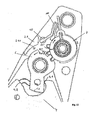
- FIG. 3 shows a further embodiment of a device 100 according to the invention, also a tilt adjuster for the back of a seat of a vehicle.
- the device 100 also has the first fitting part 1, the second fitting part 2, the latch 4 and the latch plate 6 on.
- the second fitting part 2 is rotatable relative to the first fitting part 1 about the rotation axis 3.
- the latching pawl 4 has the toothing 5 as a form-locking and / or force-locking means with which it is in engagement with the counter-toothing 5.1 of the first fitting part 1.
- the latching pawl 4 is secured by the latching plate 6 in the latching position R and is adjustable in the release position F, in which the device 100 is unlocked.
- the device 100 also has a drive means 7 with a securing segment 7.1 and a second segment 7.2 that is rotatable about the drive shaft 9.
- FIGS. 1 and 2 In contrast to the devices 100 according to the invention FIGS. 1 and 2 is the first form and / or adhesion means 7.11 - 7.1i of the fuse segment 7.1 a securing means 10 in the form of a hook, the non-positive and / or positive locking in the locking position R of the latch plate 6 with the front locking tooth 11 of the third form and / or adhesion means 6.1 of the latch plate 6 cooperates.
- the device 100 has a first power means 8.1 and a second power means 8.2, wherein the securing segment 7.1 is adjustable against the force of the first power means 8.1 and the second segment 7.2 against the force of the second power means 8.2. Both force means 8.1, 8.2 therefore hold the latch plate 6 in the latching position R.
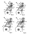
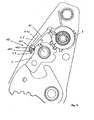
- FIG. 4 shows the latch plate 6 in an enlarged section of the device 100 of FIG. 3 in the locking position R and the drive means 7 in de. Securing position S.
- the latching plate 6 Under the action of external forces acting, for example, on the latching pawl 4, the latching plate 6 can not open unintentionally, since the securing means 10 positively and / or non-positively cooperates with the locking tooth 11 and therefore blocks the adjustment of the latching plate 6.
- FIG. 5 shows the unlocking of the device 100 of Figures 3 and 4 , wherein the latching plate 6 is shown in the latching position R, R 'and in the release position F and wherein the drive means 7 is shown in the drive position A.
- a handle not shown, which generates via a spline shaft 12 of the drive means, which abuts the drive shaft 9, initiated torque, the securing means 10 is rotated against the force of the first force means 8.1, to the locking tooth 11 is no longer encompassed by the hook-like securing means 10. This is essentially no additional adjustment of the drive means 7, so essentially no additional idle required.
- the first and second force means are preferably springs.
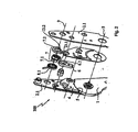
- FIG. 6 shows the device according to the invention with a drive means analogous to that of FIGS. 4 and 5 in an exploded view.
- This embodiment also comprises two substantially identical second fitting part components 2.1, which are arranged parallel to one another and between which the first fitting part 1, the latching pawl 4, the latching plate 6 and the drive means 7 are arranged.
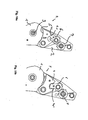
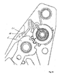
- FIG. 7 shows a further embodiment of a device 100 according to the invention.
- the securing segment 7.1 as a securing means 10, a link and an adjusting means 15, wherein the adjusting means 15 is a bolt which is adjustable along the link.
- the adjusting means 15 is also guided along a guide means 14 of the second fitting part 2.
- the guide means 14 is also a backdrop.
- the terms adjustment means 15 and bolt are used synonymously.
- the FIG. 7 shows the locking plate 6 in the locking position R and the securing segment 7.1 of the drive means 7 in the securing position S.
- the bolt 15 along a contour 16 of the front locking tooth 11 of the third form and / or adhesion means 6.1 of the latch plate 6 adjusted.
- the latching plate 6 is simultaneously adjusted by means of the second form and / or adhesion means 7.21 - 7.2i of the second segment 7.2.
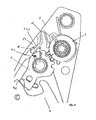
- FIG. 8 shows the device 100 of the invention FIG. 7 ,
- the FIG. 8a shows the locked state of the device 100. If the drive means 7 is not adjusted, the latch plate 6 is by the bolt 15 in each locking position R. secured.
- the FIG. 8b shows a position of the securing segment 7.1 when adjusting the securing segment 7.1 of the securing position S in the drive position A. The latch plate 6 is still in the locking position R.
- the guide means 14 has a curvature, so that an adjustment of the bolt 15 is prevented due to a large load. The curvature is further provided so that the adjustment of the bolt 15 in the drive position A of the fuse segment 7.1 or in the release position F of the latch plate 6 is easy.
- FIG. 8c shows the fuse segment 7.1 in the drive position A.
- the latch plate 6 is in the release position F.
- the latch pawl 4, which is not shown here, or the device 100 is unlocked.
- FIG. 9 shows a further device 100 according to the invention with a securing means 10 with a link and a bolt 15 and a guide means 14 in the form of a backdrop.
- the guide means 14 has a curvature, or the latching plate 6 has a contour 16, through which an additional adjustment of the drive means 7, ie an idle, is required, before the securing segment 7.1 has reached the drive position A, in which the latching plate 6 of the locking position R in the release position F is adjustable.
- the latching segment is still in the safety position S.
- the latching plate 6 is in the latching position R.
- the circle K shows the engagement of the second positive and / or positive connection clamp 7.21 - 7.2i of the second segment 7.2 with the third mold and / or adhesion means in 6.1 of the latching plate 6.
- the second and third form and / or adhesion means 7.21 - 7.2i, 6.1 are not completely engaged with each other.
- FIGS. 7 to 9 can be integral with the drive means 7, so that the securing segment 7.1 and the second segment 7.2 - apart from the bolt 15 of the securing means 10 - are in one piece.
- the adjustment of the seat according to the requirements is therefore simple and inexpensive possible in the modular principle.
- FIG. 10 shows a device 100 according to the invention, however, without the blocking and the securing means.
- the device 100 is a recliner for adjusting the inclination of a backrest of a seat, which is not shown, with respect to the seat part of the seat, which is also not shown, wherein a first fitting part 1 on the seat part and a second fitting part 2 on the Lean back of the seat are arranged. Therefore, the first and the second fitting part 1, 2 on a common axis of rotation 3, so that by turning the second fitting part 2 about the rotation axis 3, the second fitting part 2 relative to the first fitting part 1 is adjustable.
- the device 100 has a latching pawl 4 with form and / or force-locking means 5, here a toothing, as well as a latching plate 6.
- the latching plate 6 acts in its latching position R (see. FIG. 10a ) positively and / or non-positively with the Verrastklinke 4, which in turn cooperates in a latching position R positive and / or non-positively with the counter-toothing of the first fitting part 1.
- the positive and / or frictional connection between the latching plate 6 and the latching pawl 4 takes place through an interaction of the surfaces 6.1 or 4.2.
- the latching pawl 4 is rotatably arranged on the second fitting part 2, so that both the second fitting part 2 and the latching pawl 4 must be locked in the latching position R relative to the first fitting part 1.
- the latching plate 6 is reversible from the latching position R (see. FIG. 10a ) in a counterclockwise direction to a release position F (see. FIG. 10b ) by means of a drive means 7 adjustable.
- the release position F the latching plate 4 cooperates with the latching pawl 6 in such a way that the latching plate 4 rotates in the clockwise direction.
- the latch plate 6 presses against the face 4.1 of the latching pawl and turns it clockwise.
- the latching pawl 4 no longer acts positively and / or non-positively with the first fitting part 1.
- the device 100 is therefore unlocked in the release position F.
- the device 100 In a heavy load on the locked seat, especially in an accident, the latch plate 6, for example, due to inertia, tries to turn counterclockwise, which can lead to unlocking the Verratklinke 4.
- the device 100 according to the invention has a blocking and a securing means, the function of which will be explained with reference to the following figures.
- FIG. 11 shows an embodiment of the device according to the invention in the locked and locked state in which an unwanted self-opening of the recliner is excluded.
- a blocking means in the present case arranged on the fitting 2 projection 2.1, on.
- a safety ball 10 is arranged between the projection 2.1 and the latching plate 6.
- This ball 10 is connected to the drive 7 with an elastically resilient connecting means 11, wherein the composite and / or the drive 7 are designed so that the connecting means 11 is only taken in the respective direction of rotation of the drive 7, if this mechanically or manually ; ie wanted, but not induced by a crash takes place.
- the drive 7 and the connecting means 11 are designed and coordinated so that the ball 10 is spent in a very specific position in the gap, in which there is still the smallest possible clearance between the ball and the adjacent contours 6.1 and 2.1.1 , Furthermore, the drive 7 is designed so that at its intended rotation in a clockwise direction, first the ball 10 is at least partially removed from the gap 12 before latch plate 6 begins to rotate. Furthermore, from the FIG. 11 It can be seen that the ball 10 is disposed between the contour 2.1.1 of the projection 2.1 and the contour 6.1 of the latching plate 6, wherein in normal operation between the contours and the ball 10 at least one side a certain game (not shown). This game allows the adjustment of the two plates 1, 2 to each other.
- the contour 6.1 is designed as a curve whose radius increases in a clockwise direction, so that the radius R "6.1 is greater than the radius R'6.1
- the ball 10 thus prevents the latch plate 6 automatically unintentionally rotated counterclockwise and thus the engagement of the surfaces 4.2 and 6.2 is repealed.
- FIG. 12 shows the device according to FIG. 11 in unlocked and unlocked state.
- the drive 7 was manually or mechanically; ie intentionally rotated in a clockwise direction, which can be recognized by means of the marking lines 13 'and 13 ", which, in contrast to the illustration according to FIG. 11 do not cover up anymore.
- the connecting means 11 was first taken and thus at first partially pulled out of the gap 12, the ball 10 at least partially. Slightly offset in time, the drive 7, the latch plate 6, as shown by the arrow, rotated counterclockwise and thus repealed the latching engagement between the surfaces 4.2 and 6.2.
- FIG. 13 shows the so-called “min-material position”, ie the position at which all tolerances accumulate in such a way that the gap 12 its maximum size reached.
- the ball 10 is positioned by the drive 7 or the connecting means 11 very deep into the gap 12, so that in the event of a crash, the latch plate 6 must perform only a very small rotation before the blocking function of the ball 10 occurs , This minimum free travel of the latch plate 6 causes no loss of strength of the recliner occurs.
- FIG. 14 is the so-called "max-material position” shown, ie the position at which the manufacturing tolerances add up so that the gap 12 is minimal in the context of manufacturing tolerances.
- the ball 10 is positioned by the drive 7 and the connecting means 11 to the upper end of the gap 12 and acts there blocking, without the functioning of the fuse is impaired. Otherwise, the comments on FIG. 4 directed.
- FIG. 15 shows essentially the device according to the FIGS. 11 to 14 ,
- the ball 10 has been replaced by a freewheeling element 10.2, which is rotatable only counterclockwise about the plane of rotation extending into the plane of the paper 10.1.
- the freewheel element has a spring means 10.3, the freewheel element biases in a clockwise direction.
- the connecting means 11 is not resilient, but substantially rigid, but equipped on the drive 7 with a swivel executed.
- the contours 6.1 and 2.1.1 are not equipped with a rising, but provided with a constant or to the output of the gap 12 decreasing slope contour.
- the freewheeling element is positioned by the drive 7 or by the connecting means 11 at a location in the gap 12 at which there is no play between the freewheeling element 10.2 and the contours 6.1 and 2.1.1.
- the displacement of the freewheeling element must be such that the freewheeling element is not blocked. Since the freewheeling element 10.2 in the present case is only rotatable counterclockwise in the present case, it prevents the rotation of the latching plate 6 in the clockwise direction in the event of a crash. Otherwise, the device works according to FIG. 15 analogous to the device according to the FIGS. 11-14 ,
- FIG. 16 Is the device according to FIG. 15 shown in the unlocked state.
- the freewheeling element 10.2 has been pulled by the drive 7 to the upper end of the gap 12, where it no longer acts locking on the latch plate 6, thus can also be rotated by the drive 7 counterclockwise, so that the latch plate 6 is no longer locking together with the latching pawl 4 acts.
- the displacement of the freewheeling element must be such that the freewheeling element is not blocked.
Landscapes
- Engineering & Computer Science (AREA)
- Aviation & Aerospace Engineering (AREA)
- Transportation (AREA)
- Mechanical Engineering (AREA)
- Chairs For Special Purposes, Such As Reclining Chairs (AREA)
- Seats For Vehicles (AREA)
- Lock And Its Accessories (AREA)
Applications Claiming Priority (3)
| Application Number | Priority Date | Filing Date | Title |
|---|---|---|---|
| DE200510030050 DE102005030050B3 (de) | 2005-06-27 | 2005-06-27 | Sicherung eines Kraftfahrzeugsitzbeschlages |
| DE102005037832A DE102005037832B4 (de) | 2005-02-25 | 2005-08-08 | Vorrichtung zum Verriegeln und Entriegeln mit einer Sicherung gegen Selbstöffnung |
| EP06776085.0A EP1899194B1 (fr) | 2005-06-27 | 2006-06-27 | Dispositif concu pour assurer un blocage et un deblocage au moyen d'un systeme de securite afin de proteger contre une ouverture automatique |
Related Parent Applications (2)
| Application Number | Title | Priority Date | Filing Date |
|---|---|---|---|
| EP06776085.0A Division-Into EP1899194B1 (fr) | 2005-06-27 | 2006-06-27 | Dispositif concu pour assurer un blocage et un deblocage au moyen d'un systeme de securite afin de proteger contre une ouverture automatique |
| EP06776085.0 Division | 2006-06-27 |
Publications (2)
| Publication Number | Publication Date |
|---|---|
| EP2351663A2 true EP2351663A2 (fr) | 2011-08-03 |
| EP2351663A3 EP2351663A3 (fr) | 2011-12-28 |
Family
ID=37074252
Family Applications (3)
| Application Number | Title | Priority Date | Filing Date |
|---|---|---|---|
| EP11002173.0A Not-in-force EP2374655B1 (fr) | 2005-06-27 | 2006-06-27 | Dispositif de verrouillage et de déverrouillage doté d'une sécurité contre l'ouverture automatique |
| EP11002172A Withdrawn EP2351663A3 (fr) | 2005-06-27 | 2006-06-27 | Dispositif de blocage et déblocage avec un moyen de sécurité afin de empêcher une overture automatique |
| EP06776085.0A Not-in-force EP1899194B1 (fr) | 2005-06-27 | 2006-06-27 | Dispositif concu pour assurer un blocage et un deblocage au moyen d'un systeme de securite afin de proteger contre une ouverture automatique |
Family Applications Before (1)
| Application Number | Title | Priority Date | Filing Date |
|---|---|---|---|
| EP11002173.0A Not-in-force EP2374655B1 (fr) | 2005-06-27 | 2006-06-27 | Dispositif de verrouillage et de déverrouillage doté d'une sécurité contre l'ouverture automatique |
Family Applications After (1)
| Application Number | Title | Priority Date | Filing Date |
|---|---|---|---|
| EP06776085.0A Not-in-force EP1899194B1 (fr) | 2005-06-27 | 2006-06-27 | Dispositif concu pour assurer un blocage et un deblocage au moyen d'un systeme de securite afin de proteger contre une ouverture automatique |
Country Status (6)
| Country | Link |
|---|---|
| US (2) | US8070231B2 (fr) |
| EP (3) | EP2374655B1 (fr) |
| JP (1) | JP5033796B2 (fr) |
| KR (1) | KR101274375B1 (fr) |
| CN (1) | CN101228044B (fr) |
| WO (1) | WO2007000307A2 (fr) |
Cited By (1)
| Publication number | Priority date | Publication date | Assignee | Title |
|---|---|---|---|---|
| DE102012008702A1 (de) * | 2012-04-28 | 2013-10-31 | Faurecia Autositze Gmbh | Verstelleinrichtung für einen Fahrzeugsitz |
Families Citing this family (25)
| Publication number | Priority date | Publication date | Assignee | Title |
|---|---|---|---|---|
| DE102007042604B4 (de) * | 2006-11-17 | 2014-09-25 | Johnson Controls Gmbh | Fahrzeugsitz mit einem Neigungsversteller mit Freischwenkfunktionalität |
| EP2144783A1 (fr) * | 2007-03-09 | 2010-01-20 | Johnson Controls GmbH | Siège de véhicule comportant une partie inclinable oscillante |
| US8783775B2 (en) * | 2008-10-23 | 2014-07-22 | Johnson Controls Technology Company | Locking device, especially for an adjustment fitting and especially for a vehicle seat, and vehicle seat |
| DE102008052893B4 (de) * | 2008-10-23 | 2016-03-24 | Johnson Controls Gmbh | Verriegelungsvorrichtung, insbesondere für einen Verstellbeschlag und insbesondere für einen Fahrzeugsitz, und Fahrzeugsitz |
| DE102009032904A1 (de) * | 2009-05-12 | 2010-11-25 | Johnson Controls Gmbh | Vorrichtung zum Verriegeln und Entriegeln eines ersten Beschlagteils und eines zweiten Beschlagteils, insbesondere eines Kraftfahrzeugsitzes, relativ zueinander |
| JP5597013B2 (ja) * | 2010-04-01 | 2014-10-01 | テイ・エス テック株式会社 | 自動車用シートの両持ち式リクライニングロック装置 |
| DE102010019697B4 (de) * | 2010-05-05 | 2013-10-17 | Keiper Gmbh & Co. Kg | Beschlag für einen Fahrzeugsitz und Fahrzeugsitz |
| US9056563B2 (en) * | 2011-03-11 | 2015-06-16 | Johnson Controls Gmbh | Adjustment means for a vehicle seat |
| DE102011106284B4 (de) * | 2011-07-01 | 2022-10-20 | Keiper Seating Mechanisms Co., Ltd. | Beschlagsystem für einen Fahrzeugsitz und Fahrzeugsitz |
| DE102011052059B4 (de) * | 2011-07-22 | 2021-07-22 | Adient Luxembourg Holding S.À R.L. | Sitzbeschlag für einen Kraftfahrzeugsitz |
| IN2014DN08535A (fr) | 2012-05-07 | 2015-05-15 | Johnson Controls Tech Co | |
| DE102012013208B4 (de) * | 2012-05-07 | 2019-07-25 | Adient Luxembourg Holding S.À R.L. | Sitzteil eines Fahrzeugsitzes |
| JP5865518B2 (ja) * | 2012-06-26 | 2016-02-17 | ジョンソン コントロールズ コンポーネンツ ゲーエムベーハー ウントコンパニー カーゲー | 車両シート用継手及び車両シート |
| US9249827B2 (en) * | 2012-12-21 | 2016-02-02 | Taco Metals, Inc. | Hinge employing a ratchet for an upholstery seat |
| US8875347B2 (en) * | 2012-12-21 | 2014-11-04 | Taco Metals; Inc. | Hinge employing a ratchet for an upholstery seat |
| FR3004393B1 (fr) * | 2013-04-12 | 2016-09-09 | Faurecia Sieges Automobile | Mecanisme de liaison pivotante pour siege de vehicule et siege comprenant un tel mecanisme |
| KR101395927B1 (ko) * | 2013-05-28 | 2014-05-19 | 현대자동차주식회사 | 후방충돌 발생 시 변속레버의 이동방지 구조 |
| DE102014111923B4 (de) * | 2014-08-20 | 2017-03-30 | Volkswagen Aktiengesellschaft | Armlehne mit Crashsicherung |
| CN106314220A (zh) * | 2015-06-17 | 2017-01-11 | 上汽通用五菱汽车股份有限公司 | 一种汽车座椅折叠机构 |
| JP6809161B2 (ja) * | 2016-11-21 | 2021-01-06 | トヨタ紡織株式会社 | 乗物用シート |
| DE102017204703A1 (de) | 2017-03-21 | 2018-09-27 | Brose Fahrzeugteile Gmbh & Co. Kg, Coburg | Fahrzeugsitz mit Beschlaganordnung und Sperrvorrichtung an unterschiedlichen Längsseiten |
| CN108016338A (zh) * | 2017-11-29 | 2018-05-11 | 延锋安道拓座椅有限公司 | 一种翻转机构 |
| SE544527C2 (en) | 2019-01-18 | 2022-07-05 | Flokk Ab | A tilt locking device for a chair seat |
| CN113771932A (zh) * | 2021-07-22 | 2021-12-10 | 浙江翱力新材料科技有限公司 | 一种重载型搬运车 |
| KR20240076911A (ko) * | 2022-11-24 | 2024-05-31 | 현대자동차주식회사 | 자동차용 전동식 시트의 수동식 시트백 폴딩 장치 |
Citations (1)
| Publication number | Priority date | Publication date | Assignee | Title |
|---|---|---|---|---|
| DE10048127A1 (de) | 2000-09-28 | 2002-04-18 | Keiper Gmbh & Co | Beschlag für einen Fahrzeugsitz |
Family Cites Families (12)
| Publication number | Priority date | Publication date | Assignee | Title |
|---|---|---|---|---|
| US3779655A (en) * | 1971-12-23 | 1973-12-18 | Sanshin Kinzoku Ind Co Ltd | Angle variable joint for foldable chair |
| DE2931915A1 (de) * | 1979-08-07 | 1981-02-26 | Keiper Automobiltechnik Gmbh | Gelenkbeschlag fuer sitze mit verstellbarer rueckenlehne, insbesondere fuer kraftfahrzeugsitze |
| US5310247A (en) * | 1992-03-23 | 1994-05-10 | Araco K.K. | Vehicle seats |
| DE19633782C1 (de) * | 1996-08-22 | 1998-03-26 | Keiper Recaro Gmbh Co | Rastbeschlag mit Knickfeder |
| DE19654395C1 (de) * | 1996-12-27 | 1998-02-12 | Faure Bertrand Sitztech Gmbh | Nocken zur lösbaren Verriegelung eines Bauteils, insbesondere an einem Kraftfahrzeugsitz |
| WO2001062540A1 (fr) * | 2000-02-25 | 2001-08-30 | Volkswagen Ag | Dispositif de reglage de dossiers de sieges de vehicules, notamment de vehicules automobiles |
| US6502903B2 (en) * | 2001-01-11 | 2003-01-07 | Bae Industries, Inc. | Seat integrated latch recliner assembly with inertial locking mechanism |
| US6644746B2 (en) * | 2001-01-11 | 2003-11-11 | Bae Industries, Inc. | Seat integrated latch recliner assembly with inertial locking mechanism |
| CN2524986Y (zh) * | 2001-11-05 | 2002-12-11 | 江苏省溧阳市汽车座椅调角器总厂 | 座椅调角器 |
| DE10312140B4 (de) * | 2003-03-19 | 2006-10-05 | Johnson Controls Gmbh | Feststell- und Neigungsverstellvorrichtung für Beschläge |
| US6860560B2 (en) * | 2003-03-25 | 2005-03-01 | Porter Group, Llc | Seat back recliner for vehicles |
| ATE390316T1 (de) * | 2004-10-01 | 2008-04-15 | Johnson Controls Gmbh | Verstellvorrichtung und fahrzeugsitz |
-
2006
- 2006-06-27 EP EP11002173.0A patent/EP2374655B1/fr not_active Not-in-force
- 2006-06-27 KR KR1020077030477A patent/KR101274375B1/ko active Active
- 2006-06-27 WO PCT/EP2006/006166 patent/WO2007000307A2/fr not_active Ceased
- 2006-06-27 JP JP2008518697A patent/JP5033796B2/ja active Active
- 2006-06-27 EP EP11002172A patent/EP2351663A3/fr not_active Withdrawn
- 2006-06-27 CN CN2006800231438A patent/CN101228044B/zh active Active
- 2006-06-27 EP EP06776085.0A patent/EP1899194B1/fr not_active Not-in-force
-
2007
- 2007-12-26 US US11/964,453 patent/US8070231B2/en active Active
-
2011
- 2011-11-30 US US13/307,240 patent/US8388068B2/en active Active
Patent Citations (1)
| Publication number | Priority date | Publication date | Assignee | Title |
|---|---|---|---|---|
| DE10048127A1 (de) | 2000-09-28 | 2002-04-18 | Keiper Gmbh & Co | Beschlag für einen Fahrzeugsitz |
Cited By (2)
| Publication number | Priority date | Publication date | Assignee | Title |
|---|---|---|---|---|
| DE102012008702A1 (de) * | 2012-04-28 | 2013-10-31 | Faurecia Autositze Gmbh | Verstelleinrichtung für einen Fahrzeugsitz |
| DE102012008702B4 (de) | 2012-04-28 | 2018-12-06 | Faurecia Autositze Gmbh | Verstelleinrichtung für einen Fahrzeugsitz und Fahrzeugsitz |
Also Published As
| Publication number | Publication date |
|---|---|
| EP2374655A3 (fr) | 2011-12-28 |
| CN101228044A (zh) | 2008-07-23 |
| JP5033796B2 (ja) | 2012-09-26 |
| WO2007000307A3 (fr) | 2007-03-15 |
| EP2374655A2 (fr) | 2011-10-12 |
| EP1899194B1 (fr) | 2016-06-22 |
| CN101228044B (zh) | 2011-11-16 |
| KR101274375B1 (ko) | 2013-06-14 |
| EP1899194A2 (fr) | 2008-03-19 |
| EP2351663A3 (fr) | 2011-12-28 |
| KR20080019645A (ko) | 2008-03-04 |
| US8388068B2 (en) | 2013-03-05 |
| US20120091776A1 (en) | 2012-04-19 |
| JP2008546594A (ja) | 2008-12-25 |
| EP2374655B1 (fr) | 2016-08-17 |
| US20100096897A1 (en) | 2010-04-22 |
| US8070231B2 (en) | 2011-12-06 |
| WO2007000307A2 (fr) | 2007-01-04 |
Similar Documents
| Publication | Publication Date | Title |
|---|---|---|
| EP2374655B1 (fr) | Dispositif de verrouillage et de déverrouillage doté d'une sécurité contre l'ouverture automatique | |
| DE102006009976B4 (de) | Radialverstellmechanismus zur Anwendung in einer Fahrzeugsitzbaugruppe | |
| EP1673255B1 (fr) | Dispositif de verrouillage pour siege de vehicule | |
| DE102008063639B4 (de) | Gurtaufroller mit schaltbarem Gurtkraftbegrenzer | |
| DE2911504A1 (de) | Neigungsverstellvorrichtung fuer sitze | |
| DE3038912A1 (de) | Gelenkbeschlag fuer fahrzeugsitze mit einer neigungseinstellbaren rueckenlehne | |
| EP1884611A2 (fr) | Serrure de véhicule automobile | |
| EP2352660A1 (fr) | Siège de véhicule muni d'un système à cliquet | |
| EP1805058A2 (fr) | Dispositif de reglage et siege de vehicule | |
| EP1337417A2 (fr) | Siege de vehicule automobile | |
| EP2337705A1 (fr) | Dispositif de verrouillage, destiné en particulier à une ferrure de réglage en particulier pour un siège de véhicule, et siège de véhicule | |
| EP1395459A2 (fr) | Siege de vehicule automobile | |
| DE10052092B4 (de) | Einstellbeschlag für einen Fahrzeugsitz | |
| DE102005037832B4 (de) | Vorrichtung zum Verriegeln und Entriegeln mit einer Sicherung gegen Selbstöffnung | |
| DE602004009566T2 (de) | Autokindersitz, schwenkbar zwischen einer nach vorne und einer türwärts gerichteten Position , mit einer automatischen Rückstellung nach vorne | |
| EP1735182B1 (fr) | Dispositif de verrouillage et/ou de deverrouillage d'un composant, en particulier dans/ou sur un vehicule, et procede y relatif | |
| EP1776252B1 (fr) | Siège de vehicule à moteur | |
| WO2006089853A1 (fr) | Dispositif pour verrouiller et deverrouiller une securite contre l'ouverture automatique | |
| EP2100780B1 (fr) | Système de protection contre les tonneaux avec un arceau extensible | |
| DE102014216951B3 (de) | Verriegelungsvorrichtung | |
| EP1033279B1 (fr) | Articulation pour un siège de véhicule | |
| DE102005030050B3 (de) | Sicherung eines Kraftfahrzeugsitzbeschlages | |
| WO1997046414A1 (fr) | Siege automobile avec dispositif de reglage de l'inclinaison du dossier et systeme de securite additionnel | |
| DE10346148B4 (de) | Vorrichtung zur Verriegelung und zur Entriegelung, insbesondere eines Beschlags zur Verstellung von Teilen eines Fahrzeugsitzes, und Verfahren | |
| DE69514522T2 (de) | Unbegrenzt verstellbarer Gleitschienenverriegelungsmechanismus |
Legal Events
| Date | Code | Title | Description |
|---|---|---|---|
| PUAI | Public reference made under article 153(3) epc to a published international application that has entered the european phase |
Free format text: ORIGINAL CODE: 0009012 |
|
| AC | Divisional application: reference to earlier application |
Ref document number: 1899194 Country of ref document: EP Kind code of ref document: P |
|
| AK | Designated contracting states |
Kind code of ref document: A2 Designated state(s): AT BE BG CH CY CZ DE DK EE ES FI FR GB GR HU IE IS IT LI LT LU LV MC NL PL PT RO SE SI SK TR |
|
| PUAL | Search report despatched |
Free format text: ORIGINAL CODE: 0009013 |
|
| AK | Designated contracting states |
Kind code of ref document: A3 Designated state(s): AT BE BG CH CY CZ DE DK EE ES FI FR GB GR HU IE IS IT LI LT LU LV MC NL PL PT RO SE SI SK TR |
|
| RIC1 | Information provided on ipc code assigned before grant |
Ipc: B60N 2/235 20060101AFI20111124BHEP |
|
| 17P | Request for examination filed |
Effective date: 20120628 |
|
| STAA | Information on the status of an ep patent application or granted ep patent |
Free format text: STATUS: THE APPLICATION IS DEEMED TO BE WITHDRAWN |
|
| 18D | Application deemed to be withdrawn |
Effective date: 20150103 |