EP2351663A2 - Locking and releasing mechanism comprising a safety means to prevent self-opening - Google Patents
Locking and releasing mechanism comprising a safety means to prevent self-opening Download PDFInfo
- Publication number
- EP2351663A2 EP2351663A2 EP11002172A EP11002172A EP2351663A2 EP 2351663 A2 EP2351663 A2 EP 2351663A2 EP 11002172 A EP11002172 A EP 11002172A EP 11002172 A EP11002172 A EP 11002172A EP 2351663 A2 EP2351663 A2 EP 2351663A2
- Authority
- EP
- European Patent Office
- Prior art keywords
- latching
- securing
- drive
- segment
- plate
- Prior art date
- Legal status (The legal status is an assumption and is not a legal conclusion. Google has not performed a legal analysis and makes no representation as to the accuracy of the status listed.)
- Withdrawn
Links
- 238000000034 method Methods 0.000 claims abstract description 5
- 230000000903 blocking effect Effects 0.000 claims description 12
- 230000007704 transition Effects 0.000 claims description 9
- 230000002441 reversible effect Effects 0.000 claims description 2
- 238000004519 manufacturing process Methods 0.000 description 10
- 239000002981 blocking agent Substances 0.000 description 3
- 230000008901 benefit Effects 0.000 description 2
- 238000006073 displacement reaction Methods 0.000 description 2
- 230000003993 interaction Effects 0.000 description 2
- 239000000463 material Substances 0.000 description 2
- 230000009471 action Effects 0.000 description 1
- 230000002411 adverse Effects 0.000 description 1
- 230000004888 barrier function Effects 0.000 description 1
- 230000005540 biological transmission Effects 0.000 description 1
- 239000002131 composite material Substances 0.000 description 1
- 230000003247 decreasing effect Effects 0.000 description 1
- 230000001771 impaired effect Effects 0.000 description 1
- 230000014759 maintenance of location Effects 0.000 description 1
- 230000036961 partial effect Effects 0.000 description 1
- 230000002829 reductive effect Effects 0.000 description 1
- 230000000630 rising effect Effects 0.000 description 1
Images


Classifications
-
- B—PERFORMING OPERATIONS; TRANSPORTING
- B60—VEHICLES IN GENERAL
- B60N—SEATS SPECIALLY ADAPTED FOR VEHICLES; VEHICLE PASSENGER ACCOMMODATION NOT OTHERWISE PROVIDED FOR
- B60N2/00—Seats specially adapted for vehicles; Arrangement or mounting of seats in vehicles
- B60N2/02—Seats specially adapted for vehicles; Arrangement or mounting of seats in vehicles the seat or part thereof being movable, e.g. adjustable
- B60N2/22—Seats specially adapted for vehicles; Arrangement or mounting of seats in vehicles the seat or part thereof being movable, e.g. adjustable the back-rest being adjustable
- B60N2/235—Seats specially adapted for vehicles; Arrangement or mounting of seats in vehicles the seat or part thereof being movable, e.g. adjustable the back-rest being adjustable by gear-pawl type mechanisms
- B60N2/2352—Seats specially adapted for vehicles; Arrangement or mounting of seats in vehicles the seat or part thereof being movable, e.g. adjustable the back-rest being adjustable by gear-pawl type mechanisms with external pawls
-
- B—PERFORMING OPERATIONS; TRANSPORTING
- B60—VEHICLES IN GENERAL
- B60N—SEATS SPECIALLY ADAPTED FOR VEHICLES; VEHICLE PASSENGER ACCOMMODATION NOT OTHERWISE PROVIDED FOR
- B60N2/00—Seats specially adapted for vehicles; Arrangement or mounting of seats in vehicles
- B60N2/24—Seats specially adapted for vehicles; Arrangement or mounting of seats in vehicles for particular purposes or particular vehicles
- B60N2/42—Seats specially adapted for vehicles; Arrangement or mounting of seats in vehicles for particular purposes or particular vehicles the seat constructed to protect the occupant from the effect of abnormal g-forces, e.g. crash or safety seats
- B60N2/43—Safety locks
-
- Y—GENERAL TAGGING OF NEW TECHNOLOGICAL DEVELOPMENTS; GENERAL TAGGING OF CROSS-SECTIONAL TECHNOLOGIES SPANNING OVER SEVERAL SECTIONS OF THE IPC; TECHNICAL SUBJECTS COVERED BY FORMER USPC CROSS-REFERENCE ART COLLECTIONS [XRACs] AND DIGESTS
- Y10—TECHNICAL SUBJECTS COVERED BY FORMER USPC
- Y10T—TECHNICAL SUBJECTS COVERED BY FORMER US CLASSIFICATION
- Y10T403/00—Joints and connections
- Y10T403/32—Articulated members
- Y10T403/32254—Lockable at fixed position
- Y10T403/32262—At selected angle
-
- Y—GENERAL TAGGING OF NEW TECHNOLOGICAL DEVELOPMENTS; GENERAL TAGGING OF CROSS-SECTIONAL TECHNOLOGIES SPANNING OVER SEVERAL SECTIONS OF THE IPC; TECHNICAL SUBJECTS COVERED BY FORMER USPC CROSS-REFERENCE ART COLLECTIONS [XRACs] AND DIGESTS
- Y10—TECHNICAL SUBJECTS COVERED BY FORMER USPC
- Y10T—TECHNICAL SUBJECTS COVERED BY FORMER US CLASSIFICATION
- Y10T74/00—Machine element or mechanism
- Y10T74/20—Control lever and linkage systems
- Y10T74/20576—Elements
- Y10T74/20636—Detents
- Y10T74/20648—Interrelated lever release
Definitions
- the present invention relates to devices, in particular for a motor vehicle seat, with which the adjustment of a first fitting part and a second fitting part is locked and unlocked relative to each other, with a drive means and a latching plate, wherein the latching plate is reversibly adjustable by means of the drive means, wherein the latching plate Adjusting the fittings locked relative to each other in a locking position and unlocked in a release position. Furthermore, the present invention relates to a device for locking and unlocking, a seat with a device according to the invention and a method for securing a device against self-opening.
- the object is achieved with a device, in particular for a motor vehicle seat, with which the adjustment of a first fitting part and a second fitting part relative to each other can be locked and unlocked, with a drive means, a latch plate (6) and a latching pawl (4), wherein the Verrastklinke (4) is lockable relative to this by latching with the first fitting part (1), wherein the latching plate is reversibly adjustable by means of the drive means, wherein the latching plate locks the Verrastklinke in a latching position and unlocked in a release position, wherein the drive means is a securing segment for securing the latch plate against self-opening.
- the latch plate Due to the additional securing segment of the drive means the latch plate is secured against self-opening. The latch plate therefore remains safely at high loads in the locked position and locks the latch pawl, so that the device is locked.
- a detent position according to the invention is any position of the latch plate in which the latch plate locks the latch pawl.
- a release position according to the invention is any position of the latch plate in which it does not lock the Verrastklinke.
- the presence of the securing segment makes it possible to optimize the locking angle-in that the unlocking is easier and therefore more comfortable for the user.
- the space created by the securing segment can be used for a comfort-oriented design.
- a preferred embodiment which also achieves the object, is a device for locking and unlocking, in particular a fitting for stiffening parts of a seat, in particular a motor vehicle seat, having a first fitting part, a latching pawl and at least one latching plate, wherein the latching pawl Locking with the first fitting part can be locked relative to this, wherein the latching plate is adjustable in a latching locking position and in a non-latching release position, wherein the device comprises a drive means, at least partially is reversibly adjustable from a drive position to a securing position, wherein the adjustment of the latching plate from the locking position to the release position only in the drive position is possible.
- the drive means must be at least partially adjusted in the drive position, so that the latch plate can be moved to the release position. As long as the drive means is not driven, therefore, an unintentional adjustment of the latch plate, and therefore a self-opening of the device in which the latch plate is moved from the latching position to the release position, not possible. Also in this embodiment, the device remains securely locked at high loads in the locking position.
- the drive means preferably has a securing segment and a second segment.
- the latching plate is therefore either only by means of the second segment or by means of the second segment and the securing segment together from the locking position to the release position and back adjustable.
- the drive means is rotatable about a drive axis, wherein the securing segment is adjustable by rotating the drive means about the drive axis from the securing position to the drive position and the latch plate by rotating the drive means about the drive axis from the latching position to the release position and back. Therefore, the drive of the fuse segment takes place on the same axis as the drive of the locking and unlocking of the device. There are no other components needed to operate the fuse segment.
- the drive means is actuated by means of a handle.
- a handle actuated by means of a handle.
- an electrical operation is possible.
- the second segment is rotatable about the drive axis against the force of a second force means, so that the latch plate is held in the latching position by means of the force of the second force means.
- the securing segment has a first positive and / or positive locking means and the second segment has a second positive and / or frictional means, wherein the first and the second positive and / or frictional means at least partially with a third positive and / or frictional means Locking plate are engaged. Due to the mutual engagement of the positive and / or positive locking means, a load on the latching plate also acts positively and / or non-positively on the drive means, in particular on the securing segment.
- the third form and / or frictional engagement means of the latch plate is a toothing.
- the first form and / or Kraft gleichmfttel and the second form and / or adhesion means are each at least two teeth with the same tooth spacing, the transition tooth spacing between the front tooth of the first positive and / or frictional means and the rear tooth of second form and / or frictional means adjacent to each other, not equal to the tooth spacing, preferably larger.
- the transition tooth spacing is therefore a deliberate pitch error of the toothing of the drive means or between the securing segment and the second segment, which allows idling, by the unlocking of the device is very uniformly possible when the unlocking is done by the drive means.
- transition tooth spacing between the teeth of the securing segment and the teeth of the second segment leads to a collision of the toothing of the latching plate with that of the drive means in the case of a large load acting on the latching plate, which tends to self-open.
- the latch plate is therefore adjusted, in particular due to tolerances, slightly, but is then stopped safely by the collision, so that the latch plate remains in the latching position and the device is still securely locked.
- the latching plate is preferably rotatable about a latching axis.
- the idle then corresponds to a rotation angle of the latch plate of about 3 - 5 °.
- the first form and / or Kraft gleichmiftel is a securing means which is in the latching position in engagement with a front latching tooth of the third form and / or adhesion means of the latch plate.
- the adjustment of the latching plate is blocked by the locking position in the release position by interaction of the locking tooth with the securing means.
- the locking tooth preferably engages behind the securing means in the latching position.
- the securing segment is preferably rotatable about the drive axis counter to the force of a first force means, so that the securing segment additionally holds the latching plate in the latching position by means of the force of the first force means.
- the first force means causes the securing segment is held in a position under load, for example when driving the vehicle, and does not rattle.
- the securing means comprises an adjusting means, which rests in the latching position on a contour of the front ratchet tooth.
- the adjustment is adjusted when driving the fuse segment before and / or during the adjustment of the latch plate, so that it does not interfere with the Verrastplatte in the drive position of the fuse segment during adjustment.
- the second segment When driving the drive means, the second segment is adjusted together with the securing segment, so that the securing means does not hinder the locking tooth. Due to tolerances of the device, for example, due to manufacturing or manufacturing tolerances, optionally creates a low idle when adjusting the latch plate from the locking position to the release position. Essentially, however, the adjustment is possible without an additional idle. The unlocking angle is therefore in contrast to the o. G. Embodiment providing deliberate additional idle, smaller.
- the securing segment has at least one stop and the second segment has at least one counter-stop, so that when adjusting the drive means, the second segment is also adjusted by the securing segment.
- the drive means has a splined shaft profile which bears against the drive axle, so that the second segment does not slip when the drive axle is rotated.
- the splitting of the drive means in the securing segment and the second segment allows a considerably greater security against self-opening in the event of an accident.
- the device is easier unlocked.
- the additional component cost is limited to one or two components and is therefore very low.
- the drive means can be quickly and easily assembled by "plugging together”. The additional manufacturing and assembly costs are therefore low.
- Another object of the present invention is a device, in particular for a motor vehicle seat, with which the adjustment of a first fitting part and a second fitting part relative to each other is lockable and unlockable, with a drive means, a latch plate and a latch pawl, wherein the Verrastklinke by latching with the the first fitting part can be locked relative thereto, wherein the latching plate is reversibly adjustable by means of the drive means and the latching plate locks the Verrastklinke in a latching position and unlocked in a release position, in which between the outer contour of the latching plate and a blocking means, on the second fitting part is arranged, a securing means is attachable.
- the device according to the invention succeeds in reliably preventing an automatic unlocking of the latching pawl.
- the device according to the invention is simple and inexpensive to manufacture and assemble. Even at comparatively large Manufacturing tolerances, the device of the invention is functional.
- the blocking agent is preferably designed as a moving barrier, so that it is possible with the device according to the invention to compensate for tolerances and no loss of strength occurs.
- the device has a securing means which is arranged for securing between the latching plate and the blocking means.
- this securing means is connected to the drive means which moves the detent plate into the detent position or into the release position.
- the securing means can either be attached or removed simultaneously with the respective adjustment of the detent plate.
- the securing means may be any securing means known to those skilled in the art.
- the securing means is a ball, a cylinder or a securing means which is rotatably mounted only in one direction.
- the object is also achieved with a seat having a device according to the invention.
- the safety that the device of the seat does not unintentionally solve, especially in an accident, is significantly improved.
- the inclination adjustment does not dissolve even when the backrest is loaded, for example by luggage thrown into the passenger compartment in the event of an accident.
- the occupant of the seat according to the invention therefore provides greater security.
- the seat is easier unlocked.
- a further subject of the present invention is a method for unlocking a device for locking and unlocking, the device having a drive means with a securing segment and a second segment, a latching plate and a latching pawl, wherein the securing segment is moved from a securing position into a drive position, before and / or while the latch plate by means of the drive means from the detent position in which it locks the adjustment of the Verrastklinke (4) so that the device is locked in a release position in which they do not adjust the Verrastklinke (4) locked, so that the device is unlocked, is adjusted.
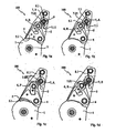
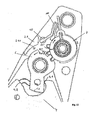
- FIG. 1 shows an embodiment of a device according to the invention 100.
- the device 100 is a recliner for adjusting the inclination of a back of a seat, which is not shown, with respect to the seat part of the seat, which is also not shown, wherein a first fitting part 1 on the Seat part and a second fitting part 2 are arranged on the backrest of the seat. Therefore, the show first and second fitting part 1, 2 a common axis of rotation 3, so that by turning the second fitting part 2 about the axis of rotation 3, the second fitting part 2 relative to the first fitting part 1 is adjustable.
- the device 100 has a latching pawl 4 with form and / or force-locking means 5, here a toothing, as well as a latching plate 6.
- the latching plate 6 acts in its latching position R positively and / or non-positively with the Verrastklinke 4 together, which in turn cooperates in a latching position R form and / or non-positively with a counter toothing 5.1 of the first fitting part 1.
- the latching pawl is rotatably arranged on the second fitting part 2, so that both the second fitting part 2 and the latching pawl 4 are locked in the latching position R relative to the first fitting part 1.
- the latching plate 6 is reversibly adjustable from the latching position R into a release position F by means of a drive means 7.
- the latching plate 4 positively and / or non-positively with the Verrastklinke 6 cooperates, so that the Verrastklinke 6 adjusted, lifted from the first fitting part 1 and not positively and / or non-positively with the first fitting part 1 cooperates.
- the device 100 is therefore unlocked in the release position F.
- the drive means 7 a securing segment 7.1 with a first positive and / or positive locking means 7.11 - 7.1i, here two mutually rigid teeth 7.11, 7.12, and a second segment 7.2 with a second positive and / or non-positive 7.21 - 7.2i, also two mutually rigid teeth 7.21, 7.22, on.
- the teeth 7.11, 7.12, 7.21, 7.22 of the securing and the second segment 7.1, 7.2 have the same tooth spacing 7.00.
- the transition tooth spacing 7.01 between the front tooth 7.11 of the securing segment 7.1 and the rear tooth 7.22 of the second segment 7.2, which bear against one another, in a securing position S of the drive means 7 is greater than the tooth spacing 7.00.
- the teeth 7.11, 7.12, 7.21, 7.22 of the first and second form and / or Kraft gleichmfttels 7.11 - 7.1 i, 7.21 - 7.2i thus have at this transition point on a pitch error.
- the drive means 7 is rotatably arranged about a drive shaft 9 and connected to a handle, not shown.
- Fastened position S in a drive position A preferably against the force of a first power means 8.1, preferably a spring.
- the transition tooth spacing 7.01 between the front tooth 7.11 of the securing segment 7.1 and the rear tooth 7.22 of the second segment 7.2 is reduced until it is substantially equal to the tooth spacing 7.00 of the first and second form and / or adhesion means 7.11 - 7.1 in the drive position A. i, 7.21 - 7.2i, so that the tooth spacing 7.00 and the transition tooth spacing 7.01 on the drive means 7 is uniform.
- the required angle of rotation by which the drive means 7 is rotated from the securing position S to the drive position A about 3 - 5 °.
- the latching plate 6 has third form and / or adhesion means 6.1, here a partial toothing, which are at least partially in engagement with the first and / or second adhesion means 7.11 - 7.1i, 7.21 - 7.2i and cooperate with the rotation of the drive means 7 with these , so that the latching plate 6 is moved from the latching position R to the release position F.
- the device 100 according to the invention therefore has an increased safety against self-opening under heavy load, especially in an accident on.
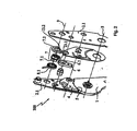
- FIG. 2 shows an inventive device 100 at least partially in an exploded view.
- the second fitting part 2 has two substantially identical second fitting part 2.1 components, which are arranged parallel to each other and between which the first fitting part 1, the Ven-astklinke 4, the latch plate 6 and the drive means 7 are arranged.
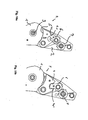
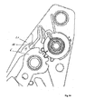
- FIG. 3 shows a further embodiment of a device 100 according to the invention, also a tilt adjuster for the back of a seat of a vehicle.
- the device 100 also has the first fitting part 1, the second fitting part 2, the latch 4 and the latch plate 6 on.
- the second fitting part 2 is rotatable relative to the first fitting part 1 about the rotation axis 3.
- the latching pawl 4 has the toothing 5 as a form-locking and / or force-locking means with which it is in engagement with the counter-toothing 5.1 of the first fitting part 1.
- the latching pawl 4 is secured by the latching plate 6 in the latching position R and is adjustable in the release position F, in which the device 100 is unlocked.
- the device 100 also has a drive means 7 with a securing segment 7.1 and a second segment 7.2 that is rotatable about the drive shaft 9.
- FIGS. 1 and 2 In contrast to the devices 100 according to the invention FIGS. 1 and 2 is the first form and / or adhesion means 7.11 - 7.1i of the fuse segment 7.1 a securing means 10 in the form of a hook, the non-positive and / or positive locking in the locking position R of the latch plate 6 with the front locking tooth 11 of the third form and / or adhesion means 6.1 of the latch plate 6 cooperates.
- the device 100 has a first power means 8.1 and a second power means 8.2, wherein the securing segment 7.1 is adjustable against the force of the first power means 8.1 and the second segment 7.2 against the force of the second power means 8.2. Both force means 8.1, 8.2 therefore hold the latch plate 6 in the latching position R.
- FIG. 4 shows the latch plate 6 in an enlarged section of the device 100 of FIG. 3 in the locking position R and the drive means 7 in de. Securing position S.
- the latching plate 6 Under the action of external forces acting, for example, on the latching pawl 4, the latching plate 6 can not open unintentionally, since the securing means 10 positively and / or non-positively cooperates with the locking tooth 11 and therefore blocks the adjustment of the latching plate 6.
- FIG. 5 shows the unlocking of the device 100 of Figures 3 and 4 , wherein the latching plate 6 is shown in the latching position R, R 'and in the release position F and wherein the drive means 7 is shown in the drive position A.
- a handle not shown, which generates via a spline shaft 12 of the drive means, which abuts the drive shaft 9, initiated torque, the securing means 10 is rotated against the force of the first force means 8.1, to the locking tooth 11 is no longer encompassed by the hook-like securing means 10. This is essentially no additional adjustment of the drive means 7, so essentially no additional idle required.
- the first and second force means are preferably springs.
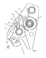
- FIG. 6 shows the device according to the invention with a drive means analogous to that of FIGS. 4 and 5 in an exploded view.
- This embodiment also comprises two substantially identical second fitting part components 2.1, which are arranged parallel to one another and between which the first fitting part 1, the latching pawl 4, the latching plate 6 and the drive means 7 are arranged.
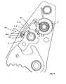
- FIG. 7 shows a further embodiment of a device 100 according to the invention.
- the securing segment 7.1 as a securing means 10, a link and an adjusting means 15, wherein the adjusting means 15 is a bolt which is adjustable along the link.
- the adjusting means 15 is also guided along a guide means 14 of the second fitting part 2.
- the guide means 14 is also a backdrop.
- the terms adjustment means 15 and bolt are used synonymously.
- the FIG. 7 shows the locking plate 6 in the locking position R and the securing segment 7.1 of the drive means 7 in the securing position S.
- the bolt 15 along a contour 16 of the front locking tooth 11 of the third form and / or adhesion means 6.1 of the latch plate 6 adjusted.
- the latching plate 6 is simultaneously adjusted by means of the second form and / or adhesion means 7.21 - 7.2i of the second segment 7.2.
- FIG. 8 shows the device 100 of the invention FIG. 7 ,
- the FIG. 8a shows the locked state of the device 100. If the drive means 7 is not adjusted, the latch plate 6 is by the bolt 15 in each locking position R. secured.
- the FIG. 8b shows a position of the securing segment 7.1 when adjusting the securing segment 7.1 of the securing position S in the drive position A. The latch plate 6 is still in the locking position R.
- the guide means 14 has a curvature, so that an adjustment of the bolt 15 is prevented due to a large load. The curvature is further provided so that the adjustment of the bolt 15 in the drive position A of the fuse segment 7.1 or in the release position F of the latch plate 6 is easy.
- FIG. 8c shows the fuse segment 7.1 in the drive position A.
- the latch plate 6 is in the release position F.
- the latch pawl 4, which is not shown here, or the device 100 is unlocked.
- FIG. 9 shows a further device 100 according to the invention with a securing means 10 with a link and a bolt 15 and a guide means 14 in the form of a backdrop.
- the guide means 14 has a curvature, or the latching plate 6 has a contour 16, through which an additional adjustment of the drive means 7, ie an idle, is required, before the securing segment 7.1 has reached the drive position A, in which the latching plate 6 of the locking position R in the release position F is adjustable.
- the latching segment is still in the safety position S.
- the latching plate 6 is in the latching position R.
- the circle K shows the engagement of the second positive and / or positive connection clamp 7.21 - 7.2i of the second segment 7.2 with the third mold and / or adhesion means in 6.1 of the latching plate 6.
- the second and third form and / or adhesion means 7.21 - 7.2i, 6.1 are not completely engaged with each other.
- FIGS. 7 to 9 can be integral with the drive means 7, so that the securing segment 7.1 and the second segment 7.2 - apart from the bolt 15 of the securing means 10 - are in one piece.
- the adjustment of the seat according to the requirements is therefore simple and inexpensive possible in the modular principle.
- FIG. 10 shows a device 100 according to the invention, however, without the blocking and the securing means.
- the device 100 is a recliner for adjusting the inclination of a backrest of a seat, which is not shown, with respect to the seat part of the seat, which is also not shown, wherein a first fitting part 1 on the seat part and a second fitting part 2 on the Lean back of the seat are arranged. Therefore, the first and the second fitting part 1, 2 on a common axis of rotation 3, so that by turning the second fitting part 2 about the rotation axis 3, the second fitting part 2 relative to the first fitting part 1 is adjustable.
- the device 100 has a latching pawl 4 with form and / or force-locking means 5, here a toothing, as well as a latching plate 6.
- the latching plate 6 acts in its latching position R (see. FIG. 10a ) positively and / or non-positively with the Verrastklinke 4, which in turn cooperates in a latching position R positive and / or non-positively with the counter-toothing of the first fitting part 1.
- the positive and / or frictional connection between the latching plate 6 and the latching pawl 4 takes place through an interaction of the surfaces 6.1 or 4.2.
- the latching pawl 4 is rotatably arranged on the second fitting part 2, so that both the second fitting part 2 and the latching pawl 4 must be locked in the latching position R relative to the first fitting part 1.
- the latching plate 6 is reversible from the latching position R (see. FIG. 10a ) in a counterclockwise direction to a release position F (see. FIG. 10b ) by means of a drive means 7 adjustable.
- the release position F the latching plate 4 cooperates with the latching pawl 6 in such a way that the latching plate 4 rotates in the clockwise direction.
- the latch plate 6 presses against the face 4.1 of the latching pawl and turns it clockwise.
- the latching pawl 4 no longer acts positively and / or non-positively with the first fitting part 1.
- the device 100 is therefore unlocked in the release position F.
- the device 100 In a heavy load on the locked seat, especially in an accident, the latch plate 6, for example, due to inertia, tries to turn counterclockwise, which can lead to unlocking the Verratklinke 4.
- the device 100 according to the invention has a blocking and a securing means, the function of which will be explained with reference to the following figures.
- FIG. 11 shows an embodiment of the device according to the invention in the locked and locked state in which an unwanted self-opening of the recliner is excluded.
- a blocking means in the present case arranged on the fitting 2 projection 2.1, on.
- a safety ball 10 is arranged between the projection 2.1 and the latching plate 6.
- This ball 10 is connected to the drive 7 with an elastically resilient connecting means 11, wherein the composite and / or the drive 7 are designed so that the connecting means 11 is only taken in the respective direction of rotation of the drive 7, if this mechanically or manually ; ie wanted, but not induced by a crash takes place.
- the drive 7 and the connecting means 11 are designed and coordinated so that the ball 10 is spent in a very specific position in the gap, in which there is still the smallest possible clearance between the ball and the adjacent contours 6.1 and 2.1.1 , Furthermore, the drive 7 is designed so that at its intended rotation in a clockwise direction, first the ball 10 is at least partially removed from the gap 12 before latch plate 6 begins to rotate. Furthermore, from the FIG. 11 It can be seen that the ball 10 is disposed between the contour 2.1.1 of the projection 2.1 and the contour 6.1 of the latching plate 6, wherein in normal operation between the contours and the ball 10 at least one side a certain game (not shown). This game allows the adjustment of the two plates 1, 2 to each other.
- the contour 6.1 is designed as a curve whose radius increases in a clockwise direction, so that the radius R "6.1 is greater than the radius R'6.1
- the ball 10 thus prevents the latch plate 6 automatically unintentionally rotated counterclockwise and thus the engagement of the surfaces 4.2 and 6.2 is repealed.
- FIG. 12 shows the device according to FIG. 11 in unlocked and unlocked state.
- the drive 7 was manually or mechanically; ie intentionally rotated in a clockwise direction, which can be recognized by means of the marking lines 13 'and 13 ", which, in contrast to the illustration according to FIG. 11 do not cover up anymore.
- the connecting means 11 was first taken and thus at first partially pulled out of the gap 12, the ball 10 at least partially. Slightly offset in time, the drive 7, the latch plate 6, as shown by the arrow, rotated counterclockwise and thus repealed the latching engagement between the surfaces 4.2 and 6.2.
- FIG. 13 shows the so-called “min-material position”, ie the position at which all tolerances accumulate in such a way that the gap 12 its maximum size reached.
- the ball 10 is positioned by the drive 7 or the connecting means 11 very deep into the gap 12, so that in the event of a crash, the latch plate 6 must perform only a very small rotation before the blocking function of the ball 10 occurs , This minimum free travel of the latch plate 6 causes no loss of strength of the recliner occurs.
- FIG. 14 is the so-called "max-material position” shown, ie the position at which the manufacturing tolerances add up so that the gap 12 is minimal in the context of manufacturing tolerances.
- the ball 10 is positioned by the drive 7 and the connecting means 11 to the upper end of the gap 12 and acts there blocking, without the functioning of the fuse is impaired. Otherwise, the comments on FIG. 4 directed.
- FIG. 15 shows essentially the device according to the FIGS. 11 to 14 ,
- the ball 10 has been replaced by a freewheeling element 10.2, which is rotatable only counterclockwise about the plane of rotation extending into the plane of the paper 10.1.
- the freewheel element has a spring means 10.3, the freewheel element biases in a clockwise direction.
- the connecting means 11 is not resilient, but substantially rigid, but equipped on the drive 7 with a swivel executed.
- the contours 6.1 and 2.1.1 are not equipped with a rising, but provided with a constant or to the output of the gap 12 decreasing slope contour.
- the freewheeling element is positioned by the drive 7 or by the connecting means 11 at a location in the gap 12 at which there is no play between the freewheeling element 10.2 and the contours 6.1 and 2.1.1.
- the displacement of the freewheeling element must be such that the freewheeling element is not blocked. Since the freewheeling element 10.2 in the present case is only rotatable counterclockwise in the present case, it prevents the rotation of the latching plate 6 in the clockwise direction in the event of a crash. Otherwise, the device works according to FIG. 15 analogous to the device according to the FIGS. 11-14 ,
- FIG. 16 Is the device according to FIG. 15 shown in the unlocked state.
- the freewheeling element 10.2 has been pulled by the drive 7 to the upper end of the gap 12, where it no longer acts locking on the latch plate 6, thus can also be rotated by the drive 7 counterclockwise, so that the latch plate 6 is no longer locking together with the latching pawl 4 acts.
- the displacement of the freewheeling element must be such that the freewheeling element is not blocked.
Landscapes
- Engineering & Computer Science (AREA)
- Aviation & Aerospace Engineering (AREA)
- Transportation (AREA)
- Mechanical Engineering (AREA)
- Chairs For Special Purposes, Such As Reclining Chairs (AREA)
- Seats For Vehicles (AREA)
- Lock And Its Accessories (AREA)
Abstract
Description
Die vorliegende Erfindung betrifft Vorrichtungen, insbesondere für einen Kraftfahrzeugsitz, mit der das Verstellen eines ersten Beschlagteils und eines zweiten Beschlagteils relativ zueinander verriegelbar und entriegelbar ist, mit einem Antriebmittel und einer Verrastplatte, wobei die Verrastplatte mittels dem Antriebmittel reversibel verstellbar ist, wobei die Verrastplatte das Verstellen der Beschläge relativ zueinander in einer Rastposition verriegelt und in einer Freigabeposition entriegelt. Weiterhin betrifft die vorliegende Erfindung eine Vorrichtung zum Verriegeln und zum Entriegeln, einen Sitz mit einer erfindungsgemäßen Vorrichtung sowie ein Verfahren zum Sichern einer Vorrichtung gegen Selbstöffnung.The present invention relates to devices, in particular for a motor vehicle seat, with which the adjustment of a first fitting part and a second fitting part is locked and unlocked relative to each other, with a drive means and a latching plate, wherein the latching plate is reversibly adjustable by means of the drive means, wherein the latching plate Adjusting the fittings locked relative to each other in a locking position and unlocked in a release position. Furthermore, the present invention relates to a device for locking and unlocking, a seat with a device according to the invention and a method for securing a device against self-opening.
Vorrichtungen zum Verriegeln und Entriegeln von Kraftfahrzeugsitzes müssen hohen Belastungen standhalten, um sich, insbesondere bei einem Unfall, nicht ungewollt zu öffnen und zu verstellen und damit eine zusätzliche Gefahr für die Insassen der Fahrzeuges darzustellen. Es hat sich beispielsweise gezeigt, dass Neigungsverstellvorrichtungen für Sitze im Gepäckrückhaltetest dazu tendieren, sich bei großer Belastung ungewollt zu öffnen. Es hat deshalb nicht an Versuchen gefehlt, Sicherungen zur Verfügung zu stellen, die eine derartige selbsttätige Öffnung verhindern. Beispielhaft wird die Druckschrift
Es war deshalb die Aufgabe der vorliegenden Erfindung, eine Vorrichtung zum Verriegelt und Entriegeln, insbesondere für ein Kraftfahrzeugsitz zur Verfügung zu stellen, die die Nachteile des Standes der Technik nicht aufweist.It was therefore an object of the present invention to provide a device for locking and unlocking, in particular for a motor vehicle seat, which does not have the disadvantages of the prior art.
Die Aufgabe wird gelöst mit einer Vorrichtung, insbesondere für einen Kraftfahrzeugsitz, mit der das Verstellen eines ersten Beschlagteils und eines zweiten Beschlagteils relativ zueinander verriegelbar und entriegelbar ist, mit einem Antriebmittel, einer Verrastplatte (6) und einer Verrastklinke (4), wobei die Verrastklinke (4) durch Verrasten mit dem ersten Beschlagteil (1) relativ zu diesem arretierbar ist, wobei die Verrastplatte mittels dem Antriebsmittel reversibel verstellbar ist, wobei die Verrastplatte das Verstellen der Verrastklinke in einer Rastposition verriegelt und in einer Freigabeposition entriegelt, wobei das Antriebmittel ein Sicherungssegment zum Sichern der Verrastplatte gegen Selbstöffnen aufweist.The object is achieved with a device, in particular for a motor vehicle seat, with which the adjustment of a first fitting part and a second fitting part relative to each other can be locked and unlocked, with a drive means, a latch plate (6) and a latching pawl (4), wherein the Verrastklinke (4) is lockable relative to this by latching with the first fitting part (1), wherein the latching plate is reversibly adjustable by means of the drive means, wherein the latching plate locks the Verrastklinke in a latching position and unlocked in a release position, wherein the drive means is a securing segment for securing the latch plate against self-opening.
Durch das zusätzliche Sicherungssegment des Antriebmittels wird die Verrastplatte gegen Selbstöffnen gesichert. Die Verrastplatte verbleibt daher bei großen Belastungen sicher in der Rastposition und verriegelt die Verrastklinke, so dass die Vorrichtung verriegelt ist.Due to the additional securing segment of the drive means the latch plate is secured against self-opening. The latch plate therefore remains safely at high loads in the locked position and locks the latch pawl, so that the device is locked.
Eine Rastposition im Sinne der Erfindung ist jede Position der Verrastplatte, in der die Verrastplatte die Verrastklinke verriegelt. Eine freigabeposition im Sinne der Erfindung ist jede Position der Verrastplatte, in der sie die Verrastklinke nicht verriegelt.A detent position according to the invention is any position of the latch plate in which the latch plate locks the latch pawl. A release position according to the invention is any position of the latch plate in which it does not lock the Verrastklinke.
Da die Vorrichtung bei großer Belastung sicher in der Rastposition verbleibt, ermöglicht das Vorhandensein des Sicherungssegmentes das Optimieren des Verriegelungswinkels-dahingehend, dass das Entriegeln leichter und daher für den Nutzer komfortabler möglich ist. Der durch das Sicherungssegment entstandene Freiraum kann für eine komfortorientierte Auslegung genutzt werden.Since the device remains safely in the locking position under heavy load, the presence of the securing segment makes it possible to optimize the locking angle-in that the unlocking is easier and therefore more comfortable for the user. The space created by the securing segment can be used for a comfort-oriented design.
Eine bevorzugte Ausführungsform, die die Aufgabe ebenfalls löst, ist eine Vorrichtung zum Verriegeln und zum Entriegeln, insbesondere eines Beschlages zum Versteifen von Teilen eines Sitzes, insbesondere eines Kraftfahrzeugsitzes, die ein erstes Beschlagteil, eine Verrastklinke und wenigstens eine Verrastplatte aufweist, wobei die Verrastklinke durch Verrasten mit dem ersten Beschlagteil relativ zu diesem arretierbar ist, wobei die Verrastplatte in eine das Verrasten sichernde Rastposition und in eine das Verrasten nicht sichernde Freigabeposition verstellbar ist, wobei die Vorrichtung ein Antriebmittel umfasst, das zumindest teilweise reversibel von einer Antriebposition in eine Sicherungsposition verstellbar ist, wobei das Verstellen der Verrastplatte von der Rastposition in die Freigabeposition nur in der Antriebposition möglich ist.A preferred embodiment, which also achieves the object, is a device for locking and unlocking, in particular a fitting for stiffening parts of a seat, in particular a motor vehicle seat, having a first fitting part, a latching pawl and at least one latching plate, wherein the latching pawl Locking with the first fitting part can be locked relative to this, wherein the latching plate is adjustable in a latching locking position and in a non-latching release position, wherein the device comprises a drive means, at least partially is reversibly adjustable from a drive position to a securing position, wherein the adjustment of the latching plate from the locking position to the release position only in the drive position is possible.
Das Antriebmittel muss zumindest teilweise in die Antriebposition verstellt werden, damit die Verrastplatte in die Freigabeposition verstellt werden kann. Solange das Antriebmittel nicht angetrieben wird, ist daher ein ungewolltes Verstellen der Verrastplatte, und daher ein Selbstöffnen der Vorrichtung, bei dem die Verrastplatte von der Rastposition in die Freigabeposition verstellt wird, nicht möglich. Auch in dieser Ausführungsform bleibt die Vorrichtung bei großen Belastungen in der Rastposition sicher verriegelt.The drive means must be at least partially adjusted in the drive position, so that the latch plate can be moved to the release position. As long as the drive means is not driven, therefore, an unintentional adjustment of the latch plate, and therefore a self-opening of the device in which the latch plate is moved from the latching position to the release position, not possible. Also in this embodiment, the device remains securely locked at high loads in the locking position.
Die folgenden Ausführungen gelten die oben genannten Ausführungen:The following versions apply the above mentioned versions:
Bevorzugt weist das Antriebmittel ein Sicherungssegment und ein zweites Segment auf. Die Verrastplatte ist daher entweder nur mittels dem zweiten Segment oder mittels dem zweiten Segment und dem Sicherungssegment gemeinsam von der Rastposition in die Freigabeposition und zurück verstellbar.The drive means preferably has a securing segment and a second segment. The latching plate is therefore either only by means of the second segment or by means of the second segment and the securing segment together from the locking position to the release position and back adjustable.
In einer bevorzugten Ausführungsform ist das Antriebmittel um eine Antriebachse drehbar, wobei das Sicherungssegment durch Drehen des Antriebmittels um die Antriebachse von der Sicherungsposition in die Antriebposition und die Verrastplatte durch Drehen des Antriebmittels um die Antriebachse von der Rastposition in die Freigabeposition und zurück verstellbar ist. Daher erfolgt der Antrieb des Sicherungssegmentes auf derselben Achse, wie der Antrieb der Verriegelung und Entriegelung der Vorrichtung. Es werden keine weiteren Bauteile zum Betätigen des Sicherungssegmentes benötigt.In a preferred embodiment, the drive means is rotatable about a drive axis, wherein the securing segment is adjustable by rotating the drive means about the drive axis from the securing position to the drive position and the latch plate by rotating the drive means about the drive axis from the latching position to the release position and back. Therefore, the drive of the fuse segment takes place on the same axis as the drive of the locking and unlocking of the device. There are no other components needed to operate the fuse segment.
Bevorzugt wird das Antriebmittel mittels einer Handhabe betätigt. Der Fachmann versteht, dass auch eine elektrische Betätigung möglich ist.Preferably, the drive means is actuated by means of a handle. The skilled person understands that an electrical operation is possible.
Bevorzugt ist das zweite Segment entgegen der Kraft eines zweiten Kraftmittels um die Antriebachse drehbar, so dass die Verrastplatte mittels der Kraft des zweiten Kraftmittels in der Rastposition gehalten wird.Preferably, the second segment is rotatable about the drive axis against the force of a second force means, so that the latch plate is held in the latching position by means of the force of the second force means.
Vorzugsweise weist das Sicherungssegment ein erstes Form- und/oder Kraftschlussmittel und das zweite Segment ein zweites Form- und/oder Kraftschlussmittel auf, wobei das erste sowie das zweite Form- und/oder Kraftschlussmittel zumindest teilweise mit einem dritten Form- und/oder Kraftschlussmittel der Verrastplatte in Eingriff sind. Durch den gegenseitigen Eingriff der Form- und/oder Kraftschlussmittel wirkt eine Belastung auf die Verrastplatte auch form- und/oder kraftschlüssig auf das Antriebmittel, insbesondere auf das Sicherungssegment.Preferably, the securing segment has a first positive and / or positive locking means and the second segment has a second positive and / or frictional means, wherein the first and the second positive and / or frictional means at least partially with a third positive and / or frictional means Locking plate are engaged. Due to the mutual engagement of the positive and / or positive locking means, a load on the latching plate also acts positively and / or non-positively on the drive means, in particular on the securing segment.
Bevorzugt ist das dritte Form- und/oder Kraftschlussmittel der Verrastplatte eine Verzahnung.Preferably, the third form and / or frictional engagement means of the latch plate is a toothing.
In einer bevorzugten Ausführungsform sind das erste Form- und/oder Kraftschlussmfttel sowie das zweite Form- und/oder Kraftschlussmittel jeweils zumindest zwei Zähne mit demselben Zahnabstand, wobei der Übergangszahnabstand zwischen dem vorderen Zahn des ersten Form- und/oder Kraftschlussmittels und dem hinteren Zahn des zweiten Form- und/oder Kraftschlussmittels, die aneinander angrenzen, ungleich dem Zahnabstand ist, bevorzugt größer. Der Übergangszahnabstand ist daher ein gewollter Teilungsfehler der Verzahnung des Antriebsmittel bzw. zwischen dem Sicherungssegment und dem zweiten Segment, der einen Leerlauf ermöglicht, durch den das Entriegeln der Vorrichtung sehr gleichmäßig möglich Ist, wenn die Entriegelung durch das Antriebmittel erfolgt. Dagegen führt der Übergangszahnabstand zwischen den Zähnen des Sicherungssegmentes und den Zähnen des zweiten Segmentes bei einer großen auf die Verrastplatte wirkenden Belastung, durch die diese zum Selbstöffnen tendiert, zu einer Kollision der Verzahnung der Verrastplatte mit der des Antriebmittels. Die Verrastplatte verstellt sich daher, insbesondere aufgrund von Toleranzen, geringfügig, wird dann jedoch durch die Kollision sicher gestoppt, so dass die Verrastplatte in der Rastposition verbleibt und die Vorrichtung weiterhin sicher verriegelt ist.In a preferred embodiment, the first form and / or Kraftschlussmfttel and the second form and / or adhesion means are each at least two teeth with the same tooth spacing, the transition tooth spacing between the front tooth of the first positive and / or frictional means and the rear tooth of second form and / or frictional means adjacent to each other, not equal to the tooth spacing, preferably larger. The transition tooth spacing is therefore a deliberate pitch error of the toothing of the drive means or between the securing segment and the second segment, which allows idling, by the unlocking of the device is very uniformly possible when the unlocking is done by the drive means. In contrast, the transition tooth spacing between the teeth of the securing segment and the teeth of the second segment leads to a collision of the toothing of the latching plate with that of the drive means in the case of a large load acting on the latching plate, which tends to self-open. The latch plate is therefore adjusted, in particular due to tolerances, slightly, but is then stopped safely by the collision, so that the latch plate remains in the latching position and the device is still securely locked.
Bevorzugt ist die Verrastplatte um eine Verrastachse drehbar. Der Leerlauf entspricht dann einem Drehwinkel der Verrastplatte von ca. 3 - 5°.The latching plate is preferably rotatable about a latching axis. The idle then corresponds to a rotation angle of the latch plate of about 3 - 5 °.
In einer weiteren bevorzugten Ausführungsform ist das erste Form- und/oder Kraftschlussmiftel ein Sicherungsmittel, das in der Rastposition in Eingriff mit einem vorderen Rastzahn des dritten Form- und/oder Kraftschlussmittels der Verrastplatte ist. Bei großer Belastung wird das Verstellen der Verrastplatte von der Rastposition in die Freigabeposition durch Zusammenwirken des Rastzahns mit dem Sicherungsmittel blockiert.In a further preferred embodiment, the first form and / or Kraftschlussmiftel is a securing means which is in the latching position in engagement with a front latching tooth of the third form and / or adhesion means of the latch plate. At high load, the adjustment of the latching plate is blocked by the locking position in the release position by interaction of the locking tooth with the securing means.
Der Fachmann versteht, dass der Rastzahn das Sicherungsmittel in der Rastposition bevorzugt hintergreift. In dieser Ausführungsform ist das Sicherungssegment vorzugsweise entgegen der Kraft eines ersten Kraftmittels um die Antriebachse drehbar, so dass das Sicherungssegment die Verrastplatte zusätzlich mittels der Kraft des ersten Kraftmittels in der Rastposition hält. Das erste Kraftmittel bewirkt, dass das Sicherungssegment bei Belastung, beispielsweise bei Fahrt des Fahrzeugs, in einer Position gehalten wird und nicht klappert.The skilled person understands that the locking tooth preferably engages behind the securing means in the latching position. In this embodiment, the securing segment is preferably rotatable about the drive axis counter to the force of a first force means, so that the securing segment additionally holds the latching plate in the latching position by means of the force of the first force means. The first force means causes the securing segment is held in a position under load, for example when driving the vehicle, and does not rattle.
Ebenfalls bevorzugt umfasst das Sicherungsmittel ein Verstellmittel, das in der Rastposition an einer Kontur des vorderen Rastzahns anliegt. In dieser Ausführungsform wird das Verstellmittel bei Antrieb des Sicherungssegmentes vor und/oder während des Verstellens der Verrastplatte verstellt, so dass es in der Antriebposition des Sicherungssegmentes die Verrastplatte nicht beim Verstellen behindert.Also preferably, the securing means comprises an adjusting means, which rests in the latching position on a contour of the front ratchet tooth. In this embodiment, the adjustment is adjusted when driving the fuse segment before and / or during the adjustment of the latch plate, so that it does not interfere with the Verrastplatte in the drive position of the fuse segment during adjustment.
Bei Antrieb des Antriebmittels wird das zweiten Segment gemeinsam mit dem Sicherungssegment verstellt, so dass das Sicherungsmittel den Rastzahn nicht behindert. Aufgrund von Toleranzen der Vorrichtung, beispielsweise aufgrund von Fertigungs- oder Herstellungstoleranzen, entsteht gegebenenfalls ein geringer Leerlauf beim Verstellen der Verrastplatte von der Rastposition in die Freigabeposition. Im wesentlichen ist das Verstellen jedoch ohne einen zusätzlichen Leerlauf möglich ist. Der Entriegelungswinkel ist daher im Gegensatz zur o. g. Ausführungsform, die einen bewussten zusätzlichen Leerlauf vorsieht, kleiner.When driving the drive means, the second segment is adjusted together with the securing segment, so that the securing means does not hinder the locking tooth. Due to tolerances of the device, for example, due to manufacturing or manufacturing tolerances, optionally creates a low idle when adjusting the latch plate from the locking position to the release position. Essentially, however, the adjustment is possible without an additional idle. The unlocking angle is therefore in contrast to the o. G. Embodiment providing deliberate additional idle, smaller.
Die folgenden Ausführungen gelten für alle oben beschriebenen Ausführungsformen der Erfindung.The following statements apply to all embodiments of the invention described above.
Vorzugsweise weist das Sicherungssegment zumindest einen Anschlag und das zweite Segment zumindest einen Gegenanschlag auf, so dass beim Verstellen des Antriebsmittels das zweite Segment vom Sicherungssegment mitverstellt wird.Preferably, the securing segment has at least one stop and the second segment has at least one counter-stop, so that when adjusting the drive means, the second segment is also adjusted by the securing segment.
Bevorzugt weist das Antriebmittel ein Keilwellenprofil auf, das an der Antriebachse anliegt, so dass das zweites Segment beim Drehen der Antriebachse nicht verrutscht.Preferably, the drive means has a splined shaft profile which bears against the drive axle, so that the second segment does not slip when the drive axle is rotated.
Weitere vorteilhafte Ausgestaltungen der Erfindung sind in den Unteransprüchen beschrieben.Further advantageous embodiments of the invention are described in the subclaims.
Das Aufteilen des Antriebmittels in das Sicherungssegment und das zweite Segment ermöglicht eine erheblich größere Sicherheit gegen Selbstöffnen bei einem Unfall. Die Vorrichtung ist leichter entriegelbar. Der zusätzliche Bauteileaufwand beschränkt sich auf ein oder zwei Bauteile und ist daher sehr gering. Das Antriebmittel ist durch "Zusammenstecken" schnell und einfach montierbar. Die zusätzlichen Herstellungs-und Montagekosten sind daher gering.The splitting of the drive means in the securing segment and the second segment allows a considerably greater security against self-opening in the event of an accident. The device is easier unlocked. The additional component cost is limited to one or two components and is therefore very low. The drive means can be quickly and easily assembled by "plugging together". The additional manufacturing and assembly costs are therefore low.
Ein weiterer Gegenstand der vorliegenden Erfindung ist eine Vorrichtung, insbesondere für einen Kraftfahrzeugsitz, mit der das Verstellen eines ersten Beschlagteils und eines zweiten Beschlagteils relativ zueinander verriegelbar und entriegelbar ist, mit einem Antriebmittel, einer Verrastplatte und einer Verrastklinke, wobei die Verrastklinke durch Verrasten mit dem ersten Beschlagteil relativ zu diesem arretierbar ist, wobei die Verrastplatte mittels dem Antriebmittel reversibel verstellbar ist und die Verrastplatte das Verstellen der Verrastklinke in einer Rastposition verriegelt sowie in einer Freigabeposition entriegelt, bei der zwischen die Außenkontur der Verrastplatte und einem Blockierungsmittel, das an dem zweiten Beschlagteil angeordnet ist, ein Sicherungsmittel anbringbar ist.Another object of the present invention is a device, in particular for a motor vehicle seat, with which the adjustment of a first fitting part and a second fitting part relative to each other is lockable and unlockable, with a drive means, a latch plate and a latch pawl, wherein the Verrastklinke by latching with the the first fitting part can be locked relative thereto, wherein the latching plate is reversibly adjustable by means of the drive means and the latching plate locks the Verrastklinke in a latching position and unlocked in a release position, in which between the outer contour of the latching plate and a blocking means, on the second fitting part is arranged, a securing means is attachable.
Es war für den Fachmann überaus erstaunlich und nicht zu erwarten, dass es mit der erfindungsgemäßen Vorrichtung gelingt, ein selbsttätiges Entriegeln der Verrastklinke sicher zu verhindern. Die erfindungsgemäße Vorrichtung ist einfach und kostengünstig herzustellen und zu montieren. Selbst bei vergleichsweise großen Fertigungstoleranzen ist die erfindungsgemäße Vorrichtung funktionsfähig. Das Blockiermittel ist vorzugsweise als mitfahrende Barriere ausgeführt, so dass es mit der erfindungsgemäßen Vorrichtung möglich ist Toleranzen auszugleichen und kein Verlust an Festigkeit auftritt.It was extremely surprising for the person skilled in the art and it was not to be expected that the device according to the invention succeeds in reliably preventing an automatic unlocking of the latching pawl. The device according to the invention is simple and inexpensive to manufacture and assemble. Even at comparatively large Manufacturing tolerances, the device of the invention is functional. The blocking agent is preferably designed as a moving barrier, so that it is possible with the device according to the invention to compensate for tolerances and no loss of strength occurs.
Erfindungsgemäß weist die Vorrichtung ein Sicherungsmittel auf, dass zur Sicherung zwischen der Verrastplatte und dem Blockierungsmittel angeordnet ist. Vorzugsweise ist dieses Sicherungsmittel mit dem Antriebsmittel, das die Rastplatte in die Rastposition bzw. in die Freigabeposition bewegt, verbunden. Dadurch kann gleichzeitig mit der jeweiligen Verstellung der Rastplatte das Sicherungsmittel entweder angebracht oder entfernt werden.According to the invention, the device has a securing means which is arranged for securing between the latching plate and the blocking means. Preferably, this securing means is connected to the drive means which moves the detent plate into the detent position or into the release position. As a result, the securing means can either be attached or removed simultaneously with the respective adjustment of the detent plate.
Bei dem Sicherungsmittel kann es sich um jedes dem Fachmann geläufige Sicherungsmittel handeln. Vorzugsweise handelt es sich bei dem Sicherungsmittel jedoch um eine Kugel, einen Zylinder oder um ein Sicherungsmittel, das nur in eine Richtung drehbar gelagert ist.The securing means may be any securing means known to those skilled in the art. Preferably, however, the securing means is a ball, a cylinder or a securing means which is rotatably mounted only in one direction.
Vorzugsweise ist zwischen der Verrastplatte, dem Blockierungsmittel und dem Sicherungsmittel ein gewisses Spiel vorhanden, das erstbei einer Überlast, beispielweise einem Crash, eliminiert wird. Diese Ausführungsform der vorliegenden Erfindung hat den Vorteil, dass die erfindungsgemäße Vorrichtung unter Normalbedingungen mit einem vergleichsweise geringen Kraftaufwand bedienbar ist.Preferably, there is a certain amount of play between the latch plate, the blocking means and the securing means which is eliminated only in the event of an overload, for example a crash. This embodiment of the present invention has the advantage that the device according to the invention can be operated under normal conditions with a comparatively small expenditure of force.
Die Aufgabe wird ebenfalls gelöst mit einem Sitz, der eine erfindungsgemäße Vorrichtung aufweist. Die Sicherheit, das sich die Vorrichtung des Sitzes nicht ungewollt löst, insbesondere bei einem Unfall, ist erheblich verbessert. Beispielsweise bei Verwendung der Vorrichtung zum Verriegeln und Entriegeln der Neigung der Lehne gegenüber dem Sitzteil eines Sitzes in einem Kraftfahrzeug löst sich auch bei Belastung der Lehne, beispielsweise durch in den Fahrgastraum geschleudertes Gepäck bei einem Unfall, die Neigungsverstellung nicht. Für den Insassen bietet der erfindungsgemäße Sitz daher eine größere Sicherheit. Außerdem ist der Sitz leichter entriegelbar.The object is also achieved with a seat having a device according to the invention. The safety that the device of the seat does not unintentionally solve, especially in an accident, is significantly improved. For example, when using the device for locking and unlocking the backrest relative to the seat part of a seat in a motor vehicle, the inclination adjustment does not dissolve even when the backrest is loaded, for example by luggage thrown into the passenger compartment in the event of an accident. For the occupant of the seat according to the invention therefore provides greater security. In addition, the seat is easier unlocked.
Ein weiterer Gegenstand der vorliegenden Erfindung ist ein Verfahren zum Entriegeln einer Vorrichtung zum Verriegeln und Entriegeln, wobei die Vorrichtung ein Antriebmittel mit einem Sicherungssegment und einem zweiten Segment, eine Verrastplatte sowie eine Verrastklinke aufweist, wobei das Sicherungssegment von einer Sicherungsposition in eine Antriebposition verstellt wird, bevor und/oder während die Verrastplatte mittels dem Antriebmittel von der Rastposition, in der in der sie das Verstellen der Verrastklinke (4) verriegelt, so dass die Vorrichtung verriegelt ist, in eine Freigabeposition, in der sie das Verstellen der Verrastklinke (4) nicht verriegelt, so dass die Vorrichtung entriegelt ist, verstellt wird. Durch Aufteilen des Antriebmittels in ein Sicherungssegment und ein zweites Segment ist auf sehr kostengünstige Weise ein Entriegelungsablauf realisierbar, der sehr leicht betätigbar ist. Solange das Antriebmittel, insbesondere das Sicherungssegment, nicht verstellt wird, ist die Verrastplatte in der Rastposition gesichert und die Vorrichtung verriegelt.A further subject of the present invention is a method for unlocking a device for locking and unlocking, the device having a drive means with a securing segment and a second segment, a latching plate and a latching pawl, wherein the securing segment is moved from a securing position into a drive position, before and / or while the latch plate by means of the drive means from the detent position in which it locks the adjustment of the Verrastklinke (4) so that the device is locked in a release position in which they do not adjust the Verrastklinke (4) locked, so that the device is unlocked, is adjusted. By dividing the drive means into a securing segment and a second segment, an unlocking procedure can be realized in a very cost-effective manner, which can be actuated very easily. As long as the drive means, in particular the securing segment, is not adjusted, the latching plate is secured in the latching position and the device is locked.
Im folgenden wird die Erfindung anhand der
-
Figur 1 - zeigt eine Ausführungsform einer erfindungsgemäßen Vorrichtung.
-
Figur 2 - zeigt eine erfindungsgemäße Vorrichtung zumindest teilweise in einer Explosionsdarstellung.
-
Figur 3 - zeigt eine weitere Ausführungsform einer erfindungsgemäßen Vorrichtung.
-
Figur 4 - zeigt die Verrastplatte in einem vergrößerten Ausschnitt der Vorrichtung der
Figur 3 in der Rastposition sowie das Antriebmittel in der Sicherungsposition. -
Figur 5 - zeigt das Entriegeln der Vorrichtung der
Figuren 3 und4 , wobei die Verrastplatte in der Rastposition und in der Freigabeposition dargestellt ist und wobei das Antriebmittel in der Antriebposition dargestellt ist. -
Figur 6 - zeigt eine erfindungsgemäße Vorrichtung in einer Explosionsdarstellung.
-
Figur 7 - zeigt eine weitere Ausführungsform einer erfindungsgemäßen Vorrichtung.
- Figur 8
- zeigt die erfindungsgemäße Vorrichtung der
Figur 7 -
Figur 9 - zeigt eine weitere erfindungsgemäße Vorrichtung.
-
Figur 10 - zeigt die erfindungsgemäße Vorrichtung jedoch ohne das Blockier- und das Sicherungsmittel.
-
Figur 11 - zeigt eine Ausführungsform der erfindungsgemäßen Vorrichtung im blockierten Zustand,
-
Figur 12 - zeigt die
Vorrichtung gemäß Figur 11 im entriegelten Zustand, -
Figur 13 - zeigt die
Vorrichtung gemäß Figur 11 bei maximalem Spiel, -
Figur 14 - zeigt die
Vorrichtung gemäß Figur 11 bei minimalem Spiel, -
Figur 15 - zeigt eine weitere Ausführungsform der erfindungsgemäßen Vorrichtung im blockierten Zustand und
-
Figur 16 - zeigt die
Vorrichtung gemäß Figur 15 im entriegelten Zustand.
- FIG. 1
- shows an embodiment of a device according to the invention.
- FIG. 2
- shows an inventive device at least partially in an exploded view.
- FIG. 3
- shows a further embodiment of a device according to the invention.
- FIG. 4
- shows the latch plate in an enlarged section of the device of
FIG. 3 in the locking position and the drive means in the securing position. - FIG. 5
- shows the unlocking of the device of
Figures 3 and4 Wherein the Verrastplatte is shown in the locking position and in the release position and wherein the drive means is shown in the drive position. - FIG. 6
- shows an inventive device in an exploded view.
- FIG. 7
- shows a further embodiment of a device according to the invention.
- FIG. 8
- shows the device of the invention the
FIG. 7 , - FIG. 9
- shows a further device according to the invention.
- FIG. 10
- shows the device according to the invention, however, without the blocking and securing means.
- FIG. 11
- shows an embodiment of the device according to the invention in the blocked state,
- FIG. 12
- shows the device according to
FIG. 11 in the unlocked state, - FIG. 13
- shows the device according to
FIG. 11 at maximum play, - FIG. 14
- shows the device according to
FIG. 11 with minimal play, - FIG. 15
- shows a further embodiment of the device according to the invention in the blocked state and
- FIG. 16
- shows the device according to
FIG. 15 in the unlocked state.
Das Antriebmittel 7 ist drehbar um eine Antriebachse 9 angeordnet und mit einer nicht dargestellten Handhabe verbunden.The drive means 7 is rotatably arranged about a
Zum gewollten Verstellen der Verrastplatte 6 von der Rastposition R in die Freigabeposition F wird das Antriebmittel 7 um die Antriebachse 9 von derFor intentional adjustment of the
Sicherungsposition S in eine Antriebposition A gedreht, und zwar bevorzugt gegen die Kraft eines ersten Kraftmittels 8.1, vorzugsweise einer Feder. Dabei wird der Übergangszahnabstand 7.01 zwischen dem vorderen Zahn 7.11 des Sicherungssegment 7.1 und dem hinteren Zahn 7.22 des zweiten Segmentes 7.2 verringert, bis er in der Antriebposition A im wesentlichen gleich dem Zahnabstand 7.00 des ersten und des zweiten Form- und/oder Kraftschlussmittels 7.11 - 7.1i, 7.21 - 7.2i ist, so dass der Zahnabstand 7.00 sowie der Übergangszahnabstand 7.01 am Antriebsmittel 7 gleichmäßig ist. Bevorzugt beträgt der benötigte Drehwinkel, um den das Antriebmittel 7 von der Sicherungsposition S in die Antriebposition A gedreht wird, ca. 3 - 5°. Danach werden das Sicherungssegment 7.1 und das zweite Segment 7.2 im wesentlichen synchron gedreht. Dafür weisen das Sicherungssegment 7.1 einen Anschlag 13.1 und das zweite Segment 7.2 einen Gegenanschlag 13.2 auf, die in der Antriebposition A aneinander anliegen, so dass das zweite Segment 7.2 beim Weiterdrehen mitgenommen wird. Die Verrastplatte 6 weist dritte Form- und/oder Kraftschlussmittel 6.1 auf, hier eine Teilverzahnung, die zumindest teilweise in Eingriff mit dem ersten und/oder zweiten Kraftschlussmittel 7.11 - 7.1i, 7.21 - 7.2i sind und beim Drehen des Antriebmittels 7 mit diesen zusammenwirken, so dass die Verrastplatte 6 von der Rastposition R in die Freigabeposition F verstellt wird.Fastened position S in a drive position A, preferably against the force of a first power means 8.1, preferably a spring. The transition tooth spacing 7.01 between the front tooth 7.11 of the securing segment 7.1 and the rear tooth 7.22 of the second segment 7.2 is reduced until it is substantially equal to the tooth spacing 7.00 of the first and second form and / or adhesion means 7.11 - 7.1 in the drive position A. i, 7.21 - 7.2i, so that the tooth spacing 7.00 and the transition tooth spacing 7.01 on the drive means 7 is uniform. Preferably, the required angle of rotation by which the drive means 7 is rotated from the securing position S to the drive position A, about 3 - 5 °. Thereafter, the fuse segment 7.1 and the second segment 7.2 are rotated substantially synchronously. For this purpose, the securing segment 7.1 a stop 13.1 and the second segment 7.2 on a counter-stop 13.2, which abut each other in the drive position A, so that the second segment is taken 7.2 on further rotation. The latching
Die
- Figur 1a zeigt:
- Sicherungssegment 7.1 in der Sicherungsposition S,
Verrastplatte 6 in der Rastposition R, ->die Vorrichtung 100 ist verriegelt. - Figur 1b zeigt:
- Sicherungssegment 7.1 in der Antriebposition A,
Verrastplatte 6 in der Rastposition R, ->die Vorrichtung 100 ist verriegelt. - Figur 1c zeigt:
- Sicherungssegment 7.1 in der Antriebposition A,
Verrastplatte 6 in der Freigabeposition F, ->die Vorrichtung 100 ist entriegelt.
- FIG. 1a shows:
- Securing segment 7.1 in the securing position S,
latch plate 6 in the locking position R, -> thedevice 100 is locked. - FIG. 1b shows:
- Securing segment 7.1 in the drive position A,
latch plate 6 in the latching position R, -> thedevice 100 is locked. - FIG. 1c shows:
- Securing segment 7.1 in the drive position A,
latch plate 6 in the release position F, -> thedevice 100 is unlocked.
Bei starker Belastung auf den verriegelten Sitz, insbesondere bei einem Unfall, versucht die Verrastplatte 6 ihrerseits, beispielsweise aufgrund von Massenträgheit, das Antriebrad 7 entgegen der Kraft des Kraftmittels 9 in Richtung zur Freigabeposition F zu verstellen, s.
Die Zähne 7.11, 7.12, 7.21, 7.22 des Antriebmittels 7 können daher zwar die Verrastplatte 6 antreiben, ein ungewolltes Lösen der Verrastplatte 6 wird jedoch durch Sperren der Drehmomentübertragung zwischen der Verrastplatte 6 und dem Antriebmittel 7 verhindert. Die Verrastplatte 6 wird dabei zwar gegebenenfalls geringfügig von der Rastposition R aus in Richtung zur Freigabeposition F verstellt, die Rastposition R bleibt aber soweit erhalten, dass die Verrastung gesichert und die Vorrichtung verriegelt ist.
- Figur 1d zeigt:
- Sicherungssegment 7.1 in der Sicherungsposition S,
Verrastplatte 6 in der Rastposition R bei starker Belastung, ->die Vorrichtung 100 ist verriegelt.
- FIG. 1d shows:
- Securing segment 7.1 in the securing position S, latching
plate 6 in the locking position R under heavy load, -> Thedevice 100 is locked.
Gegenüber herkömmlichen Vorrichtungen weist die erfindungsgemäße Vorrichtung 100 daher eine erhöhte Sicherheit gegenüber Selbstöffnung bei großer Belastung, insbesondere bei eine Unfall, auf.Compared to conventional devices, the
Im Gegensatz zu den erfindungsgemäßen Vorrichtungen 100 der
In den Ausführungsformen der Vorrichtung der
Eine herkömmliche Vorrichtung 100 mit einem Antriebmittel, das kein Sicherungssegment 7.1 aufweist, ist an die Anforderungen eines Sitzes anpassbar, lediglich indem das Antriebmittel 7 durch ein erfindungsgemäßes Antriebmittel 7 mit einem Sicherungssegment 7.1 und einem zweiten Segment 7.2 ersetzt wird. Das Anpassen des Sitzes gemäß den Anforderungen ist daher im Baukastenprinzip einfach und kostengünstig möglich.A
Bei einer starken Belastung auf den verriegelten Sitz, insbesondere bei einem Unfall, versucht sich die Verrastplatte 6, beispielsweise aufgrund von Massenträgheit, gegen den Uhrzeigersinn zu verdrehen, was zu einer Entriegelung der Verratklinke 4 führen kann. Um dies zu Verhindern weist die erfindungsgemäße Vorrichtung 100 ein Blockier- und ein Sicherungsmittel auf, deren Funktion anhand der folgenden Figuren erläutert wird.In a heavy load on the locked seat, especially in an accident, the
Anhand der
In
- 100100
- Vorrichtungcontraption
- 11
- Erstes BeschlagteilFirst fitting part
- 22
- Zweites BeschlagteilSecond fitting part
- 2.12.1
- Zweite Beschlagteilkomponente, Blockierungsmittel, VorsprungSecond fitting component, blocking agent, projection
- 2.1.12.1.1
- Kontur des BlockierungsmittelContour of the blocking agent
- 33
- Drehachseaxis of rotation
- 44
- Verrastklinkelatching pawl
- 4.24.2
- Anlageflächecontact surface
- 55
- Form- und/oder Kraftschlussmittel der Verrastklinke, VerzahnungForm and / or adhesion means of Verrastklinke, toothing
- 5.15.1
- Gegenverzahnungcounter teeth
- 66
- VerrastplatteVerrastplatte
- 6.16.1
- Drittes Form- und/oder Kraftschlussmittel, KonturThird form and / or adhesion means, contour
- 6.26.2
- Anlageflächecontact surface
- FF
- Freigabeposition der VerrastplatteRelease position of the latch plate
- RR
- Rastposition der VerrastplatteDetent position of the latch plate
- R'6.1R'6.1
- Radius der Kontur 6.1Radius of the contour 6.1
- R"6.1R "6.1
- Radius der Kontur 6.1 AntriebmittelRadius of the contour 6.1 Drive means
- 7.17.1
- Sicherungssegmentsecuring segment
- 7.11 - 7.1 i7.11 - 7.1 i
- Erstes Form- und/oder KraftschlussmittelFirst form and / or adhesion means
- 7.117.11
- Vorderer Zahn des ersten Form- und/oder KraftschlussmittelsFront tooth of the first form and / or adhesion means
- 7.27.2
- Zweites SegmentSecond segment
- 7.21 - 7.2i7.21 - 7.2i
- Zweites Form- und/oder KraflschlussmittelSecond form and / or Kraflschlussmittel
- 7.227.22
- Hinterer Zahn des zweiten Form- und/oder KraftschlussmittelsRear tooth of the second form and / or adhesion means
- 7.007:00
- Zahnabstandtooth pitch
- 7.017:01
- ÜbergangszahnabstandTransitional tooth spacing
- AA
- Antriebposition des Sicherungssegmentes des AntriebmittelsDrive position of the fuse segment of the drive means
- SS
- Sicherungsposition des Sicherungssegmentes des AntriebmittelsSecuring position of the securing segment of the drive means
- 8.18.1
- Erstes KraftmittelFirst force
- 8.28.2
- Zweites KraftmittelSecond force
- 99
- Antriebachsedrive axle
- 1010
- Sicherungsmittel, KugelSecuring means, ball
- 10.110.1
- Drehachseaxis of rotation
- 10.210.2
- FreilaufelementFreewheeling element
- 10.310.3
- Federmittelspring means
- 1111
- Vorderer Rastzahn des dritten Form- und/oder Kraftschlussmfttels, VerbindungsmittelFront ratchet teeth of the third form and / or frictional connection, connecting means
- 1212
- Keilwellenprofil, SpaltSplined shaft profile, gap
- 13.113.1
- Anschlag des SicherungssegmentesStop of the safety segment
- 13.213.2
- Gegenanschlag des zweiten SegmentesCounter-attack of the second segment
- 1414
- Führungsmittelguide means
- 1515
- Verstellmitteladjustment
- 1616
- Kontur des vorderen Rastzahns der dritten Form- und/oder KraftschlussmittelContour of the front ratchet teeth of the third form and / or adhesion means
Claims (22)
Applications Claiming Priority (3)
| Application Number | Priority Date | Filing Date | Title |
|---|---|---|---|
| DE200510030050 DE102005030050B3 (en) | 2005-06-27 | 2005-06-27 | Device e.g. for motor vehicle seat has latching plate, which can be reversibly adjusted with the aid of drive means whereby drive means has a safety segment for protecting latching plate against self-opening |
| DE102005037832A DE102005037832B4 (en) | 2005-02-25 | 2005-08-08 | Device for locking and unlocking with a safeguard against self-opening |
| EP06776085.0A EP1899194B1 (en) | 2005-06-27 | 2006-06-27 | Locking and releasing mechanism comprising a safety catch to prevent self-opening |
Related Parent Applications (2)
| Application Number | Title | Priority Date | Filing Date |
|---|---|---|---|
| EP06776085.0A Division-Into EP1899194B1 (en) | 2005-06-27 | 2006-06-27 | Locking and releasing mechanism comprising a safety catch to prevent self-opening |
| EP06776085.0 Division | 2006-06-27 |
Publications (2)
| Publication Number | Publication Date |
|---|---|
| EP2351663A2 true EP2351663A2 (en) | 2011-08-03 |
| EP2351663A3 EP2351663A3 (en) | 2011-12-28 |
Family
ID=37074252
Family Applications (3)
| Application Number | Title | Priority Date | Filing Date |
|---|---|---|---|
| EP11002173.0A Not-in-force EP2374655B1 (en) | 2005-06-27 | 2006-06-27 | Device for locking and unlocking with a means of preventing self-opening |
| EP11002172A Withdrawn EP2351663A3 (en) | 2005-06-27 | 2006-06-27 | Locking and releasing mechanism comprising a safety means to prevent self-opening |
| EP06776085.0A Not-in-force EP1899194B1 (en) | 2005-06-27 | 2006-06-27 | Locking and releasing mechanism comprising a safety catch to prevent self-opening |
Family Applications Before (1)
| Application Number | Title | Priority Date | Filing Date |
|---|---|---|---|
| EP11002173.0A Not-in-force EP2374655B1 (en) | 2005-06-27 | 2006-06-27 | Device for locking and unlocking with a means of preventing self-opening |
Family Applications After (1)
| Application Number | Title | Priority Date | Filing Date |
|---|---|---|---|
| EP06776085.0A Not-in-force EP1899194B1 (en) | 2005-06-27 | 2006-06-27 | Locking and releasing mechanism comprising a safety catch to prevent self-opening |
Country Status (6)
| Country | Link |
|---|---|
| US (2) | US8070231B2 (en) |
| EP (3) | EP2374655B1 (en) |
| JP (1) | JP5033796B2 (en) |
| KR (1) | KR101274375B1 (en) |
| CN (1) | CN101228044B (en) |
| WO (1) | WO2007000307A2 (en) |
Cited By (1)
| Publication number | Priority date | Publication date | Assignee | Title |
|---|---|---|---|---|
| DE102012008702A1 (en) * | 2012-04-28 | 2013-10-31 | Faurecia Autositze Gmbh | Adjustment device for a vehicle seat |
Families Citing this family (25)
| Publication number | Priority date | Publication date | Assignee | Title |
|---|---|---|---|---|
| DE102007042604B4 (en) * | 2006-11-17 | 2014-09-25 | Johnson Controls Gmbh | Vehicle seat with a tilt adjuster with free-pivoting functionality |
| EP2144783A1 (en) * | 2007-03-09 | 2010-01-20 | Johnson Controls GmbH | Vehicle seat with a tumbling recliner |
| US8783775B2 (en) * | 2008-10-23 | 2014-07-22 | Johnson Controls Technology Company | Locking device, especially for an adjustment fitting and especially for a vehicle seat, and vehicle seat |
| DE102008052893B4 (en) * | 2008-10-23 | 2016-03-24 | Johnson Controls Gmbh | Locking device, in particular for an adjustment fitting and in particular for a vehicle seat, and vehicle seat |
| DE102009032904A1 (en) * | 2009-05-12 | 2010-11-25 | Johnson Controls Gmbh | Device for locking and unlocking a first fitting part and a second fitting part, in particular a motor vehicle seat, relative to each other |
| JP5597013B2 (en) * | 2010-04-01 | 2014-10-01 | テイ・エス テック株式会社 | Car seat double-sided reclining lock device |
| DE102010019697B4 (en) * | 2010-05-05 | 2013-10-17 | Keiper Gmbh & Co. Kg | Fitting for a vehicle seat and vehicle seat |
| US9056563B2 (en) * | 2011-03-11 | 2015-06-16 | Johnson Controls Gmbh | Adjustment means for a vehicle seat |
| DE102011106284B4 (en) * | 2011-07-01 | 2022-10-20 | Keiper Seating Mechanisms Co., Ltd. | Fitting system for a vehicle seat and vehicle seat |
| DE102011052059B4 (en) * | 2011-07-22 | 2021-07-22 | Adient Luxembourg Holding S.À R.L. | Seat fitting for a motor vehicle seat |
| IN2014DN08535A (en) | 2012-05-07 | 2015-05-15 | Johnson Controls Tech Co | |
| DE102012013208B4 (en) * | 2012-05-07 | 2019-07-25 | Adient Luxembourg Holding S.À R.L. | Seat part of a vehicle seat |
| JP5865518B2 (en) * | 2012-06-26 | 2016-02-17 | ジョンソン コントロールズ コンポーネンツ ゲーエムベーハー ウントコンパニー カーゲー | Fitting for vehicle seat and vehicle seat |
| US9249827B2 (en) * | 2012-12-21 | 2016-02-02 | Taco Metals, Inc. | Hinge employing a ratchet for an upholstery seat |
| US8875347B2 (en) * | 2012-12-21 | 2014-11-04 | Taco Metals; Inc. | Hinge employing a ratchet for an upholstery seat |
| FR3004393B1 (en) * | 2013-04-12 | 2016-09-09 | Faurecia Sieges Automobile | PIVOTING BRAKE MECHANISM FOR A VEHICLE SEAT AND SEAT COMPRISING SUCH A MECHANISM |
| KR101395927B1 (en) * | 2013-05-28 | 2014-05-19 | 현대자동차주식회사 | Structure for movement prevention of gearshift-lever when rear-end collision occurs |
| DE102014111923B4 (en) * | 2014-08-20 | 2017-03-30 | Volkswagen Aktiengesellschaft | Armrest with crash protection |
| CN106314220A (en) * | 2015-06-17 | 2017-01-11 | 上汽通用五菱汽车股份有限公司 | Automobile seat folding mechanism |
| JP6809161B2 (en) * | 2016-11-21 | 2021-01-06 | トヨタ紡織株式会社 | Vehicle seat |
| DE102017204703A1 (en) | 2017-03-21 | 2018-09-27 | Brose Fahrzeugteile Gmbh & Co. Kg, Coburg | Vehicle seat with fitting arrangement and locking device on different longitudinal sides |
| CN108016338A (en) * | 2017-11-29 | 2018-05-11 | 延锋安道拓座椅有限公司 | A kind of switching mechanism |
| SE544527C2 (en) | 2019-01-18 | 2022-07-05 | Flokk Ab | A tilt locking device for a chair seat |
| CN113771932A (en) * | 2021-07-22 | 2021-12-10 | 浙江翱力新材料科技有限公司 | A heavy-duty truck |
| KR20240076911A (en) * | 2022-11-24 | 2024-05-31 | 현대자동차주식회사 | Device for manually folding seatback of electrically powered seat |
Citations (1)
| Publication number | Priority date | Publication date | Assignee | Title |
|---|---|---|---|---|
| DE10048127A1 (en) | 2000-09-28 | 2002-04-18 | Keiper Gmbh & Co | Car seat mounting allowing back rest to recline has pawl pivoted on first part cooperating with teeth on second part to lock components in place, eccentric which holds pawl in locked position pivoting against locking component in crash |
Family Cites Families (12)
| Publication number | Priority date | Publication date | Assignee | Title |
|---|---|---|---|---|
| US3779655A (en) * | 1971-12-23 | 1973-12-18 | Sanshin Kinzoku Ind Co Ltd | Angle variable joint for foldable chair |
| DE2931915A1 (en) * | 1979-08-07 | 1981-02-26 | Keiper Automobiltechnik Gmbh | JOINT FITTING FOR SEATS WITH ADJUSTABLE BACKREST, ESPECIALLY FOR MOTOR VEHICLE SEATS |
| US5310247A (en) * | 1992-03-23 | 1994-05-10 | Araco K.K. | Vehicle seats |
| DE19633782C1 (en) * | 1996-08-22 | 1998-03-26 | Keiper Recaro Gmbh Co | Locking fitting for motor vehicle seat |
| DE19654395C1 (en) * | 1996-12-27 | 1998-02-12 | Faure Bertrand Sitztech Gmbh | Cam for releasable locking of vehicle seat |
| WO2001062540A1 (en) * | 2000-02-25 | 2001-08-30 | Volkswagen Ag | Device for adjusting backrests of vehicle seats, especially motor vehicle seats |
| US6502903B2 (en) * | 2001-01-11 | 2003-01-07 | Bae Industries, Inc. | Seat integrated latch recliner assembly with inertial locking mechanism |
| US6644746B2 (en) * | 2001-01-11 | 2003-11-11 | Bae Industries, Inc. | Seat integrated latch recliner assembly with inertial locking mechanism |
| CN2524986Y (en) * | 2001-11-05 | 2002-12-11 | 江苏省溧阳市汽车座椅调角器总厂 | Chair angle regulator |
| DE10312140B4 (en) * | 2003-03-19 | 2006-10-05 | Johnson Controls Gmbh | Locking and tilt adjustment device for fittings |
| US6860560B2 (en) * | 2003-03-25 | 2005-03-01 | Porter Group, Llc | Seat back recliner for vehicles |
| ATE390316T1 (en) * | 2004-10-01 | 2008-04-15 | Johnson Controls Gmbh | ADJUSTMENT DEVICE AND VEHICLE SEAT |
-
2006
- 2006-06-27 EP EP11002173.0A patent/EP2374655B1/en not_active Not-in-force
- 2006-06-27 KR KR1020077030477A patent/KR101274375B1/en active Active
- 2006-06-27 WO PCT/EP2006/006166 patent/WO2007000307A2/en not_active Ceased
- 2006-06-27 JP JP2008518697A patent/JP5033796B2/en active Active
- 2006-06-27 EP EP11002172A patent/EP2351663A3/en not_active Withdrawn
- 2006-06-27 CN CN2006800231438A patent/CN101228044B/en active Active
- 2006-06-27 EP EP06776085.0A patent/EP1899194B1/en not_active Not-in-force
-
2007
- 2007-12-26 US US11/964,453 patent/US8070231B2/en active Active
-
2011
- 2011-11-30 US US13/307,240 patent/US8388068B2/en active Active
Patent Citations (1)
| Publication number | Priority date | Publication date | Assignee | Title |
|---|---|---|---|---|
| DE10048127A1 (en) | 2000-09-28 | 2002-04-18 | Keiper Gmbh & Co | Car seat mounting allowing back rest to recline has pawl pivoted on first part cooperating with teeth on second part to lock components in place, eccentric which holds pawl in locked position pivoting against locking component in crash |
Cited By (2)
| Publication number | Priority date | Publication date | Assignee | Title |
|---|---|---|---|---|
| DE102012008702A1 (en) * | 2012-04-28 | 2013-10-31 | Faurecia Autositze Gmbh | Adjustment device for a vehicle seat |
| DE102012008702B4 (en) | 2012-04-28 | 2018-12-06 | Faurecia Autositze Gmbh | Adjustment device for a vehicle seat and vehicle seat |
Also Published As
| Publication number | Publication date |
|---|---|
| EP2374655A3 (en) | 2011-12-28 |
| CN101228044A (en) | 2008-07-23 |
| JP5033796B2 (en) | 2012-09-26 |
| WO2007000307A3 (en) | 2007-03-15 |
| EP2374655A2 (en) | 2011-10-12 |
| EP1899194B1 (en) | 2016-06-22 |
| CN101228044B (en) | 2011-11-16 |
| KR101274375B1 (en) | 2013-06-14 |
| EP1899194A2 (en) | 2008-03-19 |
| EP2351663A3 (en) | 2011-12-28 |
| KR20080019645A (en) | 2008-03-04 |
| US8388068B2 (en) | 2013-03-05 |
| US20120091776A1 (en) | 2012-04-19 |
| JP2008546594A (en) | 2008-12-25 |
| EP2374655B1 (en) | 2016-08-17 |
| US20100096897A1 (en) | 2010-04-22 |
| US8070231B2 (en) | 2011-12-06 |
| WO2007000307A2 (en) | 2007-01-04 |
Similar Documents
| Publication | Publication Date | Title |
|---|---|---|
| EP2374655B1 (en) | Device for locking and unlocking with a means of preventing self-opening | |
| DE102006009976B4 (en) | Radial adjustment mechanism for use in a vehicle seat assembly | |
| EP1673255B1 (en) | Locking device for a vehicle seat | |
| DE102008063639B4 (en) | Belt retractor with switchable belt force limiter | |
| DE2911504A1 (en) | INCLINE ADJUSTMENT DEVICE FOR SEATS | |
| DE3038912A1 (en) | JOINT FITTING FOR VEHICLE SEATS WITH AN ADJUSTABLE BACKREST | |
| EP1884611A2 (en) | Motor vehicle lock | |
| EP2352660A1 (en) | Vehicle seat having pawl arrangement | |
| EP1805058A2 (en) | Adjusting mechanism and vehicle seat | |
| EP1337417A2 (en) | Motor vehicle seat | |
| EP2337705A1 (en) | Locking device, especially for an adjustment fitting and especially for a vehicle seat, and vehicle seat | |
| EP1395459A2 (en) | Motor vehicle seat | |
| DE10052092B4 (en) | Adjustment fitting for a vehicle seat | |
| DE102005037832B4 (en) | Device for locking and unlocking with a safeguard against self-opening | |
| DE602004009566T2 (en) | Car seat, swiveling between a forward and a forward facing position, with an automatic reset to the front | |
| EP1735182B1 (en) | Device for locking and/or unlocking a component, in particular in/or on a vehicle and method | |
| EP1776252B1 (en) | Motor vehicle seat | |
| WO2006089853A1 (en) | Locking and unlocking device with self-opening prevention | |
| EP2100780B1 (en) | Extendable anti-roll guard | |
| DE102014216951B3 (en) | locking device | |
| EP1033279B1 (en) | Hinge for a vehicle seat | |
| DE102005030050B3 (en) | Device e.g. for motor vehicle seat has latching plate, which can be reversibly adjusted with the aid of drive means whereby drive means has a safety segment for protecting latching plate against self-opening | |
| WO1997046414A1 (en) | Motor vehicle seat with squab inclination adjuster and additional securing device | |
| DE10346148B4 (en) | Device for locking and unlocking, in particular a fitting for adjusting parts of a vehicle seat, and method | |
| DE69514522T2 (en) | Unlimited adjustable slide lock mechanism |
Legal Events
| Date | Code | Title | Description |
|---|---|---|---|
| PUAI | Public reference made under article 153(3) epc to a published international application that has entered the european phase |
Free format text: ORIGINAL CODE: 0009012 |
|
| AC | Divisional application: reference to earlier application |
Ref document number: 1899194 Country of ref document: EP Kind code of ref document: P |
|
| AK | Designated contracting states |
Kind code of ref document: A2 Designated state(s): AT BE BG CH CY CZ DE DK EE ES FI FR GB GR HU IE IS IT LI LT LU LV MC NL PL PT RO SE SI SK TR |
|
| PUAL | Search report despatched |
Free format text: ORIGINAL CODE: 0009013 |
|
| AK | Designated contracting states |
Kind code of ref document: A3 Designated state(s): AT BE BG CH CY CZ DE DK EE ES FI FR GB GR HU IE IS IT LI LT LU LV MC NL PL PT RO SE SI SK TR |
|
| RIC1 | Information provided on ipc code assigned before grant |
Ipc: B60N 2/235 20060101AFI20111124BHEP |
|
| 17P | Request for examination filed |
Effective date: 20120628 |
|
| STAA | Information on the status of an ep patent application or granted ep patent |
Free format text: STATUS: THE APPLICATION IS DEEMED TO BE WITHDRAWN |
|
| 18D | Application deemed to be withdrawn |
Effective date: 20150103 |