JP5865518B2 - Fitting for vehicle seat and vehicle seat - Google Patents
Fitting for vehicle seat and vehicle seat Download PDFInfo
- Publication number
- JP5865518B2 JP5865518B2 JP2014553766A JP2014553766A JP5865518B2 JP 5865518 B2 JP5865518 B2 JP 5865518B2 JP 2014553766 A JP2014553766 A JP 2014553766A JP 2014553766 A JP2014553766 A JP 2014553766A JP 5865518 B2 JP5865518 B2 JP 5865518B2
- Authority
- JP
- Japan
- Prior art keywords
- joint
- pivot point
- joint part
- claw
- pawl
- Prior art date
- Legal status (The legal status is an assumption and is not a legal conclusion. Google has not performed a legal analysis and makes no representation as to the accuracy of the status listed.)
- Active
Links
- 210000000078 claw Anatomy 0.000 claims description 36
- 230000008878 coupling Effects 0.000 claims description 5
- 238000010168 coupling process Methods 0.000 claims description 5
- 238000005859 coupling reaction Methods 0.000 claims description 5
- 239000000463 material Substances 0.000 description 5
- 230000000903 blocking effect Effects 0.000 description 3
- 238000007789 sealing Methods 0.000 description 3
- 238000011161 development Methods 0.000 description 2
- 230000018109 developmental process Effects 0.000 description 2
- 238000004519 manufacturing process Methods 0.000 description 2
- 239000002184 metal Substances 0.000 description 2
- 238000005096 rolling process Methods 0.000 description 2
- 229910000831 Steel Inorganic materials 0.000 description 1
- 230000005540 biological transmission Effects 0.000 description 1
- 238000000641 cold extrusion Methods 0.000 description 1
- 230000000295 complement effect Effects 0.000 description 1
- 238000011109 contamination Methods 0.000 description 1
- 230000001419 dependent effect Effects 0.000 description 1
- 238000006073 displacement reaction Methods 0.000 description 1
- 238000005242 forging Methods 0.000 description 1
- 238000001192 hot extrusion Methods 0.000 description 1
- 230000003993 interaction Effects 0.000 description 1
- 238000000034 method Methods 0.000 description 1
- 230000008569 process Effects 0.000 description 1
- 239000007858 starting material Substances 0.000 description 1
- 239000010959 steel Substances 0.000 description 1
- 230000007704 transition Effects 0.000 description 1
Images


Classifications
-
- B—PERFORMING OPERATIONS; TRANSPORTING
- B60—VEHICLES IN GENERAL
- B60N—SEATS SPECIALLY ADAPTED FOR VEHICLES; VEHICLE PASSENGER ACCOMMODATION NOT OTHERWISE PROVIDED FOR
- B60N2/00—Seats specially adapted for vehicles; Arrangement or mounting of seats in vehicles
- B60N2/02—Seats specially adapted for vehicles; Arrangement or mounting of seats in vehicles the seat or part thereof being movable, e.g. adjustable
- B60N2/22—Seats specially adapted for vehicles; Arrangement or mounting of seats in vehicles the seat or part thereof being movable, e.g. adjustable the back-rest being adjustable
- B60N2/235—Seats specially adapted for vehicles; Arrangement or mounting of seats in vehicles the seat or part thereof being movable, e.g. adjustable the back-rest being adjustable by gear-pawl type mechanisms
-
- B—PERFORMING OPERATIONS; TRANSPORTING
- B60—VEHICLES IN GENERAL
- B60N—SEATS SPECIALLY ADAPTED FOR VEHICLES; VEHICLE PASSENGER ACCOMMODATION NOT OTHERWISE PROVIDED FOR
- B60N2/00—Seats specially adapted for vehicles; Arrangement or mounting of seats in vehicles
- B60N2/02—Seats specially adapted for vehicles; Arrangement or mounting of seats in vehicles the seat or part thereof being movable, e.g. adjustable
- B60N2/20—Seats specially adapted for vehicles; Arrangement or mounting of seats in vehicles the seat or part thereof being movable, e.g. adjustable the back-rest being tiltable, e.g. to permit easy access
-
- B—PERFORMING OPERATIONS; TRANSPORTING
- B60—VEHICLES IN GENERAL
- B60N—SEATS SPECIALLY ADAPTED FOR VEHICLES; VEHICLE PASSENGER ACCOMMODATION NOT OTHERWISE PROVIDED FOR
- B60N2/00—Seats specially adapted for vehicles; Arrangement or mounting of seats in vehicles
- B60N2/02—Seats specially adapted for vehicles; Arrangement or mounting of seats in vehicles the seat or part thereof being movable, e.g. adjustable
- B60N2/22—Seats specially adapted for vehicles; Arrangement or mounting of seats in vehicles the seat or part thereof being movable, e.g. adjustable the back-rest being adjustable
- B60N2/235—Seats specially adapted for vehicles; Arrangement or mounting of seats in vehicles the seat or part thereof being movable, e.g. adjustable the back-rest being adjustable by gear-pawl type mechanisms
- B60N2/2352—Seats specially adapted for vehicles; Arrangement or mounting of seats in vehicles the seat or part thereof being movable, e.g. adjustable the back-rest being adjustable by gear-pawl type mechanisms with external pawls
Landscapes
- Engineering & Computer Science (AREA)
- Aviation & Aerospace Engineering (AREA)
- Transportation (AREA)
- Mechanical Engineering (AREA)
- Chairs For Special Purposes, Such As Reclining Chairs (AREA)
- Seats For Vehicles (AREA)
Description
本発明は、互いに対して回転可能でありかつ互いに歯車接続された第1継手部品及び第2継手部品と、当該第1継手部品に対して枢動可能に当該第1継手部品に取り付けられた第3継手部品であって、当該第3継手部品上の第1枢動点に取り付けられた爪によって当該第1継手部品に対してロック可能な第3継手部品とを有する車両シート用継手に関する。本発明はさらに、請求項15に記載の特徴を有する車両シートに関する。 The present invention includes a first joint part and a second joint part that are rotatable relative to each other and geared together, and a first joint part that is pivotally attached to the first joint part. The present invention relates to a joint for a vehicle seat having a third joint part and a third joint part that can be locked to the first joint part by a claw attached to a first pivot point on the third joint part. The invention further relates to a vehicle seat having the features of claim 15.
このタイプの継手は特許文献1により知られている。第1継手部品及び第2継手部品は、バックレストの傾斜を調整するべく互いに歯車接続される。第3継手部品は、第1継手部品に締結された支承リング上に枢動可能に取り付けられる。追加的に、別個に形成されたラッチ要素が、支承リング上に載置され、かつ、当該支承リングに締結される。その結果、ラッチ要素は、第1継手部品に固定接続される。第3継手部品上に枢動可能に取り付けられた歯付き爪がラッチ要素をロックする。ラッチ要素もまた、これを目的として径方向に延びる領域に歯が付けられている。爪が開となるとバックレストが自由枢動可能となる。この自由枢動により、特に後部シート列への乗員のアクセスが容易となる。 This type of joint is known from US Pat. The first joint part and the second joint part are geared together to adjust the inclination of the backrest. The third joint part is pivotally mounted on a bearing ring fastened to the first joint part. In addition, a separately formed latch element is mounted on and fastened to the bearing ring. As a result, the latch element is fixedly connected to the first joint part. A toothed pawl pivotally mounted on the third joint part locks the latch element. The latch element is also toothed in a radially extending region for this purpose. When the nail is opened, the backrest can freely pivot. This free pivoting particularly facilitates occupant access to the rear seat row.
同様の継手が特許文献2により知られている。第1継手部品及び第2継手部品は、バックレストの傾斜を調整するべく互いに歯車接続される。環状リングが、第2継手部品に係合し、かつ、第1継手部品に固定接続されて一緒に突出部を形成する。突出部は、それ以外の円形の基本形状から径方向に延びる領域を与える。第3継手部品が、第1継手部品に対して枢動可能に取り付けられる。第3継手部品に設けられたボルト状ストッパと、第3継手部品に枢動可能に取り付けられた付勢されたロックとが、両者の間に突出部を受容することにより、第3継手部品を第1継手部品にロックする。ロックが開になるとバックレストが自由枢動可能となる。 A similar joint is known from US Pat. The first joint part and the second joint part are geared together to adjust the inclination of the backrest. An annular ring engages the second joint part and is fixedly connected to the first joint part to form a protrusion together. The protruding portion provides a region extending in the radial direction from the other circular basic shape. A third joint part is pivotally attached to the first joint part. A bolt-shaped stopper provided on the third joint part and a biased lock pivotally attached to the third joint part receive a protruding portion between them, whereby the third joint part is Lock to the first joint part. When the lock is opened, the backrest can pivot freely.
本発明の課題は、導入で述べたタイプの継手を改善すること、特に、バックレストの自由枢動を目的とした最適重量かつ最適空間のロックユニットを利用可能とすること及びかかる継手を有する車両シートを利用可能とすることにある。 The object of the present invention is to improve a joint of the type mentioned in the introduction, in particular to make available a lock unit of optimum weight and space for the purpose of free pivoting of the backrest and a vehicle having such a joint The purpose is to make the sheet available.
この課題は、本発明によれば、請求項1に記載の特徴を有する継手、及び請求項15に係る車両シートによって解決される。別個に又は互いに組み合わせて使用することができる有利な進展が、従属項の主題となる。 This problem is solved according to the invention by a joint having the features of claim 1 and a vehicle seat according to claim 15. Advantageous developments that can be used separately or in combination with each other are the subject of the dependent claims.
第3継手部品の第2枢動点に取り付けられたロックカムと、第3枢動点が当該ロックカムに及び第4枢動点が爪に枢動可能に接続された結合器と、当該爪とが四棒チェーンを画定する結果、当該爪は、当該爪に開となるように作用する力、特に衝突力を、特に単純であるが有効な態様で支持することができる死点位置の領域にロックすることができる。死点という用語は、本例では、結合器及びロックカムの伸長した位置であって、第2枢動点、第3枢動点及び第4枢動点が仮想直線に沿って配列される位置として理解されたい。当該直線に沿った力が、結合器及びロック爪の座屈を許容することはない。 A lock cam attached to the second pivot point of the third joint component; a coupler having a third pivot point pivotally connected to the lock cam and a fourth pivot point pivotally connected to the claw; and the claw As a result of defining the four-bar chain, the pawl locks in the area of the dead center where the force acting on the pawl, especially the collision force, can be supported in a particularly simple but effective manner. can do. In this example, the term dead center is an extended position of the coupler and the lock cam, and is a position where the second pivot point, the third pivot point, and the fourth pivot point are arranged along a virtual straight line. I want you to understand. The force along the straight line does not allow the coupler and lock pawl to buckle.
四棒チェーンという用語は、枢動点によって一緒に接続された4つの連動部材として理解されたい。枢動点は、回転関節、摺動関節、又は回転関節と摺動関節との組み合わせである回転及び摺動関節によって形成することができる。回転及び摺動関節は、純粋な回転動から逸脱した動きを可能とするが、別個の枢動点とみなされる。したがって、本発明に係る継手の四棒チェーンは、一の又は一を超える数の連動自由度を有することができる。 The term four bar chain should be understood as four interlocking members connected together by pivot points. The pivot point can be formed by a rotational joint, a sliding joint, or a rotational and sliding joint that is a combination of a rotational joint and a sliding joint. Rotating and sliding joints allow movements that deviate from pure rotational movement, but are considered separate pivot points. Therefore, the four-bar chain of the joint according to the present invention can have one or more degrees of interlocking freedom.
好ましい態様では、四棒チェーンの枢動点の一つは回転及び摺動関節として形成され、かつ、残りは純粋な回転関節として形成される。その結果、爪は、死点位置を超えてロックすることができる。特に有効なのは、第2枢動点が回転及び摺動関節として形成され、かつ、残りが回転関節として形成される場合である。 In a preferred embodiment, one of the pivot points of the four-bar chain is formed as a rotational and sliding joint and the rest is formed as a pure rotational joint. As a result, the nail can be locked beyond the dead center position. Particularly effective is the case where the second pivot point is formed as a rotating and sliding joint and the rest is formed as a rotating joint.
回転及び摺動関節の結果として不可避的に存在する四棒チェーンの遊びは、ばねが四棒チェーン、特にロックカムを爪のロック位置方向へ付勢することにより当該ロックカムが当該爪に当接するように枢動する場合には、シートの通常動作におけるロックのバックラッシュがゼロであることに対して悪影響を与えない。その結果、自己ロックの範囲外にあるクランプ面として設計された爪のロックカムが、第1継手部品のロック面にクランプされる。回転及び摺動関節は、並進方向の最大変位の結果として、遊びなしに設定する必要がない。 As a result of the rotation and sliding joint, the play of the four-bar chain inevitably occurs such that the spring urges the four-bar chain, especially the lock cam, in the direction of the lock position of the claw so that the lock cam comes into contact with the claw. When pivoting, there is no negative impact on zero lock backlash in normal seat operation. As a result, the claw locking cam designed as a clamping surface outside the range of self-locking is clamped to the locking surface of the first joint part. The rotating and sliding joints do not need to be set without play as a result of the maximum displacement in the translational direction.
死点位置は、爪のロック状態において第3枢動点が第2枢動点及び第4枢動点間の仮想接続線に沿って存在し又は当該第3枢動点が当該接続線及び当該爪間に存在することによって、特に単純な態様でもたらすことができる。爪のロック解除動作中は、四棒チェーンにより第3枢動点が、当該爪から離れた当該接続線の側部へ動かされる結果、死点位置が解消される。 The dead center position is such that the third pivot point exists along a virtual connection line between the second pivot point and the fourth pivot point in the locked state of the nail, or the third pivot point is the connection line and the The presence between the nails can result in a particularly simple manner. During the claw unlocking operation, the fourth pivot point moves the third pivot point to the side of the connection line away from the claw, thereby eliminating the dead center position.
継手は、爪をロック解除させようとするばねの力に対抗してロックカムが枢動されることによってロック解除されるのと同時に、四棒チェーンが当該爪をロック解除位置の方向に動かすことが好ましい。これを目的として、ロックカムは、第3継手部品の開口に回転可能に取り付けられて第2枢動点を形成する軸受シャフトを含む。好ましい態様では、軸受シャフトは、車両シートのバックレストにあるハンドレバーとの少なくとも間接的な接続を目的として、一定の輪郭にされた接合部、特に多角形状を含む。 The joint is unlocked by pivoting the lock cam against the force of the spring that attempts to unlock the pawl, and at the same time, the four-bar chain can move the pawl in the direction of the unlock position. preferable. To this end, the lock cam includes a bearing shaft that is rotatably mounted in the opening of the third joint part to form a second pivot point. In a preferred embodiment, the bearing shaft includes a contoured joint, in particular a polygonal shape, for the purpose of at least an indirect connection with a hand lever on the backrest of the vehicle seat.
図面に示される有利な例示的実施形態により、本発明が以下に詳述される。しかしながら、本発明は当該例示的実施形態に限られない。図面は以下のとおりである。 The invention is described in detail below by means of advantageous exemplary embodiments shown in the drawings. However, the present invention is not limited to the exemplary embodiment. The drawings are as follows.
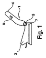
乗用車両用の車両シート1は、シート部品3及びバックレスト4を含む。バックレスト4は、シート部品3に対する傾斜が調整可能である。バックレスト4の傾斜を調整するべく、シート部品3及びバックレスト4間の遷移領域に水平方向に配列された駆動シャフト7が、例えばハンドホイール5のような手動で、又は例えば電動機のようなモータ駆動で回転される。駆動シャフト7は、車両シート1の2つの側部それぞれにおいて継手10に回転しないように係合する。駆動シャフト7は、以下で使用される円筒座標系の方向の詳細を画定する。
A vehicle seat 1 for a passenger vehicle includes a seat part 3 and a backrest 4. The inclination of the backrest 4 with respect to the seat component 3 can be adjusted. In order to adjust the inclination of the backrest 4, a drive shaft 7 arranged in the horizontal direction in the transition region between the seat part 3 and the backrest 4 can be manually operated, for example a handwheel 5 or a motor, for example an electric motor. It is rotated by driving. The drive shaft 7 is engaged with the
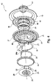
継手10は、互いに対して回転可能な第1継手部品11及び第2継手部品12を含む。2つの継手部品11及び12はそれぞれ、近似的に円板形状として記載することができる。以下で再び記載される個々の機能的幾何学形状が、第1継手部品11の円形の基本的幾何学形状から径方向に突出する。軸方向に作用する力の受容を目的として、すなわち継手部品11及び12の結束強度を目的として環状リング13が設けられる。環状リングを使用したかかる結束強度は、例えば米国特許第6,799,806号明細書に記載されている。好ましくは金属の環状リング13が、2つの継手部品11及び12の一方に固定接続される。本例では、第1継手部品11の外側エッジ部分に対して(少なくとも部分的に周方向が)、例えば溶接又はフランジ留めされる。環状リング13は、径方向内側を向いたエッジが、2つの継手部品11及び12の他方の径方向外側に対して可動に係合する。ここで、別個の滑りリングの介在も適用可能である。2つの継手部品11及び12の相対的な回転が妨げられることはない。すなわち、環状リング13と、これに固定接続された継手部品11又は12とが、それらに対して可動な2つの継手部品11及び12の他方を取り囲む。構造上、2つの継手部品11及び12はその結果、(環状リング13と)一緒になって円板状ユニットを形成する。
The joint 10 includes a first
継手10を車両シート1に締結した後、第1継手部品11は、以下に記載される自由枢動ロックがロック解除されない限り、バックレスト4に(ロック)接続される。第2継手部品12は、アダプタ112を介してシート部品3の構造物に固定接続、すなわち当該シート部品と一体化される。しかしながら、継手部品11及び12の割り当てを交換することも可能である。すなわち、この場合、第1継手部品11がシート部品と一体化され、かつ、第2継手部品12がバックレスト4に接続される。継手10は、バックレスト4及びシート部品3間の力の束の中にある。それゆえ、2つの継手部品11及び12は金属、好ましくは鋼からなる。
After fastening the joint 10 to the vehicle seat 1, the first
継手10は、調整及び固定を目的とする歯車ユニットによって、詳しくは、本例では、例えば独国特許出願公開第44 36 101(A1)号明細書に記載される自己ロック偏心経路歯車ユニットによって、第1継手部品11及び第2継手部品12が一緒に接続される歯車継手を含む。
The joint 10 is a gear unit for the purpose of adjustment and fixation, in particular in this example by a self-locking eccentric path gear unit as described, for example, in
歯車ユニットを形成するべく、第2継手部品12に外歯車ホイール16が形成され、かつ、第1継手部品11に内歯車リング17が形成される。これらは一緒に噛合する。歯車ホイール16の外歯車の歯先円の直径は、歯車リング17の内歯車の歯元円の直径よりも、少なくとも一つの歯高分小さい。これに対応する歯車ホイール16及び歯車リング17間の、少なくとも一歯という歯数の差異によって、歯車リング17は、歯車ホイール16上を転動することができる。その転動の結果、第1継手部品11及び第2継手部品12は互いに対して回転し、その結果、シート部品3に対するバックレスト4の傾斜が修正される。したがって、車両シート1の乗員はバックレストの傾斜を、自身の個人的な快適性要件に適応させることができる。
An
バックレストの快適性調整範囲は、ストッパ112aによって画定される。ストッパ112aは、シート部品と一体化されたアダプタ112に固定接続されて第1継手部品11の第1カム120及び第2カム130間に係合する。第1カム120及び第2カムは、機能的幾何学形状として、第1継手部品11の円形の基本的幾何学形状より上へ径方向に延びる。ストッパ112aに面する第1ストッパ面120aが第1カム120に形成され、かつ、ストッパ112aに面する第2ストッパ面130aが第2カム130に形成される。これらの一方がいずれの場合も、バックレストの快適性調整範囲の2つの端点の一方においてストッパ112aに当接することで、継手10のさらなる調整が防止される。第1ストッパ面120a及び第2ストッパ面130a間の間隔は、ストッパ面120a、130a間に存在するストッパ112aの寸法よりも大きい。その結果、バックレストの快適性調整範囲が画定される。
The comfort adjustment range of the backrest is defined by the stopper 112a. The stopper 112a is fixedly connected to the
歯車ホイール16及び歯車リング17の形成は、一回の打ち出し・スタンピング工程によって実行されるのが好ましい。これにより、継手部品11、12が、開始材料から同時にスタンピングされる。この代替として、同様の幾何学的形状及び同様の機能を備える継手部品11、12は、鍛造(例えば冷間押し出し又は熱間押し出し)によって製造することもできる。本例では、歯車ホイール16が、第2継手部品12の径方向外側エッジをなす。すなわち、第2継手部品12の外側が、歯車ホイール16によって径方向に終端する。
The
第2継手部品12は、歯車ホイール16と同心のカラー19を含む。カラー19は、カラー付き溝として当該継手部品に一体的に形成(すなわち一部品として形成)し又は別個のスリーブとして当該継手部品に締結することができる。カラー19には、駆動器21がハブ22によって回転可能に取り付けられる。駆動器21はプラスチック材料からなるのが好ましい。駆動器21のハブ22は、駆動シャフト7を受容するボア23と同心に設けられる。ボア23の輪郭は、本例ではスプラインである駆動シャフト7の輪郭に整合するように設けられる。駆動器21は、そのハブ22に接続されるカバーディスク25を含む。カバーディスク25は、ハブ22に一体的に形成され、かつ、ハブ22よりも直径が大きい。
The second
その外側曲面によって第1継手部品11を支承する2つのウェッジセグメント27が、その内側曲面によってカラー19上に支持される。これを目的として、最後に言及した継手部品の受容手段には、好ましくは回転しないように押し込められた滑り軸受ブッシング28が設けられる。滑り軸受ブッシング28には、ウェッジセグメント27の外側面が当接する。用語「支持」及び「支承」は、所定方向の力の束にある継手10に限られない。当該方向は継手10の組み付けに依存するからである。
Two
駆動器21は、ハブ22から径方向に離間したところに駆動器セグメント29を含む。駆動器セグメント29は、2つのウェッジセグメント27の狭い側部間と遊びを有して噛み合い、かつ、カバーディスク25及びハブ22と一体的に形成される。ウェッジセグメント27は、互いに向かい合う広い側部それぞれの、例えば突出した材料部品によって画定された開口又は凹みが、Ω字状のばね35の曲げられた端部フィンガ35aをいずれの場合も受容する。ばね35は、2つのウェッジセグメント27の周方向に作用し、特にそれらが分離するように押し広げる。2つのウェッジセグメント27の広い側部は動作中、互いに接触して作用し合うことができる。
The
駆動器21は、カラー19を含む継手部品の外側面において、クリップ留めされるのが好ましい保持リング43によって軸方向に固定される。保持リング43は、ハブ22の一部に沿って軸方向に延びる。ハブ22は、カラー19の内側面とは直接的に当接せずに、保持リング43が介在されてカラー19の中に取り付けられる(その結果、駆動器21は第2継手部品12に取り付けられる)。滑り軸受ブッシング28を含む継手部品(本例では第1継手部品11)の外側面には、径方向外側エッジ及びカバーディスク25間に、例えばゴム又は軟性プラスチック材料の封止リング44が存在する。封止リング44は、カバーディスク25に接続され、特にクリップ留めされる。
The
偏心方向へ延びることで歯車ホイール16を係合点において歯車リング17に押し付ける偏心器が、ウェッジセグメント27(及びばね35)によって画定される。(繰り返し)回転する駆動シャフト7による駆動の場合、トルクはまず駆動器21へ伝達され、その後、駆動器セグメント29によって偏心器へ伝達される。駆動器セグメント29は、滑り軸受ブッシング28に沿って摺動することにより偏心方向に変位させ、その結果、歯車リング17内の歯車ホイール16の係合点を変位させる。これは、揺らぎ転動、すなわち揺らぎが重畳された相対回転と表現される。その結果、バックレスト4の傾斜が、いくつかの使用位置間で無段階的に調整可能となる。
An eccentric that extends in the eccentric direction and presses the
動的な動作性能を改善するべく、他の阻止要素として保持ばね51が設けられるのが好ましい。これは、例えば独国特許第195 48 809(C1)号明細書に記載されている。保持ばね51は、本例では歯55と相互作用をする。歯55は、さらなる歯車リングとして第1継手部品11に形成される。保持ばね51は、(保持ばね51が端部フィンガ35aに当接してばね35を阻止することにより)各ウェッジセグメント27を阻止して非駆動状態にし、かつ、駆動された駆動器21によって解放される。
In order to improve the dynamic operating performance, a holding
複数のコンポーネントを包含する歯車継手として形成される当該円板状ユニットとは別に、各継手10は自由枢動装置も含む。第3継手部品74が、第1継手部品11に締結された支承リング71によって、第1継手部品11の、第2継手部品12から離れた側部に取り付けられる。実質的に平板状の第3継手部品74は、バックレスト4のバックレスト構造物に接続され、第1継手部品11に対して中心が有効な自由枢動を目的として、(支承リング71によって画定される)中心軸Aまわりに枢動可能となる。中心軸Aは、伝動ロッド7に対して平行に存在する。反対のことが述べられない限り、以下に記載の回転はすべて、軸Aに対して平行に整合された回転軸まわりで行われる。
Apart from the disk-like unit formed as a gear joint containing a plurality of components, each joint 10 also includes a free pivot device. The third
車両シート1が使用されている場合、第3継手部品74は第1継手部品11にロックされている。これを目的として継手部品11は、第1継手部品11の円形の基本的幾何学形状を超えて径方向に突出する突起140をさらなる動作的幾何学形状として備える。突起140は、支承ボルト82によって、第1継手部品11に面する第3継手部品74の側部に回転可能に取り付けられた爪80と相互作用をする。
When the vehicle seat 1 is used, the third
爪80は、長脚部及び短脚部を備えるL字状に類似した基本的幾何学形状を有する。短脚部から離れた長脚部の端領域にある円形孔が、支承ボルト82を受容するべく機能し、かつ、当該支承ボルトと一緒になって第3継手部品74の第1枢動点D1に爪80の支承点を形成する。爪80の長脚部及び短脚部間の接続領域には、突起140のロック面140bとの相互作用を目的としてロックカム80aが形成される。第3継手部品74を第1継手部品11にロックするべく、ロックカム80aは、突起140のロック面140bにおいて自由枢動方向に支持される。
The
第3継手部品74においてストッパとして機能する偏心ボルト84が、バックレスト2の後ろ枢動方向(図5、9、10、11及び12では反時計回り方向)の、第3継手部品74の枢動を画定するべく機能する。偏心ボルト84は、ひとたび自由枢動が完了してバックレスト4の使用位置に再び到達すると、突起140の支持面140aに当接するようになる。製造公差を補償するべく、偏心ボルト84には軸方向に、互いに偏心の実質的に円筒状の段による段差が付けられる。第3継手部品74の円形孔に挿入された偏心ボルト84の円筒部分は、径方向の偏心度だけ、偏心ボルト84のさらなる円筒部分へと径方向にずらされる。当該さらなる円筒部分は、使用位置に再び到達すると、支持面140aに当接するようになる。偏心ボルト84が、第3継手部品74に挿入された円筒部分まわりに回転すると、その結果、支持面140aに当接するように動くことができる円筒部分が、半径が当該偏心度に対応する円経路に沿って動かされる。継手の組み付け中、偏心ボルト84は、第1継手部品11に対する第3継手部品74の公称位置が設定されるまで、第3継手部品74に対して一定量だけ回転する。偏心ボルト84はその後、第3継手部品74に固定され、特に、当該第3継手部品に溶接される。
The
製造公差を補償するべく、支承ボルト82もまた、対応する偏心段付き態様で構成することができる。この場合、第3継手部品74の円形孔に挿入された支承ボルト82の円筒部分は、平行中心軸から径方向にずれた中心軸を有する。この中心軸は、爪80の支承配列を目的として機能する円筒部分82の第1枢動点D1を画定する。その結果、支承ボルト82の偏心度が画定される。支承ボルト82が、第3継手部品74に挿入された円筒部分まわりに回転すると、第1枢動点D1は、半径が当該偏心度に対応する円経路に沿って動かされる。継手の組み付け中、支承ボルト82は、第1枢動点D1が最適位置に到達するまで第3継手部品74に対して一定量だけ回転されるので、爪80は、ロックカム80aの最大の係合によって突起140のロック面140bと、遊びなしで係合するが、自己ロックの角度範囲外にある。当該支承ボルトはその後、第3継手部品74に固定され、特に、当該第3継手部品に溶接される。
To compensate for manufacturing tolerances, the bearing
ロックカム90は、第1継手部品11に面する側にあって第1枢動点D1から離間した第2枢動点D2において、第3継手部品74上で回転可能に取り付けられる。これを目的として、ロックカム90は、一端に軸受シャフト90aを含む。軸受シャフト90aは、ロックカム90から垂直に突出し、軸Aに対して平行に延び、かつ、ブッシング94によって第3継手部品74の開口に挿入される。軸受シャフト90aの自由端は、第3継手部品74を貫通して延び、かつ、爪80から離れた側において、第3継手部品74の実質的に平板状の基本的幾何学形状を超えて突出する。軸受シャフト90aの自由端は、一定の輪郭が形成され、特に、多角形の形状とされる。対応する相補輪郭が形成されたコンポーネントを、軸方向に介在させることができる。その結果、軸受シャフト90a及び介在されたコンポーネント間に位置固定接続が得られる。介在されたコンポーネントとは、本例では、図示しないレバーである。これは、バックレスト4の上領域に締結されたハンドレバー8によって引っ張られるケーブルと動作可能に接続される。ハンドレバー8の作動によって軸受シャフト90aが回転し、それに引き続いてロックカムが第2枢動点D2まわりに回転する。
The
均等に細長い基本形状を備える結合器98の、第3枢動点D3にある第1端が、軸受シャフト90aから離れたロックカム90の端に接続される。結合器98の第2端は、第4枢動点D4にある爪80の短脚部に接続される。
A first end at a third pivot point D3 of a
第3枢動点D3が、軸受シャフト90aから離れたロックカム90の端において軸Aに対して平行に延びた円筒シャフト90bによって形成される。円筒シャフト90bは、結合器98の第1端の長孔に係合する。円筒シャフト90bと結合器98の長孔とが対となる結果、第3枢動点D3が、回転及び摺動関節として形成される。これにより、純粋な回転動のほか、結合器98及びロックカム90間の長孔状幾何学形状によって画定される並進動も可能となる。
A third pivot point D3 is formed by a
第4枢動点D4は、爪80の短脚部の端領域にある結合器98の第2端の円形孔に挿入されたリベット96によって形成される。リベット96は、純粋な回転関節がもたらされるようにリベット留めされる。
The fourth pivot point D4 is formed by a
第3継手部品74の第1枢動点D1に取り付けられた爪80、第3継手部品74の第2枢動点D2に取り付けられたロックカム90、並びに第3枢動点D3のロックカム90に及び第4枢動点D4の爪80に枢動可能に接続された結合器98が、(第3継手部品74に枢動可能に取り付けられた)実質的に平坦な四棒チェーンを画定する。これは、自由枢動機能のロック及びロック解除を目的として機能する。
The
第3継手部品74に締結されたカバー78が、自由枢動装置の上記個々の部品を少なくとも部分的に被覆してこれらを汚染から保護する。支承ボルト82、ロックカム90及び偏心ボルト84は、第3継手部品74の各孔に支承配列されるとともに、カバー78において対向孔パターンで支持され又は取り付けられる。
A
図9〜12は、自由枢動機能のロック解除及びロックを示す。図9は、使用位置のロック状態を示す。爪80がロックされる。すなわち、ロックカム80aが、ロック面140bに支持される。ロックカム90及び第3継手部品74間で有効なばね92によって、ロックカム90には、爪80に当接する方向への(図9における反時計回り方向の)トルクが作用する。爪80は、その結果、通常の動作負荷を受けてロック位置に保持される。第3枢動点D3は、第2枢動点D2及び第4枢動点D4間の仮想接続線L上に存在し、又は(公差位置に応じて)わずかに接続線L及び爪80間に存在する。その結果、ロックカム90及び結合器98は、ほぼ一直線に整合される。カム90は、第3枢動点D3がさらに爪80の方向に動くことができないように、側方が爪80に支持される。その結果、四棒チェーンは、阻止(死点)位置に位置決めされる。高い衝突力が爪80に作用しても、ロックカム90及び結合器98の伸長した位置並びにカム90の爪80による支持に起因して、爪80を開くことはできない。第3枢動点D3が回転及び摺動関節として設計される場合、衝突事象があると、画定された小さな並進動経路は、その関節を介して軸受シャフト90aが結合器98の長孔のエッジに当接するまで動かされる。
9-12 show unlocking and locking of the free pivot function. FIG. 9 shows a locked state of the use position. The
図10は、自由枢動機能のロック解除中の継手10を示す。ハンドレバー8の作動により、ロックカム90は、ばね92の力に対抗して爪80から離れるように(図10における時計回り方向に)枢動される。第3枢動点D3が、爪80から離れた接続線Lの側部上へ動かされる。結合器98により、ロックカム90は、爪80をロック位置から外れるように引っ張る。その結果、爪80のロックカム80aはもはや、ロック面140bと当接することがなくなるので、バックレスト4を含む第3継手部品74が自由枢動方向へ可動となる。バックレスト4は自由に枢動することができる。上述したように、第3枢動点D3が、自由枢動装置のロック状態において接続線L及び爪80間に存在する場合、第3枢動点D3が回転及び摺動関節として設計されることにより、ロック解除動作中において、第3枢動点D3が、当該伸長した位置を、すなわち接続線Lを超えることが可能となる。修正設計では、第3枢動点D3の代わりに、他の枢動点D1、D2、D4が回転及び摺動関節として形成される。残りの枢動点D1、D2、D3、D4が純粋な回転関節として形成される。
FIG. 10 shows the joint 10 during unlocking of the free pivot function. By the operation of the hand lever 8, the
すべての公差条件下で自由枢動機能の確実なロック解除を可能とするべく、爪80は、図11に見えるように、開方向へさらにわずかに枢動することができる。
To allow for reliable unlocking of the free pivot function under all tolerance conditions, the
図12に示される自由枢動動作中、爪80のロックカム80aは、突起140の径方向外側境界上に載置されて当該境界に沿って摺動する。その結果、ハンドレバー8は、小さな自由枢動角度の後であっても、爪80が再びロックされることなく非作動のままとすることができる。
During the free pivoting operation shown in FIG. 12, the
第3継手部品74の、ひいてはバックレスト4の枢動戻り及びロックが逆の順序で有効とされる。
The pivotal return and locking of the third
図5に示されかつ支承ボルト82に締結された保持ばね86の、軸方向に付勢されるばねアーム86aが、突起140に当接する。第3継手部品74が明らかに前方に枢動されると、ばねアーム86aは突起140から離れて爪80に向かって弾性力を及ぼす。その結果、爪80が、支持面140aの後ろをロックすることが防止される。
An axially biased
本発明によれば、突起140は、第1継手部品11に一体的に形成される。すなわち、突起140は、第1継手部品11の一体コンポーネントを材料ユニットとして形成し、かつ、別個に製造されて引き続き締結されるコンポーネントではない。第1カム120及び第2カム130も、第1継手部品11に(又は環状リング13に若しくは支承リング71に)一体的に形成されるのが好ましい。本発明に係るソリューションは、図4及び6に示される実質的に平坦は形態を有する環状リング13による恩恵を受ける。環状リング13は、いずれの場合も、第1継手部品11に複数箇所において重なるように係合し、ひいては第1継手部品11のエッジ上の径方向に延びる材料部品となり得る。
According to the present invention, the
突起140及び爪80に対しては異なる設計も可能である。修正された設計では、爪80は、突起140におけるいくつかの歯空間と相互作用するいくつかの歯を含み得る。
Different designs for the
上述の記載、特許請求の範囲及び図面に開示された特徴は、本発明の異なる開発での実現にとって、個別又は組み合わせの双方において重要となり得る。 The features disclosed in the above description, the claims and the drawings can be important both individually or in combination for the realization of different developments of the invention.
1 車両シート
3 シート部品
4 バックレスト
5 ハンドホイール
7 駆動シャフト
8 ハンドレバー
10 継手
11 第1継手部品
12 第2継手部品
13 環状リング
16 歯車ホイール
17 歯車リング
19 カラー
21 駆動器
22 ハブ
23 ボア
25 カバーディスク
27 ウェッジセグメント
28 滑り軸受ブッシング
29 駆動器セグメント
35 ばね
35a 端部フィンガ
43 保持リング
44 封止リング
51 保持ばね
55 歯
71 支承リング
74 第3継手部品
78 カバー
80 爪
80a ロックカム
82 支承ボルト
84 偏心ボルト
86 保持ばね
86a ばねアーム
90 ロックカム
90a 軸受シャフト
90b シャフト
92 ばね
94 ブッシング
96 リベット
98 結合器
112 アダプタ
112a ストッパ
120 第1カム
120a 第1ストッパ面
130 第2カム
130a 第2ストッパ面
140 突起
140a 支持面
140b ロック面
A 軸
D1 第1枢動点
D2 第2枢動点
D3 第3枢動点
D4 第4枢動点
L 接続線(D2〜D4)
DESCRIPTION OF SYMBOLS 1 Vehicle seat 3 Seat components 4 Backrest 5 Hand wheel 7 Drive shaft 8
Claims (14)
b)前記第1継手部品(11)に対して枢動可能に前記第1継手部品(11)に取り付けられた第3継手部品(74)であって、前記第3継手部品(74)の第1枢動点(D1)に取り付けられた爪(80)によって前記第1継手部品(11)に対してロック可能な第3継手部品(74)と
を有する車両シート用の継手(10)であって、
c)前記第3継手部品(74)と、
前記第3継手部品(74)の第2枢動点(D2)に取り付けられたロックカム(90)と、
第3枢動点(D3)が前記ロックカム(90)に及び第4枢動点(D4)が前記爪(80)に枢動可能に接続された結合器(98)と、
前記爪(80)と
が四棒連動部材(74、80、98、90)を画定し、
前記四棒連動部材(74、80、98、90)の枢動点(D1、D2、D3、D4)の一つは回転及び摺動関節として形成され、
前記四棒連動部材(74、80、98、90)は、ばね(92)によって前記爪(80)のロック位置の方向に付勢される継手(10)。 a) a first joint part (11) and a second joint part (12) that are rotatable relative to each other and geared together;
b) a third joint part (74) attached to the first joint part (11) so as to be pivotable relative to the first joint part (11), wherein the third joint part (74) A joint (10) for a vehicle seat having a third joint part (74) that can be locked to the first joint part (11) by a claw (80) attached to one pivot point (D1). And
and c) the third coupling part (74),
A locking cam (90) attached to a second pivot point (D2) of the third joint component (74);
A coupler (98) having a third pivot point (D3) pivotally connected to the locking cam (90) and a fourth pivot point (D4) pivotally connected to the pawl (80);
Said pawl (80) and four bar interlocking member (74, 80, 98, 90) ,
One of the pivot points (D1, D2, D3, D4) of the four-bar interlocking member (74, 80, 98, 90) is formed as a rotating and sliding joint,
The four-bar linkage member (74,80,98,90) is a spring (92) by said claws (80) fitting that will be biased toward the locked position (10).
前記軸受シャフト(90a)は、前記第3継手部品(74)の開口に回転可能に取り付けられることによって前記第2枢動点(D2)を形成する、請求項1から9のいずれか一項に記載の継手(10)。 The lock cam (90) includes a bearing shaft (90a),
10. The bearing shaft (90a) according to any one of claims 1 to 9 , wherein the bearing shaft (90a) is rotatably mounted in an opening of the third joint part (74) to form the second pivot point (D2). The coupling (10) described.
前記第2継手部品(12)に接続されたシート部品(3)と、
前記第3継手部品(74)に接続されたバックレスト(4)と
を有する車両シート。 A vehicle sheet having at least one joint (10) according to any one of claims 1 1 3,
A seat part (3) connected to the second joint part (12);
A vehicle seat having a backrest (4) connected to the third joint component (74).
Applications Claiming Priority (5)
| Application Number | Priority Date | Filing Date | Title |
|---|---|---|---|
| DE102012012852.5 | 2012-06-26 | ||
| DE102012012852.5A DE102012012852B4 (en) | 2012-06-26 | 2012-06-26 | Fitting for a vehicle seat and vehicle seat |
| DE102013002819 | 2013-02-14 | ||
| DE102013002819.1 | 2013-02-14 | ||
| PCT/EP2013/062958 WO2014001207A1 (en) | 2012-06-26 | 2013-06-21 | Fitting for a vehicle seat, and vehicle seat |
Publications (2)
| Publication Number | Publication Date |
|---|---|
| JP2015504818A JP2015504818A (en) | 2015-02-16 |
| JP5865518B2 true JP5865518B2 (en) | 2016-02-17 |
Family
ID=48790349
Family Applications (1)
| Application Number | Title | Priority Date | Filing Date |
|---|---|---|---|
| JP2014553766A Active JP5865518B2 (en) | 2012-06-26 | 2013-06-21 | Fitting for vehicle seat and vehicle seat |
Country Status (7)
| Country | Link |
|---|---|
| US (1) | US9371016B2 (en) |
| EP (1) | EP2864154B1 (en) |
| JP (1) | JP5865518B2 (en) |
| KR (1) | KR101605102B1 (en) |
| CN (1) | CN104114407B (en) |
| PL (1) | PL2864154T3 (en) |
| WO (1) | WO2014001207A1 (en) |
Families Citing this family (7)
| Publication number | Priority date | Publication date | Assignee | Title |
|---|---|---|---|---|
| EP2956333B1 (en) * | 2013-02-14 | 2016-06-15 | Johnson Controls Components GmbH & Co. KG | Detent fitting for a vehicle seat, and vehicle seat |
| DE112014000432B4 (en) * | 2013-06-27 | 2022-08-25 | Das Co., Ltd | Reclining device for a vehicle seat |
| US10150388B2 (en) * | 2014-10-15 | 2018-12-11 | Adient Luxembourg Holding S.à.r.l. | Actuating device, in particular for a vehicle seat, and vehicle seat |
| JP6780454B2 (en) * | 2016-11-09 | 2020-11-04 | トヨタ紡織株式会社 | Back frame for vehicle seat |
| KR102532358B1 (en) | 2018-07-10 | 2023-05-16 | 생-고뱅 퍼포먼스 플라스틱스 렌콜 리미티드 | Torque assemblies and methods of making and using them |
| US11535134B2 (en) * | 2021-01-19 | 2022-12-27 | Ford Global Technologies, Llc | Vehicle seating assembly |
| CN113401016B (en) * | 2021-07-27 | 2022-07-12 | 恺博(常熟)座椅机械部件有限公司 | Manual turnover device for automobile seat backrest and automobile seat |
Family Cites Families (29)
| Publication number | Priority date | Publication date | Assignee | Title |
|---|---|---|---|---|
| JPS63183013A (en) * | 1987-01-26 | 1988-07-28 | 池田物産株式会社 | Reclining apparatus |
| US5224759A (en) * | 1989-08-31 | 1993-07-06 | Fuji Kiko Co., Ltd. | Double lock recliner for automotive seat |
| DE4436101C5 (en) | 1993-11-30 | 2008-12-11 | Keiper Gmbh & Co.Kg | Lehneneinstellbeschlag for seats with adjustable backrest, in particular motor vehicle seats |
| DE19548809C1 (en) | 1995-12-27 | 1997-05-22 | Keiper Recaro Gmbh Co | Adjustment and fixture device for road vehicle seat |
| US5733008A (en) * | 1996-12-09 | 1998-03-31 | Atoma International, Inc. | Safety lock for non-linear recliner mechanism |
| DE10105282B4 (en) | 2001-02-06 | 2005-03-24 | Keiper Gmbh & Co. Kg | Fitting for a vehicle seat |
| DE10107237C5 (en) * | 2001-02-16 | 2011-05-05 | Faurecia Autositze Gmbh | Adjustment device for motor vehicle seats |
| DE10109397C1 (en) * | 2001-02-27 | 2002-10-24 | Faurecia Autositze Gmbh & Co | Adjustment and folding linkage for vehicle seat has hinge joining rear end of seat to lower end of backrest and includes lever arms and ratchet discs |
| JP3833936B2 (en) * | 2001-12-25 | 2006-10-18 | アイシン精機株式会社 | Sheet device |
| CN100488802C (en) * | 2002-09-27 | 2009-05-20 | 布罗泽汽车部件制造科堡两合公司 | Seat arrangement for a motor vehicle seat |
| DE10246473A1 (en) | 2002-09-27 | 2004-04-08 | Brose Fahrzeugteile Gmbh & Co. Kommanditgesellschaft, Coburg | Seat arrangement for motor vehicle seat has backrest adjustable by means of lever device relative to seat mounting frame |
| DE10337682A1 (en) * | 2003-08-11 | 2005-03-24 | Brose Fahrzeugteile Gmbh & Co | Automotive seat |
| DE102005003818B4 (en) * | 2005-01-27 | 2008-06-19 | Faurecia Autositze Gmbh | Vehicle seat with folding backrest |
| WO2007000307A2 (en) * | 2005-06-27 | 2007-01-04 | Johnson Controls Gmbh | Locking and releasing mechanism comprising a safety catch to prevent self-opening |
| JP4770389B2 (en) * | 2005-10-21 | 2011-09-14 | アイシン精機株式会社 | Vehicle seat device |
| US7503099B2 (en) * | 2005-10-25 | 2009-03-17 | Fisher Dynamics Corporation | Memory mechanism for an adjustment mechanism |
| DE102006003243B4 (en) * | 2006-01-24 | 2011-04-14 | Keiper Gmbh & Co. Kg | Fitting for a vehicle seat |
| DE102006044490B4 (en) * | 2006-01-24 | 2008-08-28 | Keiper Gmbh & Co.Kg | Fitting for a vehicle seat |
| DE502006007456D1 (en) * | 2006-01-24 | 2010-08-26 | Keiper Gmbh & Co Kg | FITTING FOR A VEHICLE SEAT |
| JP4968776B2 (en) * | 2006-08-18 | 2012-07-04 | テイ・エス テック株式会社 | Vehicle seat |
| DE102008017019A1 (en) | 2007-06-20 | 2008-12-24 | C. Rob. Hammerstein Gmbh & Co. Kg | Articulated fitting for motor vehicle seats and with a round plate |
| DE102008008935B3 (en) * | 2008-02-08 | 2009-09-03 | Keiper Gmbh & Co. Kg | Fitting for a vehicle seat |
| DE102008029438B4 (en) * | 2008-06-16 | 2014-05-22 | Keiper Gmbh & Co. Kg | Fitting for a vehicle seat |
| US7871127B2 (en) * | 2008-08-01 | 2011-01-18 | Bae Industries, Inc. | Seat recliner/dump mechanism such as incorporated into a seatback slaved to a floor latch release |
| WO2011019922A1 (en) * | 2009-08-12 | 2011-02-17 | Johnson Controls Technology Company | Modular recline mechanism and sidemember for rotary recliner |
| CA2782904C (en) * | 2009-12-04 | 2017-08-15 | Fisher & Company, Incorporated | Seat mechanism with easy-entry feature |
| US8313145B2 (en) * | 2010-03-11 | 2012-11-20 | Keiper Gmbh Co. Kg | Fitting for a vehicle seat |
| EP2571719A1 (en) * | 2010-05-17 | 2013-03-27 | Magna Seating Inc. | Vehicle seat assembly with easy-entry mechanism |
| DE102011106284B4 (en) * | 2011-07-01 | 2022-10-20 | Keiper Seating Mechanisms Co., Ltd. | Fitting system for a vehicle seat and vehicle seat |
-
2013
- 2013-06-21 US US14/375,628 patent/US9371016B2/en active Active
- 2013-06-21 EP EP13736789.2A patent/EP2864154B1/en active Active
- 2013-06-21 WO PCT/EP2013/062958 patent/WO2014001207A1/en active Application Filing
- 2013-06-21 PL PL13736789.2T patent/PL2864154T3/en unknown
- 2013-06-21 JP JP2014553766A patent/JP5865518B2/en active Active
- 2013-06-21 CN CN201380008157.2A patent/CN104114407B/en active Active
- 2013-06-21 KR KR1020147027441A patent/KR101605102B1/en active IP Right Grant
Also Published As
| Publication number | Publication date |
|---|---|
| KR20140131563A (en) | 2014-11-13 |
| US20140361594A1 (en) | 2014-12-11 |
| CN104114407B (en) | 2016-08-31 |
| JP2015504818A (en) | 2015-02-16 |
| PL2864154T3 (en) | 2016-10-31 |
| US9371016B2 (en) | 2016-06-21 |
| WO2014001207A1 (en) | 2014-01-03 |
| EP2864154A1 (en) | 2015-04-29 |
| CN104114407A (en) | 2014-10-22 |
| EP2864154B1 (en) | 2016-04-20 |
| KR101605102B1 (en) | 2016-03-21 |
Similar Documents
| Publication | Publication Date | Title |
|---|---|---|
| JP5865518B2 (en) | Fitting for vehicle seat and vehicle seat | |
| US9033418B2 (en) | Fitting for a vehicle seat | |
| US9039088B2 (en) | Fitting for a vehicle seat | |
| CA2832350C (en) | Disc recliner with internal leaf springs | |
| US7390061B2 (en) | Device for adjustment of level of inclination of back part of motor vehicle seat | |
| US9108541B2 (en) | Recliner system for a vehicle seat | |
| US7571962B2 (en) | Fitting for a vehicle seat | |
| US9272649B2 (en) | Angle adjustment device for vehicle seat | |
| JP5674998B2 (en) | Joint system for vehicle seat | |
| JP5736523B2 (en) | Fitting for vehicle seat and vehicle seat | |
| JP5609889B2 (en) | Locking device | |
| JP2005502438A (en) | Vehicle seat fittings | |
| KR101155672B1 (en) | Fitting for the seat of a vehicle | |
| US9227542B2 (en) | Fitting system for a vehicle seat | |
| JP5905609B2 (en) | Fitting for vehicle seat and vehicle seat | |
| JP2008506481A (en) | Vehicle seat fittings | |
| CN102481870A (en) | Fitting for a vehicle seat | |
| US9919628B2 (en) | Fitting for a vehicle seat, method for assembling a fitting for a vehicle seat, and vehicle seat | |
| JP2008534182A (en) | Vehicle seat and its disc recliner | |
| CN105189195B (en) | Detent fitting for a vehicle seat, and vehicle seat | |
| US8313145B2 (en) | Fitting for a vehicle seat | |
| WO2015027309A1 (en) | Disc recliner with two stage internal leaf springs |
Legal Events
| Date | Code | Title | Description |
|---|---|---|---|
| A977 | Report on retrieval |
Free format text: JAPANESE INTERMEDIATE CODE: A971007 Effective date: 20150813 |
|
| A131 | Notification of reasons for refusal |
Free format text: JAPANESE INTERMEDIATE CODE: A131 Effective date: 20150818 |
|
| A521 | Request for written amendment filed |
Free format text: JAPANESE INTERMEDIATE CODE: A523 Effective date: 20151019 |
|
| TRDD | Decision of grant or rejection written | ||
| A01 | Written decision to grant a patent or to grant a registration (utility model) |
Free format text: JAPANESE INTERMEDIATE CODE: A01 Effective date: 20151208 |
|
| A61 | First payment of annual fees (during grant procedure) |
Free format text: JAPANESE INTERMEDIATE CODE: A61 Effective date: 20151225 |
|
| R150 | Certificate of patent or registration of utility model |
Ref document number: 5865518 Country of ref document: JP Free format text: JAPANESE INTERMEDIATE CODE: R150 |
|
| R250 | Receipt of annual fees |
Free format text: JAPANESE INTERMEDIATE CODE: R250 |
|
| R250 | Receipt of annual fees |
Free format text: JAPANESE INTERMEDIATE CODE: R250 |
|
| R250 | Receipt of annual fees |
Free format text: JAPANESE INTERMEDIATE CODE: R250 |
|
| S111 | Request for change of ownership or part of ownership |
Free format text: JAPANESE INTERMEDIATE CODE: R313111 Free format text: JAPANESE INTERMEDIATE CODE: R313113 |
|
| R350 | Written notification of registration of transfer |
Free format text: JAPANESE INTERMEDIATE CODE: R350 |
|
| R360 | Written notification for declining of transfer of rights |
Free format text: JAPANESE INTERMEDIATE CODE: R360 |
|
| R360 | Written notification for declining of transfer of rights |
Free format text: JAPANESE INTERMEDIATE CODE: R360 |
|
| R371 | Transfer withdrawn |
Free format text: JAPANESE INTERMEDIATE CODE: R371 |
|
| S111 | Request for change of ownership or part of ownership |
Free format text: JAPANESE INTERMEDIATE CODE: R313113 |
|
| R360 | Written notification for declining of transfer of rights |
Free format text: JAPANESE INTERMEDIATE CODE: R360 |
|
| S111 | Request for change of ownership or part of ownership |
Free format text: JAPANESE INTERMEDIATE CODE: R313113 |
|
| R250 | Receipt of annual fees |
Free format text: JAPANESE INTERMEDIATE CODE: R250 |
|
| R370 | Written measure of declining of transfer procedure |
Free format text: JAPANESE INTERMEDIATE CODE: R370 |
|
| R350 | Written notification of registration of transfer |
Free format text: JAPANESE INTERMEDIATE CODE: R350 |
|
| R250 | Receipt of annual fees |
Free format text: JAPANESE INTERMEDIATE CODE: R250 |
|
| S111 | Request for change of ownership or part of ownership |
Free format text: JAPANESE INTERMEDIATE CODE: R313113 |
|
| R360 | Written notification for declining of transfer of rights |
Free format text: JAPANESE INTERMEDIATE CODE: R360 |
|
| R360 | Written notification for declining of transfer of rights |
Free format text: JAPANESE INTERMEDIATE CODE: R360 |
|
| R371 | Transfer withdrawn |
Free format text: JAPANESE INTERMEDIATE CODE: R371 |
|
| S111 | Request for change of ownership or part of ownership |
Free format text: JAPANESE INTERMEDIATE CODE: R313113 |
|
| R350 | Written notification of registration of transfer |
Free format text: JAPANESE INTERMEDIATE CODE: R350 |