EP2350533B1 - Gargerät mit einer strömungsleitvorrichtung - Google Patents
Gargerät mit einer strömungsleitvorrichtung Download PDFInfo
- Publication number
- EP2350533B1 EP2350533B1 EP09748082.6A EP09748082A EP2350533B1 EP 2350533 B1 EP2350533 B1 EP 2350533B1 EP 09748082 A EP09748082 A EP 09748082A EP 2350533 B1 EP2350533 B1 EP 2350533B1
- Authority
- EP
- European Patent Office
- Prior art keywords
- flow guide
- guide member
- fan
- cooking
- flow
- Prior art date
- Legal status (The legal status is an assumption and is not a legal conclusion. Google has not performed a legal analysis and makes no representation as to the accuracy of the status listed.)
- Active
Links
Images


Classifications
-
- F—MECHANICAL ENGINEERING; LIGHTING; HEATING; WEAPONS; BLASTING
- F24—HEATING; RANGES; VENTILATING
- F24C—DOMESTIC STOVES OR RANGES ; DETAILS OF DOMESTIC STOVES OR RANGES, OF GENERAL APPLICATION
- F24C15/00—Details
- F24C15/32—Arrangements of ducts for hot gases, e.g. in or around baking ovens
- F24C15/322—Arrangements of ducts for hot gases, e.g. in or around baking ovens with forced circulation
-
- F—MECHANICAL ENGINEERING; LIGHTING; HEATING; WEAPONS; BLASTING
- F24—HEATING; RANGES; VENTILATING
- F24C—DOMESTIC STOVES OR RANGES ; DETAILS OF DOMESTIC STOVES OR RANGES, OF GENERAL APPLICATION
- F24C15/00—Details
- F24C15/32—Arrangements of ducts for hot gases, e.g. in or around baking ovens
Definitions
- the present invention relates to a cooking appliance having an interior space, a blower device and a flow guiding device, which has at least one fan wheel in an interior of the cooking device for circulating atmosphere, comprising at least a first flow guide for subdividing the interior space into a pressure space with the fan wheel and a cooking chamber.
- each second flow guide fulfills a nozzle function, hineinerstreckt from the fan means into the cooking chamber and projects beyond the edge of the suction opening of the first Strömungsleitglieds or overlaps.
- a first flow-guiding element in the form of a baffle plate is used between a cooking chamber and a fan chamber or pressure chamber, which has a central suction opening and expels blowing openings to the wall of the interior, so that a fan arranged in the pressure chamber atmosphere from the cooking chamber suck in through the intake and can blow out through the exhaust ports.
- the DE 203 14 818 UI deals with a targeted blowing of atmosphere from the pressure chamber into the cooking chamber via specially arranged blow-out in the first flow control.
- exhaust openings of a first Strömungsleitgliedes deals with the not pre-published DE 10 2007 023 767 , where there movable elements are to be arranged in exhaust openings, which move in dependence on the pressure curve in the cooking chamber.
- Another approach can be found for example in the DE 203 09 268 UI by using second Strömungsleitglieder in the fan room, to be forced through the tearing of vertebrae when passing through a blowout between the pressure chamber and the cooking chamber, so that propagate vortex in the oven.
- Second Strömungsleitglieder for enforcing a homogeneous flow in the oven are also in the DE 203 12 031 UI disclosed.
- Another flow guide is, for example, the DE 10 2004 004 393 B4 can be seen in which a first flow control in a running with a second flow control in the region of its intake. More specifically, the edge of the first flow guide in the form of a baffle is bent in the region of its suction opening to form a flow-guiding nozzle.
- This nozzle represents a suction nozzle and is intended to improve the suction of atmosphere from a cooking chamber in a fan room of a cooking appliance.
- the disadvantage is that there must always be a gap between a rotating fan in the pressure chamber on the one hand and the suction on the air baffle on the other hand to avoid damage.
- This gap is due to tolerances, especially in cooking appliances of the large kitchen large enough to allow atmosphere from the pressure chamber to flow directly into the intake of the fan wheel, so not passed through a blowout in the oven and via the intake of the baffle in the intake of the fan To be, so that it comes to a short circuit with the flowing from the oven through the intake opening of the baffle atmosphere. For this reason, this is passing through the gap Flow also called short-circuit flow and occurs in a very sensitive place in the intake of the fan wheel, namely in the deflection of a main flow from the cooking chamber into the pressure chamber, more precisely where a deflection takes place from a radial direction in an axial direction of the main flow.
- the short-circuit flow is transverse to the main flow in the intake of the fan, so that it narrows the main flow and even a detachment and turbulence of the main flow can result, resulting in an overall reduction in the efficiency of the circulation of Garraumatmospreheat by the fan.
- Flow guides for cooking appliances are also both in the EP 1 767 869 A2 as well as the DT 25 19 604 described, wherein in both cases, a first flow control propagates at least to the suction of a fan wheel, in the case of DT 25 19 604 hineinerstreckt even in the suction, while the second flow guide is provided in the form of an outer contour of the fan ,
- the GB 1414546 discloses another cooking appliance having a flow guide device comprising two flow directing members.
- a generic cooking appliance In a generic cooking appliance according to the DE 34 28 330 A1 causes a fan to flow through a cooking chamber with hot air, wherein a portion of the sucked air from the fan to a heater and from there through a return duct is returned to the fan again.
- blades of the blower In the area of the mouth of this return channel, blades of the blower pass by, which eject the air supplied through the return duct and possibly also part of the air taken in by the blades from the cooking chamber in the radial direction.
- Object of the present invention is to develop the generic cooking appliance with flow guide such that the efficiency of circulation within the interior of the cooking appliance is improved.
- This object is achieved in that the first flow guide spreads to every second flow.
- the blower device comprises at least one radial fan, which has a plurality of blades attached to a holding device, in particular in the form of a support ring, and arranged concentrically with a drivable shaft, the second flow guide element on the shaft, the holding device, in particular the support ring, and / or at least one blade, attached or formed therewith.
- the second flow-guiding element comprises a ring shape, in particular when attached to the holding device or formed on the holding device.
- the invention also proposes that every second flow-guiding element extends in the pressure chamber into the pressure region of the fan wheel.
- each second flow-guiding element has a cross-sectional shape such that a flow from the cooking chamber into the pressure chamber as far as possible in the pressure space is detached from the axial main flow, preferably a substantially hook-shaped cross-section or, in particular asymmetrically, U-shaped Cross-section is formed with an extended free end of the second flow control in the pressure chamber.
- the invention proposes that the first flow guide is attached or attachable to a wall of the interior.
- a third flow-guiding element in the pressure chamber which delimits in particular a blow-out region of the radial fan which widens conically radially outward from the fan wheel of the radial fan.
- the third Strömungsleitglied is attached to the first flow guide or formed together with the same.
- the third flow-guiding element is an extension of the second flow-guiding element, in particular at the free end of the second flow-guiding element in the pressure chamber.
- the first flow-guiding member, the second flow-guiding member and / or the third flow-guiding member are each formed from at least one stamped and bent part and / or sheet and / or detachably fastened and / or at least partially or in sections movable.
- the end of the second flow-guiding element in the pressure chamber extends into a recess in the first and / or third flow-guiding element.
- Particularly advantageous embodiments are characterized by a plurality of fourth Strömungsleitgliedern, in particular a fourth Strömungsleitglied per blade, preferably each fourth flow guide blade blade-shaped and / or as a blade extension, most preferably extending through the support ring, is formed.
- the invention also proposes a further development with a heater for heating atmosphere in the cooking chamber.
- the first Strömungsleitglied, the second Strömungsleitglied and / or the third Strömungsleitglied is at least partially or partially movable or are, preferably via a control or regulating device in operative connection with the heater, the blower device, a steam supply device, a steam discharge device , a cooling device, an energy storage device, a microwave source, a gas supply device, a gas discharge device, a sensing device and / or a cleaning device.
- the invention is thus based on the surprising finding that, on the one hand, at least one first stationary flow guide element, for example in the form of a conventional air guide plate, is used in an interior of a cooking appliance in order to separate the interior space into a pressure space and a cooking space, the first flow guide element between the pressure chamber and the cooking chamber, a central suction opening and at least one edge-side exhaust opening is free and fixed to the wall of the interior, while on the other hand at least a second Strömungsleitglied is used, which fulfills the function of a nozzle extending from a fan in the pressure chamber, at the same attached or formed with the same, extends through the suction opening of the first flow guide therethrough, so that therefore the second flow guide rotates with the fan.
- a first stationary flow guide element for example in the form of a conventional air guide plate
- the nozzle in particular annular, attached to a support ring for blades of a radial fan or formed from a plurality of blade extensions.
- the rotating with the fan nozzle is a radial flow in the intake of the fan and thus avoided a short-circuit flow. This increases the efficiency of the fan and reduces the sensitivity of the entire cooking appliance to dimensional tolerances.
- radial fans are inherently relatively compact and have a high efficiency, they are preferably used with a flow guiding device according to the invention.
- the high pressure area (the pressure side of the fan) and the suction area (the suction side of the fan) of a radial fan are in fact relatively close to each other, so that there is a considerable increase in fan power or reduction of the fan motor's power through the nozzle on the radial fan.
- Air baffle and the nozzle together with a wall of the interior arranged opposite the air baffle form a fan housing as it were. Nevertheless, it is preferable to provide a shield over the intake region of the radial fan in the cooking chamber to avoid injury, preferably attached to the first flow guide.
- the dimensioning and geometry of the nozzle can bring about further advantages, specifically for targeted flow guidance. If the nozzle on the one hand extends in the pressure chamber to the area in which the blades of the radial fan cause an increase in pressure, the amount of short-circuit flow is further reduced. On the other hand, if the nozzle extends into the cooking chamber, a vortex formation in the intake region of the radial fan is reduced.
- a third flow-guiding element which ensures that in the blow-out region of the radial fan the pressure chamber extends radially outward from the axis of rotation of the radial fan has expanding space, so that the third air guide member acts as a diffuser and further reduces the occurrence of short-circuit currents.
- the third flow control member may be configured together with the first flow guide.
- An inventive cooking appliance comprises, as in Fig. 1 shown, an interior 1, in which a fan 2 is in the form of a radial fan.
- the fan 2 is mounted on a shaft 3 which can be driven by a motor, not shown, outside the interior 1. If the engine were alternatively located within the interior 1, cooling measures would be required.
- a radial fan has the advantage that set in rotation atmosphere, in particular cooking chamber, does not impact on a rear wall 4 of the interior 1, but is already deflected in the fan 2. As a result, the arrangement is compact and has a high efficiency.
- the fan 2 sucks the atmosphere centrally, namely from an intake area 5, see the intake flow E in FIG. 1 , and blows them radially, namely in a blow-out area 6, see the blow-out flow A in FIG. 1 ,
- the atmosphere flows in the opposite direction, in which case Measures must be provided to avoid a cross flow in the discharge area 6.
- the interior 1 is at least partially subdivided into a cooking chamber 8 and a pressure chamber 9 by a first flow-guiding element, for example in the form of an air guide plate 7.
- the air guide plate 7 is for example on (not shown) webs on the walls of the interior 1 detachably mounted and lockable.
- the fan 2 is mounted separately in the cooking appliance, with the fan 2 in the pressure chamber 9, without a fixed connection to the air baffle 7.
- the baffle 7 leaves open at its outer edges column 10a for the exhaust flow A and has a central opening 10b for the Einsaugströmung E on, which is tuned to the inlet portion 5.
- heating means Due to the circulation of the atmosphere in the interior 1, a comparatively high heat input in food (not shown) in the cooking chamber 8 after heating the atmosphere via a not shown heating means possible, both in conventional ovens, such as baking and roasting ovens, for example, with steam function and / or microwave exposure.
- the heating means may be formed, for example in the form of heating coils around the fan 2.
- a nozzle 11 as a second flow control in the region of the opening 10 b of the air guide member 7 is provided on the fan 2.
- the nozzle 11 leads atmosphere mainly in the axial direction in the fan 2 in.
- atmosphere is sucked especially in the radial edge region of the intake 5 of the fan 2 in the form of a main flow H, which is why the nozzle 11 is tuned not only to the intake 5 in their arrangement and dimensioning, but also to the opening 10 b of the baffle. 7
- the fan 2 includes blades 12. The viewed in the axial direction of the suction side of the fan 2 end of each blade 12 is thereby secured by an annular wall 13 of a support ring, the part of the fan 2 and thus on the shaft 3, limited.
- the nozzle 11 is in the in FIG. 1 embodiment shown fixedly attached to this support ring or to this annular wall 13 and itself has a ring shape, so that a continuous foreclosure of the pressure chamber 9 against the main flow H is present. As a result, transverse and countercurrents in the region of the main flow H are largely avoided.
- the nozzle may be attached to the fan wheel in other ways to avoid said transverse and countercurrents.
- mount the nozzle either rotating or non-rotating, on an extension of the shaft, which, however, would require exact compliance with tolerance limits in the distance between the fan wheel and the nozzle, which should be kept as small as possible , This would not be advantageous.
- the delivery of the fan 2 is increased, so that the cooking speed can be increased or the performance of the fan drive can be reduced.
- the ejection behavior of the fan wheel 2 is improved by the flow-through cross section is larger when leaving the fan 2. Due to the larger flow-through cross-section, however, the heating medium can also be flowed around more effectively, which leads to improved heat input into the food to be cooked.
- nozzle 11 is formed annularly or in the form of a plurality of blade extensions on the support ring wall 13, does not change the fact that the opening 10 b of the baffle 7 can be relatively freely selected and the cooking appliance is no longer at a high level, at least with respect to the baffles 7, 11 Dimensions are tolerance dependent.
- the gap 14 is dimensioned so that it is ensured that the rotating fan 2 together with nozzle 11 in no case the non-rotating air baffle 7 touches.
- the dimensions of the gap 14 are to a certain extent dependent on manufacturing tolerances of both the air baffle 7, or its opening 10b, and the fan 2, or its blades 12, and the wall 13 and the nozzle 11.
- the gap 14 opens a connection between areas with large pressure differences, which leads to a counterflow G separating from the blow-off flow A from the pressure chamber 9 into the cooking chamber 8, more precisely from the blow-out region 6 of the fan wheel 2 in its intake region 5.
- this countercurrent G first in the direction of the axis of rotation of the impeller 2 radially in the pressure chamber 9, then substantially axially in the region of the air baffle 7 and finally radially outwardly in the cooking chamber 8, in order to interact as little as possible with the main flow H, so none As shown in the axial direction, the nozzle 11 extends as far as the opening 10b in the air guide plate 7. In order to prevent the countercurrent G from immediately flowing back into the suction region 5, the nozzle 11 projects through the opening 10b itself Cooking chamber 8 into it. In addition, the counterflow G is deflected in the radial direction of the Einsaugströmung E away by the nozzle 11 is spread to the Einsaug Colour 5 out.
- the radius of the cooking chamber 8 facing away from the edge 15 of the nozzle 11, however, is greater than the radius of the opening 10b in the air baffle 7. This increases the flow resistance of the gap 14 and on the one hand reduces the strength of a vortex formation and on the other hand, the volume of the counterflow G.
- an air-permeable shield 18 is provided.
- This shield 18, for example in the form of a grid, is attached to the air guide plate 7 and also serves to protect against injury by avoiding interference with the fan 2.
- a vortex formation can be further reduced in an embodiment according to the invention by using a third flow guide element acting as a diffuser in the form of a further air guide plate 17.
- the further air guide plate 17 can be mounted on the first air guide plate 7 or formed in one with the first air guide plate 7.
- a distance B1 increases between the further air guide plate 17 and the rear wall 4 of the pressure chamber 9 radially outward relative to the longitudinal axis of the shaft 3 (rotation axis of the fan wheel) at least in the discharge area 6.
- the effluent from the fan 2 exhaust flow A thus passes without large cross-sectional changes in the blow-out 6 and continues to flow to the gaps 10 a between the first air sheet 7 and the interior wall, which avoided due to the flow guides vortices and short-circuit currents are reduced.
- the edge 15 of the nozzle 11 may protrude into a recess formed by a branch of the first and / or second air baffle 7, 9 for the purpose of further increasing the resistance felt by the counterflow G.
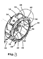
- An alternative impeller or radial impeller 210 is in FIG. 3 and comprises a circular disk-shaped support disk 212, a plurality of the same pitch on the support disk 212 fixed main blades 214 and provided with vanes 216 support or support ring 218 which is spaced from the support plate 212 fixed to the main blades 214.
- the support disk 212 is provided with a central recess 220, wherein a central axis of the recess 220 with a central axis 222 of the support disk 212 coincides.
- a radially inner region of the support plate 212 made of a metal sheet is provided with a hub which is to ensure a reliable attachment to a drive device, not shown, and a stable concentricity of the radial impeller 210, even at high peripheral speeds.
- the main blades 214 are rearwardly inclined to the support plate 212 in the present embodiment. That is, a circumferential velocity vector 224 tangentially formed on the outer periphery of the support disk 212 includes an acute angle with a largest surface 226 of the main blade 214, as shown symbolically in FIG FIG. 3 is shown.
- the guide vanes 216 are integral with the main blades 214, so that the largest surfaces of the vanes 216 at the same acute angle with the peripheral speed vector 224 include as the largest surfaces 226 of the main blades 214.
- the main blades 214 are each on one of the vanes 216th Angled opposite end portion at right angles, so that they can be firmly bonded, for example, by gluing or spot welding to the preferably made of metal support plate 212.
- the vanes 216 protrude orthogonally from the surface of the support disk 212.
- the support ring 218 is provided with slots, not shown, which are penetrated by the integral with the main blades 214 vanes 216.
- the guide vanes 216 are fixed to the support ring 218 by means of a material connection, in particular a soldered or welded connection, and protrude orthogonally therefrom.
- Radially outboard end faces of the main blades 214 and vanes 216 in the present embodiment of the radial impeller are oriented orthogonal to a largest surface 230 of the support disk 212.
- Radially inner end faces 232 of the main blades 214 are curved and thus aligned only substantially orthogonal to the largest surface 230 of the support disc 212.
- the support ring 218 is in the present embodiment according to the FIG. 3 formed in one piece from a face ring 234 and a radially inwardly adjoining, konusmantelabsacrificingsformigen a nozzle-providing and thus a second flow guide performing suction port 236.
- the guide vanes 216 are dimensioned such that they extend from the radially outer edge 238 of the face ring 234 to the radially inner edge 240 of the face ring 234.
- the inner edge 242 of the suction mouth 236 limits the intake cross section of the radial impeller 210.
Landscapes
- Engineering & Computer Science (AREA)
- Chemical & Material Sciences (AREA)
- Combustion & Propulsion (AREA)
- Mechanical Engineering (AREA)
- General Engineering & Computer Science (AREA)
- Structures Of Non-Positive Displacement Pumps (AREA)
- Baking, Grill, Roasting (AREA)
Description
- Die vorliegende Erfindung betrifft ein Gargerät mit einem Innenraum, einer Gebläseeinrichtung und einer Strömungsleitvorrichtung, die zumindest ein Lüfterrad in einem Innenraum des Gargeräts zum Zirkulieren von Atmosphäre aufweist, umfassend zumindest ein erstes Strömungsleitglied zur Unterteilung des Innenraums in einen Druckraum mit dem Lüfterrad und einen Garraum, wobei das erste Strömungsleitglied zumindest eine Einsaugöffnung zum Einsaugen von Atmosphäre aus dem Garraum in den Druckraum im Bereich des Lüfterrads und zumindest eine Ausblasöffnung zum Ausblasen von Atmosphäre aus dem Druckraum in den Garraum im Betrieb des Lüfterrads freilässt, und zumindest ein zweites Strömungsleitglied, an der Gebläseeinrichtung befestigtes oder mit der Gebläseeinrichtung ausgeformtes im Bereich der Einsaugöffnung des ersten Strömungsleitglieds zur Verbesserung der Strömung aus dem Garraum in den Druckraum durch Erzwingung einer axialen Hauptströmung im Einsaugbereich der Gebläseeinrichtung, wobei jedes zweite Strömungsleitglied eine Düsenfunktion erfüllt, sich von der Gebläseeinrichtung bis in den Garraum hineinerstreckt und den Rand der Einsaugöffnung des ersten Strömungsleitglieds überragt oder übergreift.
- Im Stand der Technik sind zahlreiche Maßnahmen zur Optimierung einer Strömung in dem Innenraum eines Gargeräts bekannt. Meist kommt dabei ein erstes Strömungsleitglied in Form eines Luftleitblechs zwischen einem Garraum und einem Gebläseraum bzw. Druckraum zum Einsatz, das eine mittige Einsaugöffnung aufweist und Ausblasöffnungen zur Wandung des Innenraums hin freilässt, so dass ein im Druckraum angeordnetes Lüfterrad Atmosphäre aus dem Garraum durch die Einsaugöffnung einsaugen und über die Ausblasöffnungen ausblasen kann. Beispielsweise die
DE 203 14 818 UI beschäftigt sich mit einem gezielten Ausblasen von Atmosphäre aus dem Druckraum in den Garraum über spezielle angeordnete Ausblasöffnungen im ersten Strömungsleitglied. Ebenfalls mit Ausblasöffnungen eines ersten Strömungsleitgliedes beschäftigt sich die nicht vorveröffentlichteDE 10 2007 023 767 , wobei dort bewegbare Elemente in Ausblasöffnungen angeordnet sein sollen, die sich in Abhängigkeit von dem Druckverlauf im Garraum bewegen. Einen anderen Ansatz findet man beispielsweise in derDE 203 09 268 UI durch Einsatz zweiter Strömungsleitglieder im Gebläseraum, durch die ein Abriss von Wirbeln beim Durchgang durch eine Ausblasöffnung zwischen dem Druckraum und dem Garraum erzwungen werden soll, so dass sich Wirbel im Garraum ausbreiten. Zweite Strömungsleitglieder zur Erzwingung einer homogenen Strömung im Garraum sind auch in derDE 203 12 031 UI offenbart. - Eine weitere Strömungsleitvorrichtung ist beispielsweise der
DE 10 2004 004 393 B4 zu entnehmen, bei der ein erstes Strömungsleitglied in einem mit einem zweiten Strömungsleitglied im Bereich seiner Einsaugöffnung ausgeführt. Genauer gesagt ist der Rand des ersten Strömungsleitglieds in Form eines Luftleitblechs im Bereich seiner Einsaugöffnung zur Bildung einer strömungsführenden Düse umgebogen ist. Diese Düse stellt eine Ansaugdüse dar und soll der Verbesserung des Einsaugens von Atmosphäre aus einem Garraum in einen Gebläseraum eines Gargeräts dienen. Nachteilig ist jedoch hieran, dass stets ein Spalt zwischen einem sich rotierenden Lüfterrad im Druckraum einerseits und der Ansaugdüse am Luftleitblech andererseits zur Vermeidung von Beschädigungen vorhanden sein muss. Dieser Spalt ist toleranzbedingt insbesondere bei Gargeräten der Großküche groß genug, um es Atmosphäre aus dem Druckraum zu erlauben, direkt in den Einsaugbereich des Lüfterrades zu strömen, also nicht über eine Ausblasöffnung in den Garraum und über die Einsaugöffnung des Luftleitblechs in den Einsaugbereich des Lüfterrads geführt zu werden, so dass es zu einem Kurzschluss mit der aus dem Garraum durch die Einsaugöffnung des Luftleitblechs einströmenden Atmosphäre kommt. Aus diesem Grunde wird diese durch den Spalt hindurchtretende Strömung auch Kurzschlussströmung genannt und tritt in einer sehr sensiblen Stelle im Einsaugbereich des Lüfterrades auf, nämlich im Umlenkbereich einer Hauptströmung aus dem Garraum in den Druckraum, genauer gesagt dort, wo eine Umlenkung von einer radialen Richtung in eine axiale Richtung der Hauptströmung stattfindet. Somit verläuft die Kurzschlussströmung quer zur Hauptströmung im Einsaugbereich des Lüfterrads, so dass sie die Hauptströmung einengt und selbst ein Ablösen sowie Verwirbeln der Hauptströmung zur Folge haben kann, was insgesamt zu einer Reduzierung des Wirkungsgrades der Zirkulation von Garraumatmosphäre durch das Lüfterrad führt. - Strömungsleitvorrichtungen für Gargeräte sind auch sowohl in der
EP 1 767 869 A2 als auch der DT 25 19 604 beschrieben, wobei in beiden Fällen ein erstes Strömungsleitglied sich zumindest bis zur Einsaugöffnung eines Lüfterrades ausbreitet, im Falle der DT 25 19 604 selbst in die Einsaugöffnung hineinerstreckt, während das zweite Strömungsleitglied in Form einer Außenkontur des Lüfterrades bereitgestellt ist. DieGB 1414546 - Bei einem gattungsgemäßen Gargerät gemäß der
DE 34 28 330 A1 bewirkt ein Gebläse eine Durchströmung eines Garraums mit Heißluft, wobei ein Teil der vom Gebläse angesaugten Luft zu einer Heizung und von dort durch einen Rückführkanal wieder zum Gebläse zurückgeführt wird. Im Bereich der Mündung dieses Rückführkanals laufen Schaufeln des Gebläses vorbei, welche die durch den Rückführkanal zugeführte Luft und gegebenenfalls auch einen Teil der von den Schaufeln aus dem Garraum angesaugten Luft in radialer Richtung abschleudern. - Aufgabe der vorliegenden Erfindung ist es, das gattungsgemäße Gargerät mit Strömungsleitvorrichtung derart weiterzuentwickeln, dass der Wirkungsgrad einer Zirkulation innerhalb des Innenraums des Gargeräts verbessert wird.
- Diese Aufgabe wird erfindungsgemäß dadurch gelöst, dass sich das erste Strömungsleitglied bis in jedes zweite Strömungsleitglied ausbreitet.
- Dabei ist bevorzugt, dass in dem Fall, in dem die Gebläseeinrichtung zumindest einen Radiallüfter umfasst, der eine Vielzahl von an einer Halteeinrichtung, insbesondere in Form eines Stützrings, angebrachten und konzentrisch zu einer antreibbaren Welle angeordneten Schaufeln aufweist, das zweite Strömungsleitglied an der Welle, der Halteeinrichtung, insbesondere dem Stützring, und/oder zumindest einer Schaufel, befestigt oder damit ausgeformt ist.
- Erfindungsgemäß kann dabei wiederum vorgesehen sein, dass das zweite Strömungsleitglied eine Ringform umfasst, insbesondere bei Anbringung an der Halteeinrichtung oder Anformung an der Halteeinrichtung.
- Mit der Erfindung wird auch vorgeschlagen, dass jedes zweite Strömungsleitglied sich im Druckraum bis in den Druckbereich des Lüfterrads erstreckt.
- Des Weiteren kann vorgesehen sein, dass jedes zweite Strömungsleitglied eine derartige Querschnittsform aufweist, dass eine Strömung aus dem Garraum in den Druckraum möglichst weit im Druckraum sich erst von der axialen Hauptströmung ablöst, wobei vorzugsweise ein im Wesentlichen hakenförmiger Querschnitt oder, insbesondere asymmetrisch, U förmiger Querschnitt mit einem verlängerten freien Ende des zweiten Strömungsleitglied im Druckraum ausgeformt ist.
- Zudem wird erfindungsgemäß vorgeschlagen, dass das erste Strömungsleitglied an einer Wandung des Innenraums angebracht oder anbringbar ist.
- Weiterentwicklungen der Erfindung können auch gekennzeichnet sein durch ein drittes Strömungsleitglied im Druckraum, das insbesondere einen sich vom Lüfterrad des Radiallüfters radial nach außen konisch erweiternden Ausblasbereich des Radiallüfters begrenzt.
- Dabei kann vorgesehen sein, dass das dritte Strömungsleitglied an dem ersten Strömungsleitglied angebracht oder zusammen mit demselben ausgeformt ist.
- Alternativ dazu kann vorgesehen sein, dass das dritte Strömungsleitglied eine Verlängerung des zweiten Strömungsleitglieds, insbesondere an dem freien Ende des zweiten Strömungsleitglieds im Druckraum, darstellt.
- Erfindungsgemäß wird zudem vorgeschlagen, dass das erste Strömungsleitglied, das zweite Strömungsleitglied und/oder das dritte Strömungsleitglied jeweils aus zumindest einem Stanz-Biegeteil und/oder Blech ausgeformt und/oder lösbar befestigt und/oder zumindest teilweise oder bereichsweise bewegbar ist bzw. sind.
- Ferner kann vorgesehen sein, dass das Ende des zweiten Strömungsleitglieds im Druckraum sich in eine Ausnehmung in dem ersten und/oder dritten Strömungsleitglied erstreckt.
- Besonders vorteilhafte Ausführungsformen sind gekennzeichnet durch eine Vielzahl von vierten Strömungsleitgliedern, insbesondere ein viertes Strömungsleitglied pro Schaufel, wobei vorzugsweise jedes vierte Strömungsleitglied schaufelförmig und/oder als Schaufelfortsatz, sich am bevorzugtesten durch den Stützring hindurch erstreckend, ausgebildet ist.
- Die Erfindung schlägt auch eine Weiterentwicklung mit einer Heizeinrichtung zum Aufheizen von Atmosphäre in dem Garraum vor.
- Dabei kann vorgesehen sein, dass das erste Strömungsleitglied, das zweite Strömungsleitglied und/oder das dritte Strömungsleitglied zumindest teilweise oder bereichsweise bewegbar ist bzw. sind, vorzugsweise über eine Steuer- oder Regeleinrichtung in Wirkverbindung mit der Heizeinrichtung, der Gebläseeinrichtung, einer Dampfzufuhreinrichtung, einer Dampfabfuhreinrichtung, einer Kühleinrichtung, einer Energiespeichereinrichtung, einer Mikrowellenquelle, einer Gaszufuhreinrichtung, einer Gasabfuhreinrichtung, einer Sensiereinrichtung und/oder einer Reinigungseinrichtung.
- Schließlich wird noch vorgeschlagen, dass eine, insbesondere gitterartige, Abschirmung zumindest des zweiten Strömungsleitglieds im Garraum, die insbesondere an dem ersten Strömungsleitglied, vorzugsweise lösbar, befestigt oder befestigbar ist.
- Der Erfindung liegt somit die überraschende Erkenntnis zugrunde, dass einerseits zumindest ein erstes stationäres Strömungsleitglied, beispielsweise in Form eines üblichen Luftleitblechs, in einem Innenraum eines Gargeräts zum Einsatz kommt, um den Innenraum in einen Druckraum und einen Garraum zu trennen, wobei das erste Strömungsleitglied zwischen dem Druckraum und dem Garraum eine zentrale Einsaugöffnung sowie zumindest eine randseitige Ausblasöffnung freilässt und an der Wandung des Innenraums befestigt ist, während andererseits zumindest ein zweites Strömungsleitglied zum Einsatz kommt, das die Funktion einer Düse erfüllt, die sich von einem Lüfterrad im Druckraum, an demselben angebracht oder mit demselben ausgeformt, durch die Einsaugöffnung des ersten Strömungsleitgliedes hindurch erstreckt, so dass also das zweite Strömungsleitglied sich mit dem Lüfterrad dreht. Besonders vorteilhaft ist die Düse, insbesondere ringförmig, an einem Stützring für Schaufeln eines Radiallüfters angebracht oder aus einer Vielzahl von Schaufelfortsätze ausgebildet. Auf jeden Fall wird durch die mit dem Lüfterrad rotierende Düse eine radiale Strömung im Einsaugbereich des Lüfterrads und somit eine Kurzschlussströmung vermieden. Dies steigert die Effizienz des Lüfterrads und reduziert die Empfindlichkeit des kompletten Gargeräts auf Maßtoleranzen.
- Da Radiallüfter prinzipbedingt relativ kompakt sind und eine hohe Effizienz aufweisen, kommen sie bevorzugt mit einer erfindungsgemäßen Strömungsleitvorrichtung zum Einsatz. Der Hochdruckbereich (die Druckseite des Gebläses) und der Ansaugbereich (die Saugseite des Gebläses) eines Radiallüfters liegen nämlich relativ nah aneinander, so dass durch die Düse am Radiallüfter eine erhebliche Steigerung der Lüfterleistung bzw. Reduzierung der Aufnahmeleistung des Lüftermotors vorliegt.
- Wenn die Düse und die Schaufeln des Radiallüfters auf einer gemeinsamen Welle befestigt sind, erübrigt sich auch die Notwendigkeit ein separates Gebläsegehäuse. Luftleitblech und die Düse bilden zusammen mit einer gegenüber dem Luftleitblech angeordneten Wandung des Innenraums quasi ein Gebläsegehäuse. Dennoch ist es bevorzugt, eine Abschirmung über den Einsaugbereich des Radiallüfters im Garraum zur Vermeidung einer Verletzung vorzusehen, vorzugsweise angebracht an dem ersten Strömungsleitglied.
- Durch die Bemaßung und Geometrie der Düse lassen sich weitere Vorteile bewirken, nämlich zur gezielte Strömungsführung. Erstreckt sich die Düse einerseits im Druckraum bis in den Bereich, in dem die Schaufeln des Radiallüfters eine Druckerhöhung bewirken, so reduziert sich die Menge an Kurzschlussströmung weiter. Wenn die Düse sich andererseits bis in den Garraum erstreckt, so wird eine Wirbelbildung im Einsaugbereich des Radiallüfters reduziert.
- Bevorzugt ist es erfindungsgemäß, dass noch ein drittes Strömungsleitglied zum Einsatz kommt, durch das sichergestellt ist, dass im Ausblasbereich des Radiallüfters der Druckraum einen sich von der Drehachse des Radiallüfters radial nach außen erweiternden Raum aufweist, so dass das dritte Luftleitglied als Diffuser wirkt und das Auftreten von Kurzschlussströmungen weiter reduziert. Das dritte Strömungsleitglied kann zusammen mit dem ersten Strömungsleitglied ausgeführt sein.
- Weitere Merkmale und Vorteile der Erfindung ergeben sich aus der nachfolgenden Beschreibung zweier Ausführungsbeispiele anhand schematischer Zeichnungen. Dabei zeigt:
- Fig. 1
- eine Teil-Querschnittsansicht eines erfindungsgemäßen Gargeräts;
- Fig. 2
- eine Detailansicht A von
Figur 1 ; und - Fig. 3
- eine perspektivische Ansicht eines alternativen Lüfterrads für ein erfindungsgemäßes Gargerät.
- Ein erfindungsgemäßes Gargerät umfasst, wie in
Fig. 1 gezeigt, einen Innenraum 1, in dem sich ein Lüfterrad 2 in Form eines Radiallüfterrads befindet. Das Lüfterrad 2 ist auf eine von einem nicht gezeigten Motor außerhalb des Innenraums 1 antreibbare Welle 3 montiert. Würde sich der Motor alternativerweise innerhalb des Innenraums 1 befinden, wären Kühlmaßnahmen erforderlich. - Obwohl im Prinzip auch ein Axialgebläse verwendet werden könnte, hat ein Radialgebläse den Vorteil, dass in Rotation versetzte Atmosphäre, insbesondere Garraumatmosphäre, nicht auf eine Rückwand 4 des Innenraums 1 aufprallt, sondern im Lüfterrad 2 bereits umgelenkt wird. Dadurch ist die Anordnung kompakt und weist eine hohe Effizienz auf.
- Das Lüfterrad 2 saugt Atmosphäre zentral an, nämlich aus einem Einsaugbereich 5, siehe die Einsaugströmung E in
Figur 1 , und bläst sie radial aus, nämlich in einen Ausblasbereich 6, siehe die Ausblasströmung A inFigur 1 . Im Prinzip wäre auch eine Variante denkbar, in der die Atmosphäre in umgekehrter Richtung strömt, wobei dann Maßnahmen vorgesehen werden müssen, um eine Querströmung im Ausblasbereich 6 zu vermeiden. - Der Innenraum 1 wird von einem ersten Strömungsleitglied, beispielsweise in Form eines Luftleitblechs 7, zumindest teilweise in einen Garraum 8 und einen Druckraum 9 unterteilt. Das Luftleitblech 7 ist zum Beispiel über (nicht dargestellte) Stege an den Wänden des Innenraums 1 lösbar sowie arretierbar angebracht. Das Lüfterrad 2 ist separat im Gargerät montiert, und zwar mit dem Lüfterrad 2 im Druckraum 9, ohne feste Verbindung zu dem Luftleitblech 7. Das Luftleitblech 7 lässt an seinen äußeren Rändern Spalte 10a für die Ausblasströmung A offen und weist eine zentrale Öffnung 10b für die Einsaugströmung E auf, die auf den Einlassbereich 5 abgestimmt ist.
- Durch die Zirkulation der Atmosphäre im Innenraum 1 ist ein vergleichsmäßigter Wärmeeintrag in Gargut (nicht gezeigt) im Garraum 8 nach Aufheizung der Atmosphäre über ein nicht gezeigtes Heizmittel möglich, und zwar sowohl in konventionellen Öfen, wie Back- und Bratöfen, beispielsweise auch mit Dampffunktion und/oder Mikrowellenbeaufschlagung. Das Heizmittel kann beispielsweise in Form von Heizwendeln um das Lüfterrad 2 ausgebildet sein.
- Um die Umlenkung von Atmosphäre aus dem Einsaugbereich 5 in das Lüfterrad 2 hinein zu verbessern und zur Vermeidung von Quer- und Gegenströmungen, die zu Kurschlussströmungen führen können, die die Leistung des Gebläses beeinträchtigen könnten, ist eine Düse 11 als zweites Strömungsleitglied im Bereich der Öffnung 10b des Luftleitglieds 7 am Lüfterrad 2 vorgesehen. Die Düse 11 führt dabei Atmosphäre hauptsächlich in axialer Richtung in das Lüfterrad 2 hinein. Wie schematisch in
Figur 1 dargestellt, wird Atmosphäre vor allem im radialen Randbereich des Einsaugbereichs 5 des Lüfterrads 2 in Form einer Hauptströmung H angesaugt, weshalb die Düse 11 nicht nur auf den Einsaugbereich 5 in ihrer Anordnung und Bemaßung abgestimmt ist, sondern auch an die Öffnung 10b des Luftleitblechs 7. - Das Lüfterrad 2 umfasst Schaufeln 12. Das sich in axialer Richtung betrachtet an der Einsaugseite des Lüfterrads 2 befindende Ende einer jeden Schaufel 12 wird dabei von einer ringförmigen Wand 13 eines Stützrings, der Teil des Lüfterrads 2 und somit rotierend auf der Welle 3 befestigt ist, begrenzt. Die Düse 11 ist in dem in
Figur 1 gezeigten Ausführungsbeispiel an diesen Stützring bzw. an diese ringförmige Wand 13 fest angebracht und weist selbst auch eine Ringform auf, so dass eine durchgehende Abschottung des Druckraums 9 gegenüber der Hauptströmung H vorliegt. Es werden dadurch Quer- und Gegenströmungen im Bereich der Hauptströmung H weitgehend vermieden. - Bei einer alternativen Ausführungsform kann die Düse auf andere Weise an dem Lüfterrad zwecks Vermeidung besagter Quer- und Gegenströmungen befestigt sein. Es wäre im Prinzip beispielsweise möglich, die Düse, entweder rotierend oder nicht rotierend, auf einer Verlängerung der Welle zu montieren, was allerdings eine genaue Einhaltung von Toleranzgrenzen in dem Abstand zwischen dem Lüfterrad und der Düse, der möglichst klein gehalten werden sollte, fordern würde. Dies wäre nicht vorteilhaft. Vorteilhaft ist hingegen, die Düse in Form von weiteren Schaufeln, die sich von der Wand 13 in Richtung des Luftleitblechs 7 erstrecken oder als Fortsätze der Schaufeln 12, die sich durch die Wand 13 in Richtung des Luftleitblechs 7 erstrecken, auszuformen. Diese Ausführungsform vergrößert den Einsaugbereich 5 des Lüfterrads 2 bei gleichbleibendem Bauraum. Des Weiteren wird dann die Förderleistung des Lüfterrads 2 erhöht, so dass die Gargeschwindigkeit erhöht oder die Leistung des Lüfterantriebs verringert werden kann. Gleichzeitig verbessert sich das Auswurfverhalten des Lüfterrads 2, indem der durchströmte Querschnitt beim Verlassen des Lüfterrads 2 größer wird. Durch den größeren durchströmten Querschnitt kann aber auch das Heizmittel effektiver umströmt werden, was zu einem verbesserten Wärmeeintrag in Gargut führt.
- Ob nun die Düse 11 ringförmig oder in Form einer Vielzahl von Schaufelfortsätzen an der Stützringwand 13 ausgebildet ist, ändert nichts daran, dass die Öffnung 10b des Luftleitblechs 7 relativ frei gewählt werden kann und das Gargerät zumindest betreffend die Strömungsleitglieder 7, 11 nicht mehr in hohem Maße toleranzabhängig ist.
- Mit Bezug auf
Figur 2 wird nun im Detail der Verlauf der diversen Strömungen zwischen dem Druckraum 9 und dem Garraum 8 beschrieben: - In dem Bereich zwischen dem im Betrieb rotierenden Lüfterrad 2 und dem Luftleitblech 7 befindet sich ein Spalt 14. Der Spalt 14 ist dabei so bemaßt, dass gewährleistet ist, dass das rotierende Lüfterrad 2 samt Düse 11 auf keinen Fall das nicht rotierende Luftleitblech 7 streift. Die Abmessungen des Spalts 14 sind gewissermaßen abhängig von Fertigungstoleranzen sowohl des Luftleitblechs 7, bzw. dessen Öffnung 10b, als auch des Lüfterrads 2, bzw. dessen Schaufeln 12, sowie der Wand 13 und der Düse 11. Der Spalt 14 eröffnet eine Verbindung zwischen Bereichen mit großen Druckunterschieden, was zu einer sich aus der Ausblasströmung A abspaltenden Gegenströmung G aus dem Druckraum 9 in den Garraum 8, genauer gesagt vom Ausblasbereich 6 des Lüfterrads 2 in dessen Einsaugbereich 5, führt. Damit diese Gegenströmung G zuerst in Richtung der Rotationsachse des Lüfterrads 2 radial im Druckraum 9, dann im wesentlichen axial im Bereich des Luftleitblechs 7 und schließlich radial nach außen im Garraum 8 verläuft, um in möglichst geringe Wechselwirkung mit der Hauptströmung H zu treten, also keine Kurzschlussströmung zu bilden, erstreckt sich die Düse 11 in axialer Richtung betrachtet bis mindestens an die Öffnung 10b im Luftleitblech 7. Um zu vermeiden, dass die Gegenströmung G gleich wieder in den Einsaugbereich 5 fließt, ragt die Düse 11 selbst durch die Öffnung 10b in den Garraum 8 hinein. Zudem wird die Gegenströmung G in radialer Richtung von der Einsaugströmung E weg abgelenkt, indem die Düse 11 sich zu dem Einsaugbereich 5 hin verbreitet. Der Radius des zum Garraum 8 abgewandten Randes 15 der Düse 11 ist hingegen größer als der Radius der Öffnung 10b im Luftleitblech 7. Dadurch wird der Strömungswiderstand des Spalts 14 erhöht sowie zum einen die Stärke einer Wirbelbildung und zum anderen das Volumen der Gegenströmung G reduziert.
- Um zu vermeiden, dass die rotierende Düse 11 sich im Garraum 8 befindende Gegenstände, wie einen Hordengestellwagen oder dergleichen, berührt, ist eine luftdurchlässige Abschirmung 18 vorgesehen. Diese Abschirmung 18, zum Beispiel in Form eines Gitters, ist an dem Luftleitblech 7 befestigt und dient auch dem Schutz vor Verletzungen, indem sie einen Eingriff in das Lüfterrad 2 vermeidet.
- Eine Wirbelbildung kann in einer erfindungsgemäßen Ausführungsform weiter verringert werden durch Einsatz eines als Diffuser fungierenden dritten Strömungsleitglieds in Form eines weiteren Luftleitblechs 17. Das weitere Luftleitblech 17 kann auf das erste Luftleitblech 7 aufmontiert oder in einem mit dem ersten Luftleitblech 7 ausgeformt sein. Auf jeden Fall vergrößert sich ein Abstand B1 zwischen dem weiteren Luftleitblech 17 und der Rückwand 4 des Druckraums 9 radial nach außen relativ zur Längsachse der Welle 3 (Rotationsachse des Lüfterrads) zumindest im Ausblasbereich 6. Die aus dem Lüfterrad 2 ausströmende Ausblasströmung A gelangt so ohne große Querschnittsänderungen in den Ausblasbereich 6 und strömt weiter zu den Spalten 10a zwischen dem ersten Luftblech 7 und der Innenraumwandung, wobei aufgrund der Strömungsführungen Wirbelbildungen vermieden und Kurzschlussströmungen reduziert werden.
- Die Erfindung ist nicht beschränkt auf die im Einzelnen dargestellten Ausführungsformen, sondern kann innerhalb des Schutzbereichs der angehängten Ansprüche variiert werden. Zum Beispiel kann der Rand 15 der Düse 11 in eine von einer Verzweigung des ersten und/oder zweiten Luftleitblechs 7, 9 gebildeten Ausnehmung zum Zwecke einer weiteren Erhöhung des von der Gegenströmung G empfundenen Widerstands hineinragen.
- Ein alternatives Lüfterrad beziehungsweise Radiallaufrad 210 ist in
Figur 3 dargestellt und umfasst eine kreisscheibenförmig ausgebildete Tragscheibe 212, mehrere in gleicher Teilung an der Tragscheibe 212 festgelegte Hauptschaufeln 214 und einen mit Leitschaufeln 216 versehenen Stütz- beziehungsweise Tragring 218, der beabstandet zur Tragscheibe 212 an den Hauptschaufeln 214 festgelegt ist. - Die Tragscheibe 212 ist mit einer zentralen Ausnehmung 220 versehen, wobei eine Mittelachse der Ausnehmung 220 mit einer Mittelachse 222 der Tragscheibe 212 zusammenfällt. In einem radial innenliegenden Bereich ist die aus einer Blechplatine hergestellte Tragscheibe 212 mit einer Nabe versehen, die eine zuverlässige Befestigung an einer nicht dargestellten Antriebseinrichtung und einen stabilen Rundlauf des Radiallaufrads 210 auch bei hohen Umfangsgeschwindigkeiten gewährleisten soll. Die Hauptschaufeln 214 sind bei der vorliegenden Ausführungsform rückwärts geneigt an der Tragscheibe 212 angeordnet. Das heißt, dass ein tangential am Außenumfang der Tragscheibe 212 angetragener Umfangsgeschwindigkeitsvektor 224 einen spitzen Winkel mit einer größten Oberfläche 226 der Hauptschaufel 214 einschließt, wie dies symbolisch in der
Figur 3 dargestellt ist. - Bei der in
Figur 3 dargestellten Ausführungsform des Radiallaufrads 210 sind die Leitschaufeln 216 einstückig mit den Hauptschaufeln 214 ausgeführt, so dass größte Oberflächen der Leitschaufeln 216 den gleichen spitzen Winkel mit dem Umfangsgeschwindigkeitsvektor 224 einschließen wie größte Oberflächen 226 der Hauptschaufeln 214. Die Hauptschaufeln 214 sind jeweils an einem den Leitschaufeln 216 entgegengesetzten Endbereich rechtwinkelig abgewinkelt, so dass sie beispielsweise durch Kleben oder Punktschweißen an der vorzugsweise aus Metall hergestellten Tragscheibe 212 stoffschlüssig festgelegt werden können. Die Leitschaufeln 216 ragen orthogonal von der Oberfläche der Tragscheibe 212 ab. - Der Tragring 218 ist mit nicht näher dargestellten Schlitzen versehen, die von den mit den Hauptschaufeln 214 einstückig verbundenen Leitschaufeln 216 durchsetzt werden. Die Leitschaufeln 216 sind mittels einer stoffschlüssigen Verbindung, insbesondere einer Löt- oder Schweißverbindung, an dem Tragring 218 festgelegt und ragen von diesem orthogonal ab. Radial außenliegende Stirnseiten der Hauptschaufeln 214 und der Leitschaufeln 216 sind bei der vorliegenden Ausführungsform des Radiallaufrads orthogonal zu einer größten Oberfläche 230 der Tragscheibe 212 ausgerichtet. Radial innenliegende Stirnseiten 232 der Hauptschaufeln 214 sind gekrümmt ausgebildet und somit nur im Wesentlichen orthogonal zur größten Oberfläche 230 der Tragscheibe 212 ausgerichtet.
- Der Tragring 218 ist bei der vorliegenden Ausführungsform gemäß der
Figur 3 einstückig aus einem Planring 234 und einem sich radial innenliegend anschließenden, konusmantelabschnittsformigen eine Düse bereitstellenden und somit ein zweites Strömungsleitglied darstellender Saugmund 236 ausgebildet. Die Leitschaufeln 216 sind so dimensioniert, dass sie sich vom radial außenliegenden Rand 238 des Planrings 234 bis zum radial innenliegenden Rand 240 des Planrings 234 erstrecken. Der innere Rand 242 des Saugmunds 236 begrenzt den Ansaugquerschnitt des Radiallaufrads 210. - Vom Radiallaufrad 210 angesaugte, durch die Einsaugöffnung eines ersten Strömungsleitglieds gemäß den
Figuren 1 und2 strömende Garraumatmosphäre wird entweder durch den Saugmund 236, also das zweite Strömungsleitglied, geleitet und von den Hauptschaufeln 214 in radialer Richtung nach außen beschleunigt oder tritt in einen zwischen dem Saugmund 236 und dem ersten Strömungsleitglied verbleibenden Spalt ein. In dem Spalt sorgen die Leitschaufeln 216 dafür, dass unerwünschte Turbulenzen, die den Wirkungsgrad einer mit dem Radiallaufrad 210 ausgestatteten Lüfteranordnung reduzieren könnten, vermieden werden. Die Leitschaufeln 216 stellen somit weitere Strömungsleitglieder (vierte Strömungsleitglieder) zur Steigerung der Effizienz des Radiallaufrads 210 dar. -
- 1
- Innenraum
- 2
- Lüfterrad
- 3
- Welle
- 4
- Rückwand
- 5
- Einsaugbereich
- 6
- Ausblasbereich
- 7
- Luftleitblech
- 8
- Garraum
- 9
- Druckraum
- 10a
- Spalt
- 10b
- Öffnung
- 11
- Düse
- 12
- Schaufel
- 13
- Stützringwand
- 14
- Spalt
- 15
- Rand
- 16
- Abschirmung
- 17
- Luftleitblech
- 210
- Radiallaufrad
- 212
- Tragscheibe
- 214
- Hauptschaufel
- 216
- Leitschaufel
- 218
- Tragring
- 220
- Ausnehmung
- 222
- Mittelachse
- 224
- Umfangsgeschwindigkeitsvektor
- 226
- Oberfläche
- 230
- Oberfläche
- 232
- Stirnseite
- 234
- Planring
- 236
- Saugmund/Düse
- 238
- radial außenliegender Rand
- 240
- radial innenliegender Rand
- 242
- innerer Rand
- H
- Hauptströmung
- G
- Gegenströmung
- E
- Einsagströmung
- A
- Ausblasströmung
- B1
- Abstand
Claims (15)
- Gargerät mit einem Innenraum (1) einer Strömungsleitvorrichtung (7, 11, 17, 216) und einer Gebläseeinrichtung (2, 3, 210), die zumindest ein Lüfterrad (2, 210) in dem Innenraum (1) des Gargeräts zum Zirkulieren von Atmosphäre aufweist, umfassend zumindest ein erstes Strömungsleitglied (7) zur Unterteilung des Innenraums (1) in einen Druckraum (9) mit dem Lüfterrad (2) und einen Garraum (8), wobei das erste Strömungsleitglied (7) zumindest eine Einsaugöffnung (10b) zum Einsaugen von Atmosphäre aus dem Garraum (8) in den Druckraum (9) im Betrieb des Lüfterrads (2, 210) und zumindest eine Ausblasöffnung (10a) zum Ausblasen von Atmosphäre aus dem Druckraum (9) in den Garraum (8) im Betrieb des Lüfterrads (2, 210) freilässt, und zumindest ein zweites, an der Gebläseeinrichtung (2, 3, 210) befestigtes oder mit der Gebläseeinrichtung (2, 3, 210) ausgeformtes Strömungsleitglied (11, 236) im Bereich der Einsaugöffnung (10b) des ersten Strömungsleitglieds (7) zur Verbesserung der Strömung aus dem Garraum (8) in den Druckraum (9) durch Erzwingung einer axialen Hauptströmung H im Einsaugbereich (5) der Gebläseeinrichtung (2, 3, 210), wobei jedes zweite Strömungsleitglied (11, 236) eine Düsenfunktion erfüllt und sich von der Gebläseeinrichtung (2, 3, 210) bis in den Garraum (8) hinein erstreckt und den Rand der Einsaugöffnung (10b) des ersten Strömungsleitglieds (7) überragt oder übergreift, dadurch gekennzeichnet, dass sich das erste Strömungsleitglied (7) bis in jedes zweite Strömungsleitglied (11) ausbreitet.
- Gargerät nach Anspruch 1, dadurch gekennzeichnet, dass in dem Fall, in dem die Gebläseeinrichtung (2, 3) zumindest einen Radiallüfter umfasst, der eine Vielzahl von an einer Halteeinrichtung, insbesondere in Form eines Stützrings (13), angebrachten und konzentrisch zu einer antreibbaren Welle (3) angeordneten Schaufeln (12) aufweist, das zweite Strömungsleitglied (11) an der Welle (3), der Halteeinrichtung, insbesondere dem Stützring (13), und/oder zumindest einer Schaufel (12), befestigt oder damit ausgeformt ist.
- Gargerät nach Anspruch 2, dadurch gekennzeichnet, dass
das zweite Stromungsleitglied (11) eine Ringform umfaBt, insbesondere bei Anbringung an der Halteeinrichtung oder Anforrnung an der Halteeinrichtung. - Gargerät nach einem der vorangehenden Ansprüche, dadurch gekennzeichnet, dass jedes zweite Strömungsleitglied (11) sich im Druckraum (9) bis in den Druckbereich des Lüfterrads (2) erstreckt.
- Gargerät nach einem der vorangehenden Ansprüche, dadurch gekennzeichnet, dass jedes zweite Strömungsleitglied (11) eine derartige Querschnittsform aufweist, dass eine Strömung aus dem Garraum (8) in den Druckraum (9) möglichst weit im Druckraum (9) sich erst von der axialen Hauptströmung H ablöst, wobei
vorzugsweise ein im Wesentlichen hakenfömiger Querschnilt oder, insbesondere asymmetrisch, U förmiger Querschnitt mit einem verlängerten freien Ende (15) des zweiten Strömungsleitglieds (11) im Druckraum (9) ausgeformt ist. - Gargerät nach einem der vorangehenden Ansprüche, dadurch gekennzeichnet, dass
das erste Strömungsleitglied (7) an einer Wandung des Innenraums (1) angebracht oder anbringbar ist. - Gargerät nach einem der vorangehenden Ansprüche, gekennzeichnet durch ein drittes Strömungsleitglied (17) im Druckraum (9), das insbesondere einen sich vom Lüfterrad (2) des Radiallüfters radial nach außen konisch erweiternden Ausblasbereich (6) des Radiallüfters begrenzt.
- Gargerät nach Anspruch 7, dadurch gekennzeichnet, dass
das dritte Strömungsleitglied (17) an dem ersten Strömungsleitglied (7) angebracht oder zusammen mit demselben ausgeformt ist. - Gargerät nach Anspruch 8, dadurch gekennzeichnet, dass
das dritte Strömungsleitglied eine Verlängerung des zweiten Strömungsleitglieds, insbesondere an dem freien Ende des zweiten Strömungsleitglieds im Druckraum, darstellt. - Gargerät nach einem der vorangehenden Ansprüche, dadurch gekennzeichnet, dass
das erste Strömungsleitglied (7), das zweite Strömungsleitglied (11) und/oder das dritte Strömungsleitglied (17) jeweils aus zumindest einem Stanz-Biegeteil und/oder Blech ausgeformt und/oder lösbar befestigt und/oder zumindest teilweise oder bereichsweise bewegbar ist bzw. sind. - Gargerät nach einem der vorangehenden Ansprüche, dadurch gekennzeichnet, dass
das Ende (15) des zweiten Strömungsleitglieds (11) im Druckraum (9) sich in eine Ausnehmung in dem ersten und/oder dritten Strömungsleitglied (7, 17) erstreckt. - Gargerät nach einem der vorangehenden Ansprüche, gekennzeichnet durch
eine Vielzahl von vierten Strömungsleitgliedern (216), insbesondere ein viertes Strömungsleitglied (216) pro Schaufel (214), wobei vorzugsweise jedes vierte Strömungsleitglied (216) schaufelförmig und/oder als Schaufelfortsatz, sich am bevorzugtesten durch den Stützring (218) hindurch ersteckend, ausgebildet ist. - Gargerät nach einem der vorangehenden Ansprüche, gekennzeichne durch eine Heizeinrichtung zum Aufheizen von Atmosphäre in dem Garraum (8).
- Gargerät nach Anspruch 13, dadurch gekennzeichnet, dass
das erste Strömungsleitglied (7), das zweite Strömungsleitglied (11) und/oder das dritte Strömungsleitglied (17) zumindest teilweise oder bereichsweise bewegbar ist bzw. sind, vorzugsweise über eine Steuer- oder Regeleinrichtung in Wirkverbindung mit der Heizeinrichtung, der Gebläseeinrichtung (2, 3), einer Dampfzufuhreinrichtung, einer Dampfabfuhreinrichtung, einer Kühleinrichtung, einer Energiespeichereinrichtung, einer Mikrowellenquelle, einer Gaszufuhreinrichtung, einer Gasabfuhreinrichtung, einer Sensiereinrichtung und/oder einer Reinigungseinrichtung. - Gargerät nach Anspruch 13 oder 14, gekennzeichnet durch
eine, insbesondere gitterartige, Abschirmung (16) zumindest des zweiten Strömungsleitglieds (11) im Garraum (8), die insbesondere an dem ersten Strömungsleitglied (7), vorzugsweise lösbar, befestigt oder befestigbar ist.
Applications Claiming Priority (2)
| Application Number | Priority Date | Filing Date | Title |
|---|---|---|---|
| DE102008053145A DE102008053145A1 (de) | 2008-10-24 | 2008-10-24 | Strömungsleitvorrichtung für ein Gargerät |
| PCT/EP2009/064020 WO2010046491A2 (de) | 2008-10-24 | 2009-10-23 | Strömungsleitvorrichtung für ein gargerät |
Publications (2)
| Publication Number | Publication Date |
|---|---|
| EP2350533A2 EP2350533A2 (de) | 2011-08-03 |
| EP2350533B1 true EP2350533B1 (de) | 2013-07-31 |
Family
ID=42055066
Family Applications (1)
| Application Number | Title | Priority Date | Filing Date |
|---|---|---|---|
| EP09748082.6A Active EP2350533B1 (de) | 2008-10-24 | 2009-10-23 | Gargerät mit einer strömungsleitvorrichtung |
Country Status (8)
| Country | Link |
|---|---|
| US (1) | US9557066B2 (de) |
| EP (1) | EP2350533B1 (de) |
| JP (1) | JP2012506528A (de) |
| CN (1) | CN102203511A (de) |
| BR (1) | BRPI0919855B1 (de) |
| DE (1) | DE102008053145A1 (de) |
| DK (1) | DK2350533T3 (de) |
| WO (1) | WO2010046491A2 (de) |
Families Citing this family (8)
| Publication number | Priority date | Publication date | Assignee | Title |
|---|---|---|---|---|
| DE102010037284A1 (de) | 2010-09-02 | 2012-03-08 | Rational Ag | Verfahren zur Durchführung eines Garprozesses |
| KR101671109B1 (ko) * | 2015-04-30 | 2016-10-31 | 엘지전자 주식회사 | 조리기기 |
| TW201731430A (zh) * | 2016-02-25 | 2017-09-16 | Panasonic Ip Man Co Ltd | 感應加熱調理器及烤盤 |
| DE102016204833B4 (de) * | 2016-03-23 | 2017-11-16 | Convotherm-Elektrogeräte Gmbh | Gewerbliches Gargerät |
| US12329314B2 (en) | 2016-06-15 | 2025-06-17 | Koninklijke Philips N.V. | Air-frying cooker |
| DE102018209581A1 (de) * | 2018-06-14 | 2019-12-19 | BSH Hausgeräte GmbH | Gargerät |
| CN109931291A (zh) * | 2019-05-08 | 2019-06-25 | 泛仕达机电股份有限公司 | 一种旋转式集流器 |
| EP4001773A1 (de) * | 2020-11-20 | 2022-05-25 | BSH Hausgeräte GmbH | Garraumeinsatz mit integriertem heizelement und austauschbarer energieabgabeeinheit, anordnung, gargerät und verfahren |
Family Cites Families (50)
| Publication number | Priority date | Publication date | Assignee | Title |
|---|---|---|---|---|
| US2039429A (en) * | 1931-04-16 | 1936-05-05 | Lydon Timothy | Oven and the like with heat circulating means therefor |
| NL7117236A (de) * | 1971-12-16 | 1973-06-19 | ||
| GB1414546A (en) | 1973-01-16 | 1975-11-19 | Cannon Ind Ltd | Gas-fired cooking ovens |
| DE2400845A1 (de) * | 1974-01-09 | 1975-07-17 | Burger Eisenwerke Ag | Geraet zur waermebehandlung von lebensmitteln und speisen |
| IT1024113B (it) * | 1974-05-18 | 1978-06-20 | Zanussi Grandi | Forro a convenzione forzata |
| US4108139A (en) * | 1976-04-12 | 1978-08-22 | The Tappan Company | Convection oven |
| JPS5620656A (en) | 1979-07-30 | 1981-02-26 | Asahi Chemical Ind | Substrate fabric for simulated leather |
| USRE31765E (en) * | 1979-11-27 | 1984-12-11 | Sunset Ltd. | Counter-top oven |
| US4430541A (en) * | 1981-01-14 | 1984-02-07 | Raytheon Company | Combination microwave gas convection oven |
| JPS57134399U (de) * | 1981-02-18 | 1982-08-21 | ||
| US4395233A (en) * | 1981-06-22 | 1983-07-26 | G. S. Blodgett Co., Inc. | Dual flow heating apparatus |
| JPS58194747U (ja) * | 1982-06-18 | 1983-12-24 | 大畠 隆 | 加工食品保管庫 |
| US4484561A (en) * | 1982-09-14 | 1984-11-27 | Crescent Metal Products, Inc. | Gas convection oven |
| AT378668B (de) | 1983-08-04 | 1985-09-10 | Koenig Helmut | Backofen |
| US4635610A (en) * | 1985-04-17 | 1987-01-13 | Sharp Kabushiki Kaisha | Hot air circulating oven range using shape memory alloy |
| US4780596A (en) * | 1986-05-15 | 1988-10-25 | Kabushiki Kaisha Toshiba | Hot-air circulation cooking oven |
| US4908488A (en) * | 1988-07-22 | 1990-03-13 | Samsung Electronics Co., Ltd. | Fixing device of a heating member in a combined microwave and convection cooking apparatus |
| IT1227212B (it) * | 1988-09-23 | 1991-03-27 | Eurodomestici Ind Riunite | Forno elettrico, a doppia camera ad irraggiamento uniforme, particolarmente per la preparazione di torte e dolci in generale |
| CA2024203C (en) * | 1989-09-22 | 2002-07-30 | Donald P. Smith | Balanced air return convection oven |
| US4963091A (en) * | 1989-10-23 | 1990-10-16 | Surface Combustion, Inc. | Method and apparatus for effecting convective heat transfer in a cylindrical, industrial heat treat furnace |
| FR2660418A1 (fr) * | 1990-04-03 | 1991-10-04 | Bonnet Sa | Four de cuisson d'aliments. |
| US5228385A (en) * | 1992-03-03 | 1993-07-20 | Friedrich Metal Products Co., Inc. | Convection oven for bakery goods |
| CA2123640A1 (en) * | 1993-05-17 | 1994-11-18 | Thomas A. Berger | Airflow measuring centrifugal fan |
| US5909533A (en) * | 1998-04-06 | 1999-06-01 | Dacor, Inc. | Electric cooking oven with infrared gas broiler |
| US6521870B2 (en) * | 2001-01-11 | 2003-02-18 | General Electric Company | Thermal/convection oven including halogen lamps |
| JP3970626B2 (ja) | 2002-02-07 | 2007-09-05 | シャープ株式会社 | 加熱調理器 |
| FR2837067A1 (fr) * | 2002-03-12 | 2003-09-19 | Eurofours Sa | Four ventile |
| JP3827303B2 (ja) * | 2002-03-12 | 2006-09-27 | 松下電器産業株式会社 | 蒸気発生機能付き高周波加熱装置 |
| DE20309268U1 (de) | 2003-06-12 | 2004-06-09 | Rational Ag | Gargeräte mit Luftleitgliedern |
| DE20312031U1 (de) | 2003-08-04 | 2004-06-17 | Rational Ag | Gargeräte mit Luftleitgliedern |
| US7297904B2 (en) * | 2003-09-18 | 2007-11-20 | Premark Feg Llc | Convection oven and related air flow system |
| DE20314818U1 (de) | 2003-09-24 | 2004-06-09 | Rational Ag | Gargerät mit Luftleitglied |
| US6933472B1 (en) * | 2003-11-14 | 2005-08-23 | Blodgett Holdings, Inc. | Electric convection oven |
| TR200603298T1 (tr) * | 2003-12-30 | 2006-12-21 | Arçeli̇k Anoni̇m Şi̇rketi̇ | Bir pişirici cihaz |
| DE102004004393B3 (de) * | 2004-01-29 | 2005-05-25 | Rational Ag | Gargerät, Luftleitglied, Haltevorrichtung und Verfahren zum Reinigen eines Gargeräts |
| JP3835804B2 (ja) * | 2004-02-10 | 2006-10-18 | 松下電器産業株式会社 | 加熱調理器及び加熱調理方法 |
| KR20060064312A (ko) * | 2004-12-08 | 2006-06-13 | 삼성전자주식회사 | 가열조리장치 |
| KR20060070910A (ko) * | 2004-12-21 | 2006-06-26 | 삼성전자주식회사 | 전기오븐 |
| EP1674798A1 (de) * | 2004-12-27 | 2006-06-28 | Samsung Electronics Co., Ltd. | Gargerät und Garmethode |
| CN101203714A (zh) * | 2005-04-22 | 2008-06-18 | 范松皇家油墨厂 | 在制备区内具有均匀热气流的烘箱 |
| ITMO20050238A1 (it) * | 2005-09-23 | 2007-03-24 | Angelo Grandi Cucine Societa P | Apparato di cottura |
| US20090314276A1 (en) * | 2006-07-10 | 2009-12-24 | Panasonic Corporation | Heating cooking apparatus |
| DE102007023767B4 (de) | 2007-05-22 | 2011-01-05 | Rational Ag | Gargerät mit dynamischer Luftführung |
| EP2015610B1 (de) * | 2007-07-09 | 2015-09-09 | Samsung Electronics Co., Ltd. | Konvektionserwärmungseinheit und Kochgerät damit |
| KR101388339B1 (ko) * | 2007-08-14 | 2014-04-22 | 엘지전자 주식회사 | 전기오븐 |
| KR101185557B1 (ko) * | 2007-10-09 | 2012-09-24 | 삼성전자주식회사 | 조리기기 및 그 제어방법 |
| KR101412149B1 (ko) * | 2007-10-29 | 2014-07-02 | 엘지전자 주식회사 | 조리 기기 |
| DE102007061285A1 (de) * | 2007-12-19 | 2009-06-25 | BSH Bosch und Siemens Hausgeräte GmbH | Heißluft- oder Umluftofen |
| US20090178665A1 (en) * | 2008-01-15 | 2009-07-16 | Weber Matthew A | Rotisserie with Directional Baffles |
| US8752538B2 (en) * | 2008-01-15 | 2014-06-17 | Premark Feg L.L.C. | Rotisserie oven with lifting wash arm |
-
2008
- 2008-10-24 DE DE102008053145A patent/DE102008053145A1/de not_active Withdrawn
-
2009
- 2009-10-23 JP JP2011532655A patent/JP2012506528A/ja active Pending
- 2009-10-23 US US13/125,793 patent/US9557066B2/en active Active
- 2009-10-23 BR BRPI0919855A patent/BRPI0919855B1/pt active IP Right Grant
- 2009-10-23 DK DK09748082.6T patent/DK2350533T3/da active
- 2009-10-23 WO PCT/EP2009/064020 patent/WO2010046491A2/de not_active Ceased
- 2009-10-23 CN CN2009801422012A patent/CN102203511A/zh active Pending
- 2009-10-23 EP EP09748082.6A patent/EP2350533B1/de active Active
Also Published As
| Publication number | Publication date |
|---|---|
| JP2012506528A (ja) | 2012-03-15 |
| DK2350533T3 (da) | 2013-10-07 |
| WO2010046491A2 (de) | 2010-04-29 |
| WO2010046491A4 (de) | 2010-09-16 |
| CN102203511A (zh) | 2011-09-28 |
| BRPI0919855A2 (pt) | 2015-12-15 |
| US20110253123A1 (en) | 2011-10-20 |
| US9557066B2 (en) | 2017-01-31 |
| BRPI0919855B1 (pt) | 2019-12-31 |
| DE102008053145A1 (de) | 2010-04-29 |
| EP2350533A2 (de) | 2011-08-03 |
| WO2010046491A3 (de) | 2010-07-29 |
Similar Documents
| Publication | Publication Date | Title |
|---|---|---|
| EP2350533A2 (de) | Strömungsleitvorrichtung für ein gargerät | |
| DE68903433T2 (de) | Zarge fuer motorkuehlluefter. | |
| EP2978976B1 (de) | Getriebe mit einer welle | |
| DE69620286T2 (de) | Kühlungsanlage für eine Brennkraftmaschine | |
| EP1446583B1 (de) | Lüfterrad für elektrische maschinen | |
| DE102013109577A1 (de) | Gebläsemodul für einen Wärmetauscher | |
| EP2870382B1 (de) | Getriebe mit einer welle und darauf angebrachtem lüfter in einer lüfterhaube | |
| EP2196679A2 (de) | Radialgebläserad | |
| DE69127832T2 (de) | Staubsauger mit Gebläserad und Diffusor | |
| EP1970635B1 (de) | Heissluft-Backofen mit Umlenkblechen | |
| EP0833110B1 (de) | Backofen mit Gebläse | |
| EP1530682B1 (de) | Lüfterrad mit integrierter fettabscheidung, insbesondere für ein gargerät | |
| EP1458982B1 (de) | Lüftervorrichtung | |
| DE3907308A1 (de) | Leitrad fuer ein geblaese | |
| DE102009028125A1 (de) | Eintrittsgeometrie für halbaxiale Lüfterräder | |
| EP0615069B1 (de) | Lüfterrad | |
| DE9016767U1 (de) | Dunstabzugshaube | |
| EP4314567B1 (de) | Elektromotor mit einer kühlanordnung | |
| EP3421806B1 (de) | Gebläse | |
| EP2930372B1 (de) | Trommelläufer-laufrad mit wuchttaschen | |
| DE102005012815A1 (de) | Gehäuse, Laufrad und Radialgebläse mit einem Gehäuse und einem Laufrad | |
| EP1046822B1 (de) | Gebläse mit einem Spiralgehäuse | |
| DE69012995T2 (de) | Lüfter für eine elektrisch betriebene maschine. | |
| DE102005027460A1 (de) | Wärme ableitende Vorrichtung | |
| EP1582750B1 (de) | Gehäuse und Radialgebläse mit einem Gehäuse und einem Laufrad |
Legal Events
| Date | Code | Title | Description |
|---|---|---|---|
| PUAI | Public reference made under article 153(3) epc to a published international application that has entered the european phase |
Free format text: ORIGINAL CODE: 0009012 |
|
| 17P | Request for examination filed |
Effective date: 20110519 |
|
| AK | Designated contracting states |
Kind code of ref document: A2 Designated state(s): AT BE BG CH CY CZ DE DK EE ES FI FR GB GR HR HU IE IS IT LI LT LU LV MC MK MT NL NO PL PT RO SE SI SK SM TR |
|
| RIN1 | Information on inventor provided before grant (corrected) |
Inventor name: RING, LEONHARD Inventor name: HERNER, MICHAEL Inventor name: PAINTNER, ALO Inventor name: HYLLA, JOACHIM, J. Inventor name: KURTH, ROBERT Inventor name: WITT, OLIVER Inventor name: CLAUSSEN, ERNST Inventor name: SCHREINER, THOMAS Inventor name: XIA, YINGAN |
|
| DAX | Request for extension of the european patent (deleted) | ||
| GRAP | Despatch of communication of intention to grant a patent |
Free format text: ORIGINAL CODE: EPIDOSNIGR1 |
|
| INTG | Intention to grant announced |
Effective date: 20130417 |
|
| GRAS | Grant fee paid |
Free format text: ORIGINAL CODE: EPIDOSNIGR3 |
|
| GRAA | (expected) grant |
Free format text: ORIGINAL CODE: 0009210 |
|
| AK | Designated contracting states |
Kind code of ref document: B1 Designated state(s): AT BE BG CH CY CZ DE DK EE ES FI FR GB GR HR HU IE IS IT LI LT LU LV MC MK MT NL NO PL PT RO SE SI SK SM TR |
|
| REG | Reference to a national code |
Ref country code: GB Ref legal event code: FG4D Free format text: NOT ENGLISH Ref country code: CH Ref legal event code: EP |
|
| REG | Reference to a national code |
Ref country code: AT Ref legal event code: REF Ref document number: 624884 Country of ref document: AT Kind code of ref document: T Effective date: 20130815 |
|
| REG | Reference to a national code |
Ref country code: IE Ref legal event code: FG4D Free format text: LANGUAGE OF EP DOCUMENT: GERMAN |
|
| REG | Reference to a national code |
Ref country code: DE Ref legal event code: R096 Ref document number: 502009007682 Country of ref document: DE Effective date: 20130926 |
|
| REG | Reference to a national code |
Ref country code: DK Ref legal event code: T3 Effective date: 20130930 Ref country code: DK Ref legal event code: T3 |
|
| REG | Reference to a national code |
Ref country code: NL Ref legal event code: VDEP Effective date: 20130731 |
|
| REG | Reference to a national code |
Ref country code: LT Ref legal event code: MG4D |
|
| PG25 | Lapsed in a contracting state [announced via postgrant information from national office to epo] |
Ref country code: NO Free format text: LAPSE BECAUSE OF FAILURE TO SUBMIT A TRANSLATION OF THE DESCRIPTION OR TO PAY THE FEE WITHIN THE PRESCRIBED TIME-LIMIT Effective date: 20131031 Ref country code: HR Free format text: LAPSE BECAUSE OF FAILURE TO SUBMIT A TRANSLATION OF THE DESCRIPTION OR TO PAY THE FEE WITHIN THE PRESCRIBED TIME-LIMIT Effective date: 20130731 Ref country code: PT Free format text: LAPSE BECAUSE OF FAILURE TO SUBMIT A TRANSLATION OF THE DESCRIPTION OR TO PAY THE FEE WITHIN THE PRESCRIBED TIME-LIMIT Effective date: 20131202 Ref country code: SE Free format text: LAPSE BECAUSE OF FAILURE TO SUBMIT A TRANSLATION OF THE DESCRIPTION OR TO PAY THE FEE WITHIN THE PRESCRIBED TIME-LIMIT Effective date: 20130731 Ref country code: IS Free format text: LAPSE BECAUSE OF FAILURE TO SUBMIT A TRANSLATION OF THE DESCRIPTION OR TO PAY THE FEE WITHIN THE PRESCRIBED TIME-LIMIT Effective date: 20131130 Ref country code: CY Free format text: LAPSE BECAUSE OF FAILURE TO SUBMIT A TRANSLATION OF THE DESCRIPTION OR TO PAY THE FEE WITHIN THE PRESCRIBED TIME-LIMIT Effective date: 20130626 Ref country code: LT Free format text: LAPSE BECAUSE OF FAILURE TO SUBMIT A TRANSLATION OF THE DESCRIPTION OR TO PAY THE FEE WITHIN THE PRESCRIBED TIME-LIMIT Effective date: 20130731 |
|
| PG25 | Lapsed in a contracting state [announced via postgrant information from national office to epo] |
Ref country code: LV Free format text: LAPSE BECAUSE OF FAILURE TO SUBMIT A TRANSLATION OF THE DESCRIPTION OR TO PAY THE FEE WITHIN THE PRESCRIBED TIME-LIMIT Effective date: 20130731 Ref country code: SI Free format text: LAPSE BECAUSE OF FAILURE TO SUBMIT A TRANSLATION OF THE DESCRIPTION OR TO PAY THE FEE WITHIN THE PRESCRIBED TIME-LIMIT Effective date: 20130731 Ref country code: FI Free format text: LAPSE BECAUSE OF FAILURE TO SUBMIT A TRANSLATION OF THE DESCRIPTION OR TO PAY THE FEE WITHIN THE PRESCRIBED TIME-LIMIT Effective date: 20130731 Ref country code: NL Free format text: LAPSE BECAUSE OF FAILURE TO SUBMIT A TRANSLATION OF THE DESCRIPTION OR TO PAY THE FEE WITHIN THE PRESCRIBED TIME-LIMIT Effective date: 20130731 Ref country code: GR Free format text: LAPSE BECAUSE OF FAILURE TO SUBMIT A TRANSLATION OF THE DESCRIPTION OR TO PAY THE FEE WITHIN THE PRESCRIBED TIME-LIMIT Effective date: 20131101 Ref country code: PL Free format text: LAPSE BECAUSE OF FAILURE TO SUBMIT A TRANSLATION OF THE DESCRIPTION OR TO PAY THE FEE WITHIN THE PRESCRIBED TIME-LIMIT Effective date: 20130731 |
|
| PG25 | Lapsed in a contracting state [announced via postgrant information from national office to epo] |
Ref country code: CY Free format text: LAPSE BECAUSE OF FAILURE TO SUBMIT A TRANSLATION OF THE DESCRIPTION OR TO PAY THE FEE WITHIN THE PRESCRIBED TIME-LIMIT Effective date: 20130731 |
|
| BERE | Be: lapsed |
Owner name: RATIONAL A.G. Effective date: 20131031 |
|
| PG25 | Lapsed in a contracting state [announced via postgrant information from national office to epo] |
Ref country code: EE Free format text: LAPSE BECAUSE OF FAILURE TO SUBMIT A TRANSLATION OF THE DESCRIPTION OR TO PAY THE FEE WITHIN THE PRESCRIBED TIME-LIMIT Effective date: 20130731 Ref country code: SK Free format text: LAPSE BECAUSE OF FAILURE TO SUBMIT A TRANSLATION OF THE DESCRIPTION OR TO PAY THE FEE WITHIN THE PRESCRIBED TIME-LIMIT Effective date: 20130731 Ref country code: RO Free format text: LAPSE BECAUSE OF FAILURE TO SUBMIT A TRANSLATION OF THE DESCRIPTION OR TO PAY THE FEE WITHIN THE PRESCRIBED TIME-LIMIT Effective date: 20130731 |
|
| PG25 | Lapsed in a contracting state [announced via postgrant information from national office to epo] |
Ref country code: MC Free format text: LAPSE BECAUSE OF FAILURE TO SUBMIT A TRANSLATION OF THE DESCRIPTION OR TO PAY THE FEE WITHIN THE PRESCRIBED TIME-LIMIT Effective date: 20130731 Ref country code: ES Free format text: LAPSE BECAUSE OF FAILURE TO SUBMIT A TRANSLATION OF THE DESCRIPTION OR TO PAY THE FEE WITHIN THE PRESCRIBED TIME-LIMIT Effective date: 20130731 |
|
| REG | Reference to a national code |
Ref country code: CH Ref legal event code: PL |
|
| PLBE | No opposition filed within time limit |
Free format text: ORIGINAL CODE: 0009261 |
|
| STAA | Information on the status of an ep patent application or granted ep patent |
Free format text: STATUS: NO OPPOSITION FILED WITHIN TIME LIMIT |
|
| GBPC | Gb: european patent ceased through non-payment of renewal fee |
Effective date: 20131031 |
|
| 26N | No opposition filed |
Effective date: 20140502 |
|
| REG | Reference to a national code |
Ref country code: IE Ref legal event code: MM4A |
|
| PG25 | Lapsed in a contracting state [announced via postgrant information from national office to epo] |
Ref country code: LI Free format text: LAPSE BECAUSE OF NON-PAYMENT OF DUE FEES Effective date: 20131031 Ref country code: CH Free format text: LAPSE BECAUSE OF NON-PAYMENT OF DUE FEES Effective date: 20131031 Ref country code: GB Free format text: LAPSE BECAUSE OF NON-PAYMENT OF DUE FEES Effective date: 20131031 |
|
| REG | Reference to a national code |
Ref country code: DE Ref legal event code: R097 Ref document number: 502009007682 Country of ref document: DE Effective date: 20140502 |
|
| PG25 | Lapsed in a contracting state [announced via postgrant information from national office to epo] |
Ref country code: BE Free format text: LAPSE BECAUSE OF NON-PAYMENT OF DUE FEES Effective date: 20131031 |
|
| PG25 | Lapsed in a contracting state [announced via postgrant information from national office to epo] |
Ref country code: IE Free format text: LAPSE BECAUSE OF NON-PAYMENT OF DUE FEES Effective date: 20131023 |
|
| PG25 | Lapsed in a contracting state [announced via postgrant information from national office to epo] |
Ref country code: SM Free format text: LAPSE BECAUSE OF FAILURE TO SUBMIT A TRANSLATION OF THE DESCRIPTION OR TO PAY THE FEE WITHIN THE PRESCRIBED TIME-LIMIT Effective date: 20130731 |
|
| PG25 | Lapsed in a contracting state [announced via postgrant information from national office to epo] |
Ref country code: TR Free format text: LAPSE BECAUSE OF FAILURE TO SUBMIT A TRANSLATION OF THE DESCRIPTION OR TO PAY THE FEE WITHIN THE PRESCRIBED TIME-LIMIT Effective date: 20130731 |
|
| PG25 | Lapsed in a contracting state [announced via postgrant information from national office to epo] |
Ref country code: HU Free format text: LAPSE BECAUSE OF FAILURE TO SUBMIT A TRANSLATION OF THE DESCRIPTION OR TO PAY THE FEE WITHIN THE PRESCRIBED TIME-LIMIT; INVALID AB INITIO Effective date: 20091023 Ref country code: LU Free format text: LAPSE BECAUSE OF NON-PAYMENT OF DUE FEES Effective date: 20131023 Ref country code: MK Free format text: LAPSE BECAUSE OF FAILURE TO SUBMIT A TRANSLATION OF THE DESCRIPTION OR TO PAY THE FEE WITHIN THE PRESCRIBED TIME-LIMIT Effective date: 20130731 Ref country code: BG Free format text: LAPSE BECAUSE OF FAILURE TO SUBMIT A TRANSLATION OF THE DESCRIPTION OR TO PAY THE FEE WITHIN THE PRESCRIBED TIME-LIMIT Effective date: 20130731 |
|
| PG25 | Lapsed in a contracting state [announced via postgrant information from national office to epo] |
Ref country code: MT Free format text: LAPSE BECAUSE OF FAILURE TO SUBMIT A TRANSLATION OF THE DESCRIPTION OR TO PAY THE FEE WITHIN THE PRESCRIBED TIME-LIMIT Effective date: 20130731 |
|
| REG | Reference to a national code |
Ref country code: FR Ref legal event code: PLFP Year of fee payment: 7 |
|
| REG | Reference to a national code |
Ref country code: AT Ref legal event code: MM01 Ref document number: 624884 Country of ref document: AT Kind code of ref document: T Effective date: 20141023 |
|
| PG25 | Lapsed in a contracting state [announced via postgrant information from national office to epo] |
Ref country code: AT Free format text: LAPSE BECAUSE OF NON-PAYMENT OF DUE FEES Effective date: 20141023 |
|
| REG | Reference to a national code |
Ref country code: FR Ref legal event code: PLFP Year of fee payment: 8 |
|
| REG | Reference to a national code |
Ref country code: FR Ref legal event code: PLFP Year of fee payment: 9 |
|
| REG | Reference to a national code |
Ref country code: FR Ref legal event code: PLFP Year of fee payment: 10 |
|
| PGFP | Annual fee paid to national office [announced via postgrant information from national office to epo] |
Ref country code: DK Payment date: 20191022 Year of fee payment: 11 |
|
| REG | Reference to a national code |
Ref country code: DK Ref legal event code: EBP Effective date: 20201031 |
|
| PG25 | Lapsed in a contracting state [announced via postgrant information from national office to epo] |
Ref country code: DK Free format text: LAPSE BECAUSE OF NON-PAYMENT OF DUE FEES Effective date: 20201031 |
|
| P01 | Opt-out of the competence of the unified patent court (upc) registered |
Effective date: 20230619 |
|
| PGFP | Annual fee paid to national office [announced via postgrant information from national office to epo] |
Ref country code: CZ Payment date: 20231011 Year of fee payment: 15 |
|
| PG25 | Lapsed in a contracting state [announced via postgrant information from national office to epo] |
Ref country code: CZ Free format text: LAPSE BECAUSE OF NON-PAYMENT OF DUE FEES Effective date: 20241023 |
|
| PGFP | Annual fee paid to national office [announced via postgrant information from national office to epo] |
Ref country code: DE Payment date: 20251020 Year of fee payment: 17 |
|
| PGFP | Annual fee paid to national office [announced via postgrant information from national office to epo] |
Ref country code: IT Payment date: 20251031 Year of fee payment: 17 |
|
| PGFP | Annual fee paid to national office [announced via postgrant information from national office to epo] |
Ref country code: FR Payment date: 20251027 Year of fee payment: 17 |