EP2978976B1 - Getriebe mit einer welle - Google Patents
Getriebe mit einer welle Download PDFInfo
- Publication number
- EP2978976B1 EP2978976B1 EP14705476.1A EP14705476A EP2978976B1 EP 2978976 B1 EP2978976 B1 EP 2978976B1 EP 14705476 A EP14705476 A EP 14705476A EP 2978976 B1 EP2978976 B1 EP 2978976B1
- Authority
- EP
- European Patent Office
- Prior art keywords
- fan
- gear unit
- fan impeller
- separating plate
- air
- Prior art date
- Legal status (The legal status is an assumption and is not a legal conclusion. Google has not performed a legal analysis and makes no representation as to the accuracy of the status listed.)
- Active
Links
- 230000000694 effects Effects 0.000 claims description 9
- 239000003570 air Substances 0.000 description 61
- 230000005540 biological transmission Effects 0.000 description 38
- 230000008901 benefit Effects 0.000 description 15
- 238000005192 partition Methods 0.000 description 6
- 238000004519 manufacturing process Methods 0.000 description 4
- 230000008878 coupling Effects 0.000 description 3
- 238000010168 coupling process Methods 0.000 description 3
- 238000005859 coupling reaction Methods 0.000 description 3
- 239000002184 metal Substances 0.000 description 3
- 229910000831 Steel Inorganic materials 0.000 description 2
- 238000001816 cooling Methods 0.000 description 2
- 239000010959 steel Substances 0.000 description 2
- 230000032258 transport Effects 0.000 description 2
- 239000012080 ambient air Substances 0.000 description 1
- 238000005452 bending Methods 0.000 description 1
- 239000012530 fluid Substances 0.000 description 1
- 230000004941 influx Effects 0.000 description 1
- 238000004064 recycling Methods 0.000 description 1
- 230000009467 reduction Effects 0.000 description 1
- 238000009827 uniform distribution Methods 0.000 description 1
Images


Classifications
-
- F—MECHANICAL ENGINEERING; LIGHTING; HEATING; WEAPONS; BLASTING
- F04—POSITIVE - DISPLACEMENT MACHINES FOR LIQUIDS; PUMPS FOR LIQUIDS OR ELASTIC FLUIDS
- F04D—NON-POSITIVE-DISPLACEMENT PUMPS
- F04D29/00—Details, component parts, or accessories
- F04D29/58—Cooling; Heating; Diminishing heat transfer
- F04D29/5806—Cooling the drive system
-
- F—MECHANICAL ENGINEERING; LIGHTING; HEATING; WEAPONS; BLASTING
- F04—POSITIVE - DISPLACEMENT MACHINES FOR LIQUIDS; PUMPS FOR LIQUIDS OR ELASTIC FLUIDS
- F04D—NON-POSITIVE-DISPLACEMENT PUMPS
- F04D17/00—Radial-flow pumps, e.g. centrifugal pumps; Helico-centrifugal pumps
- F04D17/06—Helico-centrifugal pumps
-
- F—MECHANICAL ENGINEERING; LIGHTING; HEATING; WEAPONS; BLASTING
- F04—POSITIVE - DISPLACEMENT MACHINES FOR LIQUIDS; PUMPS FOR LIQUIDS OR ELASTIC FLUIDS
- F04D—NON-POSITIVE-DISPLACEMENT PUMPS
- F04D17/00—Radial-flow pumps, e.g. centrifugal pumps; Helico-centrifugal pumps
- F04D17/08—Centrifugal pumps
-
- F—MECHANICAL ENGINEERING; LIGHTING; HEATING; WEAPONS; BLASTING
- F04—POSITIVE - DISPLACEMENT MACHINES FOR LIQUIDS; PUMPS FOR LIQUIDS OR ELASTIC FLUIDS
- F04D—NON-POSITIVE-DISPLACEMENT PUMPS
- F04D25/00—Pumping installations or systems
- F04D25/02—Units comprising pumps and their driving means
- F04D25/028—Units comprising pumps and their driving means the driving means being a planetary gear
-
- F—MECHANICAL ENGINEERING; LIGHTING; HEATING; WEAPONS; BLASTING
- F04—POSITIVE - DISPLACEMENT MACHINES FOR LIQUIDS; PUMPS FOR LIQUIDS OR ELASTIC FLUIDS
- F04D—NON-POSITIVE-DISPLACEMENT PUMPS
- F04D29/00—Details, component parts, or accessories
- F04D29/05—Shafts or bearings, or assemblies thereof, specially adapted for elastic fluid pumps
- F04D29/053—Shafts
-
- F—MECHANICAL ENGINEERING; LIGHTING; HEATING; WEAPONS; BLASTING
- F04—POSITIVE - DISPLACEMENT MACHINES FOR LIQUIDS; PUMPS FOR LIQUIDS OR ELASTIC FLUIDS
- F04D—NON-POSITIVE-DISPLACEMENT PUMPS
- F04D29/00—Details, component parts, or accessories
- F04D29/26—Rotors specially for elastic fluids
- F04D29/28—Rotors specially for elastic fluids for centrifugal or helico-centrifugal pumps for radial-flow or helico-centrifugal pumps
- F04D29/281—Rotors specially for elastic fluids for centrifugal or helico-centrifugal pumps for radial-flow or helico-centrifugal pumps for fans or blowers
-
- F—MECHANICAL ENGINEERING; LIGHTING; HEATING; WEAPONS; BLASTING
- F04—POSITIVE - DISPLACEMENT MACHINES FOR LIQUIDS; PUMPS FOR LIQUIDS OR ELASTIC FLUIDS
- F04D—NON-POSITIVE-DISPLACEMENT PUMPS
- F04D29/00—Details, component parts, or accessories
- F04D29/40—Casings; Connections of working fluid
- F04D29/42—Casings; Connections of working fluid for radial or helico-centrifugal pumps
- F04D29/4206—Casings; Connections of working fluid for radial or helico-centrifugal pumps especially adapted for elastic fluid pumps
-
- F—MECHANICAL ENGINEERING; LIGHTING; HEATING; WEAPONS; BLASTING
- F04—POSITIVE - DISPLACEMENT MACHINES FOR LIQUIDS; PUMPS FOR LIQUIDS OR ELASTIC FLUIDS
- F04D—NON-POSITIVE-DISPLACEMENT PUMPS
- F04D29/00—Details, component parts, or accessories
- F04D29/58—Cooling; Heating; Diminishing heat transfer
- F04D29/582—Cooling; Heating; Diminishing heat transfer specially adapted for elastic fluid pumps
-
- F—MECHANICAL ENGINEERING; LIGHTING; HEATING; WEAPONS; BLASTING
- F16—ENGINEERING ELEMENTS AND UNITS; GENERAL MEASURES FOR PRODUCING AND MAINTAINING EFFECTIVE FUNCTIONING OF MACHINES OR INSTALLATIONS; THERMAL INSULATION IN GENERAL
- F16H—GEARING
- F16H57/00—General details of gearing
- F16H57/04—Features relating to lubrication or cooling or heating
- F16H57/0412—Cooling or heating; Control of temperature
- F16H57/0415—Air cooling or ventilation; Heat exchangers; Thermal insulations
- F16H57/0416—Air cooling or ventilation
Definitions
- the invention relates to a transmission with a shaft.
- a transmission housing wherein a fan wheel is connected to a shaft and a fan cover has a radially inwardly extending sheet metal part having an opening.
- the invention is therefore the object of developing a transmission with a shaft in the most compact manner, so to enable as much power with the lowest possible volume.
- the object is achieved in the transmission with a shaft according to the features specified in claim 1.
- a fan wheel is rotatably connected to the shaft, wherein a fan cover is connected to the transmission housing, which at least partially surrounds the fan wheel, wherein a separating plate for separating the pressure space of the fan from the suction space of the fan is connected to the fan hood, wherein the separating plate has an air inlet opening for the fan wheel and is arranged on the axially remote from the transmission side of the fan wheel.
- the advantage here is that the pressure chamber is separated from the suction chamber by a simple thin and inexpensive metal sheet, especially steel.
- a simple thin and inexpensive metal sheet especially steel.
- the fan has a fan wheel, which has a first and a second cover disk, which are axially spaced from each other, wherein fan blades of the fan wheel are arranged between the cover disks, wherein the separating plate has an air inlet opening for the fan wheel and is arranged on the axially remote from the transmission side of a cover plate of the fan wheel.
- the advantage here is that the air is guided in channels of the fan wheel, wherein the channels are formed by the fan blades and the cover plates.
- the air inlet through the centrally located opening in the separating plate is executable such that the air is fed directly into the channels of the fan and as little turbulence and vortex losses occur in the access area.
- the opening in the cutting disc essentially corresponds to the opening diameter of the air inlet of the fan wheel facing the separating plate.
- the fan is a radial fan, in particular wherein the fan blades of the fan are circumferentially spaced irregularly.
- the advantage here is that an energy-efficient working fan is used, which has a low noise.
- the separating plate is detachably connected to the fan cover.
- the advantage here is that alternatively different sized fan wheels can be provided in the fan cowl by replacing the baffle.
- the fan cover and / or the gear housing is rectangular and or the outer diameter of the fan wheel is greater than the width of the transmission housing and / or is smaller than the height of the transmission housing.
- air baffles are arranged to prevent or reduce the swirl of the airflow flowing out of the fan cowl between the fan cowl and the gear housing, wherein the baffles are axially spaced from the fan, in particular with the distance h1.
- the advantage here is that as untwisted air flow exits the fan or at least from the fan cover surrounding the fan.
- the fan cowl is formed in the air outlet region as a nozzle, so that an outgoing air flow flows along the transmission housing.
- the advantage here is that the exit velocity can be increased.
- a cover plate is axially spaced from the separating plate, so that the admission of air takes place from the radial direction, in particular, wherein the cover plate has recesses for enabling additionally axially entering air flow.
- the fan cover in particular with a separating plate, designed as a stamped and bent part, in particular wherein the nozzle is designed by setting a fan hood edge in the air outlet region,
- the outer radius of the fan is greater than the width of the transmission and is smaller than the height of the transmission.
- the outer radius of the fan is smaller than the width of the transmission and smaller than the height of the transmission.
- the radius of the opening of the separating plate is designed to be correspondingly small, ie with the outer radius of the air inlet region of the fan wheel formed by the channels of the fan wheel.
- the air baffles extend radially from the gear housing to the fan cover. The advantage here is that a simple anti-twist effect can be achieved.
- the air baffles are each just shapeable and very thin-walled, so that a substantially pure radial extent is sufficient.
- the fan wheel has a first and a second cover plate, which are axially spaced from each other, wherein fan blades are arranged between the cover plates, so that channels are formed, wherein the channel cross-section from the radially inner inlet region on the fan to the radially outer outlet region on the fan increases monotonically, in particular wherein the inlet region takes place at an axial position, ie in particular the inlet area a radially and circumferentially extending surface and the outlet area surface itself is in the radial direction, in the circumferential direction and in the axial direction extending surface.
- the advantage here is that a diffuser effect is executable and still causes the fan a conveying effect.
- the air is transported on the one hand radially outward and on the other hand built up a high pressure.
- a high exit velocity can be achieved by means of the nozzle, which converts the pressure built up by the fan into a high one Exit speed.
- the radially outwardly directed airflow has an axial component because the exit area surface extends in all three directions. The exit area of the fan thus simplifies a deflection of the radially conveyed air flow in the axial direction, wherein the fan cover for complete deflection in the axial direction is additionally effective.
- At least one of the cover plates is conically shaped.
- a fan 5 is rotatably connected to the driving shaft 8 of the transmission 6.
- a fan cover 9 is arranged, which surrounds the fan 5.
- the transmission is designed as a bevel gear, which is why the driving shaft 8 is mounted in a Kegeltopfgekoruseteil 11, which is connected to the housing of the transmission 6.
- the fan 5 comprises a radial fan, the fan blades 7 extend radially, in particular only radially. Thus, a direction of rotation independent air transport is possible.
- the first cover plate 10 and the second cover plate 13 are thus axially spaced from each other.
- the Fan blades 7 cover the axial intermediate region between the first and second cover disks 10, 13.
- the fan cowl 9 has a separating plate 1, which extends radially and is arranged at an axial position, which is arranged on the side facing away from the transmission with conical-pot housing part 11.
- the separating plate 1 has a centrally disposed opening, so that the air is admitted from the axial direction. However, the opening in the separating plate 1 is made so small that the embedded air does not hit the outer edge of the fan.
- the inner diameter of the opening of the cutting disk 1 is smaller than the maximum outer diameter of the fan. 5
- the fan 5 Due to the arrangement of the fan 5 on the driving shaft of the transmission designed as a reduction gear, the fan 5 is arranged on the fastest rotating shaft, namely on the driving shaft 8.
- the fan cowl 9 deflects the air flow conveyed by the fan 5 from the radial to the axial direction.
- constriction generating means By means of constriction generating means, a nozzle 3 and thus an increased outlet velocity is achieved in the axial outlet region.
- the outlet openings of the fan cowl 9 are arranged on their side facing away from the drive side such that the exiting air flow flows along the transmission housing.
- the gearbox is made as in the plan view FIG. 3 can be seen, executed substantially cuboid, so that the front side has a substantially rectangular contour.
- the fan cowl 9 also has a rectangular shape, which is preferably substantially square and in particular has a larger cross-sectional area than the fan 5 and the gear housing, in particular in plan view FIG. 3 ,
- the maximum outer diameter of the fan 5 is greater than the width of the transmission housing but smaller than the height of the transmission housing. Likewise, the fan cover is wider than the width of the transmission housing.
- the outlet between Fan 5 and gear housing is therefore large, in particular, it corresponds approximately to the difference between the width of the fan cover 9 and the width of the transmission housing.
- the fan cowl 9 has radially aligned and extending air baffles 4.
- the angular momentum of the delivered air flow is reduced.
- Each of the air baffles extends from the fan cowl to the gearbox housing. Depending on the circumferential angle position of the respective air baffle 4, the radial extent is different. The baffles 4 thus act as anti-whirl plates for the exiting air flow.
- the diameter of the fan 5 is smaller than the height of the transmission housing.
- the first cover plate 10 is conically shaped with the cone tip removed.
- the opening thus provided is effective as an air inlet and has a diameter which is smaller than or equal to the diameter of the air inlet opening provided by the partition plate 1.
- the channel cross section Q2 increases from the inlet cross section Q1 until it reaches the outlet cross section Q3.
- the growth, ie the increase, of the cross section Q2 is monotonic.
- the fan works on the one hand as a diffuser, on the other hand, however, is a promotion effect in the radial direction by training as a radial fan. Thus, a relatively high pressure at relatively low flow rate is generated by the radial fan.
- the second cover plate 13 is preferably made flat, so it extends in the radial direction and in the circumferential direction.
- the air enters the area surrounded by the fan cowl 9 area from the radial direction, because the associated opening opens in the radial direction into the environment.
- the air entered is guided radially further inside and flows there in the opening region of the partition plate 1 axially into the fan 5 a.
- the radially outflowed from the fan 5 air flow is deflected by the fan cover 9.
- the outlet of the air flow takes place in the axial direction along the transmission housing.
- the constriction causes a nozzle effect and thus an increase in the flow velocity of the exiting air flow.
- the driving shaft 8 is connectable to a driving shaft of a gear driving electric motor.
- the axial region covered by the fan cowl 9 comprises the axial region covered by the fan blades 7 and at least partially also the axial region covered by the air guide plates 4.
- Fan cover 12 and separating plate 1 are integrally finished, in particular of a metal sheet, in particular sheet steel.
- a particularly simple and cost-effective production can be achieved by the production as a stamped and bent part.
- a two-piece design is advantageous, especially for small quantities.
- the fan cover has a rectangular cross-section.
- the normal of the cross-sectional area is aligned parallel to the axis of the driving shaft.
- the air baffles 4 are axially spaced from the fan 5.
- the fan blades 7 are not uniformly spaced in the circumferential direction, so that losses, in particular structure-borne noise and airborne sound losses, can be reduced. Preferably, nine fan blades 7 are present.
- the hub of the fan wheel is conical, wherein the circumference of the hub increases in the flow direction for the diversion of the air in the radial direction.
- FIG. 3 are shown in the circumferential direction six radially long extending air baffles 4 and two further, radially extending short baffles 40, which are arranged in the upper and in the lower region of the fan cowl 9.
- the pressure side and the suction side are thus separated by the separating plate 1.
- the arranged in the partition plate 1 opening for the air inlet is cut out circular, wherein the center of the circle lies on the imaginary axis of the driving shaft.
- the nozzle 3 is easily produced by employment of the trailing edge of the fan cover 9.
- the employment has an angle between 10 ° and 40 °.
- the cover plate 12 directs the air from radially outside to radially further inside.
- any attachment is providable on the axial end region of the driving shaft facing away from the fan 5. Because these axially extending away from the cover plate and the gearbox attachments have no significant effect on the air flow.
- the cover plate 12 allows the influx of cool ambient air from the radial direction. So even if the attachments have a hot surface, no air flow transports heat from the attachments in the fan.
- a coupling between the driving electric motor and the transmission, in particular the driving shaft of the transmission can be arranged.
- a fluid coupling arranged on the driving shaft 8 that is to say a hydraulically operating coupling which has a large extent in the radial direction, the access of cool air to the ventilator 5 is nevertheless effected by the cover plate 12.
- the cover plate 12 is connected via a Eingreifschgepatuseteil 14 with the fan cover 9.
- the Eingreifschgepatuseteil 14 has recesses which are so small that no human finger of an adult passes through, but are large enough to let in the air flow with the least possible resistance
- cover plate 12 allows a flow of air from all circumferential angular positions. In this case, a uniform distribution is achieved.
- the outflow cross section Q3 is preferably between 1.1 times and 1.3 times larger than the inflow cross section Q1.
- blade channel length L2 is between 0.3 times and 0.5 times the fan radius RL.
- the respective blade channel is delimited at least in the circumferential direction by the two respectively adjacent fan blades 7 and in the axial direction on the one hand by the first cover disk 10 and on the other hand by the second cover disk 13.
- the separating plate adjoins the fan wheel, wherein a spacing, so a gap is provided, wherein the gap width of the gap, in particular so covered by the gap radial gap range, less than 10%, in particular less than 5%, in particular less than 5% and greater than 0.1% of the outer diameter of the fan wheel.
- the fan 5 is executed differently than at FIG. 2 ,
- the first cover plate 10 is further radially inwardly extending and the fan 5 then further axially through the recess of the partition plate 1 protruding.
- the axial area covered by the fan 5 also covers the axial area of the separating plate 1.
- the smallest radial distance of the separating plate 1 is arranged within the Radialabstandsberiech covered by the fan 5, in particular of the first cover plate 10.
- the axial position of the separating plate 1 or the axial region covered by the separating plate 1 is arranged within the axial region covered by the fan 5, in particular by its first cover plate 10.
- the edge of the separating plate 1, which surrounds the air inlet opening provided by the separating plate 1, is arranged centrally in the axial area covered by the first cover plate 10 and centrally in the radial distance area covered by the first cover plate 10.
- the cover plate 12 recesses, so that in addition an axial air inlet is possible.
- the separating plate 1 is different from FIG. 2 not at the inner radius of the fan 5 but at the outer radius, wherein in both cases there is a small spacing in the radial direction between the separating plate 1 and the fan 5 to avoid contact.
- the spacing is chosen as small as possible, taking into account the manufacturing tolerances, so that the losses due to turbulence of the flow, in particular retroactive eddy currents, remain low.
- the partition plate 1 is not integral with the rest of the fan cover, so that a simple replacement is possible.
Description
- Die Erfindung betrifft ein Getriebe mit einer Welle.
- Aus der
DE 10 2007 009 366 A1 ist ein Lüfterrad mit Düseneffekt bekannt. - Aus der
DE 10 2005 031 197 A1 ist ein Lüfter bekannt, bei dem die Anströmung auf eine um 30° geneigte Fläche verlegt ist. - Aus der
DE 10 2007 008 658 A1 als nächstliegender Stand der Technik ist ein Getriebe bekannt, wobei auf einer Welle ein Lüfterrad drehfest mit der Welle verbunden ist, wobei die Lüfterhaube eine Seitenwand mit einer Öffnung aufweist zum Lufteinlass. - Aus der
GB 2 282 206 A - Aus der
JP 8 105 521 A - Aus der
JP 10 061 754 A - Aus der
US 5 755 555 A ist ein Lüfterrad bekannt. - Aus der
JP H10 61754 A - Aus der
WO 2014/005666 A1 ist ein Getriebe mit einer Welle und darauf angebrachtem Lüfter in einer Lüfterhaube bekannt. - Aus der
WO 2010/108598 A1 ist ein Getriebe mit Lüfter bekannt. - Aus der
EP 2 020 536 A2 ist eine Kühlstruktur für eine Transmissionsanordnung bekannt. - Der Erfindung liegt daher die Aufgabe zugrunde, ein Getriebe mit einer Welle in möglichst kompakter Weise weiterzubilden, also möglichst viel Leistung bei möglichst geringem Volumen zu ermöglichen.
- Erfindungsgemäß wird die Aufgabe bei dem Getriebe mit einer Welle nach den in Anspruch 1 angegebenen Merkmalen gelöst.
- Wichtige Merkmale der Erfindung bei dem Getriebe mit einer Welle, insbesondere eintreibende Welle, sind, dass ein Lüfterrad drehfest mit der Welle verbunden ist,
wobei am Getriebegehäuse eine Lüfterhaube verbunden ist, die das Lüfterrad zumindest teilweise umgibt,
wobei mit der Lüfterhaube ein Trennblech zur Trennung des Druckraums des Lüfters vom Saugraum des Lüfters verbunden ist,
wobei das Trennblech eine Lufteintrittsöffnung für das Lüfterrad aufweist und auf der vom Getriebe axial abgewandten Seite des Lüfterrades angeordnet ist. - Von Vorteil ist dabei, dass der Druckraum vom Saugraum getrennt ist durch ein einfaches dünnes und kostengünstiges Metallblech, insbesondere Stahlblech. Somit ist ein besonders effektives Kühlen des Getriebes ermöglicht, da eine Rückverwirbelung oder Rückführung des vom Lüfter geförderten Luftstroms verhindert ist.
- Der Lüfter weist ein Lüfterrad auf, das eine erste und eine zweite Deckscheibe aufweist, die axial voneinander beabstandet sind, wobei Lüfterflügel des Lüfterrads zwischen den Deckscheiben angeordnet sind,
wobei das Trennblech eine Lufteintrittsöffnung für das Lüfterrad aufweist und auf der vom Getriebe axial abgewandten Seite einer Deckscheibe des Lüfterrades angeordnet ist.
Von Vorteil ist dabei, dass die Luft in Kanälen des Lüfterrades geführt ist, wobei die Kanäle durch die Lüfterflügel und die Deckscheiben gebildet sind. Außerdem ist der Lufteintritt durch die mittig angeordnete Öffnung im Trennblech derart ausführbar, dass die Luft direkt in die Kanäle des Lüfterrads zugeführt wird und möglichst geringe Verwirbelungen und Wirbelverluste im Zutrittsbereich entstehen. Die Öffnung in der Trennscheibe entspricht dabei im Wesentlichen dem dem Trennblech zugewandten Öffnungsdurchmesser des Lufteintritts des Lüfterrads. - Das Lüfterrad ist ein Radiallüfterrad, insbesondere wobei die Lüfterflügel des Lüfterrads in Umfangsrichtung unregelmäßig voneinander beabstandet sind. Von Vorteil ist dabei, dass ein energieeffizient arbeitendes Lüfterrad einsetzbar ist, das eine nur geringe Geräuschentwicklung aufweist.
Bei einer vorteilhaften Ausgestaltung ist das Trennblech lösbar verbunden mit der Lüfterhaube. Von Vorteil ist dabei, dass durch Austausch des Trennblechs wahlweise unterschiedlich große Lüfterräder in der Lüfterhaube vorsehbar sind. - Das grenzt ans Lüfterrad an, wobei eine Beabstandung vorgesehen ist, die eine Berührung von Trennblech und Lüfterrad verhindert, aber keine wesentliche Rückströmung vom Druckraum in den Saugraum ermöglicht. Von Vorteil ist dabei, dass keine Reibverluste auftreten und dennoch keine Rückführung des geförderten Luftstroms auftritt.
- Bei einer vorteilhaften Ausgestaltung ist die Lüfterhaube und/oder das Getriebegehäuse rechteckförmig
und/oder
der Außendurchmesser des Lüfterrads ist größer als die Breite des Getriebegehäuses und/oder ist kleiner als die Höhe des Getriebegehäuses. Von Vorteil ist dabei, dass der geförderte Luftstrom entlang des Getriebegehäuses führbar ist. - Bei einer vorteilhaften Ausgestaltung sind Luftleitbleche zur Verhinderung oder Verminderung von Drall des aus der Lüfterhaube ausströmenden Luftstroms zwischen Lüfterhaube und Getriebegehäuse angeordnet,
wobei die Luftleitbleche axial beabstandet sind vom Lüfterrad, insbesondere mit dem Abstand h1. Von Vorteil ist dabei, dass ein möglichst unverwirbelter Luftstrom aus dem Lüfter oder zumindest aus der den Lüfter umgebenden Lüfterhaube austritt. - Bei einer vorteilhaften Ausgestaltung ist die Lüfterhaube im Luftaustrittsbereich als Düse ausgeformt, so dass ein austretender Luftstrom entlang dem Getriebegehäuse strömt. Von Vorteil ist dabei, dass die Austrittsgeschwindigkeit erhöhbar ist.
- Bei einer vorteilhaften Ausgestaltung ist ein Deckblech axial vom Trennblech beabstandet, so dass der Luftzutritt aus radialer Richtung erfolgt,
insbesondere wobei das Deckblech Ausnehmungen aufweist zur Ermöglichung von zusätzlich axial eintretendem Luftstrom. Von Vorteil ist dabei, dass aus allen Umfangswinkeln Luft im Wesentlichen gleichmäßig eintritt. - Bei einer vorteilhaften Ausgestaltung ist die Lüfterhaube, insbesondere mit Trennblech, als Stanz-Biegeteil ausgeführt,
insbesondere wobei die Düse durch Anstellung einer Lüfterhaubenkante im Luftaustrittsbereich ausgeführt ist, - insbesondere wobei der Anstellwinkel zwischen 10° und 40° ist. Von Vorteil ist dabei, dass die Herstellung der Düse in einfacher Weise, insbesondere durch Biegen ausführbar ist. Der angegebene Winkelbereich ermöglicht eine energieeffiziente Geschwindigkeitserhöhung. Bei einer vorteilhaften Ausgestaltung ist der Außenradius des Lüfterrads größer als die Breite des Getriebes und ist kleiner als die Höhe des Getriebes. Von Vorteil ist dabei, dass der austretende Luftstrom entlang der Seiten des Getriebes austritt.
Bei anderen erfindungsgemäßen Ausführungsbeispielen wird wahlweise ein Lüfterrad eingebaut, dessen Außenradius des Lüfterrads kleiner als die Breite des Getriebes und kleiner als die Höhe des Getriebes. Dabei ist dann wiederum der Radius der Öffnung des Trennblechs entsprechend klein ausgeführt, also mit dem Außenradius des durch die Kanäle des Lüfterrades gebildeten Lufteintrittsbereichs des Lüfterrades.
Bei einer vorteilhaften Ausgestaltung erstrecken sich die Luftleitbleche radial vom Getriebegehäuse zur Lüfterhaube. Von Vorteil ist dabei, dass eine einfache Antidrallwirkung erzielbar ist. Außerdem sind die Luftleitbleche jeweils eben ausformbar und sehr dünnwandig, so dass eine im Wesentlichen rein radiale Erstreckung ausreicht. - das Lüfterrad weist eine erste und eine zweite Deckscheibe auf, die axial voneinander beabstandet sind, wobei Lüfterflügel zwischen den Deckscheiben angeordnet sind, so dass Kanäle gebildet sind,
wobei der Kanalquerschnitt vom radial weiter innen liegenden Eintrittsbereich am Lüfterrad zum radial weiter außen liegenden Austrittsbereich am Lüfterrad monoton zunimmt, insbesondere wobei der Eintrittsbereich an einer axialen Position erfolgt, insbesondere also die Eintrittsbereichsfläche eine sich nur radial und in Umfangsrichtung erstreckende Fläche und die Austrittsbereichsfläche ein sich in radialer Richtung, in Umfangsrichtung und in axialer Richtung erstreckende Fläche ist. Von Vorteil ist dabei, dass ein Diffusoreffekt ausführbar ist und trotzdem der Lüfter eine Förderwirkung bewirkt. Somit wird die Luft einerseits nach radial außen befördert und andererseits ein hoher Druck aufgebaut. Somit ist bei Luftaustritt aus der Lüfterhaube eine hohe Austrittsgeschwindigkeit erreichbar mittels der Düse, die den vom Lüfter aufgebauten Druck umwandelt in eine hohe Austrittsgeschwindigkeit. Außerdem weist der nach radial außen geförderte Luftstrom eine axiale Komponente auf, da die Austrittsbereichsfläche sich in allen drei Richtungen erstreckt. Die Austrittsbereichsfläche des Lüfterrads vereinfacht also ein Umlenken des radial geförderten Luftstroms in die axiale Richtung, wobei die Lüfterhaube zur vollständigen Umlenkung in axiale Richtung zusätzlich wirksam ist. - Bei der Erfindung ist zumindest eine der Deckscheiben konisch geformt. Von Vorteil ist dabei, dass eine schwache Diffusorwirkung, also die entsprechend schwache Zunahme des Kanalquerschnitts nach radial außen in einfacher Weise erreichbar ist.
- Weitere Vorteile ergeben sich aus den Unteransprüchen. Die Erfindung ist nicht auf die Merkmalskombination der Ansprüche beschränkt. Für den Fachmann ergeben sich weitere sinnvolle Kombinationsmöglichkeiten von Ansprüchen und/oder einzelnen Anspruchsmerkmalen und/oder Merkmalen der Beschreibung und/oder der Figuren, insbesondere aus der Aufgabenstellung und/oder der sich durch Vergleich mit dem Stand der Technik stellenden Aufgabe.
- Die Erfindung wird nun anhand von Abbildungen näher erläutert:
- In der
Figur 1 ist ein erfindungsgemäßes Getriebe mit angebautem Lüfter 5 schematisch in angeschnittener Draufsicht gezeigt. - In der
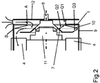
Figur 2 ist ein Ausschnitt ausFigur 1 um den Lüfter 5 herum gezeigt. - In der
Figur 3 ist eine Ansicht in axialer Richtung gezeigt. - In der
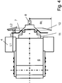
Figur 4 ist beim Querschnitt nachFigur 1 die Lüfterhaube entfernt. - In der
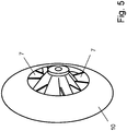
Figur 5 ist eine Schrägansicht aus einer ersten Blickrichtung auf den Lüfter 5 gezeigt. - In der
Figur 6 ist eine Schrägansicht aus einer anderen Blickrichtung auf den Lüfter 5 gezeigt. - In der
Figur 7 läuft im Unterschied zurFigur 2 das Trennblech 1 auf das Deckblech radial und axial ungefähr mittig zu. - Wie in den Figuren dargestellt, ist ein Lüfter 5 auf der eintreibenden Welle 8 des Getriebes 6 drehfest verbunden. An dem Getriebegehäuse ist eine Lüfterhaube 9 angeordnet, die den Lüfter 5 umgibt.
- Das Getriebe ist als Kegelradgetriebe ausgeführt, weshalb die eintreibende Welle 8 in einem Kegeltopfgehäuseteil 11 gelagert ist, das mit dem Gehäuse des Getriebes 6 verbunden ist.
- Der Lüfter 5 umfasst ein Radiallüfterrad, dessen Lüfterflügel 7 sich radial, insbesondere nur radial erstrecken. Somit ist eine drehrichtungsunabhängige Luftförderung ermöglicht.
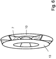
- Wie in
Figur 6 dargestellt, weist das Radiallüfterrad eine erste Deckscheibe 10 und eine zweite Deckscheibe 13 auf, zwischen denen die Lüfterflügel 7 angeordnet sind. Die erste Deckscheibe 10 und die zweite Deckscheibe 13 sind also axial voneinander beabstandet. Die Lüfterflügel 7 überdecken den axialen Zwischenbereich zwischen der ersten und zweiten Deckscheibe 10, 13. - Die Lüfterhaube 9 weist ein Trennblech 1 auf, das sich radial erstreckt und an einer axialen Position angeordnet ist, die auf der vom Getriebe mit Kegeltopfgehäuseteil 11 axial abgewandten Seite angeordnet ist. Das Trennblech 1 weist eine mittig angeordnete Öffnung auf, so dass die Luft aus axialer Richtung eingelassen wird. Allerdings ist die Öffnung im Trennblech 1 derart klein ausgeführt, dass die eingelassene Luft nicht auf den äußeren Rand des Lüfterrads trifft. Hierzu ist der Innendurchmesser der Öffnung der Trennscheibe 1 kleiner als der maximale Außendurchmesser des Lüfters 5.
- Durch die Anordnung des Lüfters 5 auf der eintreibenden Welle des als Untersetzungsgetriebe ausgeführten Getriebes ist der Lüfter 5 auf der am schnellsten drehenden Welle, nämlich auf der eintreibenden Welle 8, angeordnet.
- Die Lüfterhaube 9 lenkt den vom Lüfter 5 geförderten Luftstrom aus der radialen in die axiale Richtung um. Mittels Verengungen erzeugenden Mitteln ist im axialen Austrittsbereich eine Düse 3 und somit eine erhöhte Austrittsgeschwindigkeit erreicht.
- Die Austrittsöffnungen der Lüfterhaube 9 sind an ihrer vom Eintrieb abgewandten Seite derart angeordnet, dass der austretende Luftstrom entlang des Getriebegehäuses strömt.
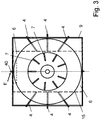
- Allerdings ist das Getriebe, wie in der Draufsicht aus
Figur 3 ersichtlich, im Wesentlichen quaderförmig ausgeführt, so dass die Frontseite eine im Wesentlichen rechteckförmige Kontur aufweist. Die Lüfterhaube 9 hat ebenfalls eine rechteckige Form, die vorzugsweise im Wesentlichen quadratisch ist und insbesondere eine größere Querschnittsfläche aufweist als der Lüfter 5 und das Getriebegehäuse, insbesondere in Draufsicht gemäßFigur 3 . - Dabei ist in
Figur 3 das Getriebegehäuse gestrichelt angedeutet. - Der maximale Außendurchmesser des Lüfters 5 ist größer als die Breite des Getriebegehäuses aber kleiner als die Höhe des Getriebegehäuses. Ebenso ist die Lüfterhaube breiter als die Breite des Getriebegehäuses. Die Austrittsöffnung zwischen Lüfter 5 und Getriebegehäuse ist daher groß, insbesondere entspricht sie ungefähr der Differenz zwischen der Breite der Lüfterhaube 9 und der Breite des Getriebegehäuses.
- Zur Verhinderung von Drall bei dem vom Lüfter 5 geförderten Luftstrom weist die Lüfterhaube 9 radial ausgerichtete und sich erstreckende Luftleitbleche 4 auf. Somit wird also der Drehimpuls des geförderten Luftstroms reduziert. Dabei erstreckt sich jedes der Luftleitbleche von der Lüfterhaube bis zum Getriebegehäuse. Je nach i Umfangswinkelposition des jeweiligen Luftleitblechs 4 ist die radiale Ausdehnung verschieden. Die Luftleitbleche 4 wirken also als Antidrallbleche für den austretenden Luftstrom.
- Der Durchmesser des Lüfters 5 ist kleiner als die Höhe des Getriebegehäuses.
- Das erste Deckblech 10 ist konisch geformt, wobei die Konusspitze entfernt ist. Die so vorhandene Öffnung ist als Lufteintritt wirksam und weist einen Durchmesser auf, der kleiner oder gleich ist wie der Durchmesser der durch das Trennblech 1 bereit gestellten Lufteinlass-Öffnung.
- Nach Lufteintritt in den in Umfangsrichtung durch die Lüfterflügel 7 begrenzten Förderkanal des Lüfters 5 wächst der Kanalquerschnitt Q2 vom Einströmquerschnitt Q1 an bis er den Ausströmquerschnitt Q3 erreicht. Vorzugsweise ist dabei das Anwachsen, also die Zunahme, des Querschnitts Q2 monoton. Der Lüfter arbeitet also einerseits als Diffusor, andererseits ist aber durch die Ausbildung als Radiallüfter eine Förderwirkung in radialer Richtung vorhanden. Somit wird ein relativ hoher Druck bei relativ kleiner Strömungsgeschwindigkeit vom Radiallüfter erzeugt.
- Die zweite Deckscheibe 13 ist vorzugsweise eben ausgeführt, erstreckt sich also in radialer Richtung und in Umfangsrichtung.
- Wie in
Figur 1 gezeigt, erfolgt der Luftzutritt in den von der Lüfterhaube 9 umgebenen Bereich aus radialer Richtung, weil die zugehörige Öffnung in radialer Richtung in die Umgebung mündet. - Mittels des Deckblechs 12 wird die eingetretene Luft nach radial weiter innen geführt und strömt dort im Öffnungsbereich des Trennblechs 1 axial in den Lüfter 5 ein. Der vom Lüfter 5 radial herausgeförderte Luftstrom wird von der Lüfterhaube 9 umgelenkt. Der Austritt des Luftstroms erfolgt in axialer Richtung entlang des Getriebegehäuses. Im Austrittsbereich der Lüfterhaube 9 bewirkt die Verengung einen Düseneffekt und somit eine Erhöhung der Strömungsgeschwindigkeit des austretenden Luftstroms.
- Durch das Deckblech 12 ist der radial gerichtete Lufteintritt ermöglicht. Somit ist die eintreibende Welle 8 mit einer antreibenden Welle eines das Getriebe antreibenden Elektromotors verbindbar.
- Der von der Lüfterhaube 9 überdeckte axiale Bereich umfasst den von den Lüfterflügeln 7 überdeckten axialen Bereich und zumindest teilweise auch den von den Luftleitblechen 4 überdeckten axialen Bereich.
- Lüfterhaube 12 und Trennblech 1 sind einstückig fertigbar, insbesondere aus einem Metallblech, insbesondere Stahlblech. Eine besonders einfache und kostengünstige Herstellung ist erreichbar durch die Fertigung als Stanz-Biegeteil. Auch eine zweistückige Ausführung ist vorteilhaft, insbesondere bei kleinen Stückzahlen.
- Wie in
Figur 3 gezeigt, weist die Lüfterhaube einen rechteckförmigen Querschnitt auf. Dabei ist die Normale der Querschnittsfläche parallel zur Achse der eintreibenden Welle ausgerichtet. - Zur Reduzierung von Wirbelverlusten sind die Luftleitbleche 4 axial beabstandet von dem Lüfter 5.
- Die Lüfterflügel 7 sind in Umfangsrichtung nicht gleichmäßig voneinander beabstandet, so dass Verluste, insbesondere Körperschall- und Luftschallverluste, reduzierbar sind. Vorzugsweise sind neun Lüfterflügel 7 vorhanden.
- Die Nabe des Lüfterrades ist konisch ausgeführt, wobei der Umfang der Nabe in Strömungsrichtung zur Umleitung der Luft in radiale Richtung zunimmt.
- Wie in
Figur 3 gezeigt, sind in Umfangsrichtung sechs radial lang sich erstreckende Luftleitbleche 4 vorhanden und zwei weitere, radial sich kurz erstreckende Luftleitbleche 40, die im oberen und im unteren Bereich der Lüfterhaube 9 angeordnet sind. - Die Druckseite und die Saugseite sind somit getrennt durch das Trennblech 1. Dabei ist die im Trennblech 1 angeordnete Öffnung für den Lufteintritt kreisförmig ausgeschnitten, wobei der Mittelpunkt des Kreises auf der gedachten Achse der eintreibenden Welle liegt.
- Die Düse 3 ist durch Anstellung der Hinterkante der Lüfterhaube 9 einfach herstellbar. Die Anstellung weist einen Winkel zwischen 10° und 40° auf.
- Das Deckblech 12 leitet die Luft von radial außen nach radial weiter innen. Somit ist an dem vom Lüfter 5 abgewandten axialen Endbereich der eintreibenden Welle ein beliebiger Anbau vorsehbar. Denn diese axial sich vom Deckblech und dem Getriebe weiter weg erstreckenden Anbauten haben keinen wesentlichen Einfluss auf die Luftströmung. Denn das Deckblech 12 ermöglicht den Zustrom der kühlen Umgebungsluft aus radialer Richtung. Selbst wenn also die Anbauten eine heiße Oberfläche aufweisen, transportiert kein Luftstrom Wärme von den Anbauten in den Lüfter. Insbesondere ist also eine Kupplung zwischen dem antreibenden Elektromotor und dem Getriebe, insbesondere der eintreibenden Welle des Getriebes, anordenbar. Gerade bei einer an der eintreibenden Welle 8 angeordneten Fluidkupplung, also hydraulisch arbeitenden Kupplung, welche eine große Ausdehnung in radialer Richtung aufweist, wird trotzdem durch das Deckblech 12 der Zutritt kühler Luft zum Lüfter 5 bewirkbar.
- Das Deckblech 12 ist über ein Eingreifschutzgehäuseteil 14 mit der Lüfterhaube 9 verbunden. Das Eingreifschutzgehäuseteil 14 weist Ausnehmungen auf, die derart klein sind, dass kein menschlicher Finger eines Erwachsenen hindurchpasst, aber groß genug sind, um den Luftstrom mit möglichst geringem Widerstand einzulassen
- Außerdem ermöglicht das Deckblech 12 ein Anströmen der Luft aus allen Umfangswinkelpositionen. Dabei ist eine gleichmäßige Verteilung erreicht.
- Der Ausströmquerschnitt Q3 ist vorzugsweise zwischen 1,1 mal und 1,3 mal größer als der Einströmquerschnitt Q1. Die in
Figur 4 gezeigte Schaufelkanallänge L2 beträgt zwischen dem 0,3 fachen und 0,5 fachen des Lüfterradius RL. Der jeweilige Schaufelkanal ist zumindest in Umfangsrichtung durch die beiden jeweils nächstbenachbarten Lüfterflügel 7 begrenzt und in axialer Richtung einerseits durch die erste Deckscheibe 10 und andererseits durch die zweite Deckscheibe 13. - Vorzugsweise grenzt das Trennblech ans Lüfterrad an, wobei eine Beabstandung, also ein Spalt, vorgesehen ist, wobei die Spaltbreite des Spalts, insbesondere also der vom Spalt überdeckte Radialabstandsbereich, kleiner als 10%, insbesondere kleiner als 5%, insbesondere kleiner als 5% und größer als 0,1%, des Außendurchmessers des Lüfterrads ist.
- Wie bei dem weiteren Ausführungsbeispiel nach
Figur 7 gezeigt, ist der Lüfter 5 anders ausgeführt als beiFigur 2 . Denn die erste Deckscheibe 10 ist weiter nach radial innen erstreckt und der Lüfter 5 dann weiter axial durch die Ausnehmung des Trennblechs 1 hindurchragend. Somit überdeckt der vom Lüfter 5 überdeckte axiale Beriech auch den axialen Bereich des Trennblechs 1. - Insbesondere ist der kleinste Radialabstand des Trennblechs 1 innerhalb des vom Lüfter 5, insbesondere von dessen erster Deckscheibe 10, überdeckten Radialabstandsberiech angeordnet.
- Darüber hinaus ist die axiale Position des Trennblechs 1 oder der vom Trennblech 1 überdeckte axiale Bereich innerhalb des vom Lüfter 5, insbesondere von dessen erster Deckscheibe 10, überdeckten axialen Bereichs angeordnet.
- Vorzugsweise ist dabei die Kante des Trennblechs 1, welche die durch das Trennblech 1 bereit gestellte Lufteinlass-Öffnung umrandet, mittig in dem von der ersten Deckscheibe 10 überdeckten axialen Beriech und mittig in dem von der ersten Deckscheibe 10 überdeckten Radialabstandsbereich angeordnet.
- Bei weiteren erfindungsgemäßen Ausführungsbeispielen weist das Deckblech 12 Ausnehmungen auf, so dass zusätzlich auch ein axialer Lufteintritt ermöglicht ist.
- Bei weiteren erfindungsgemäßen Ausführungsbeispielen liegt das Trennblech 1 im Unterschied zur
Figur 2 nicht am Innenradius des Lüfters 5 an sondern am Außenradius, wobei in beiden Fällen eine kleine Beabstandung in radialer Richtung zwischen dem Trennblech 1 und dem Lüfter 5 zur Vermeidung von Berührung besteht. Die Beabstandung ist aber unter Berücksichtigung der Fertigungstoleranzen möglichst klein gewählt, so dass die Verluste durch Verwirbelung der Strömung, insbesondere rückwirkende Wirbelströme, gering bleiben. - Bei weiteren erfindungsgemäßen Ausführungsbeispielen ist das Trennblech 1 nicht einstückig mit der restlichen Lüfterhaube ausgeführt, so dass ein einfaches Auswechseln ermöglicht ist.
-
- 1 Trennblech
- 2 Luftzuführbereich
- 3 Düse
- 4 Luftleitblech
- 5 Lüfter
- 6 Getriebe
- 7 Lüfterflügel
- 8 Eintriebswelle
- 9 Lüfterhaube
- 10 erste Deckscheibe
- 11 Kegeltopfgehäuse
- 12 Deckblech
- 13 zweite Deckscheibe
- 14 Eingreifschutzgehäuseteil
- 15 Getriebegehäusekante
- 40 Luftleitblech
- A Öffnungsquerschnitt
- Q1 Einströmquerschnitt
- Q2 Kanalquerschnitt
- Q3 Ausströmquerschnitt
Claims (18)
- Getriebe (6) mit einer Welle, insbesondere eintreibende Welle,
wobei ein Lüfterrad drehfest mit der Welle verbunden ist,
wobei mit dem Getriebegehäuse eine Lüfterhaube (9) verbunden ist, die das Lüfterrad zumindest teilweise umgibt,
wobei mit der Lüfterhaube (9) ein Trennblech (1) zur Trennung des Druckraums des Lüfters vom Saugraum des Lüfters verbunden ist,
wobei das Trennblech (1) eine Lufteintrittsöffnung für das Lüfterrad aufweist und auf der vom Getriebe (6) axial abgewandten Seite des Lüfterrades angeordnet ist,
wobei das Lüfterrad eine erste und eine zweite Deckscheibe (10, 13) aufweist, die axial voneinander beabstandet sind und Lüfterflügel (7) zwischen den Deckscheiben (10, 13) angeordnet sind, so dass Kanäle gebildet sind, wobei der Radialabstand der Lufteintrittsöffnung innerhalb, insbesondere mittig innerhalb, des von der ersten Deckscheibe (10) überdeckten Radialabstandsbereich angeordnet ist und
wobei die Lufteintrifttsöffnung axial innerhalb, insbesondere mittig innerhalb, des von der erster Deckscheibe (10) überdeckten axialen Bereichs angeordnet ist,
wobei das Trennblech (1) ans Lüfterrad angrenzt, wobei eine Beabstandung vorgesehen ist, die eine Berührung von Trennblech (1) und Lüfterrad verhindert, dadurch gekennzeichnet, dass zumindest eine der Deckscheiben (10, 13) konisch geformt ist und das Lüfterrad ein Radiallüfterrad mit Diffusoreffekt. - Getriebe (6) nach Anspruch 1,
dadurch gekennzeichnet, dass
die Lüfterflügel (7) des Lüfterrads in Umfangsrichtung unregelmäßig voneinander beabstandet sind. - Getriebe (6) nach mindestens einem der vorangegangenen Ansprüche,
dadurch gekennzeichnet, dass
das Trennblech (1) ans Lüfterrad angrenzt, wobei eine Beabstandung, also ein Spalt, vorgesehen ist, wobei die Spaltbreite des Spalts, insbesondere also der vom Spalt überdeckte Radialabstandsbereich, kleiner als 10%, insbesondere kleiner als 5%, insbesondere kleiner als 5% und größer als 0,1%, des Außendurchmessers des Lüfterrads ist. - Getriebe (6) nach mindestens einem der vorangegangenen Ansprüche,
dadurch gekennzeichnet, dass
die Lüfterhaube (9) und/oder das Getriebegehäuse rechteckförmig ist - Getriebe (6) nach mindestens einem der vorangegangenen Ansprüche,
dadurch gekennzeichnet, dass
der Außendurchmesser des Lüfterrads größer ist als die Breite des Getriebegehäuses oder kleiner ist als die Höhe des Getriebegehäuses. - Getriebe (6) nach mindestens einem der vorangegangenen Ansprüche,
dadurch gekennzeichnet, dass
Luftleitblech (4, 40) zur Verhinderung oder Verminderung von Drall des aus der Lüfterhaube (9) ausströmenden Luftstroms zwischen Lüfterhaube (9) und Getriebegehäuse angeordnet sind,
wobei die Luftleitbleche (4, 40) axial beabstandet sind vom Lüfterrad. - Getriebe (6) nach mindestens einem der vorangegangenen Ansprüche,
dadurch gekennzeichnet, dass
die Lüfterhaube (9) im Luftaustrittsbereich als Düse (3) ausgeformt ist, so dass ein austretender Luftstrom entlang dem Getriebegehäuse strömt. - Getriebe (6) nach mindestens einem der vorangegangenen Ansprüche,
dadurch gekennzeichnet, dass
ein Deckblech (12) axial vom Trennblech (1) beabstandet ist, so dass der Luftzutritt aus radialer Richtung erfolgt. - Getriebe (6) nach Anspruch 9,
dadurch gekennzeichnet, dass
das Deckblech (12) Ausnehmungen aufweist zur Ermöglichung von zusätzlich axial eintretendem Luftstrom. - Getriebe (6) nach Anspruch 9 oder 10,
dadurch gekennzeichnet, dass
zwischen Deckblech (12) und Trennblech (1) ein Eingreifschutzgehäuseteil angeordnet ist, über welches das Deckblech (12) am Trennblech (1) gehalten ist. - Getriebe (6) nach mindestens einem der vorangegangenen Ansprüche,
dadurch gekennzeichnet, dass
das Trennblech (1) lösbar verbunden ist mit der Lüfterhaube (9), insbesondere so dass durch Austausch des Trennblechs wahlweise unterschiedlich große Lüfterräder in der Lüfterhaube (9) vorsehbar sind. - Getriebe (6) nach mindestens einem der vorangegangenen Ansprüche,
dadurch gekennzeichnet, dass
ein Deckblech (12) axial vom Trennblech (1) beabstandet ist. - Getriebe (6) nach mindestens einem der vorangegangenen Ansprüche,
dadurch gekennzeichnet, dass
die Lüfterhaube (9), insbesondere mit Trennblech (1), als Stanz-Biegeteil ausgeführt ist. - Getriebe (6) nach Anspruch 7,
dadurch gekennzeichnet, dass
die Düse (3) durch Anstellung einer Lüfterhaubenkante im Luftaustrittsbereich ausgeführt ist, insbesondere wobei der Anstellwinkel zwischen 10° und 40° ist. - Getriebe (6) nach mindestens einem der vorangegangenen Ansprüche,
dadurch gekennzeichnet, dass
der Außenradius des Lüfterrads größer ist als die Breite des Getriebes (6) und kleiner ist als die Höhe des Getriebes (6). - Getriebe (6) nach einem der Ansprüche 1 bis 12,
dadurch gekennzeichnet, dass
der Außenradius des Lüfterrads kleiner als die Breite des Getriebes (6) und kleiner als die Höhe des Getriebes (6), wobei der Radius der Öffnung des Trennblechs dem Außenradius des durch die Kanäle des Lüfterrades gebildeten Lufteintrittsbereichs des Lüfterrades, insbesondere im Wesentlichen, gleicht. - Getriebe (6) nach mindestens einem der vorangegangenen Ansprüche,
dadurch gekennzeichnet, dass
die Luftleitblech (4, 40) sich radial erstrecken vom Getriebegehäuse zur Lüfterhaube (9). - Getriebe (6) nach mindestens einem der vorangegangenen Ansprüche,
dadurch gekennzeichnet, dass
das Lüfterrad eine erste und eine zweite Deckscheibe (10, 13) aufweist, die axial voneinander beabstandet sind und Lüfterflügel (7) zwischen den Deckscheiben (10, 13) angeordnet sind, so dass Kanäle gebildet sind,
wobei der Kanalquerschnitt (Q2) vom radial weiter innen liegenden Eintrittsbereich am Lüfterrad zum radial weiter außen liegenden Austrittsbereich am Lüfterrad monoton zunimmt,
insbesondere wobei der Eintrittsbereich an einer axialen Position erfolgt, insbesondere also die Eintrittsbereichsfläche eine sich nur radial und in Umfangsrichtung erstreckende Fläche und die Austrittsbereichsfläche eine sich in radialer Richtung, in Umfangsrichtung und in axialer Richtung erstreckende Fläche ist.
Applications Claiming Priority (2)
| Application Number | Priority Date | Filing Date | Title |
|---|---|---|---|
| DE102013005430.3A DE102013005430A1 (de) | 2013-03-28 | 2013-03-28 | Getriebe mit einer Welle |
| PCT/EP2014/000382 WO2014154316A1 (de) | 2013-03-28 | 2014-02-12 | Getriebe mit einer welle |
Publications (2)
| Publication Number | Publication Date |
|---|---|
| EP2978976A1 EP2978976A1 (de) | 2016-02-03 |
| EP2978976B1 true EP2978976B1 (de) | 2018-10-10 |
Family
ID=50150683
Family Applications (1)
| Application Number | Title | Priority Date | Filing Date |
|---|---|---|---|
| EP14705476.1A Active EP2978976B1 (de) | 2013-03-28 | 2014-02-12 | Getriebe mit einer welle |
Country Status (8)
| Country | Link |
|---|---|
| US (1) | US10718353B2 (de) |
| EP (1) | EP2978976B1 (de) |
| CN (1) | CN104903592B (de) |
| AU (1) | AU2014243451B2 (de) |
| BR (1) | BR112015015228B1 (de) |
| DE (1) | DE102013005430A1 (de) |
| WO (1) | WO2014154316A1 (de) |
| ZA (1) | ZA201505210B (de) |
Families Citing this family (9)
| Publication number | Priority date | Publication date | Assignee | Title |
|---|---|---|---|---|
| JP6403623B2 (ja) * | 2015-03-31 | 2018-10-10 | 住友重機械工業株式会社 | 減速装置 |
| CN106382360A (zh) * | 2016-11-16 | 2017-02-08 | 常州耐强传动机械有限公司 | 减速机降压系统 |
| JP6771663B2 (ja) * | 2017-05-01 | 2020-10-21 | 三菱電機株式会社 | 電動送風機、電気掃除機、およびハンドドライヤー |
| WO2020164795A1 (de) | 2019-02-12 | 2020-08-20 | Sew-Eurodrive Gmbh & Co. Kg | Antriebssystem, aufweisend einen elektromotor, ein getriebe und einen einen lüfter aufweisenden adapter |
| US11536362B2 (en) | 2019-03-26 | 2022-12-27 | Sew-Eurodrive Gmbh & Co. Kg | Transmission having a fan assembly |
| CN114175468A (zh) * | 2019-07-19 | 2022-03-11 | 索尤若驱动有限及两合公司 | 具有通过联轴器由电机驱动的减速器的减速电机 |
| JP7348500B2 (ja) * | 2019-09-30 | 2023-09-21 | ダイキン工業株式会社 | ターボファン |
| CN112128116B (zh) * | 2020-09-23 | 2022-01-14 | 泗县金皖泵业有限公司 | 一种齿轮变速盘式水泵 |
| DE102021205526A1 (de) * | 2021-05-31 | 2022-12-01 | Dana Motion Systems Deutschland GmbH | Luftkühlanordnung |
Family Cites Families (12)
| Publication number | Priority date | Publication date | Assignee | Title |
|---|---|---|---|---|
| US3692428A (en) * | 1970-01-12 | 1972-09-19 | Gen Ind Co The | Centrifugal blower |
| GB2282206B (en) | 1993-09-23 | 1997-10-08 | Brown Gear Ind | Gearbox |
| JP3406402B2 (ja) | 1994-10-04 | 2003-05-12 | 株式会社日立製作所 | 空冷歯車変速機 |
| DE69518819T2 (de) | 1994-11-23 | 2001-01-18 | Ametek Inc | Rotierende Lüfter mit konischem Scheibenteil |
| JPH1061754A (ja) | 1996-08-13 | 1998-03-06 | Hitachi Ltd | 空冷歯車変速機 |
| DE102005031197B4 (de) | 2005-07-01 | 2016-10-13 | Sew-Eurodrive Gmbh & Co Kg | Antrieb und Lüfter |
| DE102007008658A1 (de) | 2007-02-20 | 2008-08-21 | Flender Industriegetriebe Gmbh & Co. Kg | Kegelradgetriebe, insbesondere Kegelstirnradgetriebe |
| DE102007009366B4 (de) | 2007-02-23 | 2017-06-14 | Sew-Eurodrive Gmbh & Co Kg | Lüfterrad, System und Getriebebaureihe |
| JP4891172B2 (ja) | 2007-07-26 | 2012-03-07 | 本田技研工業株式会社 | ベルト式無段変速機の冷却構造。 |
| DE102009014316B4 (de) | 2009-03-25 | 2019-03-14 | Sew-Eurodrive Gmbh & Co Kg | Getriebe |
| CN202031881U (zh) | 2011-03-15 | 2011-11-09 | 苏州工业园区星德胜电机有限公司 | 一种吸尘器电机风机结构 |
| DE102012013351A1 (de) | 2012-07-06 | 2014-05-08 | Sew-Eurodrive Gmbh & Co Kg | Getriebe mit einer Welle |
-
2013
- 2013-03-28 DE DE102013005430.3A patent/DE102013005430A1/de active Pending
-
2014
- 2014-02-12 CN CN201480004180.9A patent/CN104903592B/zh active Active
- 2014-02-12 US US14/780,790 patent/US10718353B2/en active Active
- 2014-02-12 EP EP14705476.1A patent/EP2978976B1/de active Active
- 2014-02-12 WO PCT/EP2014/000382 patent/WO2014154316A1/de active Application Filing
- 2014-02-12 AU AU2014243451A patent/AU2014243451B2/en active Active
- 2014-02-12 BR BR112015015228-7A patent/BR112015015228B1/pt active IP Right Grant
-
2015
- 2015-07-20 ZA ZA2015/05210A patent/ZA201505210B/en unknown
Non-Patent Citations (1)
| Title |
|---|
| None * |
Also Published As
| Publication number | Publication date |
|---|---|
| CN104903592A (zh) | 2015-09-09 |
| AU2014243451A1 (en) | 2015-07-23 |
| US20160053775A1 (en) | 2016-02-25 |
| US10718353B2 (en) | 2020-07-21 |
| ZA201505210B (en) | 2016-11-30 |
| BR112015015228A2 (pt) | 2017-07-11 |
| EP2978976A1 (de) | 2016-02-03 |
| BR112015015228B1 (pt) | 2022-03-03 |
| AU2014243451B2 (en) | 2017-10-05 |
| CN104903592B (zh) | 2017-12-26 |
| DE102013005430A1 (de) | 2014-10-02 |
| WO2014154316A1 (de) | 2014-10-02 |
Similar Documents
| Publication | Publication Date | Title |
|---|---|---|
| EP2978976B1 (de) | Getriebe mit einer welle | |
| EP2870382B1 (de) | Getriebe mit einer welle und darauf angebrachtem lüfter in einer lüfterhaube | |
| EP2778432B1 (de) | Ventilatoranordnung mit Strömungsgleichrichter | |
| DE102008056459A1 (de) | Diagonallüfter | |
| EP2716915B1 (de) | Gehäuse für einen Axialventilator | |
| DE102012025596A1 (de) | Getriebe mit einer Welle | |
| EP3334942B1 (de) | Dunstabzugsvorrichtung mit diagonalventilator | |
| EP2350533B1 (de) | Gargerät mit einer strömungsleitvorrichtung | |
| DE102010046672A1 (de) | Fahrzeuglüfter und Belüftungsanlage | |
| DE102008053144A1 (de) | Lüfteranordnung und Gargerät | |
| DE10162919A1 (de) | Lüftervorrichtung | |
| EP2329149B1 (de) | Diagonallüfter | |
| EP2940311A1 (de) | Radialgebläse mit verbesserter anströmkantengeometrie | |
| EP3524823A1 (de) | Radialventilator mit motorkühlung | |
| EP1122444B1 (de) | Radialventilator und Düse für einen Radialventilator | |
| EP3161351B1 (de) | Antrieb | |
| DE102012025597A1 (de) | Getriebe mit einer Welle | |
| DE102015009540A1 (de) | Elektromotor mit Lüfter, Lüfterhaube, Motorgehäuse, aufweisend Gehäuseteil, Flanschteil und Statorgehäuse | |
| DE102020000478A1 (de) | Antriebssystem, aufweisend einen Elektromotor, ein Gehäuse und einen einen Lüfter aufweisenden Adapter | |
| EP2940310B1 (de) | Radialgebläse mit verbesserter überströmkantengeometrie | |
| EP2465647A2 (de) | Handwerkzeugmaschine mit Luftführungselement | |
| DE102014009311A1 (de) | Antrieb | |
| EP2180196A1 (de) | Lüfteranordnung | |
| DE3905092C2 (de) | ||
| DE102014009312A1 (de) | Antrieb |
Legal Events
| Date | Code | Title | Description |
|---|---|---|---|
| PUAI | Public reference made under article 153(3) epc to a published international application that has entered the european phase |
Free format text: ORIGINAL CODE: 0009012 |
|
| 17P | Request for examination filed |
Effective date: 20151028 |
|
| AK | Designated contracting states |
Kind code of ref document: A1 Designated state(s): AL AT BE BG CH CY CZ DE DK EE ES FI FR GB GR HR HU IE IS IT LI LT LU LV MC MK MT NL NO PL PT RO RS SE SI SK SM TR |
|
| AX | Request for extension of the european patent |
Extension state: BA ME |
|
| DAX | Request for extension of the european patent (deleted) | ||
| STAA | Information on the status of an ep patent application or granted ep patent |
Free format text: STATUS: EXAMINATION IS IN PROGRESS |
|
| 17Q | First examination report despatched |
Effective date: 20170306 |
|
| GRAP | Despatch of communication of intention to grant a patent |
Free format text: ORIGINAL CODE: EPIDOSNIGR1 |
|
| STAA | Information on the status of an ep patent application or granted ep patent |
Free format text: STATUS: GRANT OF PATENT IS INTENDED |
|
| INTG | Intention to grant announced |
Effective date: 20180523 |
|
| GRAS | Grant fee paid |
Free format text: ORIGINAL CODE: EPIDOSNIGR3 |
|
| GRAA | (expected) grant |
Free format text: ORIGINAL CODE: 0009210 |
|
| STAA | Information on the status of an ep patent application or granted ep patent |
Free format text: STATUS: THE PATENT HAS BEEN GRANTED |
|
| AK | Designated contracting states |
Kind code of ref document: B1 Designated state(s): AL AT BE BG CH CY CZ DE DK EE ES FI FR GB GR HR HU IE IS IT LI LT LU LV MC MK MT NL NO PL PT RO RS SE SI SK SM TR |
|
| REG | Reference to a national code |
Ref country code: GB Ref legal event code: FG4D Free format text: NOT ENGLISH |
|
| REG | Reference to a national code |
Ref country code: CH Ref legal event code: EP Ref country code: CH Ref legal event code: NV Representative=s name: HEPP WENGER RYFFEL AG, CH Ref country code: AT Ref legal event code: REF Ref document number: 1051570 Country of ref document: AT Kind code of ref document: T Effective date: 20181015 |
|
| REG | Reference to a national code |
Ref country code: IE Ref legal event code: FG4D Free format text: LANGUAGE OF EP DOCUMENT: GERMAN |
|
| REG | Reference to a national code |
Ref country code: DE Ref legal event code: R096 Ref document number: 502014009703 Country of ref document: DE |
|
| REG | Reference to a national code |
Ref country code: NL Ref legal event code: FP |
|
| REG | Reference to a national code |
Ref country code: LT Ref legal event code: MG4D |
|
| PG25 | Lapsed in a contracting state [announced via postgrant information from national office to epo] |
Ref country code: LV Free format text: LAPSE BECAUSE OF FAILURE TO SUBMIT A TRANSLATION OF THE DESCRIPTION OR TO PAY THE FEE WITHIN THE PRESCRIBED TIME-LIMIT Effective date: 20181010 Ref country code: LT Free format text: LAPSE BECAUSE OF FAILURE TO SUBMIT A TRANSLATION OF THE DESCRIPTION OR TO PAY THE FEE WITHIN THE PRESCRIBED TIME-LIMIT Effective date: 20181010 Ref country code: ES Free format text: LAPSE BECAUSE OF FAILURE TO SUBMIT A TRANSLATION OF THE DESCRIPTION OR TO PAY THE FEE WITHIN THE PRESCRIBED TIME-LIMIT Effective date: 20181010 Ref country code: IS Free format text: LAPSE BECAUSE OF FAILURE TO SUBMIT A TRANSLATION OF THE DESCRIPTION OR TO PAY THE FEE WITHIN THE PRESCRIBED TIME-LIMIT Effective date: 20190210 Ref country code: NO Free format text: LAPSE BECAUSE OF FAILURE TO SUBMIT A TRANSLATION OF THE DESCRIPTION OR TO PAY THE FEE WITHIN THE PRESCRIBED TIME-LIMIT Effective date: 20190110 Ref country code: BG Free format text: LAPSE BECAUSE OF FAILURE TO SUBMIT A TRANSLATION OF THE DESCRIPTION OR TO PAY THE FEE WITHIN THE PRESCRIBED TIME-LIMIT Effective date: 20190110 Ref country code: PL Free format text: LAPSE BECAUSE OF FAILURE TO SUBMIT A TRANSLATION OF THE DESCRIPTION OR TO PAY THE FEE WITHIN THE PRESCRIBED TIME-LIMIT Effective date: 20181010 Ref country code: HR Free format text: LAPSE BECAUSE OF FAILURE TO SUBMIT A TRANSLATION OF THE DESCRIPTION OR TO PAY THE FEE WITHIN THE PRESCRIBED TIME-LIMIT Effective date: 20181010 |
|
| PG25 | Lapsed in a contracting state [announced via postgrant information from national office to epo] |
Ref country code: RS Free format text: LAPSE BECAUSE OF FAILURE TO SUBMIT A TRANSLATION OF THE DESCRIPTION OR TO PAY THE FEE WITHIN THE PRESCRIBED TIME-LIMIT Effective date: 20181010 Ref country code: SE Free format text: LAPSE BECAUSE OF FAILURE TO SUBMIT A TRANSLATION OF THE DESCRIPTION OR TO PAY THE FEE WITHIN THE PRESCRIBED TIME-LIMIT Effective date: 20181010 Ref country code: PT Free format text: LAPSE BECAUSE OF FAILURE TO SUBMIT A TRANSLATION OF THE DESCRIPTION OR TO PAY THE FEE WITHIN THE PRESCRIBED TIME-LIMIT Effective date: 20190210 Ref country code: AL Free format text: LAPSE BECAUSE OF FAILURE TO SUBMIT A TRANSLATION OF THE DESCRIPTION OR TO PAY THE FEE WITHIN THE PRESCRIBED TIME-LIMIT Effective date: 20181010 Ref country code: GR Free format text: LAPSE BECAUSE OF FAILURE TO SUBMIT A TRANSLATION OF THE DESCRIPTION OR TO PAY THE FEE WITHIN THE PRESCRIBED TIME-LIMIT Effective date: 20190111 |
|
| REG | Reference to a national code |
Ref country code: DE Ref legal event code: R097 Ref document number: 502014009703 Country of ref document: DE |
|
| PG25 | Lapsed in a contracting state [announced via postgrant information from national office to epo] |
Ref country code: DK Free format text: LAPSE BECAUSE OF FAILURE TO SUBMIT A TRANSLATION OF THE DESCRIPTION OR TO PAY THE FEE WITHIN THE PRESCRIBED TIME-LIMIT Effective date: 20181010 Ref country code: CZ Free format text: LAPSE BECAUSE OF FAILURE TO SUBMIT A TRANSLATION OF THE DESCRIPTION OR TO PAY THE FEE WITHIN THE PRESCRIBED TIME-LIMIT Effective date: 20181010 |
|
| PLBE | No opposition filed within time limit |
Free format text: ORIGINAL CODE: 0009261 |
|
| STAA | Information on the status of an ep patent application or granted ep patent |
Free format text: STATUS: NO OPPOSITION FILED WITHIN TIME LIMIT |
|
| PG25 | Lapsed in a contracting state [announced via postgrant information from national office to epo] |
Ref country code: RO Free format text: LAPSE BECAUSE OF FAILURE TO SUBMIT A TRANSLATION OF THE DESCRIPTION OR TO PAY THE FEE WITHIN THE PRESCRIBED TIME-LIMIT Effective date: 20181010 Ref country code: SM Free format text: LAPSE BECAUSE OF FAILURE TO SUBMIT A TRANSLATION OF THE DESCRIPTION OR TO PAY THE FEE WITHIN THE PRESCRIBED TIME-LIMIT Effective date: 20181010 Ref country code: EE Free format text: LAPSE BECAUSE OF FAILURE TO SUBMIT A TRANSLATION OF THE DESCRIPTION OR TO PAY THE FEE WITHIN THE PRESCRIBED TIME-LIMIT Effective date: 20181010 Ref country code: SK Free format text: LAPSE BECAUSE OF FAILURE TO SUBMIT A TRANSLATION OF THE DESCRIPTION OR TO PAY THE FEE WITHIN THE PRESCRIBED TIME-LIMIT Effective date: 20181010 |
|
| 26N | No opposition filed |
Effective date: 20190711 |
|
| PG25 | Lapsed in a contracting state [announced via postgrant information from national office to epo] |
Ref country code: MC Free format text: LAPSE BECAUSE OF FAILURE TO SUBMIT A TRANSLATION OF THE DESCRIPTION OR TO PAY THE FEE WITHIN THE PRESCRIBED TIME-LIMIT Effective date: 20181010 Ref country code: LU Free format text: LAPSE BECAUSE OF NON-PAYMENT OF DUE FEES Effective date: 20190212 Ref country code: SI Free format text: LAPSE BECAUSE OF FAILURE TO SUBMIT A TRANSLATION OF THE DESCRIPTION OR TO PAY THE FEE WITHIN THE PRESCRIBED TIME-LIMIT Effective date: 20181010 |
|
| REG | Reference to a national code |
Ref country code: IE Ref legal event code: MM4A |
|
| PG25 | Lapsed in a contracting state [announced via postgrant information from national office to epo] |
Ref country code: IE Free format text: LAPSE BECAUSE OF NON-PAYMENT OF DUE FEES Effective date: 20190212 |
|
| PG25 | Lapsed in a contracting state [announced via postgrant information from national office to epo] |
Ref country code: TR Free format text: LAPSE BECAUSE OF FAILURE TO SUBMIT A TRANSLATION OF THE DESCRIPTION OR TO PAY THE FEE WITHIN THE PRESCRIBED TIME-LIMIT Effective date: 20181010 |
|
| PG25 | Lapsed in a contracting state [announced via postgrant information from national office to epo] |
Ref country code: MT Free format text: LAPSE BECAUSE OF FAILURE TO SUBMIT A TRANSLATION OF THE DESCRIPTION OR TO PAY THE FEE WITHIN THE PRESCRIBED TIME-LIMIT Effective date: 20181010 |
|
| PG25 | Lapsed in a contracting state [announced via postgrant information from national office to epo] |
Ref country code: CY Free format text: LAPSE BECAUSE OF FAILURE TO SUBMIT A TRANSLATION OF THE DESCRIPTION OR TO PAY THE FEE WITHIN THE PRESCRIBED TIME-LIMIT Effective date: 20181010 |
|
| PG25 | Lapsed in a contracting state [announced via postgrant information from national office to epo] |
Ref country code: HU Free format text: LAPSE BECAUSE OF FAILURE TO SUBMIT A TRANSLATION OF THE DESCRIPTION OR TO PAY THE FEE WITHIN THE PRESCRIBED TIME-LIMIT; INVALID AB INITIO Effective date: 20140212 |
|
| PG25 | Lapsed in a contracting state [announced via postgrant information from national office to epo] |
Ref country code: MK Free format text: LAPSE BECAUSE OF FAILURE TO SUBMIT A TRANSLATION OF THE DESCRIPTION OR TO PAY THE FEE WITHIN THE PRESCRIBED TIME-LIMIT Effective date: 20181010 |
|
| PGFP | Annual fee paid to national office [announced via postgrant information from national office to epo] |
Ref country code: GB Payment date: 20221230 Year of fee payment: 10 |
|
| PGFP | Annual fee paid to national office [announced via postgrant information from national office to epo] |
Ref country code: FR Payment date: 20230110 Year of fee payment: 10 Ref country code: FI Payment date: 20230220 Year of fee payment: 10 Ref country code: AT Payment date: 20230210 Year of fee payment: 10 |
|
| PGFP | Annual fee paid to national office [announced via postgrant information from national office to epo] |
Ref country code: IT Payment date: 20230110 Year of fee payment: 10 Ref country code: DE Payment date: 20230228 Year of fee payment: 10 Ref country code: BE Payment date: 20230224 Year of fee payment: 10 |
|
| PGFP | Annual fee paid to national office [announced via postgrant information from national office to epo] |
Ref country code: NL Payment date: 20230113 Year of fee payment: 10 |
|
| PGFP | Annual fee paid to national office [announced via postgrant information from national office to epo] |
Ref country code: CH Payment date: 20230427 Year of fee payment: 10 |
|
| PGFP | Annual fee paid to national office [announced via postgrant information from national office to epo] |
Ref country code: NL Payment date: 20240108 Year of fee payment: 11 |