EP2348209B1 - Ammoniakmotorensystem - Google Patents
Ammoniakmotorensystem Download PDFInfo
- Publication number
- EP2348209B1 EP2348209B1 EP09827588.6A EP09827588A EP2348209B1 EP 2348209 B1 EP2348209 B1 EP 2348209B1 EP 09827588 A EP09827588 A EP 09827588A EP 2348209 B1 EP2348209 B1 EP 2348209B1
- Authority
- EP
- European Patent Office
- Prior art keywords
- ammonia
- engine
- cracking
- exhaust gas
- catalyst
- Prior art date
- Legal status (The legal status is an assumption and is not a legal conclusion. Google has not performed a legal analysis and makes no representation as to the accuracy of the status listed.)
- Not-in-force
Links
- QGZKDVFQNNGYKY-UHFFFAOYSA-N Ammonia Chemical compound N QGZKDVFQNNGYKY-UHFFFAOYSA-N 0.000 claims description 531
- 229910021529 ammonia Inorganic materials 0.000 claims description 258
- 238000005336 cracking Methods 0.000 claims description 87
- 239000007789 gas Substances 0.000 claims description 60
- 239000003054 catalyst Substances 0.000 claims description 51
- 230000001590 oxidative effect Effects 0.000 claims description 50
- 239000001257 hydrogen Substances 0.000 claims description 20
- 229910052739 hydrogen Inorganic materials 0.000 claims description 20
- UFHFLCQGNIYNRP-UHFFFAOYSA-N Hydrogen Chemical compound [H][H] UFHFLCQGNIYNRP-UHFFFAOYSA-N 0.000 claims description 19
- 238000002485 combustion reaction Methods 0.000 claims description 19
- 238000007254 oxidation reaction Methods 0.000 claims description 15
- 229910000069 nitrogen hydride Inorganic materials 0.000 claims description 9
- 238000000034 method Methods 0.000 claims description 7
- 239000000446 fuel Substances 0.000 claims description 6
- XEEYBQQBJWHFJM-UHFFFAOYSA-N Iron Chemical compound [Fe] XEEYBQQBJWHFJM-UHFFFAOYSA-N 0.000 claims description 4
- PXHVJJICTQNCMI-UHFFFAOYSA-N Nickel Chemical compound [Ni] PXHVJJICTQNCMI-UHFFFAOYSA-N 0.000 claims description 4
- KJTLSVCANCCWHF-UHFFFAOYSA-N Ruthenium Chemical compound [Ru] KJTLSVCANCCWHF-UHFFFAOYSA-N 0.000 claims description 3
- 239000000463 material Substances 0.000 claims description 3
- 229910052707 ruthenium Inorganic materials 0.000 claims description 3
- QVGXLLKOCUKJST-UHFFFAOYSA-N atomic oxygen Chemical compound [O] QVGXLLKOCUKJST-UHFFFAOYSA-N 0.000 claims description 2
- 229910052742 iron Inorganic materials 0.000 claims description 2
- 229910052759 nickel Inorganic materials 0.000 claims description 2
- 239000001301 oxygen Substances 0.000 claims description 2
- 229910052760 oxygen Inorganic materials 0.000 claims description 2
- 229910052703 rhodium Inorganic materials 0.000 claims description 2
- 239000010948 rhodium Substances 0.000 claims description 2
- MHOVAHRLVXNVSD-UHFFFAOYSA-N rhodium atom Chemical compound [Rh] MHOVAHRLVXNVSD-UHFFFAOYSA-N 0.000 claims description 2
- 238000006243 chemical reaction Methods 0.000 description 12
- 230000003647 oxidation Effects 0.000 description 7
- IJGRMHOSHXDMSA-UHFFFAOYSA-N Atomic nitrogen Chemical compound N#N IJGRMHOSHXDMSA-UHFFFAOYSA-N 0.000 description 6
- 229910052757 nitrogen Inorganic materials 0.000 description 4
- BASFCYQUMIYNBI-UHFFFAOYSA-N platinum Chemical compound [Pt] BASFCYQUMIYNBI-UHFFFAOYSA-N 0.000 description 4
- OKTJSMMVPCPJKN-UHFFFAOYSA-N Carbon Chemical compound [C] OKTJSMMVPCPJKN-UHFFFAOYSA-N 0.000 description 2
- 230000000052 comparative effect Effects 0.000 description 2
- 150000001875 compounds Chemical class 0.000 description 2
- 230000000694 effects Effects 0.000 description 2
- 229910052697 platinum Inorganic materials 0.000 description 2
- 239000004215 Carbon black (E152) Substances 0.000 description 1
- 230000003213 activating effect Effects 0.000 description 1
- PNEYBMLMFCGWSK-UHFFFAOYSA-N aluminium oxide Inorganic materials [O-2].[O-2].[O-2].[Al+3].[Al+3] PNEYBMLMFCGWSK-UHFFFAOYSA-N 0.000 description 1
- 230000003197 catalytic effect Effects 0.000 description 1
- 239000011248 coating agent Substances 0.000 description 1
- 238000000576 coating method Methods 0.000 description 1
- 239000000567 combustion gas Substances 0.000 description 1
- 229910052878 cordierite Inorganic materials 0.000 description 1
- 229910052593 corundum Inorganic materials 0.000 description 1
- 238000000354 decomposition reaction Methods 0.000 description 1
- JSKIRARMQDRGJZ-UHFFFAOYSA-N dimagnesium dioxido-bis[(1-oxido-3-oxo-2,4,6,8,9-pentaoxa-1,3-disila-5,7-dialuminabicyclo[3.3.1]nonan-7-yl)oxy]silane Chemical compound [Mg++].[Mg++].[O-][Si]([O-])(O[Al]1O[Al]2O[Si](=O)O[Si]([O-])(O1)O2)O[Al]1O[Al]2O[Si](=O)O[Si]([O-])(O1)O2 JSKIRARMQDRGJZ-UHFFFAOYSA-N 0.000 description 1
- XLYOFNOQVPJJNP-ZSJDYOACSA-N heavy water Substances [2H]O[2H] XLYOFNOQVPJJNP-ZSJDYOACSA-N 0.000 description 1
- 229930195733 hydrocarbon Natural products 0.000 description 1
- 150000002430 hydrocarbons Chemical class 0.000 description 1
- 150000002431 hydrogen Chemical class 0.000 description 1
- 125000004435 hydrogen atom Chemical group [H]* 0.000 description 1
- 238000004519 manufacturing process Methods 0.000 description 1
- 125000004433 nitrogen atom Chemical group N* 0.000 description 1
- 239000008188 pellet Substances 0.000 description 1
- 239000000758 substrate Substances 0.000 description 1
- 229910001845 yogo sapphire Inorganic materials 0.000 description 1
Images
Classifications
-
- F—MECHANICAL ENGINEERING; LIGHTING; HEATING; WEAPONS; BLASTING
- F02—COMBUSTION ENGINES; HOT-GAS OR COMBUSTION-PRODUCT ENGINE PLANTS
- F02B—INTERNAL-COMBUSTION PISTON ENGINES; COMBUSTION ENGINES IN GENERAL
- F02B43/00—Engines characterised by operating on gaseous fuels; Plants including such engines
- F02B43/10—Engines or plants characterised by use of other specific gases, e.g. acetylene, oxyhydrogen
-
- B—PERFORMING OPERATIONS; TRANSPORTING
- B01—PHYSICAL OR CHEMICAL PROCESSES OR APPARATUS IN GENERAL
- B01D—SEPARATION
- B01D53/00—Separation of gases or vapours; Recovering vapours of volatile solvents from gases; Chemical or biological purification of waste gases, e.g. engine exhaust gases, smoke, fumes, flue gases, aerosols
- B01D53/34—Chemical or biological purification of waste gases
- B01D53/92—Chemical or biological purification of waste gases of engine exhaust gases
- B01D53/94—Chemical or biological purification of waste gases of engine exhaust gases by catalytic processes
- B01D53/9404—Removing only nitrogen compounds
- B01D53/9436—Ammonia
-
- B—PERFORMING OPERATIONS; TRANSPORTING
- B01—PHYSICAL OR CHEMICAL PROCESSES OR APPARATUS IN GENERAL
- B01J—CHEMICAL OR PHYSICAL PROCESSES, e.g. CATALYSIS OR COLLOID CHEMISTRY; THEIR RELEVANT APPARATUS
- B01J23/00—Catalysts comprising metals or metal oxides or hydroxides, not provided for in group B01J21/00
- B01J23/38—Catalysts comprising metals or metal oxides or hydroxides, not provided for in group B01J21/00 of noble metals
- B01J23/40—Catalysts comprising metals or metal oxides or hydroxides, not provided for in group B01J21/00 of noble metals of the platinum group metals
- B01J23/42—Platinum
-
- B—PERFORMING OPERATIONS; TRANSPORTING
- B01—PHYSICAL OR CHEMICAL PROCESSES OR APPARATUS IN GENERAL
- B01J—CHEMICAL OR PHYSICAL PROCESSES, e.g. CATALYSIS OR COLLOID CHEMISTRY; THEIR RELEVANT APPARATUS
- B01J23/00—Catalysts comprising metals or metal oxides or hydroxides, not provided for in group B01J21/00
- B01J23/38—Catalysts comprising metals or metal oxides or hydroxides, not provided for in group B01J21/00 of noble metals
- B01J23/40—Catalysts comprising metals or metal oxides or hydroxides, not provided for in group B01J21/00 of noble metals of the platinum group metals
- B01J23/46—Ruthenium, rhodium, osmium or iridium
-
- B—PERFORMING OPERATIONS; TRANSPORTING
- B01—PHYSICAL OR CHEMICAL PROCESSES OR APPARATUS IN GENERAL
- B01J—CHEMICAL OR PHYSICAL PROCESSES, e.g. CATALYSIS OR COLLOID CHEMISTRY; THEIR RELEVANT APPARATUS
- B01J23/00—Catalysts comprising metals or metal oxides or hydroxides, not provided for in group B01J21/00
- B01J23/38—Catalysts comprising metals or metal oxides or hydroxides, not provided for in group B01J21/00 of noble metals
- B01J23/54—Catalysts comprising metals or metal oxides or hydroxides, not provided for in group B01J21/00 of noble metals combined with metals, oxides or hydroxides provided for in groups B01J23/02 - B01J23/36
- B01J23/56—Platinum group metals
- B01J23/58—Platinum group metals with alkali- or alkaline earth metals
-
- B—PERFORMING OPERATIONS; TRANSPORTING
- B01—PHYSICAL OR CHEMICAL PROCESSES OR APPARATUS IN GENERAL
- B01J—CHEMICAL OR PHYSICAL PROCESSES, e.g. CATALYSIS OR COLLOID CHEMISTRY; THEIR RELEVANT APPARATUS
- B01J23/00—Catalysts comprising metals or metal oxides or hydroxides, not provided for in group B01J21/00
- B01J23/70—Catalysts comprising metals or metal oxides or hydroxides, not provided for in group B01J21/00 of the iron group metals or copper
- B01J23/74—Iron group metals
-
- B—PERFORMING OPERATIONS; TRANSPORTING
- B01—PHYSICAL OR CHEMICAL PROCESSES OR APPARATUS IN GENERAL
- B01J—CHEMICAL OR PHYSICAL PROCESSES, e.g. CATALYSIS OR COLLOID CHEMISTRY; THEIR RELEVANT APPARATUS
- B01J35/00—Catalysts, in general, characterised by their form or physical properties
- B01J35/50—Catalysts, in general, characterised by their form or physical properties characterised by their shape or configuration
- B01J35/56—Foraminous structures having flow-through passages or channels, e.g. grids or three-dimensional monoliths
-
- C—CHEMISTRY; METALLURGY
- C01—INORGANIC CHEMISTRY
- C01B—NON-METALLIC ELEMENTS; COMPOUNDS THEREOF; METALLOIDS OR COMPOUNDS THEREOF NOT COVERED BY SUBCLASS C01C
- C01B3/00—Hydrogen; Gaseous mixtures containing hydrogen; Separation of hydrogen from mixtures containing it; Purification of hydrogen
- C01B3/02—Production of hydrogen or of gaseous mixtures containing a substantial proportion of hydrogen
- C01B3/04—Production of hydrogen or of gaseous mixtures containing a substantial proportion of hydrogen by decomposition of inorganic compounds, e.g. ammonia
- C01B3/047—Decomposition of ammonia
-
- F—MECHANICAL ENGINEERING; LIGHTING; HEATING; WEAPONS; BLASTING
- F02—COMBUSTION ENGINES; HOT-GAS OR COMBUSTION-PRODUCT ENGINE PLANTS
- F02M—SUPPLYING COMBUSTION ENGINES IN GENERAL WITH COMBUSTIBLE MIXTURES OR CONSTITUENTS THEREOF
- F02M25/00—Engine-pertinent apparatus for adding non-fuel substances or small quantities of secondary fuel to combustion-air, main fuel or fuel-air mixture
- F02M25/10—Engine-pertinent apparatus for adding non-fuel substances or small quantities of secondary fuel to combustion-air, main fuel or fuel-air mixture adding acetylene, non-waterborne hydrogen, non-airborne oxygen, or ozone
- F02M25/12—Engine-pertinent apparatus for adding non-fuel substances or small quantities of secondary fuel to combustion-air, main fuel or fuel-air mixture adding acetylene, non-waterborne hydrogen, non-airborne oxygen, or ozone the apparatus having means for generating such gases
-
- B—PERFORMING OPERATIONS; TRANSPORTING
- B01—PHYSICAL OR CHEMICAL PROCESSES OR APPARATUS IN GENERAL
- B01D—SEPARATION
- B01D2255/00—Catalysts
- B01D2255/10—Noble metals or compounds thereof
- B01D2255/102—Platinum group metals
- B01D2255/1025—Rhodium
-
- B—PERFORMING OPERATIONS; TRANSPORTING
- B01—PHYSICAL OR CHEMICAL PROCESSES OR APPARATUS IN GENERAL
- B01D—SEPARATION
- B01D2255/00—Catalysts
- B01D2255/10—Noble metals or compounds thereof
- B01D2255/102—Platinum group metals
- B01D2255/1026—Ruthenium
-
- B—PERFORMING OPERATIONS; TRANSPORTING
- B01—PHYSICAL OR CHEMICAL PROCESSES OR APPARATUS IN GENERAL
- B01D—SEPARATION
- B01D2255/00—Catalysts
- B01D2255/20—Metals or compounds thereof
- B01D2255/207—Transition metals
- B01D2255/20738—Iron
-
- B—PERFORMING OPERATIONS; TRANSPORTING
- B01—PHYSICAL OR CHEMICAL PROCESSES OR APPARATUS IN GENERAL
- B01D—SEPARATION
- B01D2255/00—Catalysts
- B01D2255/20—Metals or compounds thereof
- B01D2255/207—Transition metals
- B01D2255/20753—Nickel
-
- Y—GENERAL TAGGING OF NEW TECHNOLOGICAL DEVELOPMENTS; GENERAL TAGGING OF CROSS-SECTIONAL TECHNOLOGIES SPANNING OVER SEVERAL SECTIONS OF THE IPC; TECHNICAL SUBJECTS COVERED BY FORMER USPC CROSS-REFERENCE ART COLLECTIONS [XRACs] AND DIGESTS
- Y02—TECHNOLOGIES OR APPLICATIONS FOR MITIGATION OR ADAPTATION AGAINST CLIMATE CHANGE
- Y02E—REDUCTION OF GREENHOUSE GAS [GHG] EMISSIONS, RELATED TO ENERGY GENERATION, TRANSMISSION OR DISTRIBUTION
- Y02E60/00—Enabling technologies; Technologies with a potential or indirect contribution to GHG emissions mitigation
- Y02E60/30—Hydrogen technology
- Y02E60/36—Hydrogen production from non-carbon containing sources, e.g. by water electrolysis
-
- Y—GENERAL TAGGING OF NEW TECHNOLOGICAL DEVELOPMENTS; GENERAL TAGGING OF CROSS-SECTIONAL TECHNOLOGIES SPANNING OVER SEVERAL SECTIONS OF THE IPC; TECHNICAL SUBJECTS COVERED BY FORMER USPC CROSS-REFERENCE ART COLLECTIONS [XRACs] AND DIGESTS
- Y02—TECHNOLOGIES OR APPLICATIONS FOR MITIGATION OR ADAPTATION AGAINST CLIMATE CHANGE
- Y02T—CLIMATE CHANGE MITIGATION TECHNOLOGIES RELATED TO TRANSPORTATION
- Y02T10/00—Road transport of goods or passengers
- Y02T10/10—Internal combustion engine [ICE] based vehicles
- Y02T10/12—Improving ICE efficiencies
-
- Y—GENERAL TAGGING OF NEW TECHNOLOGICAL DEVELOPMENTS; GENERAL TAGGING OF CROSS-SECTIONAL TECHNOLOGIES SPANNING OVER SEVERAL SECTIONS OF THE IPC; TECHNICAL SUBJECTS COVERED BY FORMER USPC CROSS-REFERENCE ART COLLECTIONS [XRACs] AND DIGESTS
- Y02—TECHNOLOGIES OR APPLICATIONS FOR MITIGATION OR ADAPTATION AGAINST CLIMATE CHANGE
- Y02T—CLIMATE CHANGE MITIGATION TECHNOLOGIES RELATED TO TRANSPORTATION
- Y02T10/00—Road transport of goods or passengers
- Y02T10/10—Internal combustion engine [ICE] based vehicles
- Y02T10/30—Use of alternative fuels, e.g. biofuels
Definitions
- the present invention relates to an ammonia-engine system provided with an ammonia engine using ammonia as fuel and an ammonia cracking device including an ammonia cracking catalyst that cracks ammonia and cracking ammonia to produce hydrogen.
- Ammonia is a compound of hydrogen atoms and a nitrogen atom and it is possible to produce hydrogen by chemically cracking ammonia.
- the ammonia engine is therefore thought to be the most desirable system in that the engine can be driven by ammonia alone by using hydrogen produced by cracking ammonia as the combustion improver.
- a reaction to produce hydrogen and nitrogen from ammonia with an ammonia cracking catalyst is an endothermic reaction. In order to allow this reaction to progress, it is necessary to bring the ammonia cracking catalyst into contact with ammonia while conferring a temperature of 290°C or above (preferably 340°C or above) to the ammonia cracking catalyst.
- Patent Document 1 discloses an ammonia combustion engine configured to supply ammonia cracking means with an exhaust gas after combustion of ammonia in the ammonia combustion engine.
- This ammonia combustion engine promotes a cracking reaction of ammonia by utilizing the fact that an ammonia-containing exhaust gas becomes hot due to combustion in the ammonia combustion engine.
- the temperature of the ammonia cracking catalyst depends on the temperature of the exhaust gas. Accordingly, combustion efficiency of ammonia in the ammonia engine is poor during low load operation (engine start-up) and a hot exhaust gas is not supplied to the ammonia cracking catalyst. Hence, a reaction to produce hydrogen and nitrogen from ammonia progresses poorly. Consequently, hydrogen serving as a combustion improver to promote the driving of the engine is not supplied to the ammonia combustion engine in a low load operating condition. It therefore takes a long time for the ammonia engine to come out of the low load operating condition.
- Patent Document 1 JP-A-5-332152
- the invention was devised in view of the foregoing and has an object to provide an ammonia-engine system capable of supplying an ammonia cracking catalyst with a temperature necessary to promote a reaction even during low load operation in which the temperature of an exhaust gas from an ammonia engine is lower than an operating temperature of the ammonia cracking catalyst.
- an ammonia-engine system according to claim 1 and a method for driving an ammonia engine system according to claim 8 of the present invention.
- the ammonia oxidizing device can be any device as long as it is capable of giving rise to the reaction expressed by Formula (1) above and a platinum-supported catalyst is suitably used as the ammonia oxidation catalyst.
- the operating temperature of the catalyst is 150°C or above. Because the temperature of an exhaust gas from the engine is normally 150°C or above even when the ammonia-engine is operating at a low load, the temperature of the exhaust gas is sufficiently high to allow the ammonia oxidation reaction expressed by Formula (1) above to progress. It is therefore possible to supply sufficient heat for the ammonia cracking catalyst in the ammonia cracking device to reach a temperature of 290°C or above (preferably 340°C or above) from the ammonia oxidizing device. An amount of ammonia contained in the exhaust gas from the ammonia engine is controlled by adjusting a flow rate of gas to be supplied to the ammonia oxidizing device. It thus becomes possible to control a heat value produced in the ammonia oxidizing device.
- the platinum-supported catalyst can have any shape and the one having, for example, a monolithic shape is available.
- the temperature of the exhaust gas is 150°C or below at the start-up of the engine.
- the platinum-support catalyst is not able to function to achieve Formula (1).
- the ammonia cracking device can have any structure and, for example, it may have a structure of a plate-type heat exchanger.
- the ammonia cracking catalyst is filled in the ammonia cracking device on an ammonia supply side or the catalyst is coated on the surface of a material on the ammonia supply side.
- the ammonia cracking catalyst in the ammonia cracking device can be, for example, a catalyst supporting ruthenium, rhodium, nickel, and/or iron.
- an inlet temperature on an exhaust gas introduction side of the ammonia cracking device is maintained at 290°C or above (preferably at 340°C or above) and an inlet temperature of the ammonia oxidizing device is maintained at 150°C or above.
- an ammonia gas is further added to the exhaust gas from the ammonia engine.
- the ammonia gas may be added also in a case where an ammonia concentration of the exhaust gas from the ammonia engine is 3% or less.
- ammonia to be supplied to the ammonia oxidizing device is heated by the heater.
- the ammonia oxidizing device is provided between the ammonia engine and the ammonia cracking device, in a case where the temperature of the exhaust gas from the ammonia engine is lower than the operating temperature of the ammonia cracking catalyst in the ammonia cracking device, it is possible to raise the temperature of the exhaust gas with oxidation heat produced by the oxidation reaction of ammonia . It thus becomes possible to maintain the temperature of the ammonia cracking catalyst at or above the operating temperature thereof even during low load operation in which the temperature of the exhaust gas from the ammonia engine is low.
- the ammonia engine is thus enabled to operate in a stable manner.
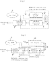
- Fig. 1 is a flow sheet showing the ammonia-engine system of the invention.
- An ammonia engine (2) is an engine that uses ammonia supplied from an NH 3 tank (1) as fuel and is driven by combustion of ammonia.
- An exhaust gas from the ammonia engine (2) is supplied to an ammonia oxidizing device (4).
- the exhaust gas from the ammonia engine (2) may be supplied directly to the ammonia oxidizing device (4) or may alternatively be passed through a line heater (3) before it is supplied to the ammonia oxidizing device (4).
- the line heater (3) is driven to heat the exhaust gas or not depends on the temperature of the exhaust gas. More specifically, the line heater (3) is an optional component in the invention. Because a combustion reaction of ammonia in the ammonia engine (2) is an exothermic reaction, the exhaust gas from the ammonia engine (2) has a temperature of 150°C or above when the ammonia engine (2) is driven normally.
- the exothermic reaction does not progress sufficiently in the ammonia engine (2) at the start-up of the ammonia engine (2). Accordingly, there is a case where the temperature of the exhaust gas does not reach 150°C. When the temperature of the exhaust gas does not reach 150°C, an oxidation reaction of ammonia in the ammonia oxidizing device (4) does not progress sufficiently. In such a case, the line heater (3) is driven in an auxiliary manner for the exhaust gas to have a temperature of 150°C or above.
- the ammonia oxidizing device (4) has a platinum-supported catalyst as an ammonia oxidation catalyst.
- the platinum-supported catalyst has, for example, a monolithic shape.
- An operating temperature of the platinum-supported catalyst is 150°C and oxidation of ammonia progresses because the exhaust gas supplied directly from the ammonia engine (2) or supplied after it is heated in the line heater (3) has a temperature of 150°C or above.
- An oxidation reaction of ammonia in the ammonia oxidizing device (4) is an exothermic reaction and a gas in the ammonia oxidizing device (4) reaches 290°C or above (preferably 340°C or above) due to this exothermic reaction.
- the gas having reached 290°C or above (preferably 340°C or above) in this manner is supplied to an exhaust gas introduction side of an ammonia cracking device (5).
- the ammonia cracking device (5) has, for example, the structure of a plate-type heat exchanger. Also, as a catalyst to crack ammonia, it has, for example, a ruthenium-supported catalyst.
- the ammonia cracking catalyst is filled in the ammonia cracking device (5) on an ammonia supply side or coated on a material surface on the ammonia supply side.
- a gas at 290°C or above (preferably at 340°C or above) is supplied from the ammonia oxidizing device (4) and ammonia is supplied from the NH 3 tank (1) to the ammonia supply side.
- the temperatures of the ammonia gas supplied therein and the ammonia cracking catalyst increase due to heat exchange between the exhaust gas and the ammonia gas, and ammonia supplied from the NH 3 tank (1) cracks to hydrogen and nitrogen by a catalytic action of the ammonia cracking catalyst.
- a hydrogen-containing ammonia-cracked gas thus produced is supplied to the ammonia engine (2) as a combustion improver for the ammonia engine (2).
- Example 1 heated air was used as a simulant gas of the exhaust gas from the ammonia engine.
- a honeycomb-shaped platinum catalyst obtained by coating a cordierite honeycomb substrate with a platinum-supported Al 2 O 3 catalyst, an amount of supported platinum: 2 g/L
- a ruthenium catalyst in a pellet form (having a diameter of 1 mm ⁇ ) (support: activated carbon with the use of a Ba compound as a promoter, amount of supported Ru: 5 wt%) was used as the ammonia cracking catalyst that the ammonia cracking device (5) has.
- the ammonia cracking catalyst was filled in the ammonia cracking device (5) on the ammonia supply side.
- a gas flow rate of the heated air was set to 10 NL/min and the temperature was raised from room temperature to 250°C.
- An amount of ammonia directly supplied to the ammonia cracking device (5) was adjusted to be 0.5 NL/min.
- the catalyst in each device was activated while varying an amount of ammonia supplied to the ammonia oxidizing device (4) and an ammonia cracking rate in the ammonia cracking device (5) was measured.
- the line heater (3) was not driven in Example 1.
- Example 1 The test result of Example 1 is set forth in Table 1 below, the test result of Example 2 in Table 2 below, and the test result of Comparative Example 1 in Table 3 below.
- Table 1 Temperature of Heated Air (°C) Ammonia Oxidizing Device Ammonia Cracking Device Ammonia Cracking Rate (%) Amount of Supplied Ammonia (NL/min) Inlet Temperature (°C) Outlet Temperature (°C) Inlet Temperature on Exhaust Gas Introduction Side (°C) Inlet Temperature of Cracking Catalyst (°C) 25 0.1 25 25 25 25 25 0 105 0.1 95 95 90 85 0 155 0.1 150 250 245 240 0 155 0.2 150 350 345 340 100 205 0.1 200 300 295 290 85 205 0.15 200 350 345 340 100 255 0.05 250 300 295 290 85 255 0.1 250 350 345 340 100 Table 2 Temperature of Heated Air (°C) Ammonia Oxidizing Device Ammonia Cracking Device Ammonia Crack
- production of heat in the ammonia oxidizing device (4) can be increased to over 340°C by adjusting an amount of ammonia to be supplied to the ammonia oxidizing device (4), which makes it possible to promote cracking of ammonia in the ammonia cracking device.
Landscapes
- Chemical & Material Sciences (AREA)
- Engineering & Computer Science (AREA)
- Organic Chemistry (AREA)
- Chemical Kinetics & Catalysis (AREA)
- Materials Engineering (AREA)
- Combustion & Propulsion (AREA)
- Mechanical Engineering (AREA)
- General Engineering & Computer Science (AREA)
- Health & Medical Sciences (AREA)
- Environmental & Geological Engineering (AREA)
- Biomedical Technology (AREA)
- Analytical Chemistry (AREA)
- General Chemical & Material Sciences (AREA)
- Oil, Petroleum & Natural Gas (AREA)
- General Health & Medical Sciences (AREA)
- Inorganic Chemistry (AREA)
- Catalysts (AREA)
- Exhaust Gas Treatment By Means Of Catalyst (AREA)
- Exhaust Gas After Treatment (AREA)
- Organic Low-Molecular-Weight Compounds And Preparation Thereof (AREA)
Claims (13)
- Ein Ammoniak-Motorsystem, umfassend:- einen Ammoniaktank,- einen Ammoniakmotor (2), der durch Verbrennung von Ammoniak angetrieben wird, wobei Ammoniak verwendet wird, welches aus dem Ammoniaktank als Kraftstoff zugeführt wird,- eine Ammoniakcrackvorrichtung (5), die einen Ammoniakcrackkatalysator aufweist, welcher Ammoniak crackt, um Wasserstoff zu erzeugen,- Mittel zum Zuführen von Ammoniak aus dem Ammoniaktank zum Ammoniakmotor (2),- Mittel zum Zuführen von Ammoniak aus dem Ammoniaktank zu der Ammoniakcrackvorrichtung (5),- Mittel zum Zuführen des wasserstoffhaltigen Ammoniakcrackgases, welches in der Ammoniakcrackvorrichtung (5) erzeugt wurde, zu dem Ammoniakmotor (2) als Verbrennungsverbesserer,wobei das Ammoniak-Motorsystem dadurch gekennzeichnet ist, dass es- eine Ammoniakoxidiervorrichtung (4), welche zwischen dem Ammoniakmotor (2) und der Ammoniakcrackvorrichtung (5) vorgesehen ist,- Mittel zum Zuführen eines ammoniakhaltigen Abgases von dem Ammoniakmotor (2) zu der Ammoniakoxidiervorrichtung (4), um Ammoniak in dem Abgas zu oxidieren, und- Mittel zum Zuführen des Abgases von dem ammoniakoxidierenden Motor (4) zu der abgaseinleitenden Seite der Ammoniakcrackvorrichtung (5) umfasst, um innerhalb der Ammoniakcrackvorrichtung (5) Wärme mit dem vom Ammoniaktank zugeführten Ammoniak und dem Ammoniakcrackkatalysator auszutauschen, und um deren Temperaturen zum Cracken von Ammoniak und Erzeugen von Wasserstoff zu erhöhen.
- Das Ammoniak-Motorsystem nach Anspruch 1, dadurch gekennzeichnet, dass die Ammoniakoxidiervorrichtung (4) einen platingestützten Katalysator aufweist.
- Das Ammoniak-Motorsystem nach Anspruch 2, dadurch gekennzeichnet, dass der platingestützte Katalysator eine monolithische Form besitzt.
- Das Ammoniak-Motorsystem nach einem der Ansprüche 1 bis 3, ferner umfassend eine Heizung (3), welche zwischen einem Ausgang des Ammoniakmotors (2) und der Ammoniakoxidiervorrichtung (4) vorgesehen ist.
- Das Ammoniak-Motorsystem nach einem der Ansprüche 1 bis 4, dadurch gekennzeichnet, dass die Ammoniakcrackvorrichtung (5) die Struktur eines Plattenwärmetauschers aufweist.
- Das Ammoniak-Motorsystem nach Anspruch 5, dadurch gekennzeichnet, dass der Ammoniakcrackkatalysator auf einer Ammoniak-Zuführseite in die Ammoniakcrackvorrichtung (5) eingefüllt ist, oder dass der Katalysator auf eine Oberfläche von einem Material auf der Ammoniak-Zuführseite der Ammoniakcrackvorrichtung (5) aufgebracht ist.
- Das Ammoniak-Motorsystem nach Anspruch 6, dadurch gekennzeichnet, dass der Ammoniakcrackkatalysator ein Katalysator ist, welcher Ruthenium, Rhodium, Nickel und/oder Eisen trägt.
- Ein Verfahren zum Betreiben eines Ammoniak-Motorsystems nach einem der Ansprüche 1 bis 7, wobei- das aus einem NH3-Tank (1) zugeführte Ammoniak einem Ammoniakmotor (2) als Kraftstoff zugeführt wird,- das Abgas des Ammoniakmotors (2) einer Ammoniakoxidiervorrichtung (4) zugeführt wird, in welcher das in dem Abgas enthaltene Ammoniak einer Oxidationsreaktion mit Sauerstoff unterworfen wird, um die Temperatur des Gases in der Ammoniakoxidiervorrichtung (4) zu erhöhen, und- das Gas von der Ammoniakoxidiervorrichtung (4) in eine Ammoniakcrackvorrichtung (5) eingeleitet wird, um Wärme innerhalb der Ammoniakcrackvorrichtung (5) mit dem vom Ammoniaktank zugeführten Ammoniak und dem Ammoniakcrackkatalysator auszutauschen, und um deren Temperatur zum Cracken von Ammoniak und Erzeugen von Wasserstoff zu erhöhen.
- Das Verfahren nach Anspruch 8, dadurch gekennzeichnet, dass eine Einlasstemperatur an einer Seite zur Abgaseinleitung der Ammoniakcrackvorrichtung (5) bei 290 °C oder darüber gehalten wird.
- Das Verfahren nach Anspruch 8 oder 9, dadurch gekennzeichnet, dass eine Einlasstemperatur der Ammoniakoxidiervorrichtung (4) bei 150 °C oder darüber gehalten wird.
- Das Verfahren nach einem der Ansprüche 8 bis 10, dadurch gekennzeichnet, dass ein Ammoniakgas ferner zu dem Abgas aus dem Ammoniakmotor (2) in dem Fall zugeleitet wird, wenn eine Einlasstemperatur an einer Stelle zur Abgaseinleitung der Ammoniakcrackvorrichtung (5) 300 °C oder darunter beträgt.
- Das Verfahren nach Anspruch 11, dadurch gekennzeichnet, dass das Ammoniakgas auch in dem Fall zugeleitet wird, wenn die Ammoniakkonzentration des Abgases von dem Ammoniakmotor (2) 3% oder weniger beträgt.
- Das Verfahren nach Anspruch 11 oder 12, dadurch gekennzeichnet, dass das Ammoniak, welches der Ammoniakoxidiervorrichtung zugeführt wird, nur in dem Fall durch eine Heizung (3) erwärmt wird, wenn die Einlasstemperatur der Ammoniakoxidiervorrichtung (4) 150 °C oder weniger beträgt.
Applications Claiming Priority (2)
| Application Number | Priority Date | Filing Date | Title |
|---|---|---|---|
| JP2008295476A JP5049947B2 (ja) | 2008-11-19 | 2008-11-19 | アンモニアエンジンシステム |
| PCT/JP2009/069601 WO2010058807A1 (ja) | 2008-11-19 | 2009-11-19 | アンモニアエンジンシステム |
Publications (3)
| Publication Number | Publication Date |
|---|---|
| EP2348209A1 EP2348209A1 (de) | 2011-07-27 |
| EP2348209A4 EP2348209A4 (de) | 2013-11-27 |
| EP2348209B1 true EP2348209B1 (de) | 2019-10-23 |
Family
ID=42198246
Family Applications (1)
| Application Number | Title | Priority Date | Filing Date |
|---|---|---|---|
| EP09827588.6A Not-in-force EP2348209B1 (de) | 2008-11-19 | 2009-11-19 | Ammoniakmotorensystem |
Country Status (5)
| Country | Link |
|---|---|
| US (1) | US9341111B2 (de) |
| EP (1) | EP2348209B1 (de) |
| JP (1) | JP5049947B2 (de) |
| CN (1) | CN102216588B (de) |
| WO (1) | WO2010058807A1 (de) |
Families Citing this family (47)
| Publication number | Priority date | Publication date | Assignee | Title |
|---|---|---|---|---|
| ITRM20080065A1 (it) * | 2008-02-06 | 2009-08-07 | Icomet S P A | Impianto di alimentazione di gpl/ammoniaca per motori ad iniezione diretta a benzina o diesel |
| JP5483705B2 (ja) * | 2009-03-17 | 2014-05-07 | 株式会社日本触媒 | 水素製造触媒およびそれを用いた水素製造方法 |
| CN103877983A (zh) | 2009-03-17 | 2014-06-25 | 株式会社日本触媒 | 制氢催化剂和使用该制氢催化剂的制氢方法 |
| JP5352323B2 (ja) * | 2009-04-07 | 2013-11-27 | トヨタ自動車株式会社 | 水素生成装置及び水素生成方法 |
| US8961923B2 (en) | 2010-05-27 | 2015-02-24 | Shawn Grannell | Autothermal ammonia cracker |
| JP2012066945A (ja) * | 2010-09-21 | 2012-04-05 | Hitachi Zosen Corp | アンモニアからの水素の製造方法 |
| US8561578B2 (en) * | 2010-12-30 | 2013-10-22 | Kabushiki Kaisha Toyota Chuo Kenkyusho | Hydrogen generator and internal combustion engine provided with hydrogen generator |
| JP5472203B2 (ja) * | 2011-05-25 | 2014-04-16 | 株式会社デンソー | コジェネレーションシステム |
| JP2012255420A (ja) * | 2011-06-10 | 2012-12-27 | Nippon Shokubai Co Ltd | ガスタービンシステム |
| JP6078056B2 (ja) * | 2012-05-15 | 2017-02-08 | 政晴 石本 | アンモニアエンジン |
| DE102013211509A1 (de) * | 2013-06-19 | 2014-12-24 | Behr Gmbh & Co. Kg | Verfahren und Vorrichtung zur Behandlung von Abgaskondensaten eines Verbrennungsmotors |
| CN104675580B (zh) * | 2015-02-13 | 2017-01-11 | 王海斌 | 一种新型汽车发动机氢氨混合燃料供应装置 |
| CN104675515B (zh) * | 2015-02-13 | 2017-03-01 | 王海斌 | 一种汽车发动机的汽油与氨双燃料供应装置 |
| JP6518539B2 (ja) * | 2015-07-17 | 2019-05-22 | 好朗 岩井 | 燃焼システム |
| GB2544552A (en) | 2015-11-20 | 2017-05-24 | Siemens Ag | A gas turbine system |
| AU2016398360B2 (en) * | 2016-03-14 | 2022-01-27 | Equinor Energy As | Ammonia cracking |
| MX359868B (es) | 2017-05-08 | 2018-09-25 | Monroy Sampieri Carlos | Sistema para captacion y monitoreo de agentes contaminantes atmosfericos. |
| CN107288780A (zh) * | 2017-06-09 | 2017-10-24 | 厦门大学 | 带氨裂解装置的动力机构 |
| DE102017011833A1 (de) * | 2017-12-21 | 2019-06-27 | Gerhard Wannemacher | Verfahren zur Abgasreinigung von mit Gemischen von Wasserstoff und Ammoniak betriebenen Kolbenmotoren |
| JP7163853B2 (ja) * | 2019-04-11 | 2022-11-01 | 株式会社豊田自動織機 | 改質システム及びエンジンシステム |
| JP7278544B2 (ja) | 2019-04-26 | 2023-05-22 | 国立大学法人東海国立大学機構 | 燃料改質装置及び燃料改質方法 |
| US11578686B2 (en) * | 2019-05-29 | 2023-02-14 | Kabushiki Kaisha Toyota Jidoshokki | Engine system |
| JP7176476B2 (ja) * | 2019-06-03 | 2022-11-22 | 株式会社豊田自動織機 | 改質システム |
| JP7259654B2 (ja) * | 2019-09-04 | 2023-04-18 | 株式会社豊田自動織機 | 水素利用システム |
| WO2021126935A1 (en) | 2019-12-19 | 2021-06-24 | Basf Corporation | Exhaust treatment system for ammonia-fueled vehicles |
| JP7374818B2 (ja) * | 2020-03-06 | 2023-11-07 | 三菱重工業株式会社 | アンモニアエンジン |
| JP7351270B2 (ja) * | 2020-07-31 | 2023-09-27 | 株式会社豊田自動織機 | エンジンシステム |
| JP2022103048A (ja) | 2020-12-25 | 2022-07-07 | 住友重機械マリンエンジニアリング株式会社 | ガス処理システム、及び船舶 |
| US11724245B2 (en) | 2021-08-13 | 2023-08-15 | Amogy Inc. | Integrated heat exchanger reactors for renewable fuel delivery systems |
| US11994061B2 (en) | 2021-05-14 | 2024-05-28 | Amogy Inc. | Methods for reforming ammonia |
| WO2022260526A1 (en) * | 2021-06-11 | 2022-12-15 | Wärtsilä Gas Solutions Norway AS | A system for removing ammonia from an ammonia-containing gas and a method for removing ammonia from an ammonia-containing gas |
| KR20240020274A (ko) | 2021-06-11 | 2024-02-14 | 아모지 인크. | 암모니아의 가공처리를 위한 시스템 및 방법 |
| US11539063B1 (en) | 2021-08-17 | 2022-12-27 | Amogy Inc. | Systems and methods for processing hydrogen |
| CN114483333B (zh) * | 2022-01-26 | 2022-12-20 | 武汉理工大学 | 双燃料发动机试验系统及方法 |
| CN114635786A (zh) * | 2022-02-14 | 2022-06-17 | 彭力上 | 一种热分解高压直喷型氨燃料的发动机 |
| EP4230853A1 (de) * | 2022-02-18 | 2023-08-23 | Johnson Matthey Public Limited Company | Ammoniakverbrennungsmotor |
| WO2023156787A1 (en) * | 2022-02-18 | 2023-08-24 | Johnson Matthey Public Limited Company | Ammonia-burning combustion engine |
| WO2023190385A1 (ja) * | 2022-03-29 | 2023-10-05 | 三菱重工業株式会社 | N2o分解触媒 |
| GB2618146A (en) * | 2022-04-29 | 2023-11-01 | Perkins Engines Co Ltd | Ammonia fuelled engine |
| WO2023244279A1 (en) | 2022-06-17 | 2023-12-21 | Basf Corporation | Exhaust treatment system for ammonia-fueled vehicles |
| CN115178187A (zh) * | 2022-06-29 | 2022-10-14 | 佛山仙湖实验室 | 一种车载高压型氨裂解反应器及工作系统 |
| JP2024009392A (ja) | 2022-07-11 | 2024-01-23 | ヤンマーホールディングス株式会社 | アンモニア分解システム、内燃機関システム及びアンモニア分解方法 |
| US11834334B1 (en) | 2022-10-06 | 2023-12-05 | Amogy Inc. | Systems and methods of processing ammonia |
| US11795055B1 (en) | 2022-10-21 | 2023-10-24 | Amogy Inc. | Systems and methods for processing ammonia |
| US11866328B1 (en) | 2022-10-21 | 2024-01-09 | Amogy Inc. | Systems and methods for processing ammonia |
| CN115750043A (zh) * | 2022-11-04 | 2023-03-07 | 东风商用车有限公司 | 用于氨燃料压燃内燃机的车载氨裂解制氢系统及控制方法 |
| JP7470914B1 (ja) | 2023-06-09 | 2024-04-19 | 兵庫県公立大学法人 | 水素貯蔵燃料及びその製造方法 |
Family Cites Families (18)
| Publication number | Priority date | Publication date | Assignee | Title |
|---|---|---|---|---|
| DE3606316A1 (de) * | 1986-02-27 | 1987-09-03 | Kernforschungsz Karlsruhe | Verfahren und vorrichtung zur dekontamination des abgases des brennstoffkreislaufs eines fusionsreaktors von tritium und/oder deuterium in chemisch gebundener form enthaltenden abgas-bestandteilen |
| JPH05332152A (ja) * | 1991-06-25 | 1993-12-14 | Koji Korematsu | アンモニア燃焼エンジン |
| US5976723A (en) * | 1997-03-12 | 1999-11-02 | Boffito; Claudio | Getter materials for cracking ammonia |
| GB9801564D0 (en) * | 1998-01-27 | 1998-03-25 | Ici Plc | Catalyst |
| GB9929332D0 (en) * | 1999-12-10 | 2000-02-02 | Boc Group Plc | Destruction of waste gas |
| AU2001263069A1 (en) * | 2000-05-12 | 2001-11-26 | Gradient Technology | Production of hydrogen by autothermic decomposition of ammonia |
| US7875089B2 (en) * | 2001-03-02 | 2011-01-25 | Intelligent Energy, Inc. | Ammonia-based hydrogen generation apparatus and method for using same |
| US7867300B2 (en) | 2001-03-02 | 2011-01-11 | Intelligent Energy, Inc. | Ammonia-based hydrogen generation apparatus and method for using same |
| US7922781B2 (en) | 2001-03-02 | 2011-04-12 | Chellappa Anand S | Hydrogen generation apparatus and method for using same |
| JP4705752B2 (ja) * | 2002-12-04 | 2011-06-22 | メタウォーター株式会社 | 廃棄物処理由来のアンモニアからのエネルギー回収方法 |
| JP2006219334A (ja) * | 2005-02-10 | 2006-08-24 | Kinzo Ri | 水素生成装置 |
| JP4800691B2 (ja) * | 2005-07-19 | 2011-10-26 | 本田技研工業株式会社 | 燃料電池の改質装置 |
| JP2007132202A (ja) * | 2005-11-08 | 2007-05-31 | Hino Motors Ltd | 排気昇温装置 |
| JP4737023B2 (ja) | 2006-10-04 | 2011-07-27 | 株式会社日立製作所 | 水素エンジンシステム |
| GB2493865B (en) * | 2007-04-04 | 2013-06-26 | Worleyparsons Group Inc | Ammonia destruction methods for use in a Claus tail gas treating unit |
| US8171724B2 (en) * | 2007-05-02 | 2012-05-08 | Ford Global Technologies, Llc | Vehicle-based strategy for removing urea deposits from an SCR catalyst |
| US8272353B2 (en) * | 2008-02-19 | 2012-09-25 | University Of Ontario Institute Of Technology | Apparatus for using ammonia as a sustainable fuel, refrigerant and NOx reduction agent |
| JP5352323B2 (ja) * | 2009-04-07 | 2013-11-27 | トヨタ自動車株式会社 | 水素生成装置及び水素生成方法 |
-
2008
- 2008-11-19 JP JP2008295476A patent/JP5049947B2/ja active Active
-
2009
- 2009-11-19 EP EP09827588.6A patent/EP2348209B1/de not_active Not-in-force
- 2009-11-19 WO PCT/JP2009/069601 patent/WO2010058807A1/ja active Application Filing
- 2009-11-19 US US13/130,201 patent/US9341111B2/en active Active
- 2009-11-19 CN CN200980146125.2A patent/CN102216588B/zh active Active
Non-Patent Citations (1)
| Title |
|---|
| None * |
Also Published As
| Publication number | Publication date |
|---|---|
| CN102216588B (zh) | 2016-10-05 |
| EP2348209A1 (de) | 2011-07-27 |
| WO2010058807A1 (ja) | 2010-05-27 |
| US9341111B2 (en) | 2016-05-17 |
| JP5049947B2 (ja) | 2012-10-17 |
| US20110283960A1 (en) | 2011-11-24 |
| CN102216588A (zh) | 2011-10-12 |
| JP2010121509A (ja) | 2010-06-03 |
| EP2348209A4 (de) | 2013-11-27 |
Similar Documents
| Publication | Publication Date | Title |
|---|---|---|
| EP2348209B1 (de) | Ammoniakmotorensystem | |
| JP5352323B2 (ja) | 水素生成装置及び水素生成方法 | |
| US8722011B2 (en) | Method of producing hydrogen from ammonia | |
| JP5097160B2 (ja) | 燃料改質装置 | |
| JP5136905B2 (ja) | 炭化水素燃料から水素を生成するための方法 | |
| JP2003506306A (ja) | コンパクト反応器 | |
| JP3759406B2 (ja) | メタノール改質触媒、メタノール改質装置及びメタノール改質方法 | |
| WO2001047802A1 (fr) | Dispositif de formation d'hydrogene | |
| JP2009504558A5 (de) | ||
| FI3878806T3 (fi) | Menetelmä vedyn tai vetypitoisten polttoaineiden valmistamiseksi katalyyttisella ammoniakin hajotuksella | |
| KR100719486B1 (ko) | 마이크로 연소/개질반응기 | |
| CN1131322C (zh) | 产生热处理气氛的装置 | |
| CN107925104A (zh) | 包含高级烃还原单元的固体氧化物燃料电池系统 | |
| JP4029575B2 (ja) | 燃料改質装置 | |
| JP5231825B2 (ja) | 燃料改質装置 | |
| JP2002104808A (ja) | 燃料改質方法 | |
| JP5717993B2 (ja) | 改質装置及びその製造方法 | |
| JP2003083515A (ja) | 燃焼装置 | |
| JP4057581B2 (ja) | 触媒性燃焼のための触媒材質およびその応用プロセス | |
| KR20060016986A (ko) | 연료의 부분 산화 개질 반응용 촉매, 이를 이용한 연료개질 장치 및 연료 개질 방법 | |
| JP2021014393A (ja) | 改質システム | |
| JP4266070B2 (ja) | 燃料改質装置 | |
| KR100580010B1 (ko) | 가솔린 개질용 촉매의 제조 방법 | |
| KR20060069399A (ko) | 연료의 부분 산화 개질 반응용 촉매 | |
| JP2003040604A (ja) | 水素製造方法および装置 |
Legal Events
| Date | Code | Title | Description |
|---|---|---|---|
| PUAI | Public reference made under article 153(3) epc to a published international application that has entered the european phase |
Free format text: ORIGINAL CODE: 0009012 |
|
| 17P | Request for examination filed |
Effective date: 20110513 |
|
| AK | Designated contracting states |
Kind code of ref document: A1 Designated state(s): AT BE BG CH CY CZ DE DK EE ES FI FR GB GR HR HU IE IS IT LI LT LU LV MC MK MT NL NO PL PT RO SE SI SK SM TR |
|
| AX | Request for extension of the european patent |
Extension state: AL BA RS |
|
| DAX | Request for extension of the european patent (deleted) | ||
| RAP1 | Party data changed (applicant data changed or rights of an application transferred) |
Owner name: HITACHI ZOSEN CORPORATION Owner name: TOYOTA JIDOSHA KABUSHIKI KAISHA |
|
| A4 | Supplementary search report drawn up and despatched |
Effective date: 20131028 |
|
| RIC1 | Information provided on ipc code assigned before grant |
Ipc: B01J 35/04 20060101ALI20131022BHEP Ipc: F02M 25/12 20060101ALI20131022BHEP Ipc: B01J 23/46 20060101ALI20131022BHEP Ipc: B01D 53/00 20060101ALI20131022BHEP Ipc: F02M 21/02 20060101ALI20131022BHEP Ipc: F02B 43/10 20060101ALI20131022BHEP Ipc: C01B 3/04 20060101AFI20131022BHEP Ipc: F02M 27/02 20060101ALI20131022BHEP Ipc: B01J 23/42 20060101ALI20131022BHEP |
|
| STAA | Information on the status of an ep patent application or granted ep patent |
Free format text: STATUS: EXAMINATION IS IN PROGRESS |
|
| 17Q | First examination report despatched |
Effective date: 20170207 |
|
| REG | Reference to a national code |
Ref country code: DE Ref legal event code: R079 Ref document number: 602009060253 Country of ref document: DE Free format text: PREVIOUS MAIN CLASS: F02B0043100000 Ipc: C01B0003040000 |
|
| GRAP | Despatch of communication of intention to grant a patent |
Free format text: ORIGINAL CODE: EPIDOSNIGR1 |
|
| STAA | Information on the status of an ep patent application or granted ep patent |
Free format text: STATUS: GRANT OF PATENT IS INTENDED |
|
| RIC1 | Information provided on ipc code assigned before grant |
Ipc: B01J 23/46 20060101ALI20190226BHEP Ipc: F02M 25/12 20060101ALI20190226BHEP Ipc: F02B 43/10 20060101ALI20190226BHEP Ipc: B01D 53/94 20060101ALI20190226BHEP Ipc: B01J 23/74 20060101ALI20190226BHEP Ipc: B01J 35/04 20060101ALI20190226BHEP Ipc: C01B 3/04 20060101AFI20190226BHEP Ipc: B01J 23/42 20060101ALI20190226BHEP Ipc: B01J 23/58 20060101ALI20190226BHEP |
|
| INTG | Intention to grant announced |
Effective date: 20190402 |
|
| GRAS | Grant fee paid |
Free format text: ORIGINAL CODE: EPIDOSNIGR3 |
|
| GRAJ | Information related to disapproval of communication of intention to grant by the applicant or resumption of examination proceedings by the epo deleted |
Free format text: ORIGINAL CODE: EPIDOSDIGR1 |
|
| GRAL | Information related to payment of fee for publishing/printing deleted |
Free format text: ORIGINAL CODE: EPIDOSDIGR3 |
|
| STAA | Information on the status of an ep patent application or granted ep patent |
Free format text: STATUS: EXAMINATION IS IN PROGRESS |
|
| GRAP | Despatch of communication of intention to grant a patent |
Free format text: ORIGINAL CODE: EPIDOSNIGR1 |
|
| STAA | Information on the status of an ep patent application or granted ep patent |
Free format text: STATUS: GRANT OF PATENT IS INTENDED |
|
| INTC | Intention to grant announced (deleted) | ||
| GRAA | (expected) grant |
Free format text: ORIGINAL CODE: 0009210 |
|
| STAA | Information on the status of an ep patent application or granted ep patent |
Free format text: STATUS: THE PATENT HAS BEEN GRANTED |
|
| INTG | Intention to grant announced |
Effective date: 20190906 |
|
| AK | Designated contracting states |
Kind code of ref document: B1 Designated state(s): AT BE BG CH CY CZ DE DK EE ES FI FR GB GR HR HU IE IS IT LI LT LU LV MC MK MT NL NO PL PT RO SE SI SK SM TR |
|
| REG | Reference to a national code |
Ref country code: GB Ref legal event code: FG4D |
|
| REG | Reference to a national code |
Ref country code: CH Ref legal event code: EP |
|
| REG | Reference to a national code |
Ref country code: IE Ref legal event code: FG4D |
|
| REG | Reference to a national code |
Ref country code: DE Ref legal event code: R096 Ref document number: 602009060253 Country of ref document: DE |
|
| REG | Reference to a national code |
Ref country code: AT Ref legal event code: REF Ref document number: 1193443 Country of ref document: AT Kind code of ref document: T Effective date: 20191115 |
|
| REG | Reference to a national code |
Ref country code: NL Ref legal event code: MP Effective date: 20191023 |
|
| REG | Reference to a national code |
Ref country code: LT Ref legal event code: MG4D |
|
| PG25 | Lapsed in a contracting state [announced via postgrant information from national office to epo] |
Ref country code: PT Free format text: LAPSE BECAUSE OF FAILURE TO SUBMIT A TRANSLATION OF THE DESCRIPTION OR TO PAY THE FEE WITHIN THE PRESCRIBED TIME-LIMIT Effective date: 20200224 Ref country code: FI Free format text: LAPSE BECAUSE OF FAILURE TO SUBMIT A TRANSLATION OF THE DESCRIPTION OR TO PAY THE FEE WITHIN THE PRESCRIBED TIME-LIMIT Effective date: 20191023 Ref country code: SE Free format text: LAPSE BECAUSE OF FAILURE TO SUBMIT A TRANSLATION OF THE DESCRIPTION OR TO PAY THE FEE WITHIN THE PRESCRIBED TIME-LIMIT Effective date: 20191023 Ref country code: NL Free format text: LAPSE BECAUSE OF FAILURE TO SUBMIT A TRANSLATION OF THE DESCRIPTION OR TO PAY THE FEE WITHIN THE PRESCRIBED TIME-LIMIT Effective date: 20191023 Ref country code: PL Free format text: LAPSE BECAUSE OF FAILURE TO SUBMIT A TRANSLATION OF THE DESCRIPTION OR TO PAY THE FEE WITHIN THE PRESCRIBED TIME-LIMIT Effective date: 20191023 Ref country code: ES Free format text: LAPSE BECAUSE OF FAILURE TO SUBMIT A TRANSLATION OF THE DESCRIPTION OR TO PAY THE FEE WITHIN THE PRESCRIBED TIME-LIMIT Effective date: 20191023 Ref country code: LT Free format text: LAPSE BECAUSE OF FAILURE TO SUBMIT A TRANSLATION OF THE DESCRIPTION OR TO PAY THE FEE WITHIN THE PRESCRIBED TIME-LIMIT Effective date: 20191023 Ref country code: NO Free format text: LAPSE BECAUSE OF FAILURE TO SUBMIT A TRANSLATION OF THE DESCRIPTION OR TO PAY THE FEE WITHIN THE PRESCRIBED TIME-LIMIT Effective date: 20200123 Ref country code: GR Free format text: LAPSE BECAUSE OF FAILURE TO SUBMIT A TRANSLATION OF THE DESCRIPTION OR TO PAY THE FEE WITHIN THE PRESCRIBED TIME-LIMIT Effective date: 20200124 Ref country code: BG Free format text: LAPSE BECAUSE OF FAILURE TO SUBMIT A TRANSLATION OF THE DESCRIPTION OR TO PAY THE FEE WITHIN THE PRESCRIBED TIME-LIMIT Effective date: 20200123 Ref country code: LV Free format text: LAPSE BECAUSE OF FAILURE TO SUBMIT A TRANSLATION OF THE DESCRIPTION OR TO PAY THE FEE WITHIN THE PRESCRIBED TIME-LIMIT Effective date: 20191023 |
|
| PG25 | Lapsed in a contracting state [announced via postgrant information from national office to epo] |
Ref country code: IS Free format text: LAPSE BECAUSE OF FAILURE TO SUBMIT A TRANSLATION OF THE DESCRIPTION OR TO PAY THE FEE WITHIN THE PRESCRIBED TIME-LIMIT Effective date: 20200224 Ref country code: HR Free format text: LAPSE BECAUSE OF FAILURE TO SUBMIT A TRANSLATION OF THE DESCRIPTION OR TO PAY THE FEE WITHIN THE PRESCRIBED TIME-LIMIT Effective date: 20191023 |
|
| REG | Reference to a national code |
Ref country code: CH Ref legal event code: PL |
|
| REG | Reference to a national code |
Ref country code: DE Ref legal event code: R097 Ref document number: 602009060253 Country of ref document: DE |
|
| PG2D | Information on lapse in contracting state deleted |
Ref country code: IS |
|
| PG25 | Lapsed in a contracting state [announced via postgrant information from national office to epo] |
Ref country code: DK Free format text: LAPSE BECAUSE OF FAILURE TO SUBMIT A TRANSLATION OF THE DESCRIPTION OR TO PAY THE FEE WITHIN THE PRESCRIBED TIME-LIMIT Effective date: 20191023 Ref country code: CH Free format text: LAPSE BECAUSE OF NON-PAYMENT OF DUE FEES Effective date: 20191130 Ref country code: MC Free format text: LAPSE BECAUSE OF FAILURE TO SUBMIT A TRANSLATION OF THE DESCRIPTION OR TO PAY THE FEE WITHIN THE PRESCRIBED TIME-LIMIT Effective date: 20191023 Ref country code: LI Free format text: LAPSE BECAUSE OF NON-PAYMENT OF DUE FEES Effective date: 20191130 Ref country code: CZ Free format text: LAPSE BECAUSE OF FAILURE TO SUBMIT A TRANSLATION OF THE DESCRIPTION OR TO PAY THE FEE WITHIN THE PRESCRIBED TIME-LIMIT Effective date: 20191023 Ref country code: RO Free format text: LAPSE BECAUSE OF FAILURE TO SUBMIT A TRANSLATION OF THE DESCRIPTION OR TO PAY THE FEE WITHIN THE PRESCRIBED TIME-LIMIT Effective date: 20191023 Ref country code: LU Free format text: LAPSE BECAUSE OF NON-PAYMENT OF DUE FEES Effective date: 20191119 Ref country code: EE Free format text: LAPSE BECAUSE OF FAILURE TO SUBMIT A TRANSLATION OF THE DESCRIPTION OR TO PAY THE FEE WITHIN THE PRESCRIBED TIME-LIMIT Effective date: 20191023 Ref country code: IS Free format text: LAPSE BECAUSE OF FAILURE TO SUBMIT A TRANSLATION OF THE DESCRIPTION OR TO PAY THE FEE WITHIN THE PRESCRIBED TIME-LIMIT Effective date: 20200223 |
|
| REG | Reference to a national code |
Ref country code: AT Ref legal event code: MK05 Ref document number: 1193443 Country of ref document: AT Kind code of ref document: T Effective date: 20191023 |
|
| REG | Reference to a national code |
Ref country code: BE Ref legal event code: MM Effective date: 20191130 |
|
| PLBE | No opposition filed within time limit |
Free format text: ORIGINAL CODE: 0009261 |
|
| STAA | Information on the status of an ep patent application or granted ep patent |
Free format text: STATUS: NO OPPOSITION FILED WITHIN TIME LIMIT |
|
| PG25 | Lapsed in a contracting state [announced via postgrant information from national office to epo] |
Ref country code: IT Free format text: LAPSE BECAUSE OF FAILURE TO SUBMIT A TRANSLATION OF THE DESCRIPTION OR TO PAY THE FEE WITHIN THE PRESCRIBED TIME-LIMIT Effective date: 20191023 Ref country code: SK Free format text: LAPSE BECAUSE OF FAILURE TO SUBMIT A TRANSLATION OF THE DESCRIPTION OR TO PAY THE FEE WITHIN THE PRESCRIBED TIME-LIMIT Effective date: 20191023 Ref country code: SM Free format text: LAPSE BECAUSE OF FAILURE TO SUBMIT A TRANSLATION OF THE DESCRIPTION OR TO PAY THE FEE WITHIN THE PRESCRIBED TIME-LIMIT Effective date: 20191023 |
|
| 26N | No opposition filed |
Effective date: 20200724 |
|
| PG25 | Lapsed in a contracting state [announced via postgrant information from national office to epo] |
Ref country code: IE Free format text: LAPSE BECAUSE OF NON-PAYMENT OF DUE FEES Effective date: 20191119 |
|
| PG25 | Lapsed in a contracting state [announced via postgrant information from national office to epo] |
Ref country code: BE Free format text: LAPSE BECAUSE OF NON-PAYMENT OF DUE FEES Effective date: 20191130 Ref country code: SI Free format text: LAPSE BECAUSE OF FAILURE TO SUBMIT A TRANSLATION OF THE DESCRIPTION OR TO PAY THE FEE WITHIN THE PRESCRIBED TIME-LIMIT Effective date: 20191023 Ref country code: AT Free format text: LAPSE BECAUSE OF FAILURE TO SUBMIT A TRANSLATION OF THE DESCRIPTION OR TO PAY THE FEE WITHIN THE PRESCRIBED TIME-LIMIT Effective date: 20191023 |
|
| PG25 | Lapsed in a contracting state [announced via postgrant information from national office to epo] |
Ref country code: CY Free format text: LAPSE BECAUSE OF FAILURE TO SUBMIT A TRANSLATION OF THE DESCRIPTION OR TO PAY THE FEE WITHIN THE PRESCRIBED TIME-LIMIT Effective date: 20191023 |
|
| PG25 | Lapsed in a contracting state [announced via postgrant information from national office to epo] |
Ref country code: MT Free format text: LAPSE BECAUSE OF FAILURE TO SUBMIT A TRANSLATION OF THE DESCRIPTION OR TO PAY THE FEE WITHIN THE PRESCRIBED TIME-LIMIT Effective date: 20191023 Ref country code: HU Free format text: LAPSE BECAUSE OF FAILURE TO SUBMIT A TRANSLATION OF THE DESCRIPTION OR TO PAY THE FEE WITHIN THE PRESCRIBED TIME-LIMIT; INVALID AB INITIO Effective date: 20091119 |
|
| PGFP | Annual fee paid to national office [announced via postgrant information from national office to epo] |
Ref country code: GB Payment date: 20210930 Year of fee payment: 13 |
|
| PGFP | Annual fee paid to national office [announced via postgrant information from national office to epo] |
Ref country code: FR Payment date: 20211109 Year of fee payment: 13 Ref country code: DE Payment date: 20210929 Year of fee payment: 13 |
|
| PG25 | Lapsed in a contracting state [announced via postgrant information from national office to epo] |
Ref country code: TR Free format text: LAPSE BECAUSE OF FAILURE TO SUBMIT A TRANSLATION OF THE DESCRIPTION OR TO PAY THE FEE WITHIN THE PRESCRIBED TIME-LIMIT Effective date: 20191023 |
|
| PG25 | Lapsed in a contracting state [announced via postgrant information from national office to epo] |
Ref country code: MK Free format text: LAPSE BECAUSE OF FAILURE TO SUBMIT A TRANSLATION OF THE DESCRIPTION OR TO PAY THE FEE WITHIN THE PRESCRIBED TIME-LIMIT Effective date: 20191023 |
|
| REG | Reference to a national code |
Ref country code: DE Ref legal event code: R119 Ref document number: 602009060253 Country of ref document: DE |
|
| GBPC | Gb: european patent ceased through non-payment of renewal fee |
Effective date: 20221119 |
|
| PG25 | Lapsed in a contracting state [announced via postgrant information from national office to epo] |
Ref country code: GB Free format text: LAPSE BECAUSE OF NON-PAYMENT OF DUE FEES Effective date: 20221119 Ref country code: DE Free format text: LAPSE BECAUSE OF NON-PAYMENT OF DUE FEES Effective date: 20230601 |
|
| PG25 | Lapsed in a contracting state [announced via postgrant information from national office to epo] |
Ref country code: FR Free format text: LAPSE BECAUSE OF NON-PAYMENT OF DUE FEES Effective date: 20221130 |