EP2344765B1 - Hermetische anschlussklemme für einen verdichter - Google Patents
Hermetische anschlussklemme für einen verdichter Download PDFInfo
- Publication number
- EP2344765B1 EP2344765B1 EP08767658.1A EP08767658A EP2344765B1 EP 2344765 B1 EP2344765 B1 EP 2344765B1 EP 08767658 A EP08767658 A EP 08767658A EP 2344765 B1 EP2344765 B1 EP 2344765B1
- Authority
- EP
- European Patent Office
- Prior art keywords
- thickness
- compressor
- shell
- projection
- leg portion
- Prior art date
- Legal status (The legal status is an assumption and is not a legal conclusion. Google has not performed a legal analysis and makes no representation as to the accuracy of the status listed.)
- Active
Links
Images


Classifications
-
- F—MECHANICAL ENGINEERING; LIGHTING; HEATING; WEAPONS; BLASTING
- F04—POSITIVE - DISPLACEMENT MACHINES FOR LIQUIDS; PUMPS FOR LIQUIDS OR ELASTIC FLUIDS
- F04C—ROTARY-PISTON, OR OSCILLATING-PISTON, POSITIVE-DISPLACEMENT MACHINES FOR LIQUIDS; ROTARY-PISTON, OR OSCILLATING-PISTON, POSITIVE-DISPLACEMENT PUMPS
- F04C23/00—Combinations of two or more pumps, each being of rotary-piston or oscillating-piston type, specially adapted for elastic fluids; Pumping installations specially adapted for elastic fluids; Multi-stage pumps specially adapted for elastic fluids
- F04C23/008—Hermetic pumps
-
- F—MECHANICAL ENGINEERING; LIGHTING; HEATING; WEAPONS; BLASTING
- F01—MACHINES OR ENGINES IN GENERAL; ENGINE PLANTS IN GENERAL; STEAM ENGINES
- F01C—ROTARY-PISTON OR OSCILLATING-PISTON MACHINES OR ENGINES
- F01C1/00—Rotary-piston machines or engines
- F01C1/08—Rotary-piston machines or engines of intermeshing engagement type, i.e. with engagement of co- operating members similar to that of toothed gearing
- F01C1/10—Rotary-piston machines or engines of intermeshing engagement type, i.e. with engagement of co- operating members similar to that of toothed gearing of internal-axis type with the outer member having more teeth or tooth-equivalents, e.g. rollers, than the inner member
-
- F—MECHANICAL ENGINEERING; LIGHTING; HEATING; WEAPONS; BLASTING
- F04—POSITIVE - DISPLACEMENT MACHINES FOR LIQUIDS; PUMPS FOR LIQUIDS OR ELASTIC FLUIDS
- F04C—ROTARY-PISTON, OR OSCILLATING-PISTON, POSITIVE-DISPLACEMENT MACHINES FOR LIQUIDS; ROTARY-PISTON, OR OSCILLATING-PISTON, POSITIVE-DISPLACEMENT PUMPS
- F04C18/00—Rotary-piston pumps specially adapted for elastic fluids
- F04C18/02—Rotary-piston pumps specially adapted for elastic fluids of arcuate-engagement type, i.e. with circular translatory movement of co-operating members, each member having the same number of teeth or tooth-equivalents
- F04C18/0207—Rotary-piston pumps specially adapted for elastic fluids of arcuate-engagement type, i.e. with circular translatory movement of co-operating members, each member having the same number of teeth or tooth-equivalents both members having co-operating elements in spiral form
- F04C18/0215—Rotary-piston pumps specially adapted for elastic fluids of arcuate-engagement type, i.e. with circular translatory movement of co-operating members, each member having the same number of teeth or tooth-equivalents both members having co-operating elements in spiral form where only one member is moving
-
- F—MECHANICAL ENGINEERING; LIGHTING; HEATING; WEAPONS; BLASTING
- F04—POSITIVE - DISPLACEMENT MACHINES FOR LIQUIDS; PUMPS FOR LIQUIDS OR ELASTIC FLUIDS
- F04C—ROTARY-PISTON, OR OSCILLATING-PISTON, POSITIVE-DISPLACEMENT MACHINES FOR LIQUIDS; ROTARY-PISTON, OR OSCILLATING-PISTON, POSITIVE-DISPLACEMENT PUMPS
- F04C2240/00—Components
- F04C2240/30—Casings or housings
-
- F—MECHANICAL ENGINEERING; LIGHTING; HEATING; WEAPONS; BLASTING
- F04—POSITIVE - DISPLACEMENT MACHINES FOR LIQUIDS; PUMPS FOR LIQUIDS OR ELASTIC FLUIDS
- F04C—ROTARY-PISTON, OR OSCILLATING-PISTON, POSITIVE-DISPLACEMENT MACHINES FOR LIQUIDS; ROTARY-PISTON, OR OSCILLATING-PISTON, POSITIVE-DISPLACEMENT PUMPS
- F04C2240/00—Components
- F04C2240/80—Other components
- F04C2240/803—Electric connectors or cables; Fittings therefor
-
- H—ELECTRICITY
- H01—ELECTRIC ELEMENTS
- H01R—ELECTRICALLY-CONDUCTIVE CONNECTIONS; STRUCTURAL ASSOCIATIONS OF A PLURALITY OF MUTUALLY-INSULATED ELECTRICAL CONNECTING ELEMENTS; COUPLING DEVICES; CURRENT COLLECTORS
- H01R13/00—Details of coupling devices of the kinds covered by groups H01R12/70 or H01R24/00 - H01R33/00
- H01R13/46—Bases; Cases
- H01R13/52—Dustproof, splashproof, drip-proof, waterproof, or flameproof cases
- H01R13/5202—Sealing means between parts of housing or between housing part and a wall, e.g. sealing rings
-
- H—ELECTRICITY
- H01—ELECTRIC ELEMENTS
- H01R—ELECTRICALLY-CONDUCTIVE CONNECTIONS; STRUCTURAL ASSOCIATIONS OF A PLURALITY OF MUTUALLY-INSULATED ELECTRICAL CONNECTING ELEMENTS; COUPLING DEVICES; CURRENT COLLECTORS
- H01R13/00—Details of coupling devices of the kinds covered by groups H01R12/70 or H01R24/00 - H01R33/00
- H01R13/73—Means for mounting coupling parts to apparatus or structures, e.g. to a wall
- H01R13/74—Means for mounting coupling parts in openings of a panel
Definitions
- the present disclosure relates to a hermetic terminal for a compressor.
- Hermetic terminals may be used to provide an electrical connection between electrical components in the interior of a compressor and an exterior power supply or other external electrical device. Hermetic terminals are generally provided in an aperture on the compressor shell.
- WO 2007/005981 A1 discloses a compressor according to the pre-characterizing portion of claim 1.
- a thickness of the projection may be approximately equal to a thickness of the housing.
- a ratio of a thickness of the projection compared to a thickness of the housing may be between 0.5 - 0.75.
- a ratio of a thickness of the projection compared to a thickness of the wall and the leg portion may be between 1.5 - 2.0.
- a ratio of a thickness of the projection compared to a thickness of the wall and the leg portion may be between 2.0 - 3.0.
- the projection may be secured to the inner surface approximately a shell thickness away from the aperture.
- the projection may be secured to the inner surface at least a shell thickness away from the aperture.
- the wall may merge into the leg portion at a joint having a radius of curvature. Radii of the radius of curvature may have a length of about half a thickness of the wall or the leg portion.
- a total length of the wall and the leg portion may be approximately four times a thickness of the wall or the leg portion.
- the projection may be defined by sidewalls angled relative to the leg portion.
- the sidewalls may terminate at an apex portion that is substantially parallel to the leg portion.
- a lip portion may be provided outboard the projection.
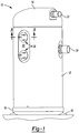
- a compressor 10 is shown to include a hermetic shell 12 having a welded cap 14 at a top portion and a base 16 having a plurality of feet 18 welded at a bottom portion.
- Cap 14 and base 16 may be fitted to shell 12 such that an interior volume 20 of compressor 10 is defined.
- Cap 14 may be provided with a discharge fitting 22 and an inlet fitting 24 may be disposed generally between cap 14 and base 16.
- a single or plurality of hermetic terminals 26 may be disposed on a side of compressor shell 12.
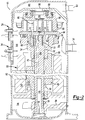
- a drive shaft or crankshaft 28 having an eccentric pin 30 at an upper end thereof is rotatably journaled in a bearing 32 in the main bearing housing 34.
- a second bearing 36 is disposed in the lower bearing housing 38.
- the crankshaft 28 has a relatively large diameter concentric bore 40 which communicates with a radially outwardly inclined smaller diameter bore 42 that extends to the end of the crankshaft 28.
- a stirrer 44 may be disposed within the bore 40.
- the lower portion of the interior shell 12 defines an oil sump 46 that may be filled with lubricating oil to a level slightly below the lower end of the rotor 48, and the bore 40 may act as a pump to pump lubricating fluid into the smaller diameter bore 42 and ultimately to all of the various portions of the compressor 10 which may require lubrication.
- the crankshaft 28 may be rotatively driven by an electric motor 50 including a stator 52 and windings 54 passing therethrough.
- the rotor 48 may be press fitted on the crankshaft 28 and may have upper and lower counterweights 56 and 58, respectively.
- An upper surface 60 of the main bearing housing 34 may be provided with a flat thrust bearing surface 62 on which an orbiting scroll member 64 may be disposed having the usual spiral vane or wrap 66 on the upper surface thereof.
- a cylindrical hub 68 may downwardly project from the lower surface of orbiting scroll member 64 which has a journal bearing 70 and drive bushing 72.
- Crank pin 30 may have a flat 74 on one surface that drivingly engages a flat surface formed in a portion of the drive bushing 72 to provide a radially compliant driving arrangement.
- An Oldham coupling 78 may be provided positioned between the orbiting scroll member 64 and the main bearing housing 34 and may be keyed to the orbiting scroll member 64 and a non-orbiting scroll member 80 to prevent rotational movement of the orbiting scroll member 64.
- Non-orbiting scroll member 80 also includes a wrap 82 positioned in meshing engagement with the wrap 66 of the orbiting scroll member 64.
- Non-orbiting scroll member 80 may have a centrally disposed discharge passage 84, which communicates with an upwardly open recess 86 formed in a partition 88 that separates the interior volume 20 of the compressor 10 into a suction chamber 90 and a discharge chamber 92.
- Recess 86 may be in fluid communication with discharge fitting 22 such that a compressed fluid exits compressor 10.
- hermetic terminal assemblies 26 are generally disposed in aperture 93 formed in compressor shell 12.
- Aperture 93 may be defined by a peripheral surface 97 that extends between an outer surface 99 of shell 12 and an inner surface 102 of shell 12.
- Terminal assemblies 26 provide an electrical pathway for compressor 10, and may be electrically connected to motor 50 or sensors (not shown).
- Exemplary sensors include motor-based sensors, oil level sensors, pressure sensors, temperature sensors, and the like. Regardless, any electrical component within compressor 10 that may require an electrical connection may be in communication with terminal assemblies 26.
- Terminal assemblies 26 generally include a cup-shaped housing 94 that houses a plurality of terminals 96.
- Cup-shaped housing 94 extends through aperture 93 along peripheral surface 97.
- Surrounding cup-shaped housing 94 may be an annular flange 98 that may be integral with cup-shaped housing 94.
- Cup-shaped housing 94 and flange 98 may be formed of steel or some other rigid material so that ends 100 of annular flange 98 may be welded to an inner surface 102 of compressor shell 12.
- shell 12 may be provided with a surface 95 that is coined flat.
- Flat surface 95 provides a surface that better aligns with annular flange 98.
- Each terminal 96 of hermetic terminal assembly 26 may include a stainless steel inner core 104 that passes through cup-shaped housing 94.
- a first or primary insulating member 106 that may be formed of, for example, glass seals a through 108 hole in cup-shaped housing 94 through which terminals 96 pass.
- Formed inside cup-shaped member i.e., on a side of terminal assembly 26 adjacent interior volume 20
- a second or secondary insulating material 110 Formed inside cup-shaped member (i.e., on a side of terminal assembly 26 adjacent interior volume 20) is a second or secondary insulating material 110 that may be formed of, for example, a ceramic material.
- An outer surface 112 of the cup-shaped housing 94 may be at least partially covered by a rubber membrane 114.
- annular flange 98 extends generally perpendicular to walls 118 of cup-shaped housing 94.
- the strength of the hermetic seal between terminal assembly 26 and shell 12 may be enhanced.
- the joint between aperture 93 and terminal assembly 26 may create a weakness in the overall strength of compressor shell 12 due to localized bending caused by discontinuity of the joint.
- Pressure within compressor 10 fluctuates to a great extent during operation. Pressure increases may cause shell 12 to expand in both axially and radially during operation of compressor 10. Simultaneously, aperture 93 may expand axially and radially.
- terminal 26' may include a cup-shaped housing 94' extends through aperture 93 along peripheral surface 97.
- Surrounding cup-shaped housing 94' may be an annular flange 98' that may be integral with cup-shaped housing 94 and angled outwardly therefrom.
- Cup- shaped housing 94' and flange 98' may be formed of steel or some other rigid material so that annular flange 98' may be welded to a peripheral surface 97 of compressor shell 12 by weld line 116.
- weld line 116 between shell 12 and terminal assembly 26' is located at the edge of the aperture 93 between outer surface 99 of shell 12 and peripheral surface 97.
- high localized stress and strain concentration may be experienced at weld line 116.
- the weld may bend like a hinge, which may cause fatigue cracks to develop in weld joint at the notch where shell aperture 93, terminal housing 94', and weld 116 meet. Fatigue cracks may propagate through shell 12, or the wall of terminal housing 94', which may cause loss of the hermetic seal and failure of the compressor 10.
- annular flange 98 to inner surface of shell 12 increases the compliance of cup-shaped housing 94 during radial and axial expansion of shell 12.
- annular flange 98 will also be pulled axially and radially along with the expansion.
- weld line 124 is formed at a distance from aperture 93, stress is not localized on weld line 124. The fatigue strength of the weld 124, therefore, may be increased and failure of the hermetic seal between terminal assembly 26 and shell 12 may be prevented, or at least substantially minimized.
- a thickness of shell 12 may be kept at a minimum, which reduces material and manufacturing costs.
- Cup-shaped housing 94 may include walls 118 and leg portions 120 of annular flange 98 that include a thickness that is less than that of cup- shaped housing 94.
- the reduced thickness of walls 118 and leg portions 120 may enhance the compliance of the cup-shaped housing 94 to conform to the shell deflection during operation of compressor 10.
- the reduced thickness walls 118 and leg portions 120 may deform as shell 12 and aperture 93 expand axially and radially.
- a thickness of walls 118 and leg portions 120 may be less than one-half a thickness of shell 12.
- a total cross-sectional centerline length 121 of walls 118 and leg portions 120 may be a minimum of four times the thickness of walls 118 and leg portions 120, which may provide a sufficient material volume to distribute movement.
- the thickness and cross-sectional length 121 may be optimized by utilizing Finite Element Analysis (FEA) during design of the compressor shell 12.
- FEA Finite Element Analysis
- FEA is a diagnostic tool that measures and displays stress and strain that may be experienced by shell 12 during operation of compressor 10.
- a thickness and length of walls 118 and leg portions 120 may be selected depending on the magnitude of stress and strain exhibited at weld 124 during operation of compressor 10.
- Walls 118 merge into leg portions 120 through a radius of curvature 123.
- Radii of curvature 123 may be larger than half a thickness of walls 118 and leg portions 120. Providing a radius of curvature 123 between walls 118 and leg portions 120 may improve stress concentrations, and a larger radius of curvature 123 may provide lower stresses because a sharp curve between walls 118 and leg portions 120 may tend to yield to fatigue during operation of compressor 10.
- Ends 100 of leg portions 120 of annular flange 98 may have a thickness about or equal to a thickness of cup-shaped housing 94.
- ends 100 of leg portions 120 of annular flange 98 may have a thickness less than a thickness of cup-shaped housing 94, but greater than a thickness of walls 118 and leg portions 120.
- a ratio of a thickness of ends 100 compared to a thickness of cup-shaped housing 94 may be between 0.50 and 0.75.
- a ratio of a thickness of ends 100 compared a thickness of walls 118 and leg portions 120 may be between 1.50 and 2.0. Ends 100 having a thickness greater than walls 118 and leg portions 120 provide for a projection-style resistance weld 124.
- Projection-style resistance weld 124 may enhance a bonding strength between terminal assembly 26 and shell 12, and may provide stiffness to annular flange 98.
- End 100 may be located a minimum of a shell thickness away from an edge of aperture 93. Ends 100, however, may be provided at an even greater distance to further allow larger deformation of walls 118 and leg portions 120 during operation of compressor 10.
- hermetic terminal 200 includes a cup-shaped housing 202 having an annular flange 204. Similar to terminal 26, cup-shaped housing 202 may include walls 206 and leg portions 208 of annular flange 204 that include a thickness that is less than that of cup-shaped housing 202. The reduced thickness of walls 206 and leg portions 208 may enhance the elasticity of the cup-shaped housing 202 to permit flex and compliance during operation of compressor 10.
- Walls 206 may also merge into leg portions 208 through a radius of curvature 210.
- Radii of curvature 210 may be larger than half of a thickness of walls 206 and leg portions 208. Providing a radius of curvature 210 between walls 206 and leg portions 208 may improve stress concentrations, and a larger radius of curvature 210 may provide lower stresses because a sharp curve between walls 206 and leg portions 208 may tend to yield to fatigue during operation of compressor 10.
- a total cross-sectional centerline length 221 of walls 206 and leg portions 208 may be a minimum of four times the thickness of walls 206 and leg portions 208, which may provide a sufficient material volume to distribute movement.
- the thickness and cross-sectional length 221 may be optimized by utilizing Finite Element Analysis (FEA) during design of the compressor shell 12.
- FEA Finite Element Analysis
- Ends 212 of leg portions 208 of annular flange 204 may be provided with a projection 214.
- Projection 214 may include a pair of sidewalls 216 that are acutely angled relative to leg portion 208. Sidewalls 216 terminate at apex portion 218, which provides a flat surface that may be substantially parallel to leg portion 208.
- Apex portion 218 provides a smaller contact area between shell 12 and annular flange 204. The smaller contact area provided by apex portion 218 may enable higher current density that may allow the weld to start at a lower current. Although, if the contact area is too small it will result in an unsuccessful weld because the current density is too high and would create a fuse effect
- Projection 214 may have a thickness about or equal to a thickness of cup-shaped housing 202.
- a ratio of a thickness of projection 214 compared to a thickness of walls 206 and leg portions 208 may be between 2.0 and 3.0 This provides for a projection-style resistance weld (not shown) that may enhance a bonding strength between the terminal and shell, and may provide stiffness to annular flange 204.
- End 212 may be located a minimum of a shell thickness away from an edge of aperture 93. Ends 212, however, may be provided at an even greater distance to further allow larger deformation of walls 206 and leg portions 208 during operation of compressor 10.
- FIGs 6A and 6B illustrate a hermetic terminal 300 that is similar to hermetic terminal 200 shown in Figures 5A and 5B .
- Terminal 300 includes a cup-shaped housing 302 having an annular flange 304. Similar to terminal 200, cup-shaped housing 302 may include walls 306 and leg portions 308 of annular flange 304 that include a thickness that is less than that of cup- shaped housing 302. The reduced thickness of walls 306 and leg portions 308 may enhance the elasticity of the cup-shaped housing 302 to permit flex and compliance during operation of compressor 10.
- Walls 306 may also merge into leg portions 308 through a radius of curvature 310.
- Radii of curvature 310 may be larger than half of a thickness of walls 306 and leg portions 308. Providing a radius of curvature 310 between walls 306 and leg portions 308 may improve stress concentrations, and a larger radius of curvature 310 may provide lower stresses because a sharp curve between walls 306 and leg portions 308 may tend to yield to fatigue during operation of compressor 10.
- a total cross-sectional centerline length 321 of walls 306 and leg portions 308 may be a minimum of four times the thickness of walls 306 and leg portions 308, which may provide a sufficient material volume to distribute movement.
- the thickness and cross-sectional length 321 may be optimized by utilizing Finite Element Analysis (FEA) during design of the compressor shell 12.
- FEA Finite Element Analysis
- Ends 312 of leg portions 308 of annular flange 304 may be provided with a projection 314.
- Projection 314 may include a pair of sidewalls 316 that are acutely angled relative to leg portion 308. Sidewalls 316 terminate at apex portion 318, which provides a flat surface that may be substantially parallel to leg portion 308. Apex portion 318 provides a smaller contact area between shell 12 and annular flange 304. The smaller contact area provided by apex portion 318 may enable higher current density that may allow the weld to start at a lower current.
- end 312 continues to extend radially outward such that leg portion 308 is provided with a radially outwardly extending portion or lip 320. Lip 320 may allow for better contact with a welding electrode (not shown) that conducts a current through annular flange 308. Lip 320 also assists in catching molten metal produced during welding to provide a more robust weld between terminal 300 and shell 12.
- projection 314 may have a thickness about or equal to a thickness of cup-shaped housing 302.
- a ratio of a thickness of projection 314 compared to a thickness of walls 306 and leg portions 308 may be between 2.0 and 3.0.
- Projection 314 having a thickness about or equal to cup-shaped housing 302 may provide for a projection-style resistance weld (not shown) that may enhance a bonding strength between terminal assembly 300 and shell 12, and may provide stiffness to annular flange 304.
- End 312 may be located a minimum of a shell thickness away from an edge of aperture 93. Ends 312, however, may be provided at an even greater distance to further allow larger deformation of walls 306 and leg portions 308 during operation of compressor 10.
- the present teachings should not be limited to a scroll compressor.
- the hermetic terminals described above can be configured and adapted to operate with any type of compressor known to one skilled in the art, including rotating, orbiting, and reciprocating types.
- the present teachings have been described relative to a hermetic terminal for a compressor, the hermetic terminals may be adapted for use with any apparatus or device that requires an hermetically sealed structure without departing from the scope of the present teachings as defined in the claims.
Landscapes
- Engineering & Computer Science (AREA)
- Mechanical Engineering (AREA)
- General Engineering & Computer Science (AREA)
- Compressor (AREA)
- Applications Or Details Of Rotary Compressors (AREA)
Claims (14)
- Verdichter (10), umfassend:einen Mantel (12), der eine Innenfläche (102) und eine Außenfläche (99) hat;eine Öffnung (93), die in dem Mantel (12) gebildet ist;einen Antriebsmechanismus (28), der in dem Mantel (12) angeordnet ist;einen Verdichtungsmechanismus (64), der von dem Antriebsmechanismus (28) angetrieben wird;eine hermetische Anschlussanordnung (26, 200, 300), umfassend ein Gehäuse (94, 202, 302), das sich durch die Öffnung (93) und einen Ringflansch (98, 204, 304) erstreckt, der das Gehäuse (94, 202, 302) umgibt;einen Vorsprung (124, 214, 314), der an der Innenfläche (102) des Mantels (12) in einem Abstand von der Öffnung (93) befestigt ist; undeine flexible Verbindung, die einen Beinabschnitt (120, 208, 308) und einen Wandabschnitt (118, 206, 306) umfasst, wobei die flexible Verbindung das Gehäuse (94, 202, 302) und den Vorsprung (124, 214, 314) verbindet,dadurch gekennzeichnet, dass:
der Beinabschnitt (120, 208, 308) und der Wandabschnitt (118, 206, 306) eine Dicke haben, die geringer ist als eine Dicke des Gehäuses (94). - Verdichter (10) nach Anspruch 1, wobei eine Dicke des Vorsprungs (124, 214, 314) etwa einer Dicke des Gehäuses (94) entspricht.
- Verdichter (10) nach Anspruch 1, wobei ein Verhältnis einer Dicke eines Vorsprungs (124, 214, 314) im Vergleich zu einer Dicke des Gehäuses (94) zwischen 0,5 - 0,75 ist.
- Verdichter (10) nach Anspruch 1, wobei ein Verhältnis einer Dicke des Vorsprungs (124, 214, 314) im Vergleich zu einer Dicke des Wand- (118, 206, 306) und des Beinabschnitts (120, 208, 308) zwischen 1,5 - 2,0 ist.
- Verdichter (10) nach Anspruch 1, wobei ein Verhältnis einer Dicke des Vorsprungs (124, 214, 314) im Vergleich zu einer Dicke des Wand- (118, 206, 306) und des Beinabschnitts (120, 208, 308) zwischen 2,0 - 3,0 ist.
- Verdichter (10) nach Anspruch 1, wobei der Abstand etwa eine Manteldicke von der Öffnung (93) entfernt ist.
- Verdichter (10) nach Anspruch 1, wobei der Vorsprung (124, 214, 314) an der Innenfläche (102) mindestens eine Manteldicke von der Öffnung (93) entfernt befestigt ist.
- Verdichter (10) nach Anspruch 1, wobei die flexible Verbindung einen Krümmungsradius (123, 210, 310) hat.
- Verdichter (10) nach Anspruch 8, wobei der Krümmungsradius (123, 210, 310) eine Dimension von etwa einer halben Dicke des Wand- oder des Beinabschnitts hat.
- Verdichter (10) nach Anspruch 1, wobei eine Gesamtlänge des Wand- (118, 208, 308) und des Beinabschnitts (120, 208, 308) mindestens viermal eine Dicke des Wand- oder des Beinabschnitts ist.
- Verdichter (10) nach Anspruch 1, wobei der Vorsprung (124, 214, 314) durch Seitenwände definiert ist, die bezüglich des Beinabschnitts (120, 208, 308) gewinkelt sind.
- Verdichter (10) nach Anspruch 11, wobei die Seitenwände (216, 316) an einem Scheitelabschnitt (218, 318) enden, der im Wesentlichen parallel zu dem Beinabschnitt (120, 208, 308) ist.
- Verdichter (10) nach Anspruch 1, ferner umfassend einen Lippenabschnitt (320), der radial außerhalb des Vorsprungs (318) angebracht ist.
- Verdichter (10) nach Anspruch 1, wobei
der Ringflansch (98, 204, 304) den Beinabschnitt (120, 208, 308) umfasst und der Vorsprung (124, 214, 314) auf dem Beinabschnitt gebildet ist und eine größere Dicke hat als der Beinabschnitt.
Applications Claiming Priority (3)
| Application Number | Priority Date | Filing Date | Title |
|---|---|---|---|
| US92867707P | 2007-05-10 | 2007-05-10 | |
| US12/115,651 US8262372B2 (en) | 2007-05-10 | 2008-05-06 | Compressor hermetic terminal |
| PCT/US2008/005971 WO2008140765A1 (en) | 2007-05-10 | 2008-05-08 | Compressor hermetic terminal |
Publications (3)
| Publication Number | Publication Date |
|---|---|
| EP2344765A1 EP2344765A1 (de) | 2011-07-20 |
| EP2344765A4 EP2344765A4 (de) | 2015-09-09 |
| EP2344765B1 true EP2344765B1 (de) | 2018-07-11 |
Family
ID=39969702
Family Applications (1)
| Application Number | Title | Priority Date | Filing Date |
|---|---|---|---|
| EP08767658.1A Active EP2344765B1 (de) | 2007-05-10 | 2008-05-08 | Hermetische anschlussklemme für einen verdichter |
Country Status (4)
| Country | Link |
|---|---|
| US (1) | US8262372B2 (de) |
| EP (1) | EP2344765B1 (de) |
| CN (1) | CN101784794B (de) |
| WO (1) | WO2008140765A1 (de) |
Families Citing this family (19)
| Publication number | Priority date | Publication date | Assignee | Title |
|---|---|---|---|---|
| FR2950691B1 (fr) * | 2009-09-30 | 2012-05-04 | Michelin Soc Tech | Organe de mesure de pression etanche |
| US8801400B2 (en) * | 2011-07-08 | 2014-08-12 | Danfoss Scroll Technologies Llc | Secure connection terminal for hermetic compressor |
| US8608514B2 (en) * | 2012-01-26 | 2013-12-17 | Emerson Electric Co. | Connector block with parallel electrical connection |
| US9011105B2 (en) * | 2012-03-23 | 2015-04-21 | Bitzer Kuehlmaschinenbau Gmbh | Press-fit bearing housing with large gas passages |
| US8794999B2 (en) * | 2012-08-10 | 2014-08-05 | Emerson Electric Co. | Hermetic terminal having pin-isolating feature |
| CN203248365U (zh) * | 2013-02-07 | 2013-10-23 | 瑞智精密股份有限公司 | 回转式压缩机的电源装置 |
| JP2016514355A (ja) * | 2013-03-15 | 2016-05-19 | エマソン エレクトリック コー. | 高圧ハーメチック端子 |
| CN103441603B (zh) * | 2013-07-30 | 2015-08-12 | 张家港市格致电器制造有限公司 | 一种密封接线板 |
| WO2015190410A1 (ja) * | 2014-06-09 | 2015-12-17 | 横浜ゴム株式会社 | 空気入りタイヤとその製造方法 |
| HUP1400612A2 (en) * | 2014-12-19 | 2017-01-30 | Istvan Szikra | Electric connector mainly for hermetic compressor of a fridge |
| CN105240245B (zh) * | 2015-10-15 | 2017-08-08 | 珠海格力电器股份有限公司 | 一种压缩机端盖及其安装结构 |
| JP6732133B2 (ja) * | 2017-07-27 | 2020-07-29 | 三菱電機株式会社 | 圧縮機及び空気調和機の室外機 |
| US10516232B2 (en) * | 2018-05-21 | 2019-12-24 | The Boeing Company | Electrical multi-connector feedthrough panel and method therefor |
| BR102018010404B1 (pt) * | 2018-05-22 | 2023-10-17 | Whirlpool S.A. | Compressor de refrigeração compreendendo arranjo de proteção para conexões elétricas |
| JP7231339B2 (ja) * | 2018-06-01 | 2023-03-01 | ショット日本株式会社 | 気密端子 |
| CN110854559B (zh) * | 2018-08-20 | 2025-05-23 | 松下·万宝(广州)压缩机有限公司 | 一种接线柱密封盖、上盖组件及压缩机 |
| KR102165501B1 (ko) * | 2019-09-06 | 2020-10-14 | 엘지전자 주식회사 | 인버터 일체형 전동식 압축기 |
| DE102021119401A1 (de) * | 2021-07-27 | 2023-02-02 | Bayerische Motoren Werke Aktiengesellschaft | Dichtungsanordnung an einem Gehäuse eines Elektroantriebsmotors |
| CN116988977A (zh) * | 2023-09-14 | 2023-11-03 | 安徽美芝精密制造有限公司 | 压缩机及制冷设备 |
Family Cites Families (97)
| Publication number | Priority date | Publication date | Assignee | Title |
|---|---|---|---|---|
| US1658862A (en) | 1928-02-14 | Harold e | ||
| US1658861A (en) | 1926-12-11 | 1928-02-14 | Beaver Machine & Tool Co Inc | Electrical outlet device |
| US2205051A (en) | 1938-01-21 | 1940-06-18 | Arthur J Schmitt | Combined socket and mounting plate |
| US2658185A (en) | 1950-05-22 | 1953-11-03 | Sr George W Hatcher | Electrical connector |
| US2728060A (en) | 1954-08-13 | 1955-12-20 | American Motors Corp | Refrigerating apparatus |
| US3016511A (en) | 1957-08-05 | 1962-01-09 | Gen Motors Corp | Refrigerating apparatus |
| US3031861A (en) | 1959-03-13 | 1962-05-01 | Alex A Mccormack | Compressor unit for refrigeration system |
| US3417361A (en) | 1966-03-07 | 1968-12-17 | Conrac Corp | Semiconductive pressure transducer |
| US3605076A (en) | 1969-08-21 | 1971-09-14 | Us Terminals Inc | Hermetically sealed terminal construction |
| US3696321A (en) | 1970-09-14 | 1972-10-03 | Itt | Electrical connector |
| US3684819A (en) | 1971-02-25 | 1972-08-15 | Ronald G Wilson | Sealing boot for an electrical receptacle |
| US4059325A (en) | 1976-12-13 | 1977-11-22 | General Electric Company | Terminal protection shield |
| US4120555A (en) | 1977-04-04 | 1978-10-17 | Eltra Corporation | Connector-terminal assembly for electrical conductors |
| US4252394A (en) | 1979-05-16 | 1981-02-24 | Tecumseh Products Company | Hermetic compressor motor terminal |
| US4508413A (en) | 1982-04-12 | 1985-04-02 | Allied Corporation | Connector |
| US4480151A (en) | 1982-07-19 | 1984-10-30 | Hilliard Dozier | Temperature stable hermetically sealed terminal |
| US4469923A (en) | 1982-12-10 | 1984-09-04 | Texas Instruments Incorporated | Pressure responsive switch with discrete pressure responsive unit |
| US4551069A (en) | 1984-03-14 | 1985-11-05 | Copeland Corporation | Integral oil pressure sensor |
| JPS62135689A (ja) | 1985-12-06 | 1987-06-18 | Diesel Kiki Co Ltd | 冷媒圧縮機 |
| US4712430A (en) | 1986-04-04 | 1987-12-15 | Dynisco, Inc. | Pressure transducer |
| EP0284633A1 (de) | 1987-03-31 | 1988-10-05 | Kristal Instrumente AG | Druckmediumdichter modularer Einbauadapter für einen Druckaufnehmer sowie Verfahren zu seiner Herstellung |
| US4782197A (en) | 1988-03-21 | 1988-11-01 | Westinghouse Electric Corp. | Electrical bushing having a replaceable stud |
| US4840547A (en) | 1988-08-10 | 1989-06-20 | Tecumseh Products Company | Compressor including protective cap for hermetic terminal |
| JPH02104995A (ja) | 1988-10-14 | 1990-04-17 | Hitachi Ltd | 圧縮機の保護装置 |
| DE3919411A1 (de) | 1989-03-07 | 1990-12-20 | Pfister Gmbh | Drucksensor und zugehoeriges herstellverfahren |
| US4966559A (en) | 1989-10-12 | 1990-10-30 | Tecumseh Products Company | Internal terminal block for compressor hermetic terminal |
| DE3937573A1 (de) | 1989-11-11 | 1991-05-16 | Gewerk Eisenhuette Westfalia | Elektrischer druckaufnehmer zur messung hydraulischer druecke, insbesondere zur verwendung in der bergbauhydraulik |
| US4984973A (en) | 1990-03-21 | 1991-01-15 | Tecumseh Products Company | Hermetic motor compressor unit having a hermetic terminal with electrically insulating anti-tracking cap |
| US4964788A (en) | 1990-03-21 | 1990-10-23 | Tecumseh Products Company | Hermetic terminal with terminal pin assemblies having fusible links and motor compressor unit including same |
| US5035653A (en) | 1990-04-02 | 1991-07-30 | Emerson Electric Co. | Terminal block for a hermetic terminal assembly |
| US5252036A (en) | 1990-06-19 | 1993-10-12 | Tecumseh Products Company | Normal direction heater for compressor crankcase heat |
| JP2526632Y2 (ja) | 1990-10-15 | 1997-02-19 | 自動車機器株式会社 | 圧力スイツチ付き回転型ポンプ |
| US5121094A (en) | 1991-02-26 | 1992-06-09 | Texas Instruments Incorporated | Dual condition responsive switch apparatus |
| US5201673A (en) | 1991-04-24 | 1993-04-13 | Aisin Aw Co., Ltd. | Wiring connection structure for a vehicle motor |
| DE4205264A1 (de) | 1992-02-21 | 1993-08-26 | Draegerwerk Ag | Messkopf fuer ein druckmessgeraet mit einem drucksensor zur gleichzeitigen betaetigung eines schaltkontaktes |
| US5219041A (en) | 1992-06-02 | 1993-06-15 | Johnson Service Corp. | Differential pressure sensor for screw compressors |
| US5471015A (en) | 1992-06-26 | 1995-11-28 | Emerson Electric Co. | Seal for hermetic terminal assemblies |
| US5438876A (en) | 1993-08-05 | 1995-08-08 | The Foxboro Company | Modular diaphragm pressure sensor with peripheral mounted electrical terminals |
| US5580282A (en) | 1994-01-14 | 1996-12-03 | Emerson Electric Co. | Sealable shaped connector block for a terminal assembly |
| CA2145696A1 (en) | 1994-04-15 | 1995-10-16 | Michael F. Mattes | Pressure sensor assembly and method of producing the pressure sensor assembly |
| US5493073A (en) | 1994-05-31 | 1996-02-20 | Emerson Electric Co. | Insulating arrangement for a fused hermetic terminal assembly |
| US5584716A (en) * | 1994-07-14 | 1996-12-17 | Copeland Corporation | Terminal assembly for hermetic compressor |
| GB9416217D0 (en) | 1994-08-11 | 1994-10-05 | Amp Great Britain | A fuel pump unit and an electrical connector therefor |
| US5503542A (en) | 1995-01-13 | 1996-04-02 | Copeland Corporation | Compressor assembly with welded IPR valve |
| US6484585B1 (en) | 1995-02-28 | 2002-11-26 | Rosemount Inc. | Pressure sensor for a pressure transmitter |
| EP0747592B1 (de) | 1995-06-09 | 1999-10-20 | Sumitomo Wiring Systems, Ltd. | Einbaustruktur eines Steckers für einen Kraftstoffbehälter |
| US6372993B1 (en) | 1995-06-13 | 2002-04-16 | Copeland Corporation | Sealed terminal assembly for hermetic compressor |
| JP3553216B2 (ja) | 1995-07-13 | 2004-08-11 | 三菱重工業株式会社 | 密閉型電動圧縮機 |
| EP0757237B1 (de) | 1995-08-01 | 2002-04-10 | Endress + Hauser GmbH + Co. | Druckaufnehmer |
| EP0759547B1 (de) | 1995-08-19 | 2001-09-19 | Endress + Hauser GmbH + Co. | Drucksensor |
| JPH09232595A (ja) | 1996-02-26 | 1997-09-05 | Denso Corp | 圧力検出装置 |
| US5831170A (en) | 1996-04-04 | 1998-11-03 | Ssi Technologies, Inc. | Pressure sensor package and method of making the same |
| JP3107516B2 (ja) | 1996-05-01 | 2000-11-13 | 株式会社日立製作所 | 複合センサ |
| JPH116479A (ja) | 1997-06-18 | 1999-01-12 | Matsushita Electric Ind Co Ltd | 密閉型圧縮機 |
| JPH1130183A (ja) | 1997-07-09 | 1999-02-02 | Daikin Ind Ltd | 冷凍装置用圧縮機 |
| US5984645A (en) | 1998-04-08 | 1999-11-16 | General Motors Corporation | Compressor with combined pressure sensor and high pressure relief valve assembly |
| DE19840829B4 (de) | 1998-09-07 | 2005-10-20 | Siemens Ag | Verfahren zum Befestigen eines mikromechanischen Sensors in einem Gehäuse und Sensoranordnung |
| JP3532776B2 (ja) | 1998-10-20 | 2004-05-31 | 株式会社日立製作所 | 自動車用センサの取付け構造 |
| US6351996B1 (en) | 1998-11-12 | 2002-03-05 | Maxim Integrated Products, Inc. | Hermetic packaging for semiconductor pressure sensors |
| US6102666A (en) | 1998-12-28 | 2000-08-15 | U.S. Natural Resources, Inc. | Sealed electrical connector assembly |
| US6224348B1 (en) | 1999-02-01 | 2001-05-01 | Kabushiki Kaisha Toyoda Jidoshokki Seisakusho | Device and method for controlling displacement of variable displacement compressor |
| JP2000265960A (ja) | 1999-03-15 | 2000-09-26 | Toyota Autom Loom Works Ltd | 流体機械 |
| US6755670B2 (en) | 1999-06-15 | 2004-06-29 | Schott Glas | Glass-metal leadthrough |
| JP2001116638A (ja) | 1999-10-14 | 2001-04-27 | Matsushita Electric Works Ltd | 半導体圧力センサ |
| JP4729773B2 (ja) | 1999-12-06 | 2011-07-20 | ダイキン工業株式会社 | スクロール型圧縮機 |
| US6276901B1 (en) | 1999-12-13 | 2001-08-21 | Tecumseh Products Company | Combination sight glass and sump oil level sensor for a hermetic compressor |
| US6375497B1 (en) | 1999-12-17 | 2002-04-23 | Tecumseh Products Company | Recessed hermetic terminal assembly |
| JP4342673B2 (ja) | 2000-01-28 | 2009-10-14 | 大塚化学株式会社 | コネクタ |
| US6332327B1 (en) | 2000-03-14 | 2001-12-25 | Hussmann Corporation | Distributed intelligence control for commercial refrigeration |
| US6435017B1 (en) | 2000-03-16 | 2002-08-20 | Motorola, Inc. | Snap-fit sensing apparatus |
| US6406265B1 (en) | 2000-04-21 | 2002-06-18 | Scroll Technologies | Compressor diagnostic and recording system |
| US6361281B1 (en) | 2000-08-22 | 2002-03-26 | Delphi Technologies, Inc. | Electrically driven compressor with contactless control |
| GB0024813D0 (en) | 2000-10-10 | 2000-11-22 | Transense Technologies Plc | Pressure monitoring device incorporating saw device |
| JP2002276550A (ja) | 2001-03-14 | 2002-09-25 | Matsushita Electric Ind Co Ltd | 電動機内蔵の圧縮機と外部配線との接続方法、それに用いる接続具、それらを用いた電動機内蔵の圧縮機 |
| US6910904B2 (en) | 2001-05-04 | 2005-06-28 | Tecumseh Products Company | Compressor with terminal assembly having dielectric material |
| JP3685091B2 (ja) | 2001-06-08 | 2005-08-17 | 松下電器産業株式会社 | 電動機内蔵の圧縮機と、これを搭載した移動車 |
| JP2003028063A (ja) | 2001-07-16 | 2003-01-29 | Sanyo Electric Co Ltd | ターミナル用カバー装置及び圧縮機 |
| US6752646B2 (en) | 2001-08-27 | 2004-06-22 | Dekko Technologies, Inc. | Compressor plug cap assembly |
| JP2003247903A (ja) | 2002-02-21 | 2003-09-05 | Denso Corp | 圧力センサ |
| JP3824964B2 (ja) | 2002-05-17 | 2006-09-20 | 長野計器株式会社 | 絶対圧型圧力センサ |
| JP3966088B2 (ja) | 2002-06-11 | 2007-08-29 | 株式会社豊田自動織機 | スクロール型圧縮機 |
| US7059839B2 (en) | 2002-12-10 | 2006-06-13 | Tecumseh Products Company | Horizontal compressor end cap with a terminal, a visually transparent member, and a heater well mounted on the end cap projection |
| US7108489B2 (en) | 2003-04-15 | 2006-09-19 | Tecumseh Products Company | Terminal block assembly for a hermetic compressor |
| US6923068B2 (en) | 2003-06-19 | 2005-08-02 | Dynisco, Inc. | Pressure transducer |
| US6962084B2 (en) | 2003-08-06 | 2005-11-08 | Honeywell International Inc. | Sensor with molded sensor diaphragm cover |
| US7252005B2 (en) | 2003-08-22 | 2007-08-07 | Alfred E. Mann Foundation For Scientific Research | System and apparatus for sensing pressure in living organisms and inanimate objects |
| WO2005065355A2 (en) | 2003-12-30 | 2005-07-21 | Copeland Corporation | Compressor protection and diagnostic system |
| JP4537732B2 (ja) | 2004-03-04 | 2010-09-08 | 住友電装株式会社 | 基板用コネクタ |
| JP4278549B2 (ja) | 2004-03-30 | 2009-06-17 | 長野計器株式会社 | 圧力センサ |
| JP2006029160A (ja) | 2004-07-14 | 2006-02-02 | Matsushita Electric Ind Co Ltd | 密閉型圧縮機 |
| JP4330501B2 (ja) | 2004-08-06 | 2009-09-16 | サンデン株式会社 | コネクタ |
| JP4649157B2 (ja) | 2004-09-29 | 2011-03-09 | サンデン株式会社 | モータ内蔵圧縮機の端子接続部構造 |
| DE102005042678B4 (de) | 2004-12-24 | 2025-07-17 | Norma Germany Gmbh | Verfahren zur Herstellung eines Stutzens |
| US7290453B2 (en) | 2004-12-28 | 2007-11-06 | Amnon Brosh | Composite MEMS pressure sensor configuration |
| US7866964B2 (en) | 2005-05-20 | 2011-01-11 | Emerson Climate Technologies, Inc. | Sensor for hermetic machine |
| EP1902496B1 (de) * | 2005-07-05 | 2012-09-05 | Emerson Electric Co. | Stromanschlussdurchführung |
| US8939734B2 (en) | 2007-08-28 | 2015-01-27 | Emerson Climate Technologies, Inc. | Molded plug for a compressor |
-
2008
- 2008-05-06 US US12/115,651 patent/US8262372B2/en active Active
- 2008-05-08 CN CN2008800154731A patent/CN101784794B/zh active Active
- 2008-05-08 WO PCT/US2008/005971 patent/WO2008140765A1/en not_active Ceased
- 2008-05-08 EP EP08767658.1A patent/EP2344765B1/de active Active
Non-Patent Citations (1)
| Title |
|---|
| None * |
Also Published As
| Publication number | Publication date |
|---|---|
| WO2008140765A1 (en) | 2008-11-20 |
| US8262372B2 (en) | 2012-09-11 |
| EP2344765A1 (de) | 2011-07-20 |
| CN101784794A (zh) | 2010-07-21 |
| CN101784794B (zh) | 2012-07-04 |
| WO2008140765A9 (en) | 2010-02-25 |
| US20080279703A1 (en) | 2008-11-13 |
| EP2344765A4 (de) | 2015-09-09 |
Similar Documents
| Publication | Publication Date | Title |
|---|---|---|
| US8262372B2 (en) | Compressor hermetic terminal | |
| US9528517B2 (en) | Alignment feature for a lower bearing assembly for a scroll compressor | |
| JP3567237B2 (ja) | かしめられた外殻を備えた圧縮機組立体 | |
| US6193485B1 (en) | Seal structure for casing | |
| EP0341407A2 (de) | Abdeckplatte für Spiralverdichter | |
| US7997883B2 (en) | Scroll compressor with scroll deflection compensation | |
| US20060275143A1 (en) | Sensor for hermetic machine | |
| TW200411119A (en) | Scroll compressor | |
| KR20150086082A (ko) | 분리형 유면센서 및 이 유면센서를 구비한 압축기 | |
| CN100371603C (zh) | 径向顺从性涡旋式压缩机中的偏心衬套装置 | |
| JP2015105636A (ja) | スクロール圧縮機 | |
| EP2781751B1 (de) | Verdichter mit tieferem Rahmen und Verfahren zur Herstellung davon | |
| EP0373876B1 (de) | Hermetisch abgedichteter Spiralkühlverdichter | |
| KR101190065B1 (ko) | 스크롤압축기 및 이의 조립방법 | |
| US20240052838A1 (en) | A compressor | |
| CN223136388U (zh) | 压缩机 | |
| CN223190621U (zh) | 涡旋式压缩机 | |
| US12203471B2 (en) | Compressor having a stepped suction passage | |
| JP2009162083A (ja) | 圧縮機 | |
| KR101277211B1 (ko) | 밀폐형 압축기 | |
| WO2025196482A1 (en) | Scroll compressor | |
| US6454550B1 (en) | Weld strengthening component for sealed compressors | |
| JP4395013B2 (ja) | 密閉型圧縮機 | |
| KR20250064129A (ko) | 압축기 | |
| EP3409944A1 (de) | Hermetischer verdichter und verfahren zur herstellung eines hermetischen verdichters |
Legal Events
| Date | Code | Title | Description |
|---|---|---|---|
| PUAI | Public reference made under article 153(3) epc to a published international application that has entered the european phase |
Free format text: ORIGINAL CODE: 0009012 |
|
| 17P | Request for examination filed |
Effective date: 20100915 |
|
| AK | Designated contracting states |
Kind code of ref document: A1 Designated state(s): AT BE BG CH CY CZ DE DK EE ES FI FR GB GR HR HU IE IS IT LI LT LU LV MC MT NL NO PL PT RO SE SI SK TR |
|
| RA4 | Supplementary search report drawn up and despatched (corrected) |
Effective date: 20150806 |
|
| RIC1 | Information provided on ipc code assigned before grant |
Ipc: F04C 29/00 20060101ALI20150731BHEP Ipc: F04B 39/00 20060101AFI20150731BHEP Ipc: H01R 9/16 20060101ALI20150731BHEP Ipc: F01C 1/10 20060101ALI20150731BHEP Ipc: H01R 13/52 20060101ALI20150731BHEP Ipc: H02K 5/22 20060101ALI20150731BHEP |
|
| STAA | Information on the status of an ep patent application or granted ep patent |
Free format text: STATUS: EXAMINATION IS IN PROGRESS |
|
| 17Q | First examination report despatched |
Effective date: 20170412 |
|
| GRAP | Despatch of communication of intention to grant a patent |
Free format text: ORIGINAL CODE: EPIDOSNIGR1 |
|
| STAA | Information on the status of an ep patent application or granted ep patent |
Free format text: STATUS: GRANT OF PATENT IS INTENDED |
|
| INTG | Intention to grant announced |
Effective date: 20171205 |
|
| GRAS | Grant fee paid |
Free format text: ORIGINAL CODE: EPIDOSNIGR3 |
|
| GRAA | (expected) grant |
Free format text: ORIGINAL CODE: 0009210 |
|
| STAA | Information on the status of an ep patent application or granted ep patent |
Free format text: STATUS: THE PATENT HAS BEEN GRANTED |
|
| AK | Designated contracting states |
Kind code of ref document: B1 Designated state(s): AT BE BG CH CY CZ DE DK EE ES FI FR GB GR HR HU IE IS IT LI LT LU LV MC MT NL NO PL PT RO SE SI SK TR |
|
| REG | Reference to a national code |
Ref country code: GB Ref legal event code: FG4D |
|
| REG | Reference to a national code |
Ref country code: CH Ref legal event code: EP |
|
| REG | Reference to a national code |
Ref country code: AT Ref legal event code: REF Ref document number: 1017153 Country of ref document: AT Kind code of ref document: T Effective date: 20180715 |
|
| REG | Reference to a national code |
Ref country code: IE Ref legal event code: FG4D |
|
| REG | Reference to a national code |
Ref country code: DE Ref legal event code: R096 Ref document number: 602008055966 Country of ref document: DE |
|
| REG | Reference to a national code |
Ref country code: NL Ref legal event code: MP Effective date: 20180711 |
|
| REG | Reference to a national code |
Ref country code: LT Ref legal event code: MG4D |
|
| REG | Reference to a national code |
Ref country code: AT Ref legal event code: MK05 Ref document number: 1017153 Country of ref document: AT Kind code of ref document: T Effective date: 20180711 |
|
| PG25 | Lapsed in a contracting state [announced via postgrant information from national office to epo] |
Ref country code: NL Free format text: LAPSE BECAUSE OF FAILURE TO SUBMIT A TRANSLATION OF THE DESCRIPTION OR TO PAY THE FEE WITHIN THE PRESCRIBED TIME-LIMIT Effective date: 20180711 |
|
| PG25 | Lapsed in a contracting state [announced via postgrant information from national office to epo] |
Ref country code: GR Free format text: LAPSE BECAUSE OF FAILURE TO SUBMIT A TRANSLATION OF THE DESCRIPTION OR TO PAY THE FEE WITHIN THE PRESCRIBED TIME-LIMIT Effective date: 20181012 Ref country code: NO Free format text: LAPSE BECAUSE OF FAILURE TO SUBMIT A TRANSLATION OF THE DESCRIPTION OR TO PAY THE FEE WITHIN THE PRESCRIBED TIME-LIMIT Effective date: 20181011 Ref country code: AT Free format text: LAPSE BECAUSE OF FAILURE TO SUBMIT A TRANSLATION OF THE DESCRIPTION OR TO PAY THE FEE WITHIN THE PRESCRIBED TIME-LIMIT Effective date: 20180711 Ref country code: IS Free format text: LAPSE BECAUSE OF FAILURE TO SUBMIT A TRANSLATION OF THE DESCRIPTION OR TO PAY THE FEE WITHIN THE PRESCRIBED TIME-LIMIT Effective date: 20181111 Ref country code: LT Free format text: LAPSE BECAUSE OF FAILURE TO SUBMIT A TRANSLATION OF THE DESCRIPTION OR TO PAY THE FEE WITHIN THE PRESCRIBED TIME-LIMIT Effective date: 20180711 Ref country code: BG Free format text: LAPSE BECAUSE OF FAILURE TO SUBMIT A TRANSLATION OF THE DESCRIPTION OR TO PAY THE FEE WITHIN THE PRESCRIBED TIME-LIMIT Effective date: 20181011 Ref country code: FI Free format text: LAPSE BECAUSE OF FAILURE TO SUBMIT A TRANSLATION OF THE DESCRIPTION OR TO PAY THE FEE WITHIN THE PRESCRIBED TIME-LIMIT Effective date: 20180711 Ref country code: PL Free format text: LAPSE BECAUSE OF FAILURE TO SUBMIT A TRANSLATION OF THE DESCRIPTION OR TO PAY THE FEE WITHIN THE PRESCRIBED TIME-LIMIT Effective date: 20180711 Ref country code: SE Free format text: LAPSE BECAUSE OF FAILURE TO SUBMIT A TRANSLATION OF THE DESCRIPTION OR TO PAY THE FEE WITHIN THE PRESCRIBED TIME-LIMIT Effective date: 20180711 |
|
| PG25 | Lapsed in a contracting state [announced via postgrant information from national office to epo] |
Ref country code: ES Free format text: LAPSE BECAUSE OF FAILURE TO SUBMIT A TRANSLATION OF THE DESCRIPTION OR TO PAY THE FEE WITHIN THE PRESCRIBED TIME-LIMIT Effective date: 20180711 Ref country code: HR Free format text: LAPSE BECAUSE OF FAILURE TO SUBMIT A TRANSLATION OF THE DESCRIPTION OR TO PAY THE FEE WITHIN THE PRESCRIBED TIME-LIMIT Effective date: 20180711 Ref country code: LV Free format text: LAPSE BECAUSE OF FAILURE TO SUBMIT A TRANSLATION OF THE DESCRIPTION OR TO PAY THE FEE WITHIN THE PRESCRIBED TIME-LIMIT Effective date: 20180711 |
|
| REG | Reference to a national code |
Ref country code: DE Ref legal event code: R097 Ref document number: 602008055966 Country of ref document: DE |
|
| PG25 | Lapsed in a contracting state [announced via postgrant information from national office to epo] |
Ref country code: EE Free format text: LAPSE BECAUSE OF FAILURE TO SUBMIT A TRANSLATION OF THE DESCRIPTION OR TO PAY THE FEE WITHIN THE PRESCRIBED TIME-LIMIT Effective date: 20180711 Ref country code: IT Free format text: LAPSE BECAUSE OF FAILURE TO SUBMIT A TRANSLATION OF THE DESCRIPTION OR TO PAY THE FEE WITHIN THE PRESCRIBED TIME-LIMIT Effective date: 20180711 Ref country code: RO Free format text: LAPSE BECAUSE OF FAILURE TO SUBMIT A TRANSLATION OF THE DESCRIPTION OR TO PAY THE FEE WITHIN THE PRESCRIBED TIME-LIMIT Effective date: 20180711 Ref country code: CZ Free format text: LAPSE BECAUSE OF FAILURE TO SUBMIT A TRANSLATION OF THE DESCRIPTION OR TO PAY THE FEE WITHIN THE PRESCRIBED TIME-LIMIT Effective date: 20180711 |
|
| PLBE | No opposition filed within time limit |
Free format text: ORIGINAL CODE: 0009261 |
|
| STAA | Information on the status of an ep patent application or granted ep patent |
Free format text: STATUS: NO OPPOSITION FILED WITHIN TIME LIMIT |
|
| PG25 | Lapsed in a contracting state [announced via postgrant information from national office to epo] |
Ref country code: SK Free format text: LAPSE BECAUSE OF FAILURE TO SUBMIT A TRANSLATION OF THE DESCRIPTION OR TO PAY THE FEE WITHIN THE PRESCRIBED TIME-LIMIT Effective date: 20180711 Ref country code: DK Free format text: LAPSE BECAUSE OF FAILURE TO SUBMIT A TRANSLATION OF THE DESCRIPTION OR TO PAY THE FEE WITHIN THE PRESCRIBED TIME-LIMIT Effective date: 20180711 |
|
| 26N | No opposition filed |
Effective date: 20190412 |
|
| PG25 | Lapsed in a contracting state [announced via postgrant information from national office to epo] |
Ref country code: SI Free format text: LAPSE BECAUSE OF FAILURE TO SUBMIT A TRANSLATION OF THE DESCRIPTION OR TO PAY THE FEE WITHIN THE PRESCRIBED TIME-LIMIT Effective date: 20180711 |
|
| REG | Reference to a national code |
Ref country code: CH Ref legal event code: PL |
|
| PG25 | Lapsed in a contracting state [announced via postgrant information from national office to epo] |
Ref country code: CH Free format text: LAPSE BECAUSE OF NON-PAYMENT OF DUE FEES Effective date: 20190531 Ref country code: MC Free format text: LAPSE BECAUSE OF FAILURE TO SUBMIT A TRANSLATION OF THE DESCRIPTION OR TO PAY THE FEE WITHIN THE PRESCRIBED TIME-LIMIT Effective date: 20180711 Ref country code: LI Free format text: LAPSE BECAUSE OF NON-PAYMENT OF DUE FEES Effective date: 20190531 |
|
| REG | Reference to a national code |
Ref country code: BE Ref legal event code: MM Effective date: 20190531 |
|
| PG25 | Lapsed in a contracting state [announced via postgrant information from national office to epo] |
Ref country code: LU Free format text: LAPSE BECAUSE OF NON-PAYMENT OF DUE FEES Effective date: 20190508 |
|
| PG25 | Lapsed in a contracting state [announced via postgrant information from national office to epo] |
Ref country code: TR Free format text: LAPSE BECAUSE OF FAILURE TO SUBMIT A TRANSLATION OF THE DESCRIPTION OR TO PAY THE FEE WITHIN THE PRESCRIBED TIME-LIMIT Effective date: 20180711 |
|
| PG25 | Lapsed in a contracting state [announced via postgrant information from national office to epo] |
Ref country code: IE Free format text: LAPSE BECAUSE OF NON-PAYMENT OF DUE FEES Effective date: 20190508 |
|
| PG25 | Lapsed in a contracting state [announced via postgrant information from national office to epo] |
Ref country code: BE Free format text: LAPSE BECAUSE OF NON-PAYMENT OF DUE FEES Effective date: 20190531 |
|
| PG25 | Lapsed in a contracting state [announced via postgrant information from national office to epo] |
Ref country code: PT Free format text: LAPSE BECAUSE OF FAILURE TO SUBMIT A TRANSLATION OF THE DESCRIPTION OR TO PAY THE FEE WITHIN THE PRESCRIBED TIME-LIMIT Effective date: 20181111 |
|
| PGFP | Annual fee paid to national office [announced via postgrant information from national office to epo] |
Ref country code: GB Payment date: 20200423 Year of fee payment: 13 |
|
| PG25 | Lapsed in a contracting state [announced via postgrant information from national office to epo] |
Ref country code: CY Free format text: LAPSE BECAUSE OF FAILURE TO SUBMIT A TRANSLATION OF THE DESCRIPTION OR TO PAY THE FEE WITHIN THE PRESCRIBED TIME-LIMIT Effective date: 20180711 |
|
| PG25 | Lapsed in a contracting state [announced via postgrant information from national office to epo] |
Ref country code: MT Free format text: LAPSE BECAUSE OF FAILURE TO SUBMIT A TRANSLATION OF THE DESCRIPTION OR TO PAY THE FEE WITHIN THE PRESCRIBED TIME-LIMIT Effective date: 20180711 Ref country code: HU Free format text: LAPSE BECAUSE OF FAILURE TO SUBMIT A TRANSLATION OF THE DESCRIPTION OR TO PAY THE FEE WITHIN THE PRESCRIBED TIME-LIMIT; INVALID AB INITIO Effective date: 20080508 |
|
| GBPC | Gb: european patent ceased through non-payment of renewal fee |
Effective date: 20210508 |
|
| PG25 | Lapsed in a contracting state [announced via postgrant information from national office to epo] |
Ref country code: GB Free format text: LAPSE BECAUSE OF NON-PAYMENT OF DUE FEES Effective date: 20210508 |
|
| PGFP | Annual fee paid to national office [announced via postgrant information from national office to epo] |
Ref country code: DE Payment date: 20250423 Year of fee payment: 18 |
|
| PGFP | Annual fee paid to national office [announced via postgrant information from national office to epo] |
Ref country code: FR Payment date: 20250423 Year of fee payment: 18 |