EP0341407A2 - Abdeckplatte für Spiralverdichter - Google Patents
Abdeckplatte für Spiralverdichter Download PDFInfo
- Publication number
- EP0341407A2 EP0341407A2 EP89105363A EP89105363A EP0341407A2 EP 0341407 A2 EP0341407 A2 EP 0341407A2 EP 89105363 A EP89105363 A EP 89105363A EP 89105363 A EP89105363 A EP 89105363A EP 0341407 A2 EP0341407 A2 EP 0341407A2
- Authority
- EP
- European Patent Office
- Prior art keywords
- compressor
- cover plate
- plate
- scroll member
- top cover
- Prior art date
- Legal status (The legal status is an assumption and is not a legal conclusion. Google has not performed a legal analysis and makes no representation as to the accuracy of the status listed.)
- Withdrawn
Links
Images


Classifications
-
- F—MECHANICAL ENGINEERING; LIGHTING; HEATING; WEAPONS; BLASTING
- F04—POSITIVE - DISPLACEMENT MACHINES FOR LIQUIDS; PUMPS FOR LIQUIDS OR ELASTIC FLUIDS
- F04C—ROTARY-PISTON, OR OSCILLATING-PISTON, POSITIVE-DISPLACEMENT MACHINES FOR LIQUIDS; ROTARY-PISTON, OR OSCILLATING-PISTON, POSITIVE-DISPLACEMENT PUMPS
- F04C18/00—Rotary-piston pumps specially adapted for elastic fluids
- F04C18/02—Rotary-piston pumps specially adapted for elastic fluids of arcuate-engagement type, i.e. with circular translatory movement of co-operating members, each member having the same number of teeth or tooth-equivalents
- F04C18/0207—Rotary-piston pumps specially adapted for elastic fluids of arcuate-engagement type, i.e. with circular translatory movement of co-operating members, each member having the same number of teeth or tooth-equivalents both members having co-operating elements in spiral form
- F04C18/0215—Rotary-piston pumps specially adapted for elastic fluids of arcuate-engagement type, i.e. with circular translatory movement of co-operating members, each member having the same number of teeth or tooth-equivalents both members having co-operating elements in spiral form where only one member is moving
-
- F—MECHANICAL ENGINEERING; LIGHTING; HEATING; WEAPONS; BLASTING
- F04—POSITIVE - DISPLACEMENT MACHINES FOR LIQUIDS; PUMPS FOR LIQUIDS OR ELASTIC FLUIDS
- F04C—ROTARY-PISTON, OR OSCILLATING-PISTON, POSITIVE-DISPLACEMENT MACHINES FOR LIQUIDS; ROTARY-PISTON, OR OSCILLATING-PISTON, POSITIVE-DISPLACEMENT PUMPS
- F04C23/00—Combinations of two or more pumps, each being of rotary-piston or oscillating-piston type, specially adapted for elastic fluids; Pumping installations specially adapted for elastic fluids; Multi-stage pumps specially adapted for elastic fluids
- F04C23/008—Hermetic pumps
-
- F—MECHANICAL ENGINEERING; LIGHTING; HEATING; WEAPONS; BLASTING
- F04—POSITIVE - DISPLACEMENT MACHINES FOR LIQUIDS; PUMPS FOR LIQUIDS OR ELASTIC FLUIDS
- F04C—ROTARY-PISTON, OR OSCILLATING-PISTON, POSITIVE-DISPLACEMENT MACHINES FOR LIQUIDS; ROTARY-PISTON, OR OSCILLATING-PISTON, POSITIVE-DISPLACEMENT PUMPS
- F04C2240/00—Components
- F04C2240/60—Shafts
- F04C2240/603—Shafts with internal channels for fluid distribution, e.g. hollow shaft
-
- Y—GENERAL TAGGING OF NEW TECHNOLOGICAL DEVELOPMENTS; GENERAL TAGGING OF CROSS-SECTIONAL TECHNOLOGIES SPANNING OVER SEVERAL SECTIONS OF THE IPC; TECHNICAL SUBJECTS COVERED BY FORMER USPC CROSS-REFERENCE ART COLLECTIONS [XRACs] AND DIGESTS
- Y10—TECHNICAL SUBJECTS COVERED BY FORMER USPC
- Y10S—TECHNICAL SUBJECTS COVERED BY FORMER USPC CROSS-REFERENCE ART COLLECTIONS [XRACs] AND DIGESTS
- Y10S417/00—Pumps
- Y10S417/902—Hermetically sealed motor pump unit
Definitions
- the present invention relates generally to a hermetic scroll-type compressor and, more particularly, to such a compressor having intermeshing fixed and orbiting scroll members, wherein during compressor operation it is desirable to minimize deflection of the fixed and orbiting scroll members to promote proper sealing therebetween.
- a typical scroll compressor comprises two facing scroll members, each having an involute wrap, wherein the respective wraps interfit to define a plurality of closed pockets.
- the pockets travel between a radially outer suction port and a radially inner discharge port to convey and compress the refrigerant fluid.
- the scroll-type compressor could potentially offer quiet, efficient, and low-maintenance operation in a variety of refrigeration system applications.
- several design problems persist that have prevented the scroll compressor from achieving wide market acceptance and commercial success. For instance, during compressor operation, the pressure of compressed refrigerant fluid at the interface between the scroll members tends to cause deflection, i.e., bowing out, of the scroll members away from the interface. This deflection of the scroll members causes the closed pockets to leak at the interface between the wrap tips of one scroll member and the face surface of the opposite scroll member. Such leakage results in reduced compressor operating efficiency. Furthermore, the stress associated with repeated cycles of deflection may cause weakening and premature failure of compressor components and assembly joints.
- the fixed scroll member includes a plate portion otherwise having no reinforced backing. Consequently, the fixed scroll member is more likely to experience deflection.
- a chamber adjacent the back side of the fixed scroll member is defined by the entire back surface of the fixed scroll member plate portion and a housing end portion. If the chamber is occupied by refrigerant fluid at suction pressure, the resulting pressure differential between the chamber and the closed pockets causes outward deflection of the plate portion and its associated leakage. Alternatively, if the chamber is occupied by refrigerant fluid at discharge pressure, the resulting pressure differential causes inward deflection of the plate portion. Inward deflection results in grinding of the wrap tips and face surfaces, which causes friction losses and affects sealing characteristics under varying compressor operating conditions.
- the thickness of the plate portion can be increased and/or stronger materials can be used.
- such an approach to providing stiffness to and reducing deflection of the plate portion tends to increase the size, weight, and expense of the compressor.
- hermetic scroll-type compressors of the type described herein is the difficulty encountered in assembling a scroll compressor mechanism within a housing.
- the compressor mechanism is typically mounted within a cylindrical central housing portion prior to hermetically sealing the housing by the attachment of opposing housing end portions.
- This method of assembly requires setting of the air gap between the motor rotor and stator at the same time the compressor mechanism is mounted in the housing.
- this and other known methods of assembly are tedious and labor intensive, thereby adding to the overall cost and complexity of the scroll compressor.
- the present invention is directed to overcoming the aforementioned problems associated with scroll-type compressors, wherein it is desired to minimize deflection of the plate portion of the fixed scroll member and provide an improved method of assembling a scroll compressor.
- the present invention overcomes the disadvantages of the above-described prior art scroll-type compressors by providing a plate member for a hermetic scroll compressor, wherein the plate member is attached adjacent the back surface of the fixed scroll member to resist deflection thereof and promote easy assembly of the compressor.
- the invention provides, in one form thereof, a scroll-type compressor comprising fixed and orbiting scroll members, wherein the fixed scroll member has a plate portion that is subject to deflection caused by compressed refrigerant fluid at the interface between the fixed and orbiting scroll members.
- a predetermined partial area of the back surface of the fixed scroll member plate portion is exposed to refrigerant fluid at discharge pressure to substantially equalize the forces acting on the plate portion, thereby substantially eliminating deflection thereof.
- the invention provides, in one form thereof, a scroll compressor including fixed and orbiting scroll members intermeshed to define pockets of compressed refrigerant fluid.
- the fixed scroll member comprises a plate portion subject to deflection due to compression forces produced in the pockets.
- a reinforcement plate is attached adjacent the back surface of the fixed scroll member plate portion to define a discharge chamber therebetween, into which compressed refrigerant is discharged, thereby exposing a partial area of the back surface to discharge pressure to substantially eliminate deflection of the fixed scroll member.
- the reinforcement plate comprises a top cover plate for a housing shell having a top opening. The cover plate covers the top opening and is sealingly attached to the housing shell.
- a scroll compressor mechanism is suspended from the cover plate and extends within the housing interior.
- An advantage of the scroll compressor of the present invention is that deflection of the fixed scroll member is substantially eliminated, thereby allowing better control of scroll wrap tip clearances at compressor operating conditions.
- Another advantage of the scroll compressor of the present invention is that the fixed scroll member plate portion can be made thinner so as to reduce material requirements and weight of the compressor.
- a further advantage of the scroll compressor of the present invention is that the physical dimensions of the compressor are reduced.
- Another advantage of the scroll compressor of the present invention is the provision of a top cover plate for a hermetically sealed housing that substantially eliminates deflection of the fixed scroll member.
- a further advantage of the scroll compressor of the present invention is that the top cover plate provides a discharge muffler.
- top cover plate provides a suction inlet isolated from discharge pressure and the heat associated therewith, thereby improving compressor efficiency.
- a still further advantage of the scroll compressor of the present invention is that the top cover plate permits easy assembly of the compressor.
- the scroll compressor of the present invention in one form thereof, provides a fixed scroll member including a plate portion having a face surface and a back surface.
- the face surface has an involute fixed wrap element thereon.
- An orbiting scroll member is also provided including an involute orbiting wrap element.
- the fixed and orbiting wrap elements are intermeshed to define at least one pocket of refrigerant fluid compressed by orbiting motion of the orbiting scroll member with respect to the fixed scroll member.
- a plate is attached to the fixed scroll member adjacent the back surface thereof. The plate allows a predetermined partial area of the back surface to be exposed to compressed refrigerant fluid.
- the invention further provides, in one form thereof, a scroll compressor including a fixed scroll member, an orbiting scroll member, and a plate member.
- the fixed scroll member includes a plate portion having a face surface and a back surface. The face surface has an involute fixed wrap element thereon.
- the plate portion includes a discharge port extending therethrough to provide fluid communication between a radially inner portion of the fixed wrap element and the back surface.
- the orbiting scroll member includes an involute orbiting wrap element, whereby the fixed and orbiting wrap elements are intermeshed to define at least one pocket of refrigerant fluid compressed radially inwardly toward the discharge port by orbiting motion of the orbiting scroll member with respect to the fixed scroll member.
- the plate member is attached adjacent the back surface of the fixed scroll member.
- a discharge chamber is defined by the plate member and a predetermined area of the back surface of the fixed scroll member. The discharge chamber is in fluid communication with the discharge port, whereby the partial area of the back surface is exposed to compressed refrigerant
- the present invention further provides, in one form thereof, a hermetically sealed scroll compressor for compressing refrigerant fluid including a vertically upstanding shell having a top opening.
- a top cover plate is provided which covers the top opening and is sealingly attached thereto such that the shell and the cover plate comprise a hermetically sealed housing having an interior space.
- a scroll compressor mechanism is provided having a fixed scroll member, an orbiting scroll member, and a drive for causing the orbiting scroll member to orbit with respect to the fixed scroll member to compress refrigerant fluid.
- the compressor mechanism is attached to the top cover plate and extends downwardly into the interior space of the sealed housing.
- the present invention still further provides, in one form thereof, a method of assembling a scroll compressor apparatus, wherein the apparatus includes a scroll compressor mechanism within a hermetically sealed housing.
- the compressor mechanism comprises a fixed scroll member having a plate portion.
- the method of assembly includes the steps of providing a top cover plate and mounting the compressor mechanism to the top cover plate such that the plate portion of the fixed scroll member is adjacent the top cover plate.
- a vertically upstanding shell is provided having a top opening.
- the method of assembly further provides the step of attaching the cover plate to the shell such that the cover plate sealingly covers the top opening and the compressor mechanism extends downwardly into the shell.
- a compressor 10 having a housing generally designated at 12.
- the housing has a top cover plate 14, a central portion 16, and a bottom portion 18, wherein central portion 16 and bottom portion 18 may alternatively comprise a unitary shell member.
- the three housing portions are hermetically secured together as by welding or brazing.
- a mounting flange 20 is welded to bottom portion 18 for mounting the compressor in a vertically upright position.
- an electric motor generally designated at 22, having a stator 24 and a rotor 26.
- Stator 24 is provided with windings 28.
- Rotor 26 has a central aperture 30 provided therein into which is secured a crankshaft 32 by an interference fit.
- a terminal cluster 34 is provided in central portion 16 of housing 12 for connecting motor 22 to a source of electric power.
- Compressor 10 also includes an oil sump 36 generally located in bottom portion 18.
- a centrifugal oil pickup tube 38 is press fit into a counterbore 40 in the lower end of crankshaft 32.
- Oil pickup tube 38 is of conventional construction and includes a vertical paddle (not shown) enclosed therein.
- An oil inlet end 42 of pickup tube 38 extends downwardly into the open end of a cylindrical oil cup 44, which provides a quiet zone from which high quality, non-agitated oil is drawn.
- Compressor 10 includes a scroll compressor mechanism 46 enclosed within housing 12.
- Compressor mechanism 46 generally comprises a fixed scroll member 48, an orbiting scroll member 50, and a main bearing frame member 52.
- fixed scroll member 48 and frame member 52 are secured together and are attached to top cover plate 14 by means of a plurality of mounting bolts 54.
- Precise alignment between fixed scroll member 48 and frame member 52 is accomplished by a pair of locating pins 56.
- Frame member 52 includes a plurality of mounting pads 58 to which motor stator 24 is attached by means of a plurality of mounting bolts 60, such that there is an annular gap between stator 24 and rotor 26.
- Fixed scroll member 48 comprises a generally flat face plate 62 having a back surface 61, a face surface 63, and an involute fixed wrap 64 extending axially from surface 63.
- orbiting scroll member 50 comprises a generally flat face plate 66 having a top face surface 67, and an involute orbiting wrap 68 extending axially from surface 67.
- Fixed scroll member 48 and orbiting scroll member 50 are assembled together so that fixed wrap 64 and orbiting wrap 68 operatively interfit with each other.
- face surfaces 63, 67 and wraps 64, 68 are manufactured or machined such that, during compressor operation when the fixed and orbiting scroll members are forced axially toward one another, the tips of wraps 64, 68 sealingly engage with respective opposite face surfaces 67, 63.
- Main bearing frame member 52 as shown in Figs. 1 and 2, comprises a downwardly extending bearing portion 70.
- bearing portion 70 Retained within bearing portion 70, as by press fitting, is a conventional sleeve bearing assembly comprising an upper bearing 72 and a lower bearing 74.
- Two sleeve bearings are preferred rather than a single longer sleeve bearing to facilitate easy assembly into bearing portion 70 and to provide an annular space 73 between the two bearings 72, 74.
- crankshaft 32 is rotatably journalled within bearings 72, 74.
- crankshaft 32 includes a concentric thrust plate 76 extending radially outwardly from the sidewall of crankshaft 32.
- a balance weight 77 is attached to thrust plate 76, as by bolts 75.
- crank mechanism 78 comprises a cylindrical roller 80 having an axial bore 81 extending therethrough at an off-center location.
- An eccentric crankpin 82 constituting the upper, offset portion of crankshaft 32, is received within bore 81, whereby roller 80 is eccentrically journalled about eccentric crankpin 82.
- Orbiting scroll member 50 includes. a lower hub portion 84 that defines a cylindrical well 85 into which roller 80 is received.
- Roller 80 is journalled for rotation within well 85 by means of a sleeve bearing 86, which is press fit into well 85.
- Each of sleeve bearings 72, 74, and 86 is preferably a steel-backed bronze bushing.
- crankshaft 32 When crankshaft 32 is rotated by motor 22, the operation of eccentric crankpin 82 and roller 80 within well 85 causes orbiting scroll member 50 to orbit with respect to fixed scroll member 48. Roller 82 pivots slightly about crankpin 80 so that crank mechanism 78 functions as a conventional swing-link radial compliance mechanism to promote sealing engagement between fixed wrap 64 and orbiting wrap 68. Orbiting scroll member 50 is prevented from rotating about its own axis by means of a conventional Oldham ring assembly, comprising an Oldham ring 88, and Oldham key pairs 90, 92 associated with orbiting scroll member 50 and frame member 52, respectively.
- a conventional Oldham ring assembly comprising an Oldham ring 88, and Oldham key pairs 90, 92 associated with orbiting scroll member 50 and frame member 52, respectively.
- refrigerant fluid at suction pressure is introduced through suction pipe 94, which is received within a counterbore 96 in top cover plate 14 and is attached thereto as by silver soldering or brazing.
- a suction pressure chamber 98 is generally defined by fixed scroll member 48 and frame member 52.
- Refrigerant fluid is introduced into chamber 98 from suction tube 94 through a suction passageway 100 defined by aligned holes in top cover plate 14 and fixed scroll member 48.
- As orbiting scroll member 50 is caused to orbit, refrigerant fluid within suction pressure chamber 98 is compressed radially inwardly by moving closed pockets defined by fixed wrap 64 and orbiting wrap 68.
- Refrigerant fluid at discharge pressure in the innermost pocket between the wraps is discharged upwardly through a discharge port 102 communicating through face plate 62 of fixed scroll member 48.
- Compressed refrigerant discharged through port 102 enters a discharge plenum chamber 104 defined by a partial area of back surface 61 and a centrally located circular recess 105 on the underside of top cover plate 14.
- a radially extending duct 106 formed in top cover plate 14 and an axially extending duct 108 extending along the side of fixed scroll member 48 and frame member 52 allow the compressed refrigerant in discharge plenum chamber 104 to be introduced into housing chamber 110 defined within housing 12. As shown in Fig.
- a discharge tube 112 extends through central portion 16 of housing 12 and is sealed thereat as by silver solder 114. Discharge tube 112 allows pressurized refrigerant within housing chamber 110 to be delivered to the refrigeration system (not shown) in which compressor 10 is incorporated.
- Deflection of face plate 62 that would ordinarily occur as the result of a pressure differential between face surface 63 and back surface 61 is substantially eliminated by the provision of discharge plenum chamber 104, whereby a partial area of back surface 61 is exposed to refrigerant fluid at discharge pressure.
- circular recess 105 in cover plate 14 is sized such that a predetermined load distribution is established on back surface 61, concentrated primarily in the center. Accordingly, the resulting uniformly distributed downward force on face plate 62 substantially equals the radially inwardly increasing, upward force gradient produced by the compression pockets, thereby producing a net pressure differential across plate 62 of approximately zero at compressor rating point conditions, i.e. intended optimal compressor operating condition.
- top cover plate 14 of housing 12 also functions to mount scroll compressor mechanism 46 within housing chamber 110, such that no other direct contact is required between the compressor mechanism and the housing.
- bolts 54 attach frame member 52 and fixed scroll member 48 to top cover plate 14.
- Cover plate 14 includes a peripheral lip 15 that engages the top annular edge 17 of central portion 16 to cover the top opening defined by annular edge 17.
- Cover plate 14 is welded or otherwise sealingly attached to central portion 16 to hermetically seal housing 12. Once cover plate 14 is attached to central portion 16 to form housing 12, compressor mechanism 46 is suspended and extends downwardly into housing chamber 110, and no mounting bolt heads are visible or accessible from the exterior of the housing.
- cover plate 14 exhibits several further advantages. Specifically, cover plate 14 acts as a heat sink for refrigerant fluid at suction pressure entering suction tube 94 and proceeding through suction passageway 100. In this manner, the incoming refrigerant fluid experiences cooling to improve the volumetric efficiency of the compressor. Furthermore, cover plate 14, as a component of housing 12, may experience deflection without adversely affecting its ability to prevent deflection of face plate 62. However, deflection of cover plate 14 may cause leakage from suction passageway 100 to discharge chamber 104 at the planar interface between abutting portions of cover plate 14 and fixed scroll member 48.
- gaskets may be placed within the planar interface circumjacent passageway 100 and/or around the periphery of chamber 104 and duct 106. Such gaskets would also help control the area of back surface 61 being exposed to discharge pressure.
- each portion 13 includes at least one tapped bore 53 for receiving the threaded ends of mounting bolts 54. Tapped bores 53 are shown as not extending to the outside surface of cover plate 14, thereby preventing any possible leakage path from the high pressure housing chamber 110 to the outside of the housing.
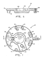
- terminal cluster 34 is mounted within a recess 19 in top cover plate 14′, rather than in central portion 16′.
- a wiring harness including an electrical connector 21 and wiring 23 attaches to the terminal pins of terminal cluster 34 and provides a conductive path for electric current to stator 24 of motor 22.
- Terminal cluster 34 and associated connector 21 are conveniently located within radially extending duct 106, whereby wiring 23 extends through duct 106 and axially extending duct 108 before entering housing chamber 110, where it connects to windings 28 of stator 24.
- the alternative embodiment of Figs. 6 and 7 has special significance to the method of assembling a compressor in accordance with one aspect of the present invention, which will now be described.
- a method of assembling a scroll compressor in accordance with one aspect of the present invention involves top cover plate 14 and the resulting structure described herein.
- cover plate 14 allows compressor mechanism 46 to be completely assembled and attached to cover plate 14 prior to being inserted into the housing interior and the cover plate being attached to the remaining housing shell.
- compressor mechanism 46 is mounted to cover plate 14 as previously described, such that face plate 62 is adjacent cover plate 14.
- compressor mechanism 46 may be already completely assembled, including setting of the air gap between stator 24 and rotor 26.
- a vertically upstanding shell having a top opening wherein the shell comprises central portion 16 and bottom portion 18, as shown in the drawings, or is alternatively of one-piece construction.
- the top cover plate and compressor mechanism assembly is attached to the remainder of the housing such that top cover plate 14 covers the top opening of the housing shell and is sealingly attached thereto, and compressor mechanism 46 extends downwardly into the interior of the housing.
Landscapes
- Engineering & Computer Science (AREA)
- Mechanical Engineering (AREA)
- General Engineering & Computer Science (AREA)
- Rotary Pumps (AREA)
- Applications Or Details Of Rotary Compressors (AREA)
Applications Claiming Priority (2)
| Application Number | Priority Date | Filing Date | Title |
|---|---|---|---|
| US193399 | 1988-05-12 | ||
| US07/193,399 US4911620A (en) | 1988-05-12 | 1988-05-12 | Scroll compressor top cover plate |
Publications (2)
| Publication Number | Publication Date |
|---|---|
| EP0341407A2 true EP0341407A2 (de) | 1989-11-15 |
| EP0341407A3 EP0341407A3 (de) | 1990-07-18 |
Family
ID=22713484
Family Applications (1)
| Application Number | Title | Priority Date | Filing Date |
|---|---|---|---|
| EP89105363A Withdrawn EP0341407A3 (de) | 1988-05-12 | 1989-03-25 | Abdeckplatte für Spiralverdichter |
Country Status (5)
| Country | Link |
|---|---|
| US (1) | US4911620A (de) |
| EP (1) | EP0341407A3 (de) |
| JP (1) | JPH0249986A (de) |
| AU (1) | AU612304B2 (de) |
| BR (1) | BR8902070A (de) |
Cited By (4)
| Publication number | Priority date | Publication date | Assignee | Title |
|---|---|---|---|---|
| GB2406616A (en) * | 2003-10-02 | 2005-04-06 | Scroll Tech | Scroll pump provided with precision holes in fixed scroll and crankcase to assist alignment |
| WO2014141297A3 (en) * | 2013-03-13 | 2015-02-26 | Emerson Climate Technologies, Inc. | Lower bearing assembly for scroll compressor |
| EP2112749A3 (de) * | 2008-04-25 | 2015-04-15 | Kabushiki Kaisha Toyota Jidoshokki | Motorbetriebener Verdichter |
| CN111868384A (zh) * | 2018-09-18 | 2020-10-30 | 富士电机株式会社 | 多级压缩机 |
Families Citing this family (19)
| Publication number | Priority date | Publication date | Assignee | Title |
|---|---|---|---|---|
| US5407335A (en) * | 1986-08-22 | 1995-04-18 | Copeland Corporation | Non-orbiting scroll mounting arrangements for a scroll machine |
| US4875840A (en) * | 1988-05-12 | 1989-10-24 | Tecumseh Products Company | Compressor lubrication system with vent |
| US5040952A (en) * | 1989-02-28 | 1991-08-20 | Kabushiki Kaisha Toshiba | Scroll-type compressor |
| US5176506A (en) * | 1990-07-31 | 1993-01-05 | Copeland Corporation | Vented compressor lubrication system |
| US5290160A (en) * | 1990-09-03 | 1994-03-01 | Mitsubishi Jukogyo Kabushiki Kaisha | Scroll type fluid machinery and assembling method of the same |
| US5180295A (en) * | 1992-01-24 | 1993-01-19 | General Motors Corporation | Scroll compressor Oldham coupling having anti-friction means |
| JPH08159055A (ja) * | 1994-12-08 | 1996-06-18 | Sanden Corp | 高圧タイプ圧縮機 |
| US5683236A (en) * | 1996-03-21 | 1997-11-04 | Alliance Compressors | Anti-reverse rotation valve for scroll compressor |
| KR100480086B1 (ko) * | 1998-01-12 | 2005-06-08 | 엘지전자 주식회사 | 리니어 압축기의 흡입손실 저감구조 |
| US5989608A (en) * | 1998-07-15 | 1999-11-23 | Mizuno; Maki | Food container for cooking with microwave oven |
| US6315528B1 (en) * | 1999-05-27 | 2001-11-13 | Scroll Technologies | Terminal connection in small area of scroll compressor and method for carrying out same |
| US6220839B1 (en) | 1999-07-07 | 2001-04-24 | Copeland Corporation | Scroll compressor discharge muffler |
| US6499977B2 (en) * | 2000-04-24 | 2002-12-31 | Scroll Technologies | Scroll compressor with integral outer housing and a fixed scroll member |
| KR100498376B1 (ko) * | 2002-11-19 | 2005-07-01 | 엘지전자 주식회사 | 스크롤 압축기 및 스크롤 압축기 제조방법 |
| US7070401B2 (en) * | 2004-03-15 | 2006-07-04 | Copeland Corporation | Scroll machine with stepped sleeve guide |
| JP2005337189A (ja) * | 2004-05-31 | 2005-12-08 | Anest Iwata Corp | スクロール流体機械における旋回スクロールの製造方法 |
| KR100559083B1 (ko) * | 2004-12-07 | 2006-03-13 | 삼성광주전자 주식회사 | 압축기의 프레임 및 그 제조방법 |
| US7914268B2 (en) * | 2007-09-11 | 2011-03-29 | Emerson Climate Technologies, Inc. | Compressor having shell with alignment features |
| WO2010013351A1 (ja) * | 2008-07-28 | 2010-02-04 | 株式会社リッチストーン | スクロール流体機械 |
Family Cites Families (17)
| Publication number | Priority date | Publication date | Assignee | Title |
|---|---|---|---|---|
| US19893A (en) * | 1858-04-06 | Of same place | ||
| USRE19893E (en) | 1936-03-17 | Magnetic un loader | ||
| US2130349A (en) * | 1932-09-30 | 1938-09-20 | Gen Motors Corp | Motor-compressor unit for refrigeration |
| US1967035A (en) * | 1933-05-08 | 1934-07-17 | Lipman Patents Corp | Motor compressor unit |
| US2517145A (en) * | 1949-01-08 | 1950-08-01 | Joseph Schilling | Sealed unitary compressor |
| US2612311A (en) * | 1949-01-26 | 1952-09-30 | Borg Warner | Compressor-motor assembly |
| US2670894A (en) * | 1950-10-20 | 1954-03-02 | Borg Warner | Compressor |
| US3924977A (en) * | 1973-06-11 | 1975-12-09 | Little Inc A | Positive fluid displacement apparatus |
| JPS5855359B2 (ja) * | 1980-05-07 | 1983-12-09 | サンデン株式会社 | スクロ−ル型圧縮機 |
| US4609334A (en) * | 1982-12-23 | 1986-09-02 | Copeland Corporation | Scroll-type machine with rotation controlling means and specific wrap shape |
| JPS6073080A (ja) * | 1983-09-30 | 1985-04-25 | Toshiba Corp | スクロ−ル型圧縮装置 |
| JPS60101296A (ja) * | 1983-10-21 | 1985-06-05 | Hitachi Ltd | スクロール圧縮機 |
| JPS60224990A (ja) * | 1984-04-24 | 1985-11-09 | Daikin Ind Ltd | スクロ−ル形圧縮機 |
| JPS6128782A (ja) * | 1984-07-20 | 1986-02-08 | Toshiba Corp | スクロ−ルコンプレツサ |
| JPS61169691A (ja) * | 1985-01-23 | 1986-07-31 | Hitachi Ltd | 冷凍装置用密閉形スクロ−ル圧縮機 |
| JPS6248988A (ja) * | 1985-08-16 | 1987-03-03 | Hitachi Ltd | 密閉形スクロ−ル圧縮機 |
| US4767293A (en) * | 1986-08-22 | 1988-08-30 | Copeland Corporation | Scroll-type machine with axially compliant mounting |
-
1988
- 1988-05-12 US US07/193,399 patent/US4911620A/en not_active Expired - Fee Related
-
1989
- 1989-03-25 EP EP89105363A patent/EP0341407A3/de not_active Withdrawn
- 1989-05-03 BR BR898902070A patent/BR8902070A/pt unknown
- 1989-05-11 AU AU34667/89A patent/AU612304B2/en not_active Ceased
- 1989-05-12 JP JP1117627A patent/JPH0249986A/ja active Pending
Cited By (9)
| Publication number | Priority date | Publication date | Assignee | Title |
|---|---|---|---|---|
| GB2406616A (en) * | 2003-10-02 | 2005-04-06 | Scroll Tech | Scroll pump provided with precision holes in fixed scroll and crankcase to assist alignment |
| US7043817B2 (en) | 2003-10-02 | 2006-05-16 | Scroll Technologies | Method of aligning scroll compressor pump cartridge |
| GB2406616B (en) * | 2003-10-02 | 2006-10-11 | Scroll Tech | Method of aligning scroll compressor pump cartridge |
| EP2112749A3 (de) * | 2008-04-25 | 2015-04-15 | Kabushiki Kaisha Toyota Jidoshokki | Motorbetriebener Verdichter |
| WO2014141297A3 (en) * | 2013-03-13 | 2015-02-26 | Emerson Climate Technologies, Inc. | Lower bearing assembly for scroll compressor |
| CN104704241A (zh) * | 2013-03-13 | 2015-06-10 | 艾默生环境优化技术有限公司 | 用于涡旋式压缩机的下侧轴承组件 |
| US9528517B2 (en) | 2013-03-13 | 2016-12-27 | Emerson Climate Technologies, Inc. | Alignment feature for a lower bearing assembly for a scroll compressor |
| CN111868384A (zh) * | 2018-09-18 | 2020-10-30 | 富士电机株式会社 | 多级压缩机 |
| CN111868384B (zh) * | 2018-09-18 | 2022-06-03 | 富士电机株式会社 | 多级压缩机 |
Also Published As
| Publication number | Publication date |
|---|---|
| AU612304B2 (en) | 1991-07-04 |
| EP0341407A3 (de) | 1990-07-18 |
| US4911620A (en) | 1990-03-27 |
| AU3466789A (en) | 1989-11-16 |
| BR8902070A (pt) | 1989-12-05 |
| JPH0249986A (ja) | 1990-02-20 |
Similar Documents
| Publication | Publication Date | Title |
|---|---|---|
| US4911620A (en) | Scroll compressor top cover plate | |
| US5088906A (en) | Axially floating scroll member assembly | |
| EP0168561B1 (de) | Verdichter mit spiralförmigen Arbeitselementen | |
| US4997349A (en) | Lubrication system for the crank mechanism of a scroll compressor | |
| KR100753647B1 (ko) | 스크롤 압축기 배출머플러 | |
| US4340339A (en) | Scroll type compressor with oil passageways through the housing | |
| US5873710A (en) | Motor spacer for hermetic motor-compressor | |
| US8147229B2 (en) | Motor-compressor unit mounting arrangement for compressors | |
| US4875840A (en) | Compressor lubrication system with vent | |
| US5044904A (en) | Multi-piece scroll members utilizing interconnecting pins and method of making same | |
| US4696629A (en) | Hermetic scroll compressor with welded casing section | |
| US4734020A (en) | Scroll type compressor with spiral oil feeding grooves in thrust bearing | |
| GB2194290A (en) | Electrically driven compressor | |
| AU606566B2 (en) | Scroll compressor with orbiting scroll member biased by oil pressure | |
| US4877381A (en) | Compressor shaft collar through port for pressure equalization between fluid pockets | |
| US5106279A (en) | Orbiting scroll member assembly | |
| AU642623B2 (en) | Scroll compressor including compliance mechanism for the orbiting scroll member | |
| US4934905A (en) | Oil turbulence minimizer for a hermetic compressor | |
| US5013225A (en) | Lubrication system for a scroll compressor | |
| CA2113043C (en) | Scroll compressor unloader valve | |
| JP3550940B2 (ja) | 流体機械 | |
| CA1305688C (en) | Scroll type compressor | |
| JP3124437B2 (ja) | スクロール圧縮機 | |
| JP2671875B2 (ja) | 電動圧縮機 | |
| JPH01237375A (ja) | スクロール圧縮機 |
Legal Events
| Date | Code | Title | Description |
|---|---|---|---|
| PUAI | Public reference made under article 153(3) epc to a published international application that has entered the european phase |
Free format text: ORIGINAL CODE: 0009012 |
|
| AK | Designated contracting states |
Kind code of ref document: A2 Designated state(s): DE FR GB IT |
|
| PUAL | Search report despatched |
Free format text: ORIGINAL CODE: 0009013 |
|
| AK | Designated contracting states |
Kind code of ref document: A3 Designated state(s): DE FR GB IT |
|
| 17P | Request for examination filed |
Effective date: 19900807 |
|
| 17Q | First examination report despatched |
Effective date: 19910523 |
|
| STAA | Information on the status of an ep patent application or granted ep patent |
Free format text: STATUS: THE APPLICATION IS DEEMED TO BE WITHDRAWN |
|
| 18D | Application deemed to be withdrawn |
Effective date: 19921116 |