EP2312916A2 - Leiterplatte und Halbleitermodul - Google Patents
Leiterplatte und Halbleitermodul Download PDFInfo
- Publication number
- EP2312916A2 EP2312916A2 EP10186521A EP10186521A EP2312916A2 EP 2312916 A2 EP2312916 A2 EP 2312916A2 EP 10186521 A EP10186521 A EP 10186521A EP 10186521 A EP10186521 A EP 10186521A EP 2312916 A2 EP2312916 A2 EP 2312916A2
- Authority
- EP
- European Patent Office
- Prior art keywords
- conductive post
- metal plate
- conductive
- circuit board
- semiconductor device
- Prior art date
- Legal status (The legal status is an assumption and is not a legal conclusion. Google has not performed a legal analysis and makes no representation as to the accuracy of the status listed.)
- Granted
Links
- 239000004065 semiconductor Substances 0.000 title claims abstract description 86
- 229910052751 metal Inorganic materials 0.000 claims abstract description 164
- 239000002184 metal Substances 0.000 claims abstract description 164
- 239000011347 resin Substances 0.000 claims description 71
- 229920005989 resin Polymers 0.000 claims description 71
- 238000004873 anchoring Methods 0.000 claims description 32
- 229910000679 solder Inorganic materials 0.000 claims description 30
- 230000003014 reinforcing effect Effects 0.000 claims description 27
- 239000000463 material Substances 0.000 claims description 20
- 238000000034 method Methods 0.000 description 64
- 239000000758 substrate Substances 0.000 description 22
- 239000010949 copper Substances 0.000 description 14
- 125000006850 spacer group Chemical group 0.000 description 13
- RYGMFSIKBFXOCR-UHFFFAOYSA-N Copper Chemical compound [Cu] RYGMFSIKBFXOCR-UHFFFAOYSA-N 0.000 description 9
- 229910052802 copper Inorganic materials 0.000 description 9
- 238000005530 etching Methods 0.000 description 7
- 229910045601 alloy Inorganic materials 0.000 description 6
- 239000000956 alloy Substances 0.000 description 6
- 239000000919 ceramic Substances 0.000 description 4
- 239000004020 conductor Substances 0.000 description 4
- 230000000694 effects Effects 0.000 description 4
- 238000004519 manufacturing process Methods 0.000 description 4
- 230000005855 radiation Effects 0.000 description 4
- 238000000926 separation method Methods 0.000 description 4
- JYEUMXHLPRZUAT-UHFFFAOYSA-N 1,2,3-triazine Chemical compound C1=CN=NN=C1 JYEUMXHLPRZUAT-UHFFFAOYSA-N 0.000 description 3
- XQUPVDVFXZDTLT-UHFFFAOYSA-N 1-[4-[[4-(2,5-dioxopyrrol-1-yl)phenyl]methyl]phenyl]pyrrole-2,5-dione Chemical compound O=C1C=CC(=O)N1C(C=C1)=CC=C1CC1=CC=C(N2C(C=CC2=O)=O)C=C1 XQUPVDVFXZDTLT-UHFFFAOYSA-N 0.000 description 3
- 229910016338 Bi—Sn Inorganic materials 0.000 description 3
- 239000004952 Polyamide Substances 0.000 description 3
- XUIMIQQOPSSXEZ-UHFFFAOYSA-N Silicon Chemical compound [Si] XUIMIQQOPSSXEZ-UHFFFAOYSA-N 0.000 description 3
- 229910020816 Sn Pb Inorganic materials 0.000 description 3
- 229910020888 Sn-Cu Inorganic materials 0.000 description 3
- 229910020922 Sn-Pb Inorganic materials 0.000 description 3
- 229910020994 Sn-Zn Inorganic materials 0.000 description 3
- 229910019204 Sn—Cu Inorganic materials 0.000 description 3
- 229910008783 Sn—Pb Inorganic materials 0.000 description 3
- 229910009069 Sn—Zn Inorganic materials 0.000 description 3
- 229910007570 Zn-Al Inorganic materials 0.000 description 3
- 239000003822 epoxy resin Substances 0.000 description 3
- 238000003780 insertion Methods 0.000 description 3
- 230000037431 insertion Effects 0.000 description 3
- 230000007774 longterm Effects 0.000 description 3
- 239000005011 phenolic resin Substances 0.000 description 3
- 229920003192 poly(bis maleimide) Polymers 0.000 description 3
- 229920002647 polyamide Polymers 0.000 description 3
- 229920000647 polyepoxide Polymers 0.000 description 3
- 229920001721 polyimide Polymers 0.000 description 3
- 239000009719 polyimide resin Substances 0.000 description 3
- 239000010703 silicon Substances 0.000 description 3
- 229910052710 silicon Inorganic materials 0.000 description 3
- 239000010936 titanium Substances 0.000 description 3
- 229910017813 Cu—Cr Inorganic materials 0.000 description 2
- 229910017827 Cu—Fe Inorganic materials 0.000 description 2
- 229910017876 Cu—Ni—Si Inorganic materials 0.000 description 2
- 239000002253 acid Substances 0.000 description 2
- PNEYBMLMFCGWSK-UHFFFAOYSA-N aluminium oxide Inorganic materials [O-2].[O-2].[O-2].[Al+3].[Al+3] PNEYBMLMFCGWSK-UHFFFAOYSA-N 0.000 description 2
- 238000013461 design Methods 0.000 description 2
- 239000000446 fuel Substances 0.000 description 2
- 238000012545 processing Methods 0.000 description 2
- 230000035939 shock Effects 0.000 description 2
- 230000000087 stabilizing effect Effects 0.000 description 2
- 229910000838 Al alloy Inorganic materials 0.000 description 1
- 229910021592 Copper(II) chloride Inorganic materials 0.000 description 1
- 229910000881 Cu alloy Inorganic materials 0.000 description 1
- PXGOKWXKJXAPGV-UHFFFAOYSA-N Fluorine Chemical compound FF PXGOKWXKJXAPGV-UHFFFAOYSA-N 0.000 description 1
- GRYLNZFGIOXLOG-UHFFFAOYSA-N Nitric acid Chemical compound O[N+]([O-])=O GRYLNZFGIOXLOG-UHFFFAOYSA-N 0.000 description 1
- 229910052581 Si3N4 Inorganic materials 0.000 description 1
- RTAQQCXQSZGOHL-UHFFFAOYSA-N Titanium Chemical compound [Ti] RTAQQCXQSZGOHL-UHFFFAOYSA-N 0.000 description 1
- 230000002159 abnormal effect Effects 0.000 description 1
- 238000006243 chemical reaction Methods 0.000 description 1
- 239000003795 chemical substances by application Substances 0.000 description 1
- 239000011248 coating agent Substances 0.000 description 1
- 238000000576 coating method Methods 0.000 description 1
- 239000000470 constituent Substances 0.000 description 1
- 229910000365 copper sulfate Inorganic materials 0.000 description 1
- PMHQVHHXPFUNSP-UHFFFAOYSA-M copper(1+);methylsulfanylmethane;bromide Chemical compound Br[Cu].CSC PMHQVHHXPFUNSP-UHFFFAOYSA-M 0.000 description 1
- ORTQZVOHEJQUHG-UHFFFAOYSA-L copper(II) chloride Chemical compound Cl[Cu]Cl ORTQZVOHEJQUHG-UHFFFAOYSA-L 0.000 description 1
- ARUVKPQLZAKDPS-UHFFFAOYSA-L copper(II) sulfate Chemical compound [Cu+2].[O-][S+2]([O-])([O-])[O-] ARUVKPQLZAKDPS-UHFFFAOYSA-L 0.000 description 1
- 239000011162 core material Substances 0.000 description 1
- 229910052593 corundum Inorganic materials 0.000 description 1
- 238000005336 cracking Methods 0.000 description 1
- 238000005520 cutting process Methods 0.000 description 1
- 238000005516 engineering process Methods 0.000 description 1
- 230000005669 field effect Effects 0.000 description 1
- 239000012530 fluid Substances 0.000 description 1
- 229910052731 fluorine Inorganic materials 0.000 description 1
- 239000011737 fluorine Substances 0.000 description 1
- 239000011888 foil Substances 0.000 description 1
- 230000009477 glass transition Effects 0.000 description 1
- 238000010438 heat treatment Methods 0.000 description 1
- 238000007731 hot pressing Methods 0.000 description 1
- 229910010272 inorganic material Inorganic materials 0.000 description 1
- 239000011147 inorganic material Substances 0.000 description 1
- 239000012212 insulator Substances 0.000 description 1
- 239000007769 metal material Substances 0.000 description 1
- 229910044991 metal oxide Inorganic materials 0.000 description 1
- 150000004706 metal oxides Chemical class 0.000 description 1
- 239000000203 mixture Substances 0.000 description 1
- 238000012986 modification Methods 0.000 description 1
- 230000004048 modification Effects 0.000 description 1
- 229910017604 nitric acid Inorganic materials 0.000 description 1
- JVJQPDTXIALXOG-UHFFFAOYSA-N nitryl fluoride Chemical compound [O-][N+](F)=O JVJQPDTXIALXOG-UHFFFAOYSA-N 0.000 description 1
- 238000007747 plating Methods 0.000 description 1
- 238000003825 pressing Methods 0.000 description 1
- 238000007639 printing Methods 0.000 description 1
- 230000000630 rising effect Effects 0.000 description 1
- HQVNEWCFYHHQES-UHFFFAOYSA-N silicon nitride Chemical compound N12[Si]34N5[Si]62N3[Si]51N64 HQVNEWCFYHHQES-UHFFFAOYSA-N 0.000 description 1
- 238000004544 sputter deposition Methods 0.000 description 1
- 229910052719 titanium Inorganic materials 0.000 description 1
- XLYOFNOQVPJJNP-UHFFFAOYSA-N water Substances O XLYOFNOQVPJJNP-UHFFFAOYSA-N 0.000 description 1
- 229910001845 yogo sapphire Inorganic materials 0.000 description 1
Images


Classifications
-
- H—ELECTRICITY
- H05—ELECTRIC TECHNIQUES NOT OTHERWISE PROVIDED FOR
- H05K—PRINTED CIRCUITS; CASINGS OR CONSTRUCTIONAL DETAILS OF ELECTRIC APPARATUS; MANUFACTURE OF ASSEMBLAGES OF ELECTRICAL COMPONENTS
- H05K3/00—Apparatus or processes for manufacturing printed circuits
- H05K3/10—Apparatus or processes for manufacturing printed circuits in which conductive material is applied to the insulating support in such a manner as to form the desired conductive pattern
- H05K3/20—Apparatus or processes for manufacturing printed circuits in which conductive material is applied to the insulating support in such a manner as to form the desired conductive pattern by affixing prefabricated conductor pattern
- H05K3/202—Apparatus or processes for manufacturing printed circuits in which conductive material is applied to the insulating support in such a manner as to form the desired conductive pattern by affixing prefabricated conductor pattern using self-supporting metal foil pattern
-
- H—ELECTRICITY
- H01—ELECTRIC ELEMENTS
- H01L—SEMICONDUCTOR DEVICES NOT COVERED BY CLASS H10
- H01L23/00—Details of semiconductor or other solid state devices
- H01L23/12—Mountings, e.g. non-detachable insulating substrates
- H01L23/14—Mountings, e.g. non-detachable insulating substrates characterised by the material or its electrical properties
- H01L23/142—Metallic substrates having insulating layers
-
- H—ELECTRICITY
- H01—ELECTRIC ELEMENTS
- H01L—SEMICONDUCTOR DEVICES NOT COVERED BY CLASS H10
- H01L23/00—Details of semiconductor or other solid state devices
- H01L23/34—Arrangements for cooling, heating, ventilating or temperature compensation ; Temperature sensing arrangements
- H01L23/36—Selection of materials, or shaping, to facilitate cooling or heating, e.g. heatsinks
- H01L23/373—Cooling facilitated by selection of materials for the device or materials for thermal expansion adaptation, e.g. carbon
- H01L23/3735—Laminates or multilayers, e.g. direct bond copper ceramic substrates
-
- H—ELECTRICITY
- H01—ELECTRIC ELEMENTS
- H01L—SEMICONDUCTOR DEVICES NOT COVERED BY CLASS H10
- H01L23/00—Details of semiconductor or other solid state devices
- H01L23/48—Arrangements for conducting electric current to or from the solid state body in operation, e.g. leads, terminal arrangements ; Selection of materials therefor
- H01L23/488—Arrangements for conducting electric current to or from the solid state body in operation, e.g. leads, terminal arrangements ; Selection of materials therefor consisting of soldered or bonded constructions
- H01L23/498—Leads, i.e. metallisations or lead-frames on insulating substrates, e.g. chip carriers
- H01L23/49811—Additional leads joined to the metallisation on the insulating substrate, e.g. pins, bumps, wires, flat leads
-
- H—ELECTRICITY
- H01—ELECTRIC ELEMENTS
- H01L—SEMICONDUCTOR DEVICES NOT COVERED BY CLASS H10
- H01L23/00—Details of semiconductor or other solid state devices
- H01L23/48—Arrangements for conducting electric current to or from the solid state body in operation, e.g. leads, terminal arrangements ; Selection of materials therefor
- H01L23/488—Arrangements for conducting electric current to or from the solid state body in operation, e.g. leads, terminal arrangements ; Selection of materials therefor consisting of soldered or bonded constructions
- H01L23/498—Leads, i.e. metallisations or lead-frames on insulating substrates, e.g. chip carriers
- H01L23/49833—Leads, i.e. metallisations or lead-frames on insulating substrates, e.g. chip carriers the chip support structure consisting of a plurality of insulating substrates
-
- H—ELECTRICITY
- H01—ELECTRIC ELEMENTS
- H01L—SEMICONDUCTOR DEVICES NOT COVERED BY CLASS H10
- H01L24/00—Arrangements for connecting or disconnecting semiconductor or solid-state bodies; Methods or apparatus related thereto
- H01L24/01—Means for bonding being attached to, or being formed on, the surface to be connected, e.g. chip-to-package, die-attach, "first-level" interconnects; Manufacturing methods related thereto
- H01L24/18—High density interconnect [HDI] connectors; Manufacturing methods related thereto
-
- H—ELECTRICITY
- H01—ELECTRIC ELEMENTS
- H01L—SEMICONDUCTOR DEVICES NOT COVERED BY CLASS H10
- H01L25/00—Assemblies consisting of a plurality of individual semiconductor or other solid state devices ; Multistep manufacturing processes thereof
- H01L25/03—Assemblies consisting of a plurality of individual semiconductor or other solid state devices ; Multistep manufacturing processes thereof all the devices being of a type provided for in the same subgroup of groups H01L27/00 - H01L33/00, or in a single subclass of H10K, H10N, e.g. assemblies of rectifier diodes
- H01L25/04—Assemblies consisting of a plurality of individual semiconductor or other solid state devices ; Multistep manufacturing processes thereof all the devices being of a type provided for in the same subgroup of groups H01L27/00 - H01L33/00, or in a single subclass of H10K, H10N, e.g. assemblies of rectifier diodes the devices not having separate containers
- H01L25/07—Assemblies consisting of a plurality of individual semiconductor or other solid state devices ; Multistep manufacturing processes thereof all the devices being of a type provided for in the same subgroup of groups H01L27/00 - H01L33/00, or in a single subclass of H10K, H10N, e.g. assemblies of rectifier diodes the devices not having separate containers the devices being of a type provided for in group H01L29/00
- H01L25/072—Assemblies consisting of a plurality of individual semiconductor or other solid state devices ; Multistep manufacturing processes thereof all the devices being of a type provided for in the same subgroup of groups H01L27/00 - H01L33/00, or in a single subclass of H10K, H10N, e.g. assemblies of rectifier diodes the devices not having separate containers the devices being of a type provided for in group H01L29/00 the devices being arranged next to each other
-
- H—ELECTRICITY
- H01—ELECTRIC ELEMENTS
- H01L—SEMICONDUCTOR DEVICES NOT COVERED BY CLASS H10
- H01L2924/00—Indexing scheme for arrangements or methods for connecting or disconnecting semiconductor or solid-state bodies as covered by H01L24/00
- H01L2924/10—Details of semiconductor or other solid state devices to be connected
- H01L2924/11—Device type
- H01L2924/12—Passive devices, e.g. 2 terminal devices
- H01L2924/1204—Optical Diode
- H01L2924/12042—LASER
-
- H—ELECTRICITY
- H01—ELECTRIC ELEMENTS
- H01L—SEMICONDUCTOR DEVICES NOT COVERED BY CLASS H10
- H01L2924/00—Indexing scheme for arrangements or methods for connecting or disconnecting semiconductor or solid-state bodies as covered by H01L24/00
- H01L2924/10—Details of semiconductor or other solid state devices to be connected
- H01L2924/11—Device type
- H01L2924/13—Discrete devices, e.g. 3 terminal devices
- H01L2924/1301—Thyristor
-
- H—ELECTRICITY
- H01—ELECTRIC ELEMENTS
- H01L—SEMICONDUCTOR DEVICES NOT COVERED BY CLASS H10
- H01L2924/00—Indexing scheme for arrangements or methods for connecting or disconnecting semiconductor or solid-state bodies as covered by H01L24/00
- H01L2924/10—Details of semiconductor or other solid state devices to be connected
- H01L2924/11—Device type
- H01L2924/13—Discrete devices, e.g. 3 terminal devices
- H01L2924/1304—Transistor
- H01L2924/1305—Bipolar Junction Transistor [BJT]
- H01L2924/13055—Insulated gate bipolar transistor [IGBT]
-
- H—ELECTRICITY
- H01—ELECTRIC ELEMENTS
- H01L—SEMICONDUCTOR DEVICES NOT COVERED BY CLASS H10
- H01L2924/00—Indexing scheme for arrangements or methods for connecting or disconnecting semiconductor or solid-state bodies as covered by H01L24/00
- H01L2924/10—Details of semiconductor or other solid state devices to be connected
- H01L2924/11—Device type
- H01L2924/13—Discrete devices, e.g. 3 terminal devices
- H01L2924/1304—Transistor
- H01L2924/1306—Field-effect transistor [FET]
- H01L2924/13091—Metal-Oxide-Semiconductor Field-Effect Transistor [MOSFET]
-
- H—ELECTRICITY
- H05—ELECTRIC TECHNIQUES NOT OTHERWISE PROVIDED FOR
- H05K—PRINTED CIRCUITS; CASINGS OR CONSTRUCTIONAL DETAILS OF ELECTRIC APPARATUS; MANUFACTURE OF ASSEMBLAGES OF ELECTRICAL COMPONENTS
- H05K2201/00—Indexing scheme relating to printed circuits covered by H05K1/00
- H05K2201/03—Conductive materials
- H05K2201/0332—Structure of the conductor
- H05K2201/0388—Other aspects of conductors
- H05K2201/0397—Tab
-
- H—ELECTRICITY
- H05—ELECTRIC TECHNIQUES NOT OTHERWISE PROVIDED FOR
- H05K—PRINTED CIRCUITS; CASINGS OR CONSTRUCTIONAL DETAILS OF ELECTRIC APPARATUS; MANUFACTURE OF ASSEMBLAGES OF ELECTRICAL COMPONENTS
- H05K2201/00—Indexing scheme relating to printed circuits covered by H05K1/00
- H05K2201/09—Shape and layout
- H05K2201/09009—Substrate related
- H05K2201/09118—Moulded substrate
-
- H—ELECTRICITY
- H05—ELECTRIC TECHNIQUES NOT OTHERWISE PROVIDED FOR
- H05K—PRINTED CIRCUITS; CASINGS OR CONSTRUCTIONAL DETAILS OF ELECTRIC APPARATUS; MANUFACTURE OF ASSEMBLAGES OF ELECTRICAL COMPONENTS
- H05K2201/00—Indexing scheme relating to printed circuits covered by H05K1/00
- H05K2201/09—Shape and layout
- H05K2201/09209—Shape and layout details of conductors
- H05K2201/09654—Shape and layout details of conductors covering at least two types of conductors provided for in H05K2201/09218 - H05K2201/095
- H05K2201/0969—Apertured conductors
-
- H—ELECTRICITY
- H05—ELECTRIC TECHNIQUES NOT OTHERWISE PROVIDED FOR
- H05K—PRINTED CIRCUITS; CASINGS OR CONSTRUCTIONAL DETAILS OF ELECTRIC APPARATUS; MANUFACTURE OF ASSEMBLAGES OF ELECTRICAL COMPONENTS
- H05K2201/00—Indexing scheme relating to printed circuits covered by H05K1/00
- H05K2201/10—Details of components or other objects attached to or integrated in a printed circuit board
- H05K2201/10007—Types of components
- H05K2201/10166—Transistor
-
- H—ELECTRICITY
- H05—ELECTRIC TECHNIQUES NOT OTHERWISE PROVIDED FOR
- H05K—PRINTED CIRCUITS; CASINGS OR CONSTRUCTIONAL DETAILS OF ELECTRIC APPARATUS; MANUFACTURE OF ASSEMBLAGES OF ELECTRICAL COMPONENTS
- H05K2201/00—Indexing scheme relating to printed circuits covered by H05K1/00
- H05K2201/10—Details of components or other objects attached to or integrated in a printed circuit board
- H05K2201/10227—Other objects, e.g. metallic pieces
- H05K2201/10295—Metallic connector elements partly mounted in a hole of the PCB
- H05K2201/10303—Pin-in-hole mounted pins
-
- H—ELECTRICITY
- H05—ELECTRIC TECHNIQUES NOT OTHERWISE PROVIDED FOR
- H05K—PRINTED CIRCUITS; CASINGS OR CONSTRUCTIONAL DETAILS OF ELECTRIC APPARATUS; MANUFACTURE OF ASSEMBLAGES OF ELECTRICAL COMPONENTS
- H05K3/00—Apparatus or processes for manufacturing printed circuits
- H05K3/22—Secondary treatment of printed circuits
- H05K3/28—Applying non-metallic protective coatings
Definitions
- This application relates generally to a circuit board and a semiconductor module, and more particularly to a circuit board and a semiconductor module for mounting switching devices used particularly in automotive electrical equipment, information equipment and electrical equipment, and power semiconductor devices such as power MOSFET (Metal Oxide Semiconductor Field Effect Transistors), GTO (Gate Turn Off Thyristors), power transistors, IGBT (Insulated Gate Bipolar Transistors) devices and the like.
- power MOSFET Metal Oxide Semiconductor Field Effect Transistors
- GTO Gate Turn Off Thyristors
- IGBT Insulated Gate Bipolar Transistors
- IGBT insulated-gate bipolar transistors
- other semiconductor devices used in high-current, high-voltage operating environments, durability against repeated heat cycles and high heat radiation properties are necessary in addition to maintaining component stability.
- a semiconductor module that has a conductive post to enhance heat radiation.
- This semiconductor module has an insulated substrate (support substrate) having a plurality of through holes, conductive posts (copper pins) positioned on the through holes of the insulated substrate and a semiconductor device mounted on the insulator substrate. Furthermore, the conductive posts and the electrodes of the semiconductor device are electrically connected.
- Patent Literature 1 Unexamined Japanese Patent Application KOKAI Publication No. 2006-237429
- the circuit board according to the present invention is a circuit board (10) for mounting a semiconductor device (50) having at least a first electrode (51), a second electrode (52) and a third electrode (53), and has a first conductive post (31) for electrically connecting to the first electrode (51) of the semiconductor device (50), a first metal (11) plate connecting to the first conductive post (31) , a second conductive post (32) for electrically connecting to the second electrode (52) of the semiconductor device (50), a second metal plate (12) connecting to the second conductive post (32), a third conductive post (33) for electrically connecting to the third electrode (53) of the semiconductor device (50) and a third metal plate (13) connecting to the third conductive post (33).
- the semiconductor module (1000) has the above-described circuit board (10) and a semiconductor device (50) having at least a first electrode (51), a second electrode (52) and a third electrode (53), characterized in that at least one out of the first through third metal plates (11 to 13) is positioned so as to face the semiconductor device (50) and is electrically connected to the semiconductor device (50) via at least one of the first through third conductive posts (31 to 33).
- the circuit board is composed of conductive posts and metal plates, so heat generated from the semiconductor device can be efficiently dispersed. Moreover, because the structural components are made of metal materials, a circuit board and a semiconductor module that can withstand shocks and vibrations and have high long-term reliability can be provided.
- FIG. 1A shows a semiconductor module 1000 according to the present embodiment.
- a second metal plate 12 is depicted by dashed lines and shown transparent in order to make it easier to see the connection area between a circuit board 10 and a semiconductor device 50.
- FIG. 1B is a cross-sectional view along line X-X' in FIG. 1A
- FIG. 1C is a cross-sectional view along line Y1-Y1' in FIG. 1A
- FIG. 1D is a cross-sectional view along line Y2-Y2' in FIG. 1A .
- FIG. 1E shows the connection part of conductive posts 31 to 33 by arrows, with the circuit board 10 separated from the semiconductor module 1000.
- the semiconductor module 1000 of the present embodiment is provided with a circuit board 10, a semiconductor device 50 and a heat sink 100.
- the semiconductor module 1000 is mounted, for example, in an HV (hybrid vehicle) such as a FCHEV (fuel cell hybrid electric vehicle), and is used for example to boost the voltage from the battery or as a switching device for motor control.
- HV hybrid vehicle
- FCHEV fuel cell hybrid electric vehicle
- applications of the semiconductor module 1000 are not limited to this.
- the semiconductor device 50 is, for example, a square plate IGBT device, a GTO thyristor device or the like. It is possible to utilize a similar structure with a semiconductor device having two electrodes, such as a free wheeling diode (FWD) or the like.
- FWD free wheeling diode
- a heat sink 100 is provided on the bottom surface of the semiconductor device 50. Through this, heat-radiating properties are enhanced, the rising temperature of the semiconductor device 50 can be reduced and damage and abnormal operations can be prevented.
- the circuit board 10 is electrically connected to the top surface of the semiconductor device 50
- the circuit board 10 has a first metal plate 11, a second metal plate 12, a third metal plate 13, insulating anchoring resin 21, reinforcing resin 22, a first conductive post 31, a second conductive post 32 and a third conductive post 33.
- at least one of the first through third metal plates 11 to 13 is positioned facing the semiconductor device 50, and is preferably connected electrically to the semiconductor device 50 via at least one of the first through third conductive posts 31 to 33.
- each of the first through third metal plates 11 to 13 is positioned facing the semiconductor device 50, and the circuit board 10 is electrically connected to the semiconductor device 50 via any of the first through third conductive posts 31 to 33.
- the material of the first through third metal plates 11 to 13 is preferably a conductive material with high thermal transmittivity and high heat capacity.
- the first through third metal plates 11 to 13 are preferably made of Cu, a Cu-Cr alloy, a Cu-Ni-Si alloy or a Cu-Fe alloy, and more preferably made from Cu.
- the first through third metal plates 11 to 13 may be connected to any of the electrodes, but it is preferable for the second metal plate 12 to connect to a control electrode (for example a gate electrode 52 ) of the semiconductor device 50.
- the second metal plate 12 preferably has more conductivity and flexibility than the other metal plates (the first and third metal plates 11 and 13 ), and for example is preferably a metal foil or a flexible wiring board.
- the materials of the first through third metal plates 11 to 13 are not limited to these materials. It is possible to enhance mounting compatibility with the control board and freedom in design if at least one out of the first through third metal plates 11 to 13 has greater flexibility than the other metal plates.
- the first and third metal plates 11 and 13 are each composed of copper plates for example around 1.0 mm thick. Because extremely large electric currents flow in HV (hybrid vehicles) such as FCHEV (fuel cell hybrid electric vehicles), it is desirable to enlarge the heat capacity in order to discharge heat.
- HV hybrid vehicles
- FCHEV fuel cell hybrid electric vehicles
- the second metal plate 12 is composed of a copper plate for example around 0.2 mm thick. This makes it possible to endow the second metal plate 12 with flexibility and also improves mounting.
- the anchoring resin 21 and the reinforcing resin 22 are used to anchor the first through third metal plates 11 to 13, for example, as shown in FIGS. 1B to 1D .
- the anchoring resin 21 is positioned between the first conductive post 31 and the second conductive post 32, between the second conductive post 32 and the third conductive post 33 and between the third conductive post 33 and the first conductive post 31, mechanically connecting and electrically insulating the first through third metal plates 11 to 13.
- the reinforcing resin 22 covers the first through third metal plates 11 to 13 and the anchoring resin 21.
- the anchoring resin 21 is considered to have achieved the effect of stabilizing the first through third metal plates 11 to 13 if the anchoring resin 21 is in at least one out of between the first conductive post 31 and the second conductive post 32 , between the second conductive post 32 and the third conductive post 33 and between the third conductive post 33 and the first conductive post 31 and mechanically connects and electrically insulates at least two of the first through third metal plates 11 to 13.
- the reinforcing resin 22 is considered to achieve the effect of further stabilizing the first through third metal plates 11 to 13 and other components if the reinforcing resin 22 covers the anchoring resin 21 and at least one out of the first through third metal plates 11 to 13.
- the anchoring resin 21 and the reinforcing resin 22 are composed of bismaleimide triazine resin (BT resin).
- BT resin bismaleimide triazine resin
- materials for the anchoring resin 21 or the reinforcing resin 22 epoxy resin, phenol resin, polyimide resin, polyamide, silicon resin and the like may be cited, for example.
- the anchoring resin 21 is preferably bismaleimide triazine resin, epoxy resin, phenol resin, polyimide resin, polyamide or silicon resin.
- the reinforcing resin 22 is preferably bismaleimide triazine resin, epoxy resin, phenol resin, polyimide resin, polyamide or silicon resin.
- the anchoring resin 21 and the reinforcing resin 22 are formed as necessary, and the shapes and materials thereof may be changed in accordance with application.
- Holes 31a, 32a and 33a are formed in the anchoring resin 21 and the first through third metal plates 11 to 13 in order to insert (for example, fit) the first through third conductive posts 31 to 33 in predetermined positions.
- the holes 31a, 32a and 33a are, for example, through holes or holes with bottoms.
- the first through third conductive posts 31 to 33 are connected to the first through third metal plates 11 to 13, respectively, and furthermore are electrically connected to a collector electrode 51 (first electrode), gate electrode 52 (second electrode) and emitter electrode 53 (third electrode) of the semiconductor device 50.
- the first, second and third conductive posts 31, 32 and 33 are inserted into the holes 31a, 32a and 33a, respectively.
- solder 25 is positioned on one end of the first through third conductive posts 31 to 33. This solder 25 is also poured into contact parts with the first through third conductive posts 31 to 33 and the first through third metal plates 11 to 13 (see FIG. 2D ).
- the first through third metal plates 11 to 13 and one end of the first through third conductive posts 31 to 33 are electrically connected via the solder 25, as shown in FIGS. 1B to 1D .
- the connection between the second conductive post 32 and the second metal plate 12 and the connection between the third conducive post 33 and the third metal plate 13 are connected by solder.
- the first through third conductive posts 31 to 33 are preferably each fitted into the first through third metal plates 11 to 13.
- the reinforcing resin 22 preferably covers the insertion holes of the first through third conductive posts 31 to 33. This makes it possible to prevent the solder 25 from peeling off and to preserve connection reliability.
- the materials for the first through third conductive posts 31 to 33 are arbitrary, but the first through third conductive posts 31 to 33 are preferably composed of Cu, a Cu-Cr alloy, a Cu-Ni-Si alloy, a Cu-Fe alloy, Al or an Al alloy, and more preferably Cu.
- at least one pair out of the first metal plate 11 and the first conductive post 31, the second metal plate 12 and the second conductive post 32, the third metal plate 13 and the third conductive post 33 are preferably composed of substantially similar materials. Through this, connection strength, electrical properties and the like are improved.
- solder 25 is arbitrary, but the solder 25 is preferably an Sn-Cu type, a Bi-Sn type, an Sn-Pb type, a Zn-Al type or an Sn-Zn type.
- the semiconductor device 50 has a collector electrode 51, a gate electrode 52 and an emitter electrode 53.
- the semiconductor device 50 and a spacer 54 are mounted on a metal layer 104 formed on the heat sink 100.
- the material of the spacer 54 is an arbitrary conductor, and for example Cu or a Cu alloy may be used as the material of the spacer 54.
- the spacer 54 may be a metal, such as copper, plated on a core material composed of resin, metal or ceramic.
- the collector electrode 51 is electrically connected to the metal layer 104, and is electrically connected to the first metal plate 11 via the spacer 54 and the first conductive post 31.
- the gate electrode 52 is electrically connected to the second metal plate 12 via the second conductive post 32.
- the emitter electrode 53 is electrically connected to the third metal plate 13 via the third conductive post 33.
- the first through third metal plates 11 to 13 are positioned roughly parallel to the surface of the semiconductor device 50.
- the spacer 54 is provided in accordance with the length of the first conductive post 31, and need not be supplied when not unifying the lengths of the conductive posts.
- the heat sink 100 is composed of a substrate 100a, and a metal layer 104 formed on the top and bottom surfaces of the substrate 100a.
- the metal layer 104 is formed on both surfaces of the heat sink 100, but this is intended to be illustrative and not limiting, for the metal layer 104 may be formed only on the top surface (the surface on the mounting side) of the heat sink 100.
- the material of the substrate 100a is preferably a material that has high heat radiation properties.
- the substrate 100a is composed, for example, of ceramic (for example, aluminum nitride: AlN; silicon nitride: SiN, Alumina: Al 2 O 3 ; Berylia: BeO, or the like).
- the material of the substrate 100a is not limited to inorganic materials such as ceramics and may be resin or metal, for example.
- the metal layer 104 may be omitted.
- the semiconductor device 50 is mounted on the heat sink 100.
- the metal layer 104 is electrically connected to the first metal plate 11 via the first conductive post 31.
- the metal layer 104 on the mounting side is electrically connected to the first metal plate 11.
- this is intended to be illustrative and not limiting, for the metal layer 104 on both sides may be electrically connected to the first metal plate 11.
- FIG. 2A is a cross-sectional view of the first through third conductive posts 31 to 33 and FIG. 2B is a top view of the first through third conductive posts 31 to 33.
- the first through third conductive posts 31 to 33 are provided with a flange 500, a head 501a and a foot 501b.
- the shape of the first through third conductive posts 31 to 33 may be changed as necessary.
- the length of the head 501a and the length of the foot 501b are preferably roughly the same, but this is intended to be illustrative and not limiting.
- a surface 500s of the flange 500 of the first through third conductive posts 31 to 33 and a surface 501s of the head 501a or the foot 501b preferably include uneven surfaces.
- the surface area of the first through third conductive posts 31 to 33 is increased, and as shown in FIG. 2D , when the first through third conductive posts 31 to 33 are inserted into the holes 31a to 33a (through holes) in the first through third metal plates 11 to 13 and the solder 25 is formed, the surface area of contact between the first through third conductive posts 31 to 33 and the first through third metal plates 11 to 13 becomes larger. As a result, it is possible to increase connection reliability.
- a notch 501c is preferably formed on one or both of the head 501a and the foot 501b (each end) of the first through third conductive posts 31 to 33, as shown in FIGS. 2E to 2G . Not only does this increase contact surface area, this is effective in removing air during solder reflow.
- the thickness of the first through third conductive posts 31 to 33 may be changed in accordance with the connecting electrodes.
- the first through third conductive posts 31 to 33 may each have mutually differing thicknesses.
- the diameters of the first conductive post 31 and the third conductive post 33 connected to the collector electrode 51 and the emitter electrode 53, through which large electrical currents flow are preferably smaller than the diameter of the second conductive post 32 connected to the gate electrode 52, through which comparatively small electrical currents flow.
- the cross-sectional area of the first and third conductive posts 31 and 33 as a whole is preferable for the cross-sectional area of the first and third conductive posts 31 and 33 as a whole to be larger than that of the second conductive post 32 connected to the gate electrode 52, such as by increasing the number of these conductive posts. By so doing, it becomes possible to reduce the joule resistance of the first and third conductive posts 31 and 33.
- the directions in which the first through third conductive posts 31 to 33 protrude from the first through third metal plates 11 to 13 are parallel to each other.
- the front edge surfaces of the first through third conductive posts 31 to 33 are preferably parallel to each other.
- the protrusion directions of the first through third conductive posts 31 to 33 are all in the Z direction ( FIG. 1 ), and the front edge surfaces of the first through third conductive posts 31 to 33 are all in the X-Y plane ( FIG. 1 ).
- the first through third metal plates 11 to 13 are connected to the conductor (spacer 54 ) on the surface of the heat sink 100 and the conductors (gate electrode 52 and emitter electrode 53 ) on the surface of the semiconductor device 50 via the first through third conductive posts 31 to 33.
- the first through third metal plates 11 to 13 can on their own secure stability of the components and metal plates themselves.
- the first through third metal plates 11 to 13 unlike resin substrates, are less susceptible to thermal deformation and are less likely to remain deformed. Consequently, even under environments such as automobiles and other transportation equipment in which vibrations and shocks are abundant, it is possible to anticipate the effect of maintaining the stability of components.
- FIG. 3A is a cross-sectional view at the position of the metal plate
- FIG. 3B is a cross-sectional view along line A-A' in FIG. 3A .
- the first through third metal plates 11 to 13 are arranged in predetermined positions on the metal mold jig 1031, and the first through third metal platens 11 to 13 are anchored by the metal mold jib 1032.
- anchoring resin 21 is poured from a pouring mouth (unrepresented) provided in the metal mold jig 1031 or 1032. Furthermore, after heating and solidifying, the metal mold jigs 1031 and 1032 are removed.
- holes 31a, 32a and 33a are bored in order to insert the first through third conductive posts 31 to 33 in predetermined positions.
- the first through third conductive posts 31 to 33 are fitted into the first through third metal plates 11 to 13 using a first jig 1011 and a second jig 1012.
- the first jig 1011 and the second jig 1012 are prepared.
- the first jig 1011 has holes 1011a with diameters the same as or slightly larger than the shaft diameters of the first through third conductive posts 31 to 33.
- the holes 1011a are formed in correspondence with the positions into which the first through third conductive posts 31 to 33 are fitted.
- the second jig 1021 is a jig for housing the flanges 500 ( FIG. 2A ) of the first through third conductive posts 31 to 33 in holes 1012a.
- FIG. 3F by causing the first jig 1011 and 1012 to vibrate, the first through third conductive posts 31 to 33 (only the second and third conductive posts 32 and 33 are shown in the drawing) are fitted into the holes 101 1a.
- the first through third metal plates 11 to 13 anchored by the anchoring resin 21 are held down and pressed using a jig 1013, as shown in FIG 3H .
- the first through third conductive posts 31 to 33 are fitted (press fit inserted) into the holes 31a, 32a and 33a (see FIGS. 1B and 1C ) formed in the first through third metal plates 11 to 13.
- the two are interlocked.
- solder balls ball-shaped solder 25 (solder balls) is mounted on the first through third conductive posts 31 to 33 using a solder mask 1014.
- the solder mask it is possible to use a thin material with holes positioned corresponding to the conductive posts.
- the solder ball may be solder of the Sn-Cu type, Bi-Sn type, Sn-Pb type, Zn-Al type, Sn-Zn type or the like formed into a ball, and the size may be selected from several dozen ⁇ m to around 1 mm in accordance with the necessary quantity of solder.
- the solder 25 is melted by reflowing at 200° to 250° C, for example, and flows into the gaps in the holes 31a, 32a and 33a ( FIG. 2D ).
- the first through third metal plates 11 to 13 and the first through third conductive posts 31 to 33 are firmly connected.
- reinforcing resin 22 is formed on the entire surface of the metal plates 11 to 13, including the solder 25. Through this, the circuit board 10 is completed.
- a substrate 100a composed of ceramic is prepared.
- a first groundwork layer 102a composed of titanium (Ti) with a thickness of 0.1 ⁇ m and a second groundwork layer 102b composed of copper with a thickness of 1.0 ⁇ m are formed in that order on both surfaces of the substrate 100a through sputtering for 5 to 15 minutes with 4 to 5 kW DG of an Ar plasma, for example.
- a groundwork layer 102 composed of the first groundwork layer 102a and the second groundwork layer 102b is formed.
- the first and second groundwork layers 102a and 102b are each formed as beta patterns.
- an electroplated film 104c is formed on both surfaces on the groundwork layer 102.
- electrolytic copper plating is accomplished for 30 minutes with an electric current volume of 3A/dm 2 after submersion in a solution of copper sulfate with the substrate 100a as the cathode and a copper plate electrode as the anode, for example.
- an etching resist 1021a is formed at a predetermined position on the electroplated film 104c.
- the etching resist forms a circuit pattern.
- the etching film it is possible to use a printing method in which an acid-resistant ink is screen printed, for example, or a photography method in which the entire surface of the electroplated film 104c is covered by a photosensitive agent and dry film, only the conductive pattern portion is exposed to light, developing and fixing are performed and the acid-resistant coating is left.
- the groundwork layer 102 and the electroplated film 104c exposed from the etching resist 1021a on both sides of the substrate 100a are removed by etching.
- a metal layer 104a and a groundwork layer 103 are formed on both sides of the substrate 100a, and a metal layer 104 composed ofthis metal layer 104a and the groundwork layer 103 is completed.
- the groundwork layer 103 is composed of a first groundwork layer 103a and a second groundwork layer 103b, and is a circuit pattern, not a beta pattern.
- the copper etching fluid it is possible to use a CuCl 2 solution or a fluoro-nitric acid solution (fluorine:nitric acid:water ratio of 1:1:18) for etching Ti. Through the above, the heat sink 100 is completed.
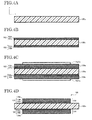
- FIG. 5A corresponding to the cross section in FIG. 1B
- FIG. 5B corresponding to the cross section in FIG. 1C
- the semiconductor device 50 and the spacer 54 mounted on the heat sink 100, and the circuit board 10 are mounted via solders 52a to 54a, and thereby the semiconductor module 1000 according to this embodiment of the present invention is completed.
- solders 52a to 54a ( FIGS. 1B to 1D ). It is possible to form the solders 52a to 54a by immersing the tip of the first through third conductive posts 31 to 33 in a vat in which Sn-Cu type, Bi-Sn type, Sn-Pb type, Zn-Al type or Sn-Zn type solder, for example, has been melted.
- the solder layer may be formed by using solder balls on top of the semiconductor device 50 (gate electrode 52 and emitter electrode 53) and the heat sink 100 (spacer 54).
- the method of producing the present embodiment is applied to production of the semiconductor module 1000. With this kind of production method, a good semiconductor module 1000 can be obtained at low cost.
- a plurality of semiconductor devices may be used.
- a plurality of semiconductor devices of differing types may be used.
- a separate FWD device 60 may be mounted in parallel between the emitter and collector of the IGBT device.
- the top surface of the FWD device 60 is electrically connected to the first through third metal plates 11 to 13 via the first through third conductive posts 31 to 33, the same as the semiconductor device 50.
- the FWD device 60 has an electrode 61 on a first surface and an electrode 62 on a second surface on the side opposite the first surface.
- the FWD device 60 is mounted on the metal layer 104 formed on the heat sink 100.
- the electrode 61 is electrically connected to the third metal plate 13 via the third conductive post 33.
- the electrode 62 is electrically connected to the first metal plate 11 via the metal layer 104 and the first conductive post 31.
- FIGS. 7A to 7G respectively show cross sections corresponding to the cross sections shown in FIG. 1C .
- the holes 31a, 32a and 33a may be holes with bottoms that do not pass through the anchoring resin 21.
- the anchoring resin 21 can fill the role of the reinforcing resin 22, making it possible to reduce the number of processes and also prevent peeling off the solder 25 (see FIGS. 1B and 1C ), thereby preserving connection reliability.
- the holes 31a, 32a and 33a (see FIG. 2D ) formed in the first through third metal plates 11 to 13 for fitting the first through third conductive posts 31 to 33 may be holes with bottoms exposing the first through third metal plates 11 to 13 (only the second and third metal plates 12 and 13 are shown in the drawing). Furthermore, conductive posts 32T and 33T having T-shaped cross-sections may be connected to these holes with bottoms. Through this, it is possible to control tilting of the first through third conductive posts 31 to 33 and to electrically connect to the first through third metal plates 11 to 13 more surely.
- a second metal plate 12b having roughly the same thickness in the part covered by the anchoring resin 21 and the reinforcing resin 22 as the first and third metal plates 11 and 13 may be used in place of the second metal plate 12.
- the first through third conductive posts 31 to 33 are surely formed on a roughly planar surface and furthermore it is possible to enlarge the contact surface area between the second conductive post 32 and the second metal plate 12b. As a result, the connection reliability of the second conductive post 32 is improved.
- the first through third conductive posts 31 to 33 may be formed with the same material as the first through third metal plates 11 to 13 by processing the metal plates.
- the second and third conductive posts 32P and 33P may be formed of the same material and integrally with the second and third metal plates 12c and 13b by processing the second and third metal plates 12c and 13b.
- the thicknesses of the first through third metal plates 11 to 13 may all be the same.
- the second metal plate 12d may be used in place of the second metal plate 12, as shown in FIG. 7E .
- the connection reliability of the second conductive post 32 is improved.
- the thickness of anchoring resin 21 provided on the bottom surface of the second metal plate 12 may be adjusted so as to be roughly the same as the first and third metal plates 11 and 13. That is to say, in this case the anchoring resin 21 is not covered on the first and third metal plates 11 and 13.
- the second metal plate 12 may be connected by the anchoring resin 21, the first through third conductive posts 31 to 33 may be inserted and the upper and lower surfaces covered by the reinforcing resin 22 so as to anchor these.
- the first through third conductive posts 31 to 33 are formed roughly coplanar, and the flanges 500 ( FIG.
- first through third conductive posts 31 to 33 and the various metal plates can be connected with certainty.
- connection reliability of the first through third conductive posts 31 to 33 is improved.
- strength is improved because the reinforcing resin 22 can be formed on the top and bottom surfaces of the third metal plate 13.
- the shapes of the first through third conductive posts 31 to 33 are arbitrary and are not limited to that shown in FIGS. 2A through 2G .
- the shape of the first through third conductive posts 31 to 33 may be a polygonal column.
- the shapes of the first through third conductive posts 31 to 33 may be different from each other. However, manufacturing is made easier by making the first through third conductive posts 31 to 33 have the same shape.
- the first through third conductive posts 31 to 33 have mutually differing shapes
- the first through third conductive posts 31 to 33 are set in the jib using the method shown in FIGS. 8A and 8B , for example.
- the through holes in which the first and second conductive posts 31 and 32 other than the third conductive post 33 are to be inserted are blocked using a second jig 1015, and the third conductive post 33 is set up in the first jig 1011, as shown in FIG. 8A .
- the through hole (not shown) into which the first conductive post 31 is to be inserted is blocked using a third jig 1016, and the second conductive post 32 is set up in the first jig 1011.
- the second and third conductive posts 32 and 33 are inserted into the through holes other than the through hole into which the first conductive post 31 is to be inserted, out of the through holes of the first jig 1011, so subsequently, the first conductive post 31 is inserted into the remaining through hole in the first jig 1011.
- all of the first through third conductive posts 31 to 33 are set up in the first jig 1011.
- this embodiment is not restricted to this method, and for example the conductive posts may be set up one at a time while paying close attention to the orientation of the first through third conductive posts 31 to 33.
- the materials and sizes of the various components can be arbitrarily changed.
- the thicknesses of the first through third metal plates 11 to 13 may be the same as each other.
- the anchoring resin 21 and the reinforcing resin 22 may have mutually differing lengths and shapes.
- the materials of the first through third conductive posts 31 to 33 are arbitrary so long as the materials are conductive.
- a metal other than copper may be used.
- the composition of the circuit board 10 may have four or more metal plates.
- the circuit board 10 may be manufactured using methods such as that shown in FIGS. 9A to 9H without using the metal mold jigs 1031 and 1032 ( FIGS. 3A to 3C ).
- FIGS. 9A to 9H respectively show cross-sections corresponding to the cross-sections shown in FIG. 1C .
- first separation paper 1002 and reinforcing resin 21a are layered in that order on a lower jig 1001, as shown in FIG. 9A .
- first and third metal plates 11 and 13 are layered on top of the reinforcing resin 21a.
- a reinforcing resin layer 21b composed of a plurality of layers is formed between the first metal plate 11 and the third metal plate 13 (see FIG. 1A ).
- a spacer 1003 for adjusting height is positioned and the second metal plate 12 is deposited at a predetermined position.
- separation paper 1004 is deposited from above and hot pressing is accomplished. Following this, the lower jig 1001 and the separation papers 1002 and 1004 are removed, as shown in FIG. 9F .
- an opening 1012b for contacting the flanges 500 ( FIG. 2A ) of the first through third conductive posts 31 to 33 is formed through laser irradiation or a countersinking process. Furthermore, the holes 31a, 32a and 33a (noted in FIG. 2D ) for inserting the conductive posts are formed. Following this, after the above-described conductive post insertion process, the circuit board 10 is completed, as shown in FIG. 9H .
- the first metal plate 11 and the third metal plate 13 may be formed with a method like the one shown in FIGS. 10A and 10B.
- FIGS. 10A and 10B respectively show cross-sections corresponding to the cross-section shown in FIG. 3A .
- the circuit board according to the present invention is suitable for circuit boards used in power devices.
- the semiconductor module according to the present invention is suitable for switching devices used in automotive electrical equipment, information equipment and electrical equipment, and power semiconductor devices such as power MOSFETs, GTOs, power transistors, IGBT devices and the like.
Applications Claiming Priority (1)
| Application Number | Priority Date | Filing Date | Title |
|---|---|---|---|
| JP2009232566A JP5500936B2 (ja) | 2009-10-06 | 2009-10-06 | 回路基板及び半導体モジュール |
Publications (3)
| Publication Number | Publication Date |
|---|---|
| EP2312916A2 true EP2312916A2 (de) | 2011-04-20 |
| EP2312916A3 EP2312916A3 (de) | 2012-07-18 |
| EP2312916B1 EP2312916B1 (de) | 2014-12-31 |
Family
ID=43414033
Family Applications (1)
| Application Number | Title | Priority Date | Filing Date |
|---|---|---|---|
| EP10186521.0A Active EP2312916B1 (de) | 2009-10-06 | 2010-10-05 | Leiterplatte und Halbleitermodul |
Country Status (4)
| Country | Link |
|---|---|
| US (1) | US8441806B2 (de) |
| EP (1) | EP2312916B1 (de) |
| JP (1) | JP5500936B2 (de) |
| CN (1) | CN102034769B (de) |
Cited By (3)
| Publication number | Priority date | Publication date | Assignee | Title |
|---|---|---|---|---|
| FR3058565A1 (fr) * | 2016-11-08 | 2018-05-11 | Valeo Systemes De Controle Moteur | Module electronique de puissance, equipement electrique et compresseur de suralimentation electrique comprenant un tel module electronique de puissance |
| EP3547360A1 (de) * | 2018-03-29 | 2019-10-02 | Siemens Aktiengesellschaft | Halbleiterbaugruppe und verfahren zur herstellung der halbleiterbaugruppe |
| NL2025196A (en) * | 2019-04-10 | 2020-10-15 | Shindengen Electric Mfg | Semiconductor device and lead frame member |
Families Citing this family (20)
| Publication number | Priority date | Publication date | Assignee | Title |
|---|---|---|---|---|
| JP5581043B2 (ja) * | 2009-11-24 | 2014-08-27 | イビデン株式会社 | 半導体装置及びその製造方法 |
| JP5551920B2 (ja) * | 2009-11-24 | 2014-07-16 | イビデン株式会社 | 半導体装置及びその製造方法 |
| KR20120007839A (ko) * | 2010-07-15 | 2012-01-25 | 삼성전자주식회사 | 적층형 반도체 패키지의 제조방법 |
| JP5855863B2 (ja) * | 2011-07-14 | 2016-02-09 | イビデン株式会社 | 実装用基板、及び電子デバイス |
| CN102244066B (zh) * | 2011-08-05 | 2014-04-30 | 株洲南车时代电气股份有限公司 | 一种功率半导体模块 |
| US9786587B2 (en) | 2011-12-14 | 2017-10-10 | Fuji Electric Co., Ltd. | Semiconductor device and method for manufacturing the semiconductor device |
| JP5887901B2 (ja) | 2011-12-14 | 2016-03-16 | 富士電機株式会社 | 半導体装置及び半導体装置の製造方法 |
| DE102013225805A1 (de) * | 2013-12-12 | 2015-06-18 | Continental Automotive Gmbh | Verfahren zum Herstellen einer Baugruppe und Baugruppe |
| DE102014101238A1 (de) * | 2014-01-31 | 2015-08-06 | Hs Elektronik Systeme Gmbh | In Leiterplatten eingebettetes Leistungsmodul |
| JP6330436B2 (ja) * | 2014-04-01 | 2018-05-30 | 富士電機株式会社 | パワー半導体モジュール |
| JP6123738B2 (ja) * | 2014-06-06 | 2017-05-10 | 富士電機株式会社 | 半導体装置 |
| JP6244272B2 (ja) * | 2014-06-30 | 2017-12-06 | 株式会社日立製作所 | 半導体装置 |
| US9397023B2 (en) * | 2014-09-28 | 2016-07-19 | Texas Instruments Incorporated | Integration of heat spreader for beol thermal management |
| JP6485235B2 (ja) * | 2015-06-10 | 2019-03-20 | 富士電機株式会社 | 半導体装置 |
| DE102015217426A1 (de) * | 2015-09-11 | 2017-03-16 | Zf Friedrichshafen Ag | Mehrfunktionale Hochstromleiterplatte |
| JP6634778B2 (ja) * | 2015-11-06 | 2020-01-22 | 富士電機株式会社 | 半導体装置及びその製造方法 |
| JP2017168590A (ja) | 2016-03-15 | 2017-09-21 | 富士電機株式会社 | 半導体装置 |
| US10438922B2 (en) * | 2016-06-06 | 2019-10-08 | Taiwan Semiconductor Manufacturing Co., Ltd. | Method and system for mounting components in semiconductor fabrication process |
| JP6888434B2 (ja) * | 2017-06-16 | 2021-06-16 | 株式会社オートネットワーク技術研究所 | 回路ユニット |
| CN110944447A (zh) * | 2019-10-28 | 2020-03-31 | 汕头凯星印制板有限公司 | 一种金属化孔嵌入铜柱导强电线路板及其制造工艺 |
Citations (1)
| Publication number | Priority date | Publication date | Assignee | Title |
|---|---|---|---|---|
| JP2006237429A (ja) | 2005-02-28 | 2006-09-07 | Okutekku:Kk | 半導体装置、電極用部材および電極用部材の製造方法 |
Family Cites Families (21)
| Publication number | Priority date | Publication date | Assignee | Title |
|---|---|---|---|---|
| FR2538989B1 (fr) * | 1982-12-30 | 1985-10-04 | Thomson Csf | Structure d'assemblage de circuits electroniques complexes, et procede d'amelioration de la fiabilite d'un tel assemblage |
| JPH02122556A (ja) * | 1988-10-31 | 1990-05-10 | Nec Corp | 半導体装置の実装方法 |
| US6359331B1 (en) * | 1997-12-23 | 2002-03-19 | Ford Global Technologies, Inc. | High power switching module |
| JP3051114B1 (ja) * | 1998-12-17 | 2000-06-12 | 沖電気工業株式会社 | 樹脂封止型半導体装置及びその製造方法 |
| US6624522B2 (en) * | 2000-04-04 | 2003-09-23 | International Rectifier Corporation | Chip scale surface mounted device and process of manufacture |
| JP3561747B2 (ja) * | 2001-03-30 | 2004-09-02 | ユーディナデバイス株式会社 | 高周波半導体装置の多層配線構造 |
| EP1489657A4 (de) * | 2002-02-06 | 2011-06-29 | Ibiden Co Ltd | Halbleiterchip-anbringplatte, verfahren zu ihrer herstellung und halbleitermodul |
| US6819570B2 (en) * | 2002-02-07 | 2004-11-16 | Anden Co., Ltd. | Circuit board with lead frame |
| JP3664707B2 (ja) * | 2002-11-15 | 2005-06-29 | 松下電器産業株式会社 | 半導体装置及びその製造方法 |
| JP2004186629A (ja) * | 2002-12-06 | 2004-07-02 | Matsushita Electric Ind Co Ltd | 半導体装置およびその製造方法 |
| JP3960230B2 (ja) | 2003-01-24 | 2007-08-15 | 富士電機ホールディングス株式会社 | 半導体モジュールおよびその製造方法並びにスイッチング電源装置 |
| JP2005260128A (ja) * | 2004-03-15 | 2005-09-22 | Yamaha Corp | 半導体素子及びそれを備えたウエハレベル・チップサイズ・パッケージ |
| US7030317B1 (en) * | 2005-04-13 | 2006-04-18 | Delphi Technologies, Inc. | Electronic assembly with stacked integrated circuit die |
| US7262444B2 (en) * | 2005-08-17 | 2007-08-28 | General Electric Company | Power semiconductor packaging method and structure |
| JP4285470B2 (ja) * | 2005-11-11 | 2009-06-24 | 株式会社デンソー | 半導体装置 |
| JP2007235004A (ja) * | 2006-03-03 | 2007-09-13 | Mitsubishi Electric Corp | 半導体装置 |
| US7999369B2 (en) * | 2006-08-29 | 2011-08-16 | Denso Corporation | Power electronic package having two substrates with multiple semiconductor chips and electronic components |
| JP2008141020A (ja) * | 2006-12-01 | 2008-06-19 | Rohm Co Ltd | 半導体装置及び半導体装置の製造方法 |
| US7589394B2 (en) * | 2007-04-10 | 2009-09-15 | Ibiden Co., Ltd. | Interposer |
| JP2009064908A (ja) * | 2007-09-05 | 2009-03-26 | Ibiden Co Ltd | 配線基板およびその製造方法 |
| KR100867148B1 (ko) * | 2007-09-28 | 2008-11-06 | 삼성전기주식회사 | 인쇄회로기판 및 그 제조방법 |
-
2009
- 2009-10-06 JP JP2009232566A patent/JP5500936B2/ja not_active Expired - Fee Related
-
2010
- 2010-09-30 US US12/894,968 patent/US8441806B2/en active Active
- 2010-09-30 CN CN2010105021307A patent/CN102034769B/zh not_active Expired - Fee Related
- 2010-10-05 EP EP10186521.0A patent/EP2312916B1/de active Active
Patent Citations (1)
| Publication number | Priority date | Publication date | Assignee | Title |
|---|---|---|---|---|
| JP2006237429A (ja) | 2005-02-28 | 2006-09-07 | Okutekku:Kk | 半導体装置、電極用部材および電極用部材の製造方法 |
Cited By (6)
| Publication number | Priority date | Publication date | Assignee | Title |
|---|---|---|---|---|
| FR3058565A1 (fr) * | 2016-11-08 | 2018-05-11 | Valeo Systemes De Controle Moteur | Module electronique de puissance, equipement electrique et compresseur de suralimentation electrique comprenant un tel module electronique de puissance |
| EP3547360A1 (de) * | 2018-03-29 | 2019-10-02 | Siemens Aktiengesellschaft | Halbleiterbaugruppe und verfahren zur herstellung der halbleiterbaugruppe |
| WO2019185620A1 (de) * | 2018-03-29 | 2019-10-03 | Siemens Aktiengesellschaft | Halbleiterbaugruppe und verfahren zur herstellung der halbleiterbaugruppe |
| US11398423B2 (en) | 2018-03-29 | 2022-07-26 | Siemens Aktiengesellschaft | Semiconductor assembly and method of producing the semiconductor assembly |
| NL2025196A (en) * | 2019-04-10 | 2020-10-15 | Shindengen Electric Mfg | Semiconductor device and lead frame member |
| US11776929B2 (en) | 2019-04-10 | 2023-10-03 | Shindengen Electric Manufacturing Co., Ltd. | Semiconductor device and lead frame member |
Also Published As
| Publication number | Publication date |
|---|---|
| EP2312916A3 (de) | 2012-07-18 |
| US20110080714A1 (en) | 2011-04-07 |
| CN102034769A (zh) | 2011-04-27 |
| JP5500936B2 (ja) | 2014-05-21 |
| US8441806B2 (en) | 2013-05-14 |
| EP2312916B1 (de) | 2014-12-31 |
| JP2011082303A (ja) | 2011-04-21 |
| CN102034769B (zh) | 2012-07-25 |
Similar Documents
| Publication | Publication Date | Title |
|---|---|---|
| EP2312916B1 (de) | Leiterplatte und Halbleitermodul | |
| KR102254469B1 (ko) | 전력 전자 회로의 냉각 | |
| EP1842403B1 (de) | Stromträger | |
| US8163603B2 (en) | Method of making a semiconductor chip assembly with a post/base heat spreader and a substrate using grinding | |
| US8003415B2 (en) | Method of making a semiconductor chip assembly with a post/base heat spreader and vertical signal routing | |
| US11107744B2 (en) | Insulated gate bipolar transistor module and manufacturing method thereof | |
| US7951622B2 (en) | Method of making a semiconductor chip assembly with a post/base heat spreader and a signal post | |
| US20120273116A1 (en) | Heat disspiating substrate and method of manufacturing the same | |
| JP2006237429A (ja) | 半導体装置、電極用部材および電極用部材の製造方法 | |
| JP2000514955A (ja) | Z軸相互接続方法および回路 | |
| CN113937086B (zh) | 功率半导体器件的嵌入式裸片封装 | |
| KR20130120385A (ko) | 기판 및 적어도 하나의 전력반도체 부품용 기판의 제조방법 | |
| EP3584833B1 (de) | Leistungsmodul mit verbesserter ausrichtung | |
| CN112713120A (zh) | 功率电子组件及其产生方法 | |
| CN101069283A (zh) | 封装的热能管理装置以及制造这种装置的方法 | |
| JP3862454B2 (ja) | 金属ベース多層回路基板 | |
| US20120122278A1 (en) | Method Of Manufacturing Semiconductor Package Board | |
| US9706638B2 (en) | Assemblies and methods for directly connecting integrated circuits to electrically conductive sheets | |
| DE102004041417B4 (de) | Elektrische Anordnung und Verfahren zum Herstellen einer elektrischen Anordnung | |
| JPH10117069A (ja) | 金属ベース多層回路基板 | |
| JPH10289968A (ja) | 電力用半導体装置 | |
| JP2013214738A (ja) | 基板、及び少なくとも1つのパワー半導体コンポーネント用の基板を作製するための方法 |
Legal Events
| Date | Code | Title | Description |
|---|---|---|---|
| PUAI | Public reference made under article 153(3) epc to a published international application that has entered the european phase |
Free format text: ORIGINAL CODE: 0009012 |
|
| 17P | Request for examination filed |
Effective date: 20101005 |
|
| AK | Designated contracting states |
Kind code of ref document: A2 Designated state(s): AL AT BE BG CH CY CZ DE DK EE ES FI FR GB GR HR HU IE IS IT LI LT LU LV MC MK MT NL NO PL PT RO RS SE SI SK SM TR |
|
| AX | Request for extension of the european patent |
Extension state: BA ME |
|
| REG | Reference to a national code |
Ref country code: DE Ref legal event code: R079 Ref document number: 602010021364 Country of ref document: DE Free format text: PREVIOUS MAIN CLASS: H05K0001000000 Ipc: H05K0003200000 |
|
| PUAL | Search report despatched |
Free format text: ORIGINAL CODE: 0009013 |
|
| AK | Designated contracting states |
Kind code of ref document: A3 Designated state(s): AL AT BE BG CH CY CZ DE DK EE ES FI FR GB GR HR HU IE IS IT LI LT LU LV MC MK MT NL NO PL PT RO RS SE SI SK SM TR |
|
| AX | Request for extension of the european patent |
Extension state: BA ME |
|
| RIC1 | Information provided on ipc code assigned before grant |
Ipc: H05K 3/20 20060101AFI20120614BHEP Ipc: H05K 1/18 20060101ALI20120614BHEP Ipc: H05K 1/02 20060101ALI20120614BHEP Ipc: H01L 23/373 20060101ALI20120614BHEP Ipc: H01L 23/14 20060101ALI20120614BHEP |
|
| 17Q | First examination report despatched |
Effective date: 20130719 |
|
| GRAP | Despatch of communication of intention to grant a patent |
Free format text: ORIGINAL CODE: EPIDOSNIGR1 |
|
| INTG | Intention to grant announced |
Effective date: 20140812 |
|
| GRAS | Grant fee paid |
Free format text: ORIGINAL CODE: EPIDOSNIGR3 |
|
| GRAA | (expected) grant |
Free format text: ORIGINAL CODE: 0009210 |
|
| AK | Designated contracting states |
Kind code of ref document: B1 Designated state(s): AL AT BE BG CH CY CZ DE DK EE ES FI FR GB GR HR HU IE IS IT LI LT LU LV MC MK MT NL NO PL PT RO RS SE SI SK SM TR |
|
| REG | Reference to a national code |
Ref country code: CH Ref legal event code: EP Ref country code: GB Ref legal event code: FG4D |
|
| REG | Reference to a national code |
Ref country code: IE Ref legal event code: FG4D |
|
| REG | Reference to a national code |
Ref country code: AT Ref legal event code: REF Ref document number: 705006 Country of ref document: AT Kind code of ref document: T Effective date: 20150215 |
|
| REG | Reference to a national code |
Ref country code: DE Ref legal event code: R096 Ref document number: 602010021364 Country of ref document: DE Effective date: 20150219 |
|
| REG | Reference to a national code |
Ref country code: NL Ref legal event code: T3 |
|
| PG25 | Lapsed in a contracting state [announced via postgrant information from national office to epo] |
Ref country code: FI Free format text: LAPSE BECAUSE OF FAILURE TO SUBMIT A TRANSLATION OF THE DESCRIPTION OR TO PAY THE FEE WITHIN THE PRESCRIBED TIME-LIMIT Effective date: 20141231 Ref country code: NO Free format text: LAPSE BECAUSE OF FAILURE TO SUBMIT A TRANSLATION OF THE DESCRIPTION OR TO PAY THE FEE WITHIN THE PRESCRIBED TIME-LIMIT Effective date: 20150331 Ref country code: LT Free format text: LAPSE BECAUSE OF FAILURE TO SUBMIT A TRANSLATION OF THE DESCRIPTION OR TO PAY THE FEE WITHIN THE PRESCRIBED TIME-LIMIT Effective date: 20141231 |
|
| REG | Reference to a national code |
Ref country code: LT Ref legal event code: MG4D |
|
| PG25 | Lapsed in a contracting state [announced via postgrant information from national office to epo] |
Ref country code: HR Free format text: LAPSE BECAUSE OF FAILURE TO SUBMIT A TRANSLATION OF THE DESCRIPTION OR TO PAY THE FEE WITHIN THE PRESCRIBED TIME-LIMIT Effective date: 20141231 Ref country code: GR Free format text: LAPSE BECAUSE OF FAILURE TO SUBMIT A TRANSLATION OF THE DESCRIPTION OR TO PAY THE FEE WITHIN THE PRESCRIBED TIME-LIMIT Effective date: 20150401 Ref country code: LV Free format text: LAPSE BECAUSE OF FAILURE TO SUBMIT A TRANSLATION OF THE DESCRIPTION OR TO PAY THE FEE WITHIN THE PRESCRIBED TIME-LIMIT Effective date: 20141231 Ref country code: SE Free format text: LAPSE BECAUSE OF FAILURE TO SUBMIT A TRANSLATION OF THE DESCRIPTION OR TO PAY THE FEE WITHIN THE PRESCRIBED TIME-LIMIT Effective date: 20141231 Ref country code: RS Free format text: LAPSE BECAUSE OF FAILURE TO SUBMIT A TRANSLATION OF THE DESCRIPTION OR TO PAY THE FEE WITHIN THE PRESCRIBED TIME-LIMIT Effective date: 20141231 |
|
| REG | Reference to a national code |
Ref country code: AT Ref legal event code: MK05 Ref document number: 705006 Country of ref document: AT Kind code of ref document: T Effective date: 20141231 |
|
| PG25 | Lapsed in a contracting state [announced via postgrant information from national office to epo] |
Ref country code: CZ Free format text: LAPSE BECAUSE OF FAILURE TO SUBMIT A TRANSLATION OF THE DESCRIPTION OR TO PAY THE FEE WITHIN THE PRESCRIBED TIME-LIMIT Effective date: 20141231 Ref country code: ES Free format text: LAPSE BECAUSE OF FAILURE TO SUBMIT A TRANSLATION OF THE DESCRIPTION OR TO PAY THE FEE WITHIN THE PRESCRIBED TIME-LIMIT Effective date: 20141231 Ref country code: RO Free format text: LAPSE BECAUSE OF FAILURE TO SUBMIT A TRANSLATION OF THE DESCRIPTION OR TO PAY THE FEE WITHIN THE PRESCRIBED TIME-LIMIT Effective date: 20141231 Ref country code: SK Free format text: LAPSE BECAUSE OF FAILURE TO SUBMIT A TRANSLATION OF THE DESCRIPTION OR TO PAY THE FEE WITHIN THE PRESCRIBED TIME-LIMIT Effective date: 20141231 |
|
| PG25 | Lapsed in a contracting state [announced via postgrant information from national office to epo] |
Ref country code: AT Free format text: LAPSE BECAUSE OF FAILURE TO SUBMIT A TRANSLATION OF THE DESCRIPTION OR TO PAY THE FEE WITHIN THE PRESCRIBED TIME-LIMIT Effective date: 20141231 Ref country code: PL Free format text: LAPSE BECAUSE OF FAILURE TO SUBMIT A TRANSLATION OF THE DESCRIPTION OR TO PAY THE FEE WITHIN THE PRESCRIBED TIME-LIMIT Effective date: 20141231 Ref country code: IS Free format text: LAPSE BECAUSE OF FAILURE TO SUBMIT A TRANSLATION OF THE DESCRIPTION OR TO PAY THE FEE WITHIN THE PRESCRIBED TIME-LIMIT Effective date: 20150430 |
|
| REG | Reference to a national code |
Ref country code: DE Ref legal event code: R097 Ref document number: 602010021364 Country of ref document: DE |
|
| PG25 | Lapsed in a contracting state [announced via postgrant information from national office to epo] |
Ref country code: EE Free format text: LAPSE BECAUSE OF FAILURE TO SUBMIT A TRANSLATION OF THE DESCRIPTION OR TO PAY THE FEE WITHIN THE PRESCRIBED TIME-LIMIT Effective date: 20141231 Ref country code: DK Free format text: LAPSE BECAUSE OF FAILURE TO SUBMIT A TRANSLATION OF THE DESCRIPTION OR TO PAY THE FEE WITHIN THE PRESCRIBED TIME-LIMIT Effective date: 20141231 |
|
| PLBE | No opposition filed within time limit |
Free format text: ORIGINAL CODE: 0009261 |
|
| STAA | Information on the status of an ep patent application or granted ep patent |
Free format text: STATUS: NO OPPOSITION FILED WITHIN TIME LIMIT |
|
| 26N | No opposition filed |
Effective date: 20151001 |
|
| PG25 | Lapsed in a contracting state [announced via postgrant information from national office to epo] |
Ref country code: IT Free format text: LAPSE BECAUSE OF FAILURE TO SUBMIT A TRANSLATION OF THE DESCRIPTION OR TO PAY THE FEE WITHIN THE PRESCRIBED TIME-LIMIT Effective date: 20141231 |
|
| PG25 | Lapsed in a contracting state [announced via postgrant information from national office to epo] |
Ref country code: SI Free format text: LAPSE BECAUSE OF FAILURE TO SUBMIT A TRANSLATION OF THE DESCRIPTION OR TO PAY THE FEE WITHIN THE PRESCRIBED TIME-LIMIT Effective date: 20141231 |
|
| PG25 | Lapsed in a contracting state [announced via postgrant information from national office to epo] |
Ref country code: LU Free format text: LAPSE BECAUSE OF FAILURE TO SUBMIT A TRANSLATION OF THE DESCRIPTION OR TO PAY THE FEE WITHIN THE PRESCRIBED TIME-LIMIT Effective date: 20151005 Ref country code: BE Free format text: LAPSE BECAUSE OF FAILURE TO SUBMIT A TRANSLATION OF THE DESCRIPTION OR TO PAY THE FEE WITHIN THE PRESCRIBED TIME-LIMIT Effective date: 20141231 |
|
| REG | Reference to a national code |
Ref country code: CH Ref legal event code: PL |
|
| PG25 | Lapsed in a contracting state [announced via postgrant information from national office to epo] |
Ref country code: MC Free format text: LAPSE BECAUSE OF FAILURE TO SUBMIT A TRANSLATION OF THE DESCRIPTION OR TO PAY THE FEE WITHIN THE PRESCRIBED TIME-LIMIT Effective date: 20141231 |
|
| REG | Reference to a national code |
Ref country code: IE Ref legal event code: MM4A |
|
| PG25 | Lapsed in a contracting state [announced via postgrant information from national office to epo] |
Ref country code: CH Free format text: LAPSE BECAUSE OF NON-PAYMENT OF DUE FEES Effective date: 20151031 Ref country code: LI Free format text: LAPSE BECAUSE OF NON-PAYMENT OF DUE FEES Effective date: 20151031 |
|
| REG | Reference to a national code |
Ref country code: FR Ref legal event code: ST Effective date: 20160630 |
|
| PG25 | Lapsed in a contracting state [announced via postgrant information from national office to epo] |
Ref country code: FR Free format text: LAPSE BECAUSE OF NON-PAYMENT OF DUE FEES Effective date: 20151102 |
|
| PG25 | Lapsed in a contracting state [announced via postgrant information from national office to epo] |
Ref country code: IE Free format text: LAPSE BECAUSE OF NON-PAYMENT OF DUE FEES Effective date: 20151005 |
|
| PG25 | Lapsed in a contracting state [announced via postgrant information from national office to epo] |
Ref country code: HU Free format text: LAPSE BECAUSE OF FAILURE TO SUBMIT A TRANSLATION OF THE DESCRIPTION OR TO PAY THE FEE WITHIN THE PRESCRIBED TIME-LIMIT; INVALID AB INITIO Effective date: 20101005 Ref country code: SM Free format text: LAPSE BECAUSE OF FAILURE TO SUBMIT A TRANSLATION OF THE DESCRIPTION OR TO PAY THE FEE WITHIN THE PRESCRIBED TIME-LIMIT Effective date: 20141231 Ref country code: BG Free format text: LAPSE BECAUSE OF FAILURE TO SUBMIT A TRANSLATION OF THE DESCRIPTION OR TO PAY THE FEE WITHIN THE PRESCRIBED TIME-LIMIT Effective date: 20141231 |
|
| PG25 | Lapsed in a contracting state [announced via postgrant information from national office to epo] |
Ref country code: CY Free format text: LAPSE BECAUSE OF FAILURE TO SUBMIT A TRANSLATION OF THE DESCRIPTION OR TO PAY THE FEE WITHIN THE PRESCRIBED TIME-LIMIT Effective date: 20141231 |
|
| PG25 | Lapsed in a contracting state [announced via postgrant information from national office to epo] |
Ref country code: MT Free format text: LAPSE BECAUSE OF FAILURE TO SUBMIT A TRANSLATION OF THE DESCRIPTION OR TO PAY THE FEE WITHIN THE PRESCRIBED TIME-LIMIT Effective date: 20141231 Ref country code: TR Free format text: LAPSE BECAUSE OF FAILURE TO SUBMIT A TRANSLATION OF THE DESCRIPTION OR TO PAY THE FEE WITHIN THE PRESCRIBED TIME-LIMIT Effective date: 20141231 |
|
| PG25 | Lapsed in a contracting state [announced via postgrant information from national office to epo] |
Ref country code: MK Free format text: LAPSE BECAUSE OF FAILURE TO SUBMIT A TRANSLATION OF THE DESCRIPTION OR TO PAY THE FEE WITHIN THE PRESCRIBED TIME-LIMIT Effective date: 20141231 |
|
| PG25 | Lapsed in a contracting state [announced via postgrant information from national office to epo] |
Ref country code: PT Free format text: LAPSE BECAUSE OF FAILURE TO SUBMIT A TRANSLATION OF THE DESCRIPTION OR TO PAY THE FEE WITHIN THE PRESCRIBED TIME-LIMIT Effective date: 20141231 |
|
| PG25 | Lapsed in a contracting state [announced via postgrant information from national office to epo] |
Ref country code: AL Free format text: LAPSE BECAUSE OF FAILURE TO SUBMIT A TRANSLATION OF THE DESCRIPTION OR TO PAY THE FEE WITHIN THE PRESCRIBED TIME-LIMIT Effective date: 20141231 |
|
| PGFP | Annual fee paid to national office [announced via postgrant information from national office to epo] |
Ref country code: NL Payment date: 20230915 Year of fee payment: 14 Ref country code: GB Payment date: 20230831 Year of fee payment: 14 |
|
| PGFP | Annual fee paid to national office [announced via postgrant information from national office to epo] |
Ref country code: DE Payment date: 20230830 Year of fee payment: 14 |