EP2307627B1 - Akustisches verbundmaterial - Google Patents
Akustisches verbundmaterial Download PDFInfo
- Publication number
- EP2307627B1 EP2307627B1 EP09743452.6A EP09743452A EP2307627B1 EP 2307627 B1 EP2307627 B1 EP 2307627B1 EP 09743452 A EP09743452 A EP 09743452A EP 2307627 B1 EP2307627 B1 EP 2307627B1
- Authority
- EP
- European Patent Office
- Prior art keywords
- projection
- acoustic
- substantially planar
- film portion
- major surface
- Prior art date
- Legal status (The legal status is an assumption and is not a legal conclusion. Google has not performed a legal analysis and makes no representation as to the accuracy of the status listed.)
- Active
Links
- 239000002131 composite material Substances 0.000 title claims description 82
- 239000000463 material Substances 0.000 claims description 91
- 230000004888 barrier function Effects 0.000 claims description 56
- 239000000758 substrate Substances 0.000 claims description 45
- 238000000034 method Methods 0.000 claims description 42
- 239000011230 binding agent Substances 0.000 claims description 31
- 238000010521 absorption reaction Methods 0.000 claims description 29
- 230000005540 biological transmission Effects 0.000 claims description 23
- 239000002245 particle Substances 0.000 claims description 17
- 239000011521 glass Substances 0.000 claims description 16
- 239000000945 filler Substances 0.000 claims description 9
- 239000004593 Epoxy Substances 0.000 claims description 6
- 239000007787 solid Substances 0.000 claims description 5
- 239000006260 foam Substances 0.000 claims description 4
- 239000007788 liquid Substances 0.000 claims description 3
- 239000011248 coating agent Substances 0.000 claims description 2
- 238000000576 coating method Methods 0.000 claims description 2
- 239000002923 metal particle Substances 0.000 claims description 2
- 239000010410 layer Substances 0.000 description 30
- 239000011324 bead Substances 0.000 description 20
- 239000002184 metal Substances 0.000 description 15
- 229910052751 metal Inorganic materials 0.000 description 15
- 239000000203 mixture Substances 0.000 description 15
- 239000000654 additive Substances 0.000 description 14
- 229920003023 plastic Polymers 0.000 description 14
- 239000004033 plastic Substances 0.000 description 14
- -1 cure rate retarders Substances 0.000 description 13
- 229920000647 polyepoxide Polymers 0.000 description 11
- 239000002243 precursor Substances 0.000 description 11
- 229920002943 EPDM rubber Polymers 0.000 description 10
- 229920000642 polymer Polymers 0.000 description 10
- 239000003822 epoxy resin Substances 0.000 description 9
- 230000008569 process Effects 0.000 description 9
- 239000010935 stainless steel Substances 0.000 description 9
- 229910001220 stainless steel Inorganic materials 0.000 description 9
- 229920005989 resin Polymers 0.000 description 7
- 239000011347 resin Substances 0.000 description 7
- 229910000831 Steel Inorganic materials 0.000 description 6
- 238000004519 manufacturing process Methods 0.000 description 6
- 239000010959 steel Substances 0.000 description 6
- 229920001187 thermosetting polymer Polymers 0.000 description 6
- 239000006096 absorbing agent Substances 0.000 description 5
- 239000004744 fabric Substances 0.000 description 5
- CSCPPACGZOOCGX-UHFFFAOYSA-N Acetone Chemical compound CC(C)=O CSCPPACGZOOCGX-UHFFFAOYSA-N 0.000 description 4
- VTYYLEPIZMXCLO-UHFFFAOYSA-L Calcium carbonate Chemical compound [Ca+2].[O-]C([O-])=O VTYYLEPIZMXCLO-UHFFFAOYSA-L 0.000 description 4
- 239000004698 Polyethylene Substances 0.000 description 4
- 239000004743 Polypropylene Substances 0.000 description 4
- TZCXTZWJZNENPQ-UHFFFAOYSA-L barium sulfate Chemical compound [Ba+2].[O-]S([O-])(=O)=O TZCXTZWJZNENPQ-UHFFFAOYSA-L 0.000 description 4
- 230000000694 effects Effects 0.000 description 4
- 239000012528 membrane Substances 0.000 description 4
- 239000004417 polycarbonate Substances 0.000 description 4
- 229920000573 polyethylene Polymers 0.000 description 4
- 229920000098 polyolefin Polymers 0.000 description 4
- 229920001155 polypropylene Polymers 0.000 description 4
- 229920002635 polyurethane Polymers 0.000 description 4
- 239000004814 polyurethane Substances 0.000 description 4
- 238000012360 testing method Methods 0.000 description 4
- 230000004584 weight gain Effects 0.000 description 4
- 235000019786 weight gain Nutrition 0.000 description 4
- WSFSSNUMVMOOMR-UHFFFAOYSA-N Formaldehyde Chemical compound O=C WSFSSNUMVMOOMR-UHFFFAOYSA-N 0.000 description 3
- 239000004820 Pressure-sensitive adhesive Substances 0.000 description 3
- 238000010276 construction Methods 0.000 description 3
- 238000001816 cooling Methods 0.000 description 3
- 238000004049 embossing Methods 0.000 description 3
- 239000012530 fluid Substances 0.000 description 3
- 239000011888 foil Substances 0.000 description 3
- 229920001568 phenolic resin Polymers 0.000 description 3
- 239000002985 plastic film Substances 0.000 description 3
- 229920006255 plastic film Polymers 0.000 description 3
- 229920000728 polyester Polymers 0.000 description 3
- 230000005855 radiation Effects 0.000 description 3
- 239000003981 vehicle Substances 0.000 description 3
- 229920001634 Copolyester Polymers 0.000 description 2
- 239000004793 Polystyrene Substances 0.000 description 2
- VYPSYNLAJGMNEJ-UHFFFAOYSA-N Silicium dioxide Chemical compound O=[Si]=O VYPSYNLAJGMNEJ-UHFFFAOYSA-N 0.000 description 2
- NIXOWILDQLNWCW-UHFFFAOYSA-M acrylate group Chemical class C(C=C)(=O)[O-] NIXOWILDQLNWCW-UHFFFAOYSA-M 0.000 description 2
- 230000000996 additive effect Effects 0.000 description 2
- 229920003180 amino resin Polymers 0.000 description 2
- 239000010426 asphalt Substances 0.000 description 2
- 230000015572 biosynthetic process Effects 0.000 description 2
- 239000011692 calcium ascorbate Substances 0.000 description 2
- 229910000019 calcium carbonate Inorganic materials 0.000 description 2
- 239000004927 clay Substances 0.000 description 2
- 238000004891 communication Methods 0.000 description 2
- 229920001577 copolymer Polymers 0.000 description 2
- 238000005520 cutting process Methods 0.000 description 2
- 230000007423 decrease Effects 0.000 description 2
- 125000003700 epoxy group Chemical group 0.000 description 2
- 238000001125 extrusion Methods 0.000 description 2
- 239000000835 fiber Substances 0.000 description 2
- 239000002657 fibrous material Substances 0.000 description 2
- LNEPOXFFQSENCJ-UHFFFAOYSA-N haloperidol Chemical compound C1CC(O)(C=2C=CC(Cl)=CC=2)CCN1CCCC(=O)C1=CC=C(F)C=C1 LNEPOXFFQSENCJ-UHFFFAOYSA-N 0.000 description 2
- 238000010438 heat treatment Methods 0.000 description 2
- 229910052500 inorganic mineral Inorganic materials 0.000 description 2
- 238000005259 measurement Methods 0.000 description 2
- 239000011707 mineral Substances 0.000 description 2
- 238000002156 mixing Methods 0.000 description 2
- 230000003287 optical effect Effects 0.000 description 2
- 239000000123 paper Substances 0.000 description 2
- 230000000704 physical effect Effects 0.000 description 2
- 229920002492 poly(sulfone) Polymers 0.000 description 2
- 229920000515 polycarbonate Polymers 0.000 description 2
- 235000013824 polyphenols Nutrition 0.000 description 2
- 229920002223 polystyrene Polymers 0.000 description 2
- 229920000915 polyvinyl chloride Polymers 0.000 description 2
- 238000012545 processing Methods 0.000 description 2
- 238000007789 sealing Methods 0.000 description 2
- 239000002356 single layer Substances 0.000 description 2
- 239000004834 spray adhesive Substances 0.000 description 2
- 238000003856 thermoforming Methods 0.000 description 2
- 229920001169 thermoplastic Polymers 0.000 description 2
- 229940117958 vinyl acetate Drugs 0.000 description 2
- 238000005303 weighing Methods 0.000 description 2
- 239000002023 wood Substances 0.000 description 2
- 125000003903 2-propenyl group Chemical group [H]C([*])([H])C([H])=C([H])[H] 0.000 description 1
- 239000004925 Acrylic resin Substances 0.000 description 1
- 229920000178 Acrylic resin Polymers 0.000 description 1
- 229920000089 Cyclic olefin copolymer Polymers 0.000 description 1
- 239000004716 Ethylene/acrylic acid copolymer Substances 0.000 description 1
- 229920000103 Expandable microsphere Polymers 0.000 description 1
- 239000004609 Impact Modifier Substances 0.000 description 1
- 229920000106 Liquid crystal polymer Polymers 0.000 description 1
- 229920002292 Nylon 6 Polymers 0.000 description 1
- 229920002302 Nylon 6,6 Polymers 0.000 description 1
- 239000004952 Polyamide Substances 0.000 description 1
- 239000004642 Polyimide Substances 0.000 description 1
- 239000004734 Polyphenylene sulfide Substances 0.000 description 1
- 239000004372 Polyvinyl alcohol Substances 0.000 description 1
- XTXRWKRVRITETP-UHFFFAOYSA-N Vinyl acetate Chemical compound CC(=O)OC=C XTXRWKRVRITETP-UHFFFAOYSA-N 0.000 description 1
- 229920002433 Vinyl chloride-vinyl acetate copolymer Polymers 0.000 description 1
- QYKIQEUNHZKYBP-UHFFFAOYSA-N Vinyl ether Chemical class C=COC=C QYKIQEUNHZKYBP-UHFFFAOYSA-N 0.000 description 1
- 238000002835 absorbance Methods 0.000 description 1
- 239000002253 acid Substances 0.000 description 1
- 239000012814 acoustic material Substances 0.000 description 1
- NIXOWILDQLNWCW-UHFFFAOYSA-N acrylic acid group Chemical group C(C=C)(=O)O NIXOWILDQLNWCW-UHFFFAOYSA-N 0.000 description 1
- 229920006243 acrylic copolymer Polymers 0.000 description 1
- 229920001893 acrylonitrile styrene Polymers 0.000 description 1
- 239000002318 adhesion promoter Substances 0.000 description 1
- 239000000853 adhesive Substances 0.000 description 1
- 230000001070 adhesive effect Effects 0.000 description 1
- 239000002671 adjuvant Substances 0.000 description 1
- 150000001336 alkenes Chemical class 0.000 description 1
- 125000000217 alkyl group Chemical group 0.000 description 1
- 230000004075 alteration Effects 0.000 description 1
- 239000004599 antimicrobial Substances 0.000 description 1
- 239000003963 antioxidant agent Substances 0.000 description 1
- 238000005452 bending Methods 0.000 description 1
- 239000004566 building material Substances 0.000 description 1
- 229920002301 cellulose acetate Polymers 0.000 description 1
- 239000003795 chemical substances by application Substances 0.000 description 1
- 229920006018 co-polyamide Polymers 0.000 description 1
- 239000003086 colorant Substances 0.000 description 1
- 230000000052 comparative effect Effects 0.000 description 1
- 150000001875 compounds Chemical class 0.000 description 1
- 238000000748 compression moulding Methods 0.000 description 1
- 239000004567 concrete Substances 0.000 description 1
- 230000008878 coupling Effects 0.000 description 1
- 238000010168 coupling process Methods 0.000 description 1
- 238000005859 coupling reaction Methods 0.000 description 1
- 239000003431 cross linking reagent Substances 0.000 description 1
- 239000004643 cyanate ester Substances 0.000 description 1
- 150000001913 cyanates Chemical class 0.000 description 1
- 125000004122 cyclic group Chemical group 0.000 description 1
- 230000001627 detrimental effect Effects 0.000 description 1
- 238000010586 diagram Methods 0.000 description 1
- 238000000502 dialysis Methods 0.000 description 1
- 238000007607 die coating method Methods 0.000 description 1
- 210000005069 ears Anatomy 0.000 description 1
- 229920001971 elastomer Polymers 0.000 description 1
- 238000010894 electron beam technology Methods 0.000 description 1
- 239000005038 ethylene vinyl acetate Substances 0.000 description 1
- 239000011152 fibreglass Substances 0.000 description 1
- 239000003063 flame retardant Substances 0.000 description 1
- 229920002313 fluoropolymer Polymers 0.000 description 1
- 239000004811 fluoropolymer Substances 0.000 description 1
- SLGWESQGEUXWJQ-UHFFFAOYSA-N formaldehyde;phenol Chemical compound O=C.OC1=CC=CC=C1 SLGWESQGEUXWJQ-UHFFFAOYSA-N 0.000 description 1
- 239000007849 furan resin Substances 0.000 description 1
- 230000009477 glass transition Effects 0.000 description 1
- 239000008187 granular material Substances 0.000 description 1
- 239000010440 gypsum Substances 0.000 description 1
- 229910052602 gypsum Inorganic materials 0.000 description 1
- 239000012948 isocyanate Chemical class 0.000 description 1
- 150000002513 isocyanates Chemical class 0.000 description 1
- 238000005304 joining Methods 0.000 description 1
- 238000010030 laminating Methods 0.000 description 1
- 239000011133 lead Substances 0.000 description 1
- 239000000155 melt Substances 0.000 description 1
- 238000002844 melting Methods 0.000 description 1
- 230000008018 melting Effects 0.000 description 1
- 229910001092 metal group alloy Inorganic materials 0.000 description 1
- 229910044991 metal oxide Inorganic materials 0.000 description 1
- 150000004706 metal oxides Chemical class 0.000 description 1
- 150000002739 metals Chemical class 0.000 description 1
- 238000012986 modification Methods 0.000 description 1
- 230000004048 modification Effects 0.000 description 1
- 229920003986 novolac Polymers 0.000 description 1
- 229920001778 nylon Polymers 0.000 description 1
- JRZJOMJEPLMPRA-UHFFFAOYSA-N olefin Natural products CCCCCCCC=C JRZJOMJEPLMPRA-UHFFFAOYSA-N 0.000 description 1
- 230000035699 permeability Effects 0.000 description 1
- 239000005011 phenolic resin Substances 0.000 description 1
- 239000000049 pigment Substances 0.000 description 1
- 239000004014 plasticizer Substances 0.000 description 1
- 229920000747 poly(lactic acid) Polymers 0.000 description 1
- 229920002037 poly(vinyl butyral) polymer Polymers 0.000 description 1
- 229920002239 polyacrylonitrile Polymers 0.000 description 1
- 229920002647 polyamide Polymers 0.000 description 1
- 229920006122 polyamide resin Polymers 0.000 description 1
- 229920001083 polybutene Polymers 0.000 description 1
- 229920001707 polybutylene terephthalate Polymers 0.000 description 1
- 229920001225 polyester resin Polymers 0.000 description 1
- 239000004645 polyester resin Substances 0.000 description 1
- 229920000139 polyethylene terephthalate Polymers 0.000 description 1
- 239000005020 polyethylene terephthalate Substances 0.000 description 1
- 229920001721 polyimide Polymers 0.000 description 1
- 229920005672 polyolefin resin Polymers 0.000 description 1
- 229920000069 polyphenylene sulfide Polymers 0.000 description 1
- 229920001296 polysiloxane Polymers 0.000 description 1
- 229920001343 polytetrafluoroethylene Polymers 0.000 description 1
- 239000004810 polytetrafluoroethylene Substances 0.000 description 1
- 229920005749 polyurethane resin Polymers 0.000 description 1
- 229920002451 polyvinyl alcohol Polymers 0.000 description 1
- 239000004800 polyvinyl chloride Substances 0.000 description 1
- SCUZVMOVTVSBLE-UHFFFAOYSA-N prop-2-enenitrile;styrene Chemical compound C=CC#N.C=CC1=CC=CC=C1 SCUZVMOVTVSBLE-UHFFFAOYSA-N 0.000 description 1
- 238000004080 punching Methods 0.000 description 1
- 239000002994 raw material Substances 0.000 description 1
- 238000001223 reverse osmosis Methods 0.000 description 1
- 238000010022 rotary screen printing Methods 0.000 description 1
- 239000005060 rubber Substances 0.000 description 1
- 150000004756 silanes Chemical class 0.000 description 1
- 150000004760 silicates Chemical class 0.000 description 1
- 239000000377 silicon dioxide Substances 0.000 description 1
- 239000002904 solvent Substances 0.000 description 1
- 239000003381 stabilizer Substances 0.000 description 1
- 239000000126 substance Substances 0.000 description 1
- 239000004094 surface-active agent Substances 0.000 description 1
- 239000000454 talc Substances 0.000 description 1
- 229910052623 talc Inorganic materials 0.000 description 1
- 239000012815 thermoplastic material Substances 0.000 description 1
- 229920005992 thermoplastic resin Polymers 0.000 description 1
- 239000004634 thermosetting polymer Substances 0.000 description 1
- 239000004416 thermosoftening plastic Substances 0.000 description 1
- 150000003568 thioethers Chemical class 0.000 description 1
- 238000012546 transfer Methods 0.000 description 1
- 229920006337 unsaturated polyester resin Polymers 0.000 description 1
- 150000003673 urethanes Chemical class 0.000 description 1
- 229920001567 vinyl ester resin Polymers 0.000 description 1
- 125000000391 vinyl group Chemical group [H]C([*])=C([H])[H] 0.000 description 1
- 229920002554 vinyl polymer Polymers 0.000 description 1
- 239000011800 void material Substances 0.000 description 1
- XLYOFNOQVPJJNP-UHFFFAOYSA-N water Substances O XLYOFNOQVPJJNP-UHFFFAOYSA-N 0.000 description 1
- 239000002759 woven fabric Substances 0.000 description 1
Images


Classifications
-
- E—FIXED CONSTRUCTIONS
- E04—BUILDING
- E04B—GENERAL BUILDING CONSTRUCTIONS; WALLS, e.g. PARTITIONS; ROOFS; FLOORS; CEILINGS; INSULATION OR OTHER PROTECTION OF BUILDINGS
- E04B1/00—Constructions in general; Structures which are not restricted either to walls, e.g. partitions, or floors or ceilings or roofs
- E04B1/62—Insulation or other protection; Elements or use of specified material therefor
- E04B1/74—Heat, sound or noise insulation, absorption, or reflection; Other building methods affording favourable thermal or acoustical conditions, e.g. accumulating of heat within walls
- E04B1/82—Heat, sound or noise insulation, absorption, or reflection; Other building methods affording favourable thermal or acoustical conditions, e.g. accumulating of heat within walls specifically with respect to sound only
- E04B1/84—Sound-absorbing elements
- E04B1/8409—Sound-absorbing elements sheet-shaped
-
- G—PHYSICS
- G10—MUSICAL INSTRUMENTS; ACOUSTICS
- G10K—SOUND-PRODUCING DEVICES; METHODS OR DEVICES FOR PROTECTING AGAINST, OR FOR DAMPING, NOISE OR OTHER ACOUSTIC WAVES IN GENERAL; ACOUSTICS NOT OTHERWISE PROVIDED FOR
- G10K11/00—Methods or devices for transmitting, conducting or directing sound in general; Methods or devices for protecting against, or for damping, noise or other acoustic waves in general
- G10K11/16—Methods or devices for protecting against, or for damping, noise or other acoustic waves in general
- G10K11/162—Selection of materials
-
- Y—GENERAL TAGGING OF NEW TECHNOLOGICAL DEVELOPMENTS; GENERAL TAGGING OF CROSS-SECTIONAL TECHNOLOGIES SPANNING OVER SEVERAL SECTIONS OF THE IPC; TECHNICAL SUBJECTS COVERED BY FORMER USPC CROSS-REFERENCE ART COLLECTIONS [XRACs] AND DIGESTS
- Y10—TECHNICAL SUBJECTS COVERED BY FORMER USPC
- Y10T—TECHNICAL SUBJECTS COVERED BY FORMER US CLASSIFICATION
- Y10T428/00—Stock material or miscellaneous articles
- Y10T428/13—Hollow or container type article [e.g., tube, vase, etc.]
-
- Y—GENERAL TAGGING OF NEW TECHNOLOGICAL DEVELOPMENTS; GENERAL TAGGING OF CROSS-SECTIONAL TECHNOLOGIES SPANNING OVER SEVERAL SECTIONS OF THE IPC; TECHNICAL SUBJECTS COVERED BY FORMER USPC CROSS-REFERENCE ART COLLECTIONS [XRACs] AND DIGESTS
- Y10—TECHNICAL SUBJECTS COVERED BY FORMER USPC
- Y10T—TECHNICAL SUBJECTS COVERED BY FORMER US CLASSIFICATION
- Y10T428/00—Stock material or miscellaneous articles
- Y10T428/23907—Pile or nap type surface or component
- Y10T428/23979—Particular backing structure or composition
-
- Y—GENERAL TAGGING OF NEW TECHNOLOGICAL DEVELOPMENTS; GENERAL TAGGING OF CROSS-SECTIONAL TECHNOLOGIES SPANNING OVER SEVERAL SECTIONS OF THE IPC; TECHNICAL SUBJECTS COVERED BY FORMER USPC CROSS-REFERENCE ART COLLECTIONS [XRACs] AND DIGESTS
- Y10—TECHNICAL SUBJECTS COVERED BY FORMER USPC
- Y10T—TECHNICAL SUBJECTS COVERED BY FORMER US CLASSIFICATION
- Y10T428/00—Stock material or miscellaneous articles
- Y10T428/24—Structurally defined web or sheet [e.g., overall dimension, etc.]
- Y10T428/24273—Structurally defined web or sheet [e.g., overall dimension, etc.] including aperture
- Y10T428/24281—Struck out portion type
- Y10T428/24289—Embedded or interlocked
-
- Y—GENERAL TAGGING OF NEW TECHNOLOGICAL DEVELOPMENTS; GENERAL TAGGING OF CROSS-SECTIONAL TECHNOLOGIES SPANNING OVER SEVERAL SECTIONS OF THE IPC; TECHNICAL SUBJECTS COVERED BY FORMER USPC CROSS-REFERENCE ART COLLECTIONS [XRACs] AND DIGESTS
- Y10—TECHNICAL SUBJECTS COVERED BY FORMER USPC
- Y10T—TECHNICAL SUBJECTS COVERED BY FORMER US CLASSIFICATION
- Y10T428/00—Stock material or miscellaneous articles
- Y10T428/24—Structurally defined web or sheet [e.g., overall dimension, etc.]
- Y10T428/24273—Structurally defined web or sheet [e.g., overall dimension, etc.] including aperture
- Y10T428/24322—Composite web or sheet
-
- Y—GENERAL TAGGING OF NEW TECHNOLOGICAL DEVELOPMENTS; GENERAL TAGGING OF CROSS-SECTIONAL TECHNOLOGIES SPANNING OVER SEVERAL SECTIONS OF THE IPC; TECHNICAL SUBJECTS COVERED BY FORMER USPC CROSS-REFERENCE ART COLLECTIONS [XRACs] AND DIGESTS
- Y10—TECHNICAL SUBJECTS COVERED BY FORMER USPC
- Y10T—TECHNICAL SUBJECTS COVERED BY FORMER US CLASSIFICATION
- Y10T428/00—Stock material or miscellaneous articles
- Y10T428/249921—Web or sheet containing structurally defined element or component
- Y10T428/249953—Composite having voids in a component [e.g., porous, cellular, etc.]
Definitions
- This invention relates to acoustic composites and to methods of using acoustic composites for providing acoustic absorption and transmission loss.
- Sound absorbers have been widely used in a number of different applications for absorbing sound.
- Known sound absorbers include, for example, fiber-based sound absorbers (for example, sound absorbers comprising fiberglass, open-cell polymeric foams, or fibrous materials) and perforated sheets.
- Microperforated films for example, can function in the medium to high frequency absorption ranges with relatively good performance in the 800 Hz range and up.
- WO 2007/127890 relates to structured films having acoustical absorbance properties. It discloses a structured film having one or more additional layers which can be made of numerous materials. None of the exemplified materials for the additional layer provide any sort of acoustic purpose.
- the present invention provides an acoustic composite comprising a flow resistive substrate having a solid acoustic barrier material bonded to at least a portion of a major surface of the flow resistive substrate, wherein the acoustic barrier material has a density greater than about 1 g/cm 3 and the acoustic composite has a porosity between about 0.002 % and about 50 %, and wherein the acoustic barrier material shifts frequency absorption into the lower frequency range and provides an increased transmission loss of sound.
- the present invention provides an acoustic composite comprising a flow resistive substrate having a solid acoustic barrier material bonded to at least a portion of a major surface of the flow resistive substrate with a binder, wherein the acoustic barrier material has a density greater than about 1 g/cm 3 and wherein the barrier and the binder together cover between about 20 % and about 99.998 % of the major surface, and wherein the acoustic barrier material shifts frequency absorption into the lower frequency range and provides an increased transmission loss of sound.
- the term "flow resistive substrate” includes substrates having an air flow resistance of between about 100 Ns/m 3 (10 rayls) and about 20,000 Ns/m 3 (2000 rayls) (as calculated according to ASTM C-522); the term “solid,” when referring to acoustic barrier materials, includes materials that are highly viscous and that resist deformation and/or flow at room temperature (including, for example, glass or bitumen); and the term “porosity” means the measure of the area of all the open or void space (for example, holes) in the surface of the acoustic composite as measured as a percentage of the surface.
- the acoustic composites of the invention provide acoustic absorption and transmission loss and they are relatively light weight.
- the acoustic composites of the present invention comprise a flow resistive substrate.
- the flow resistive substrate typically has an air flow resistance of between about 100 Ns/m 3 (10 rayls) and about 20,000 Ns/m 3 (2000 rayls) (preferably, between about 1,000 Ns/m 3 (100 rayls) and about 20,000 Ns/m 3 (2000 rayls); more preferably, between about 2,000 Ns/m 3 (200 rayls) and about 15,000 Ns/m 3 (1500 rayls).
- the flow resistive substrate can be any type of porous film or web.
- the flow resistive substrate can comprise, for example, thermoplastic polymers, thermosetting polymers, non-woven materials, woven fabrics, metal or plastic meshes, foams, foils, paper, or the like.
- the flow resistive comprises holes or perforations sufficient to provide a desired porosity.
- the flow resistive substrate can be a microperforated film.
- the term "microperforated film” includes any flow resistive film having a plurality of microperforations (for example, holes or slots) defined in the film.
- the slot/hole shape and cross section can vary.
- the cross section can be, for example, circular, square, rectangular, hexagonal, and so forth.
- the maximum diameter (or maximum cross section dimension) is typically less than about 1016 ⁇ m (40 mils) (preferably, less than about 635 ⁇ m (25 mils); more preferably, less than about 381 ⁇ m (15 mils)).
- microperforated films for use in the present invention are disclosed, for example, in U.S. Patent No. 6,617,002 (Wood ) and WO 2007/127890 .
- the microperforated film comprises a polymeric film having a thickness and a plurality of microperforations defined in the polymeric film.
- the microperforations can have a narrowest diameter less than the film thickness and a widest diameter greater than the narrowest diameter.
- the narrowest diameter can, for example, range from about 254 ⁇ m (10 mils) to about 508 ⁇ m (20 mils) or less.
- the hole shape and cross section can vary.
- the cross-section of the holes can, for example, be circular, square, hexagonal and so forth. Preferably, the holes are tapered.
- the microperforated film can be relatively thin (for example, less than about 2032 ⁇ m (80 mils) or even less than about 508 ⁇ m (20 mils)) and flexible (for example, having a bending stiffness of about 10 6 to about 100 N-cm (10 7 dyne-cm) or less).
- Microperforated films can be formed from many types of polymeric films, including for example, thermoset polymers such as polymers which are crosslinked or vulcanized.
- the plastic material can be formed from plastics such as polyolefins, polyesters, nylons, polyurethanes, polycarbonates, polysulfones, polystyrenes, or polyvinylchlorides.
- Optional additives can be added.
- Suitable additives include, but are not limited to, fillers, stabilizers, plasticizers, tackifiers, flow control agents, cure rate retarders, adhesion promoters (for example, silanes and titanates), adjuvants, impact modifiers, expandable microspheres, thermally conductive particles, electrically conductive particles, silica, glass, clay, talc, pigments, colorants, glass beads or bubbles, antioxidants, optical brighteners, antimicrobial agents, surfactants, fire retardants, and fluoropolymers.
- fillers include, but are not limited to, fillers, stabilizers, plasticizers, tackifiers, flow control agents, cure rate retarders, adhesion promoters (for example, silanes and titanates), adjuvants, impact modifiers, expandable microspheres, thermally conductive particles, electrically conductive particles, silica, glass, clay, talc, pigments, colorants, glass beads or bubbles, antioxidants, optical brighteners, antimicrobial agents,
- One or more of the above-described additives may be used to reduce the weight and/or cost of the resulting substantially planar film portion, adjust viscosity, or modify the thermal properties of the substantially planar film portion or confer a range of physical properties derived from the physical property activity of the additive including electrical, optical, density-related, liquid barrier or adhesive tack related properties. Copolymers and blends can also be used.
- the embossable plastic material can be contacted with a tool having posts which are shaped and arranged to form holes in the plastic material.
- Embossable plastic material can be contacted with the tool using a number of different techniques such as, for example, embossing, including extrusion embossing, or compression molding.
- Embossable plastic material can be in the form of a molten extrudate which is brought in contact with the tooling, or in the form of a preformed film which is then heated and placed into contact with the tooling.
- the plastic material is first brought to an embossable state by heating the plastic material above its softening point, melting point or polymeric glass transition temperature.
- the embossable plastic material is then brought in contact with the post tool to which the emobssable plastic generally conforms.
- the post tool generally includes a base surface from which the posts are suitably selected in consideration of the desired properties of the holes to be formed in the material.
- the posts may have a height corresponding to the desired film thickness and have edges which taper from a widest diameter to a narrowest diameter which is less than the height of the post in order to provided tapered holes.
- the plastic material can then be solidified to form a solidified plastic film having holes corresponding to the posts.
- the plastic material typically solidifies while in contact with the post tool. After solidifying, the solidified plastic film can then be removed from the post tool. In some instances, the solidified plastic film may undergo treatment to displace any skins that may be covering or partially covering holes.
- microperforations can be made in films using lasers, needle punches, male/female tools, pressurized fluids, or by other methods known in the art.
- the microperforated film comprises a structured film with tubular projections along at least one major outer surface of a substantially planar film portion of the film wherein one or more of the tubular projections comprise a hole.
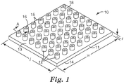
- An exemplary structured film is shown in FIG. 1 .
- Exemplary structured film 10 of FIG. 1 comprises a substantially planar film portion 11 and a plurality of tubular projections 12 extending above a first major surface 13 of substantially planar film portion 11.
- tubular projections 12 comprise a hole 15 extending from a first projection end 16 above first major surface 13 into or through substantially planar film portion 11, a projection sidewall 18 surrounding at least a portion of hole 15, and a projection length, L , extending a distance from first projection end 16 to first major surface 13.
- the structured films comprise a substantially planar film portion such as substantially planar film portion 11 of exemplary structured film 10 shown in FIG. 1 .
- the substantially planar film portion has a first major surface, a second major surface opposite the first major surface, and an average film portion thickness, t , extending from the first major surface to the second major surface.
- the term "substantially planar film portion” is used to refer to the portion of structured films, which surround and separate the plurality of tubular projections from one another.
- the substantially planar film portion has a planar film portion having an average film portion thickness, t, substantially less than either the overall width w or length l of the structured film.
- the "average film portion thickness" (designated t ) of the substantially planar film portion is determined by measuring a thickness of the substantially planar film portion at numerous locations between adjacent tubular projections resulting in a total number of film portion thicknesses, x ; and calculating the average portion thickness of the x film portion thicknesses.
- x is greater than about 3, and desirably ranges from about 3 to about 10.
- each measurement is taken at a location approximately midway between adjacent tubular projections in order to minimize any effect on the measurement by the tubular projections.
- the substantially planar film portion of the structured films has an average film portion thickness, which varies depending upon the particular end use of the structured film. Typically, the substantially planar film portion has an average film portion thickness of less than about 508 microns ( ⁇ m) (20 mils.). In some embodiments, the substantially planar film portion has an average film portion thickness of from about 50.8 ⁇ m (2.0 mils.) to about 508 ⁇ m (20 mils.). In other embodiments, the substantially planar film portion has an average film portion thickness of from about 101.6 ⁇ m (4.0 mils.) to about 254 ⁇ m (10 mils.). In yet other embodiments, the substantially planar film portion has an average film portion thickness of from about 101.6 ⁇ m (4.0 mils.) to about 152.4 ⁇ m (6.0 mils.).
- the substantially planar film portion of the structured films can comprise one or more polymeric materials.
- suitable polymeric materials include, but are not limited to, polyolefins such as polypropylene and polyethylene; olefin copolymers (for example, copolymers with vinyl acetate); polyesters such as polyethylene terephthalate and polybutylene terephthalate; polyamide (Nylon-6 and Nylon-6,6); polyurethanes; polybutene; polylactic acids; polyvinyl alcohol; polyphenylene sulfide; polysulfone; polycarbonates; polystyrenes; liquid crystalline polymers; polyethylene-co-vinylacetate; polyacrylonitrile; cyclic polyolefins; or a combination thereof.
- the substantially planar film portion comprises a polyolefin such as polypropylene, polyethylene, or a blend thereof.
- the substantially planar film portion may further comprise one or more additives as described below.
- the substantially planar film portion typically comprise at least 75 weight percent of any one of the above-described polymeric materials with up to about 25 weight percent of one or more additives.
- the substantially planar film portion comprises at least 80 weight percent, more desirably at least 85 weight percent, at least 90 weight percent, at least 95 weight percent, and as much as 100 weight percent of any one of the above-described polymeric materials, wherein all weights are based on a total weight of the substantially planar film portion.
- additives may be added to a polymer melt formed from one or more of the above-referenced polymers and extruded to incorporate the additive into the substantially planar film portion.
- the amount of additives is less than about 25 wt%, desirably, up to about 5.0 wt%, based on a total weight of the structured film.
- Suitable additives include, but are not limited to, additives such as those described above.
- the substantially planar film portion comprises a single layer of thermoformable material forming the first and second major surfaces and having the above-described average film portion thickness, wherein the thermoformable material comprises one or more of the above-mentioned polymers and optional additives.
- the substantially planar film portion comprises a single layer of thermoformable material forming the first and second major surfaces and having the above-described average film portion thickness, wherein the first and second major surfaces are exposed (for example, are not covered) so as to be positionable and/or attachable to a desired substrate.
- the structured films further comprise a plurality of tubular projections extending above the first major surface of the substantially planar film portion such as tubular projections 12 of exemplary structured film 10 shown in FIG. 1 .
- the tubular projections are desirably formed from the same thermoformable composition used to form the above-described substantially planar film portion.
- the substantially planar film portion and the plurality of tubular projections comprise a continuous, thermoformed structure formed from a single thermoformable composition comprising one or more of the above-mentioned polymers and optional additives.
- the substantially planar film portion and the plurality of tubular projections (i) comprise a continuous, thermoformed structure formed from a single thermoformable composition, and (ii) are free of post film-forming, projection-forming orientation.
- post film-forming, projection-forming orientation is used to describe conventional processes used to form projections and/or openings in a film. Such conventional processes include, but are not limited to, a thermoforming step used to form projections in a previously solidified film structure (for example, not a molten film extrudate), a needle-punching step, or other film puncturing step.
- the plurality of tubular projections may be uniformly distributed over the first major surface of the substantially planar film portion or randomly distributed over the first major surface. In some embodiments, the plurality of tubular projections are uniformly distributed over the first major surface (and optionally a corresponding portion of the second major surface) of the substantially planar film portion.
- the structured film comprises a plurality of tubular projections extending from the substantially planar film portion, wherein one or more tubular projections comprise (i) a hole extending from a first projection end above the first major surface into or through the substantially planar film portion, (ii) a projection sidewall surrounding at least a portion of the hole, the projection sidewall having an outer projection sidewall surface, an inner projection sidewall surface, and a projection sidewall thickness, and (iii) a projection length, L , extending a distance from the first projection end to the first major surface, wherein a ratio of the projection length, L , to the average film portion thickness, t , is at least about 3.5.
- the ratio of the projection length, L , to the average film portion thickness, t is at least about 4.0. In yet other embodiments, the ratio of the projection length, L , to the average film portion thickness, t , is from about 4.0 to about 10.0.
- the tubular projections may have a substantially similar projection length that varies from film to film depending on the ultimate end use of a given structured film.
- the tubular projections have a projection length, L , ranging from about 25.4 ⁇ m (1 mil) to about 1.27 cm (500 mil), more typically, from about 50.8 ⁇ m (2 mil) to about 2.54 mm (100 mil), and even more typically, from about 508 ⁇ m (20 mil) to about 1.02 mm (40 mil).
- the tubular projections may be further described in terms of their projection hole length, projection hole diameter, and projection sidewall thickness, each dimension of which may vary depending on the ultimate end use of a given structured film.
- the tubular projections have a projection hole length ranging from about 25.4 ⁇ m (1 mil) to about 1.32 cm (520 mil), more typically, from about 50.8 ⁇ m (2 mil) to about 2.79 mm (110 mil), and even more typically, from about 508 ⁇ m (20 mil) to about 1.14 mm (45 mil); a projection hole diameter ranging from about 25.4 ⁇ m (1 mil) to about 6.35 mm (250 mil), more typically, from about 25.4 ⁇ m (1 mil) to about 2.54 mm (100 mil), and even more typically, from about 25.4 ⁇ m (1 mil) to about 254 ⁇ m (10 mil); and a projection sidewall thickness ranging from about 25.4 ⁇ m (1 mil) to about 508 ⁇ m (20 mil), more typically, from about 25.4 ⁇ m (1 mil) to about 254 ⁇ m (10 mil
- the tubular projections may be further described in terms of a projection sidewall thickness in relation to the average film portion thickness, t , described above.
- at least a portion of the tubular projections have a projection sidewall thickness equal to or greater than the average film portion thickness, t , of the substantially planar film portion.
- the tubular projections may have a variety of shapes and cross-sectional configurations.
- the tubular projections have a second projection end positioned below the second major surface of the substantially planar film portion.
- the structured films comprise a plurality of tubular projections extending from the substantially planar film portion, wherein one or more tubular projections comprise (i) a hole extending from a first projection end above the first major surface into or through the substantially planar film portion, (ii) a projection sidewall surrounding at least a portion of the hole, the projection sidewall having an outer projection sidewall surface, an inner projection sidewall surface, and a projection sidewall thickness, and (iii) an end-to-end projection length extending a distance from the first projection end to a second projection end below the second major surface.
- exemplary tubular projections 12 comprise a second end 17 positioned below second major surface 14 of substantially planar film
- one or more tubular projections desirably have an upper projection length extending a distance from the first projection end to the first major surface, wherein a ratio of the upper projection length (for example, projection length, L ) to the average film portion thickness, t , is at least about 3.5. More desirably, the ratio of the upper projection length (for example, projection length, L ) to the average film portion thickness, t , is from about 4.0 to about 10.0.
- the tubular projections may have a projection sidewall thickness that varies along the projection length (for example, projection length, L , or an end-to-end projection length).
- exemplary tubular projections 12 may comprise a projection sidewall thickness that remains substantially constant along the projection length (see, for example, FIG. 2B ) or a projection sidewall thickness that varies along the projection length (see, for example, FIGS. 2A and 2C -2F).
- one or more tubular projections have a first wall thickness at a projection base located proximate the first major surface, a second wall thickness at the first projection end, and a third wall thickness at a projection midsection located between the projection base and the first projection end, wherein the first and second wall thicknesses are greater than the third wall thickness (see, for example, FIG. 2F ) .
- one or more tubular projections have a first wall thickness at a projection base located proximate the first major surface, a second wall thickness at the first projection end, and a third wall thickness at a projection midsection located between the projection base and the first projection end, wherein the first and second wall thicknesses are less than the third wall thickness (see, for example, FIG. 2E ) .
- one or more tubular projections have a first cross-sectional area above the first major surface of the substantially planar film portion, a second cross-sectional area within the substantially planar film portion, and a third cross-sectional area below the second major surface of the substantially planar film portion, wherein the first cross-sectional area is less than the second and third cross-sectional areas (see, for example, FIG. 2C ) .
- one or more tubular projections have a bubble portion (for example, bubble portion 19 shown in FIG. 2C ) in fluid communication with the hole (for example, hole 15 ) extending through the tubular projection.
- the bubble portion can be present (i) within the substantially planar film portion, (ii) below the second major surface, or (iii) both (i) and (ii) (see, for example, FIG. 2C ).
- a lower portion of the bubble portion can be removed to provide an opening extending through the structured film from the first projection end to the second projection end.
- a portion of bubble portion 19 along second end 17 of tubular projection 12 shown in FIG. 2C may be removed by cutting bubble portion 19 along dashed line B - B shown in FIG. 2C .
- tubular projections may have an outer tubular projection cross-sectional configuration that varies depending on the desired cross-sectional configuration and the type of tooling used to form the tubular projections.
- the tubular projections may have an outer tubular projection cross-sectional shape in the form of a circle, an oval, a polygon, a square, a triangle, a hexagon, a multi-lobed shape, or any combination thereof.
- one or more tubular projections have a hole (for example, hole 15 ) extending completely through the substantially planar film portion (with or without the need to remove a portion of the tubular projection as described above).
- exemplary tubular projections 12 comprise hole 15 that extends along the projection length from first projection end 16 to second projection end 17.
- a cross-sectional area of hole 15 can vary (see, for example, FIGS. 2A and 2D -2F) or remain substantially constant (see, for example, FIG. 2B ) along the projection length from first projection end 16 to second projection end 17.
- the structured film comprises a plurality of tubular projections extending from the substantially planar film portion, wherein at least a portion of the tubular projections comprise (i) a hole extending from a first projection end above the first major surface through the substantially planar film portion to a second projection end below the substantially planar film portion providing an opening through the structured film, (ii) a projection sidewall surrounding at least a portion of the hole, the projection sidewall having an outer projection sidewall surface, an inner projection sidewall surface, and a projection sidewall thickness, and (iii) an end-to-end projection length extending a distance from the first projection end to the second projection end.
- tubular projections extend substantially perpendicular to the substantially planar film portion as shown in FIGS. 2A-2F ; however, other orientations of tubular projections relative to the substantially planar film portion are within the scope of the present invention.
- the tubular projections may be present along one or both major surfaces of the substantially planar film portion of the structured film at a tubular projection density that varies depending on the desired tubular projection density, and the end use of the structured film.
- the tubular projections are present along one or both major surfaces of the substantially planar film portion of the structured film at a tubular projection density of up to about 1000 projections/cm 2 of outer surface area of the substantially planar film portion.
- the tubular projections are present along one or both major surfaces of the substantially planar film portion of the structured film at a tubular projection density of from about 10 projections/cm 2 to about 300 projections/cm 2 of outer surface area of the substantially planar film portion.
- the structured film is liquid impermeable (for example, water impermeable) and vapor permeable.
- a method of making a structured film useful in the present invention comprises extruding a sheet of molten extrudate from a die; bringing the molten extrudate into contact with a tooling so as to cause a portion of the molten extrudate to enter into a plurality of holes located on a tooling outer surface resulting in (i) an air pressure differential between a higher air pressure within one or more holes of the tooling and a lower air pressure on an outer surface of the molten extrudate opposite the tooling, and (ii) formation of a plurality of projections along a molten extrudate surface; allowing air within the one or more holes of the tooling to move in a direction toward the outer surface of the molten extrudate opposite the tooling so as to (i) reduce the air pressure differential and (ii) form a projection hole within one or more of the plurality of projections; and cooling the molten extrudate and plurality of projections to form a structured film comprising a substantially planar film portion having first
- the bringing step may comprise nipping the molten extrudate between the tooling and a nip roll, wherein the tooling comprises a tooling roll.
- the allowing step may comprise rotating the tooling roll and nip roll so that the nip roll is not positioned over the outer surface of the molten extrudate opposite the tooling.
- one or more process parameters may be adjusted so that the allowing step results in the projection hole within one or more of the tubular projections to extend from a first projection end into or through the substantially planar film portion.
- Process parameters that can be adjusted include, but are not limited to, an extrudate composition, an extrudate temperature, a tooling temperature, a tooling speed, a tooling hole depth, a molten extrudate sheet thickness, or any combination thereof.
- one or more process parameters may be adjusted so that the allowing step results in a projection hole within one or more tubular projections that extends from a first projection end into or through the substantially planar film portion so as to form a bubble portion in fluid communication with the projection hole.
- the bubble portion may be positioned (i) within the substantially planar film portion, (ii) below the second major surface of the substantially planar film portion, or (iii) both (i) and (ii).
- Process parameters that can be adjusted to form a bubble portion include, but are not limited to, an extrudate composition, an extrudate temperature, a tooling temperature, a tooling speed, a tooling hole depth, a molten extrudate sheet thickness, or any combination thereof.
- the method of making a structured film may further comprise opening the bubble portion so as to provide an opening extending completely through one or more of the tubular projections.
- the step of opening the bubble portion may comprise removing a tip of the bubble portion (for example, cutting a tip from a lower surface of the bubble portion), puncturing the bubble portion (for example, with a needle or other sharp object), pressurizing the projection hole, heating or flame-treating the tip of the bubble portion, or any combination of the above-described opening steps.
- one or more process parameters are adjusted so that the allowing step results in a projection hole within one or more tubular projections that extends from a first projection end through the substantially planar film portion so as to provide an opening extending through one or more tubular projections (for example, without the need for the above-described opening step).
- process parameters that can be adjusted to form an opening extending completely through one or more tubular projections include, but are not limited to, an extrudate composition, an extrudate temperature, a tooling temperature, a tooling speed, a tooling hole depth, a molten extrudate sheet thickness, or any combination thereof.
- one or more of the above-mentioned process parameters may be adjusted so that the allowing step results in one or more tubular projections extending from above the first major surface of the structured film to below the second major surface of the structured film.
- the method may further comprise, after the cooling step, removing at least a portion of thermoformed material below the second outer surface of the structured film, if necessary, so as to provide an opening extending completely through one or more tubular projections of the structured film from a first projection end above the first major surface to a second projection end below the second major surface.
- the method may also optional comprise a step wherein substantially all of the thermoformed material located below the second major surface of the structured film is removed so that the structured film comprises a plurality of tubular projections along only a first major surface of the structured film.
- the method of making a structured film comprises the steps of extruding molten extrudate from a die into a nip formed between a rotating tooling roll and a rotating nip roll; forcing a portion of the molten extrudate into a plurality of holes located in the rotating tooling roll resulting in (i) an air pressure differential between a higher air pressure within one or more holes of the rotating tooling roll and a lower air pressure on an outer surface of the molten extrudate opposite the rotating tooling roll, and (ii) formation of a plurality of projections along a molten extrudate surface; rotating the tooling and nip rolls so as to allow air within the one or more holes of the rotating tooling roll to move in a direction toward the outer surface of the molten extrudate opposite the rotating tooling roll so as to form a projection hole within one or more of the plurality of projections; and cooling the molten extrudate and plurality of projections to a temperature below a softening
- exemplary apparatus 30 comprises a die assembly 31 from which a molten extrudate 32 exits.
- Molten extrudate 32 proceeds to point P A where molten extrudate 32 passes between nip roll 33 rotating in a first direction as noted by arrow A 1 and tooling roll 34 rotating in an opposite direction as noted by arrow A 2 .
- nip roll 33 forces a portion of molten extrudate 32 into holes (not shown) within an outer surface 39 of tooling roll 34.
- Outer surface 38 of nip roll 33 is typically smooth and is optionally coated with a release material (for example, a silicone or PTFE).
- outer surface 38 of nip roll 33 is displaced from outer surface 36 of molten extrudate 32, which allows air within individual holes (not shown) to move through molten extrudate within the individual holes (not shown) toward outer surface 36 of molten extrudate 32 (that is, toward the lower air pressure).
- molten extrudate within individual holes (not shown) of outer surface 39 of tooling roll 34 begins to harden. It is believed that molten extrudate adjacent outer surface 39 of tooling roll 34 and individual hole sidewall surfaces hardens prior to a central portion of molten extrudate in a central location of individual holes.
- the air movement may result in (i) a hole extending into or through a substantially planar film portion of molten extrudate 32, (ii) a bubble formed within and/or below the substantially planar film portion of molten extrudate 32, (iii) a hole extending completely through the substantially planar film portion of molten extrudate 32, (iv) a second projection end below a second major surface of the substantially planar film portion of molten extrudate 32, or (v) any combination of (i) to (iv).
- molten extrudate 32 and tubular projections 12 formed therein are substantially hardened.
- outer surface 36 of substantially hardened molten extrudate 32 comes into contact with outer surface 40 of take-off roll 33 rotating in a direction as noted by arrow A 3 .
- substantially hardened molten extrudate 32 separates from outer surface 39 of tooling roll 34 and proceeds in a direction as noted by arrow A 4 along outer surface 40 of take-off roll 33 resulting in structured film 37 having tubular projections 12 therein.
- thermoforming method step involves melt extruding a film-forming thermoformable material at a melt extrusion temperature ranging from about 120°C to about 370°C.
- the disclosed methods of making structured films of the present invention can produce structured films having relatively large hole depth/hole diameter ratios.
- the disclosed methods are capable of producing structured films wherein at least a portion of the tubular projections have a projection hole length to projection hole diameter ratio of at least about 1:1.
- the disclosed methods are capable of producing structured films wherein at least a portion of the tubular projections have a projection hole length to projection hole diameter ratio of at least about 3:1, and as much as 5:1 and higher.
- the ability to provide a relatively thin substantially planar film portion allows for lower basis weight films, which can be advantageous in weight conscious applications.
- a lower basis weight for the structured films of the present invention also translates into lower raw materials usage and lower manufacturing costs.
- the disclosed methods are capable of producing structured films wherein at least a portion of the tubular projections have a projection hole length to average film portion thickness ratio of at least about 1.1:1, and in some embodiments, a projection hole length to average film portion thickness ratio of at least about 5:1, and in some embodiments, a projection hole length to average film portion thickness ratio of at least about 10:1 or higher.
- a suitable tooling may comprise a plurality of holes in an outer surface of the tooling, wherein the holes have an average tooling hole depth of up to about 1.5 cm (588 mil).
- a suitable tooling may comprise holes have an average tooling hole depth of from about 27.9 ⁇ m (1.1 mil) to about 3.0 mm (117 mil), and in other embodiments, an average tooling hole depth of from about 747 ⁇ m (29.4 mil) to about 1.5 mm (58.8 mil).
- Suitable toolings may also have holes therein, wherein the holes have one or more hole cross-sectional shapes so as to form tubular projections having a desired cross-sectional shape.
- Suitable hole cross-sectional shapes include, but are not limited to, a circle, an oval, a polygon, a square, a triangle, a hexagon, a multi-lobed shape, or any combination thereof.
- suitable toolings may have any desired density of holes along an outer surface of the tooling (for example, in outer surface 59 of tooling roll 54).
- a tooling may have a hole density of up to about 1000 holes/cm 2 of outer surface area of the tooling.
- the tooling has a hole density ranging from about 10 holes/cm 2 to about 300 holes/cm 2 of outer surface area of the tooling.
- the acoustic composites of the invention comprise acoustic barrier material.
- the acoustic barrier material shifts frequency absorption into the lower frequency range and also provides increased transmission loss.
- the flow resistive substrate has an acoustic barrier material bonded to at least a portion of at least one of its major surfaces.
- acoustic barrier material is bonded to both major surfaces of the flow resistive substrate.
- the term "bonded” includes chemical and mechanical means for acoustically coupling (that is, joining and securing) the acoustic barrier material to the substrate.
- the acoustic barrier material is distributed within the flow resistive substrate (that is, the acoustic barrier material is "inside" the film).
- Acoustic barrier materials for use in the acoustic composites of the invention have a density greater than about 1 g/cm 3 (preferably greater than about 2 g/cm 3 ; more preferably greater than about 4 g/cm 3 ).
- Suitable acoustic barrier materials include, for example, metals, metal alloys, metal oxides, glass, silicates, minerals, sulfides, clay, bitumen, calcium carbonate, barium sulfate, loaded polymers, and the like.
- the acoustic barrier material can be in any useful form.
- the acoustic barrier can a particle, granule, or bead.
- the acoustic barrier material can also, for example, be a continuous layer of mass comprising holes (that is, a "contiguous layer") such as a metal foil comprising holes.
- the acoustic barrier material is selected from the group consisting of metal particles, glass particles, and combinations thereof; more preferably, the acoustic barrier is a steel particle or a glass particle.
- the acoustic barrier material is a layer comprising a polymer such as, for example, ethylene propylene diene M-class rubber (EPDM), ethylene vinyl acetate (EVA), or olefin-based polymers filled with particles having a higher density than the polymer.
- Suitable filler particles can comprise any of the materials described above as suitable acoustic barrier materials.
- the filler particles have a density in greater than about 1 g/cm 3 (preferably, greater than about 2 g/cm 3 ; more preferably, greater than about 4 g/cm 3 ).
- Examples of preferred filler particles include calcium carbonate, barium sulfate, and other mineral-based particles with a density greater than about 1 g/cm 3 .
- the density of the polymer with the filler particles is typically from about 7.18 Pa (0.15 lb/ft 2 ) to about 71.82 Pa (1.5 lb/ft 2 ).
- An acoustic barrier material layer (including, but not limited to, polymeric acoustic barrier material layers containing filler particles) can comprise holes or perforations.
- the holes or perforations can be in any shape but are preferably relatively circular in shape. Preferably, they have a diameter from about 3 mm to about 20 mm and are about 10 to about 300 times larger in diameter than the planar microperforated film described above.
- the porosity, or percent open area, of this acoustic barrier material layer typically ranges from about 10% to about 60%.
- Acoustic composites known as a "leaky barrier” can be made by bonding (for example, laminating) the above-described acoustic barrier material layer comprising holes or perforations to a flow resistive substrate.
- the porosity of the acoustic composite is therefore a function of the porosity of the acoustic barrier material layer multiplied by the porosity of the flow resistive substrate.
- the porosity of the leaky barrier acoustic composite is about 0.06% to about 50% (more preferably, about 0.06% to about 30%; even more preferably, about 0.06% to about 10%).
- the acoustic barrier material can be bonded to the flow resistive substrate using any suitable binder.
- suitable binder include thermoplastic resins such as ethylene/acrylic acid copolymer, polyethylene, and poly(ethylmethylacrylic) acid; acrylic pressure-sensitive adhesives which cure to a nontacky state; and thermosetting binders which have a tacky state such as epoxy resins, phenolics, and polyurethanes.
- the binder is an epoxy binder.
- the binder is typically prepared from a curable binder precursor.
- the curable binder precursor can comprise organic thermosetting and/or thermoplastic material, although this is not a requirement.
- the binder precursor is capable of being cured by radiation energy or thermal energy. Sources of radiation energy include electron beam energy, ultraviolet light, visible light, and laser light. If ultraviolet or visible light is utilized a photoinitiator may be utilized.
- thermosetting curable binder precursors include, for example, phenolic resins, polyester resins, copolyester resins, polyurethane resins, polyamide resins, and mixtures thereof.
- Useful temperature-activated thermosetting binder precursors include formaldehyde-containing resins such as phenol formaldehyde, novolac phenolics (preferably those with added crosslinking agents), phenoplasts, and aminoplasts; unsaturated polyester resins; vinyl ester resins; alkyl resins, allyl resins; furan resins; epoxies; polyurethanes; cyanate esters; and polyimides.
- binder precursors that are capable of being cured by radiation energy include acrylated urethanes, acrylated epoxies, ethylenically unsaturated compounds, aminoplast derivatives having pendant acrylate groups, isocyanate derivatives having at least one pendant acrylate group, vinyl ethers, epoxy resins, and combinations thereof.
- thermoplastic curable binder precursors include polyolefin resins such as polyethylene and polypropylene; polyester and copolyester resins; vinyl resins such as polyvinylchloride and vinyl chloride-vinyl acetate copolymers; polyvinyl butyral; cellulose acetate; acrylic resins including polyacrylic and acrylic copolymers such as acrylonitrile-styrene copolymers; and polyamides, co-polyamides, and combinations thereof
- the acoustic barrier material can be mixed with a binder (or binder precursor) and then added to a surface of the flow resistive substrate.
- a binder or binder precursor
- a binder or binder precursor
- the binder can be patterned in any desired pattern (for example, a dot or stripe pattern).
- a pattern can be obtained, for example, by applying the binder (or binder precursor) through stencil holes or a screen.
- Binder (or binder precursor) can also be coated onto the flow resistive substrate using rotary screen printing, roll coating, die coating, mechanical placement of agglomerates, or by any means known in the art.
- the acoustic barrier material and the binder together cover between about 20 % and about 99.98 % of the major surface of the flow resistive substrate (preferably between about 20% and about 99.5%).
- polymeric material comprising the acoustic barrier material can be extruded, calendared and/or pressed.
- the method of U.S. Patent No. 4,486,200 (Heyer et al. ) can also be used for making acoustic composites with barrier material distributed with the flow resistive substrate.
- the acoustic composites of the invention typically have a porosity between about 0.002 % and about 50 % (preferably, between about 0.5 % and about 50 %; more preferably between about 0.5 % and about 15 %).
- the porosity of the acoustic composite is a function of both the porosity of the (naked) flow resistive substrate and the coverage of the binder and acoustic barrier material.
- the materials selected when designing an acoustic composite or acoustic composite system can also affect non-acoustic properties.
- the acoustic composites of the invention can provide one or more of the following properties: radio frequency, heat transfer, heat reflection, conductivity (electrical, thermo, or light), non-conductivity (electrical, thermo, or light), electromagnetic waves, light reflection or transmission, flame retardance, flexibility, or stretchablity.
- the acoustic composites of the invention can comprise one or more optional layers.
- Suitable additional layers include, but are not limited to, a fabric layer (for example, woven, non-woven, and knitted fabrics); a paper layer; a color-containing layer (for example, a print layer); a sub-micron fiber layer such as those disclosed in U.S. Patent Application Serial No. 60/728,230 ; foams; layers of particles; foil layers; films; decorative fabric layers; membranes (that is, films with controlled permeability, such as dialysis membranes, reverse osmosis membranes, etc.); netting; mesh; wiring and tubing networks; or a combination thereof.
- the one or more additional layers may be present (i) on and/or in contact with tubular projection ends extending above the first major surface of the substantially planar film portion of the structured film (for example, first projection ends), (ii) on and/or in contact with tubular projection ends extending below the second major surface of the substantially planar film portion (for example, second projection ends), (iii) on and/or in contact with the second major surface of the substantially planar film portion (for example, second major surface), (iv) both (i) and (ii), or (v) both (i) and (iii).
- the acoustic composites of the invention can be disposed near a reflecting surface to define a cavity therebetween.
- the cavity can be purely an air gap or it can comprise, for example, a non-woven material.
- the depth of the cavity will typically depend upon the frequency range in which the acoustic composite will be utilized. Increasing the cavity depth, for example, shifts the frequency curve for absorption to lower frequencies., In general, though, the depth of the cavity will range from about 0.3 cm (1/8 inch) to about 15 cm (6 inches) (preferably, about 0.3 cm (1/8 inch) to about 2.5 cm (1 inch)).
- the acoustic composite can be disposed near the reflecting surface in a number of ways.
- the acoustic composite can be attached to a structure which includes the reflecting surface.
- the acoustic composite can be attached on its edges and/or its interior.
- the acoustic composite can also be hung, similar to a drape, from a structure near the reflecting surface.
- a spacing structure (for example, a honeycomb structure) can be placed between the acoustic composite and the reflecting surface.
- the reflecting surface can be for example, a surface of an automobile (for example, an automobile hood, dashboard, or underbelly surface), a wall or ceiling or a building, a window, or the like.
- the reflecting surface could also be a metal plate or a backing film.
- the acoustic composite can be provided as part of a layered construction comprising a layer of carpet, the acoustic composite, and a non-woven layer.
- the non-woven layer comprises shoddy (for example, fibrous material made from fabric scraps or shredded rags).
- the layered construction can further comprise a metal plate. Often the metal plate is an integral part of the automobile. Such layered constructions provide good acoustic performance in a relatively light weight system.
- a method of using the acoustic composite comprises a method for providing acoustic absorption and transmission loss in an area, wherein the method comprises surrounding at least a portion of the area with an acoustic composite of the invention.
- the acoustic composite can provide about 50 % or more acoustic absorption for frequencies ranging from about 500 Hz (preferably, from about 400 Hz; more preferably from about 250 Hz; most preferably, from about 100 Hz) to about 4000 Hz.
- the acoustic composite can also provide acoustic transmission loss ranging from about 3 dB to about 30 dB for frequencies ranging from about 500 Hz (preferably, from about 400 Hz; more preferably from about 250 Hz; most preferably, from about 100 Hz) to about 4000 Hz.
- an entire area may be surrounded by the acoustic composite alone or in combination with one or more optional layers as described above.
- the step of surrounding an area may comprise positioning the acoustic composite over at least a portion of the area.
- the surrounding step may comprise positioning the acoustic composite or composite system over at least a portion of the area.
- the surrounding step may further comprise the step of attaching the acoustic composite or composite system to a substrate. Any of the above-described attachment methods may be used to attach the acoustic composite or composite system to a given substrate.
- Suitable substrates may include, but are not limited to, a wall of a building, a ceiling of a building, a building material for forming a wall or ceiling of a building, a metal sheet, a glass substrate, a door, a window, a vehicle component, a machinery component, an electronic device (for example, printers, hard drives, etc.), or an appliance component.
- a method of using the acoustic composite comprises a method for providing acoustic absorption and transmission loss between a sound-generating object and an area.
- the method may comprise providing an acoustic composite between the sound-generating object and the area.
- the acoustic composite can provide about 50 % or more acoustic absorption for frequencies ranging from about 500 Hz (preferably, from about 400 Hz; more preferably from about 250 Hz; most preferably, from about 100 Hz) to about 4000 Hz.
- the acoustic composite can also provide acoustic transmission loss ranging from about 3 dB to about 30 dB for frequencies ranging from about 500 Hz (preferably, from about 400 Hz; more preferably from about 250 Hz; most preferably, from about 100 Hz) to about 4000 Hz.
- the sound-generating object may be any object that generates sound including, but not limited to, a vehicle motor, a piece of machinery, an appliance motor or other moving component, an electronic device such as a television, an animal, etc.
- the area in either of the above exemplary methods of using an acoustic composite of the invention may be any area in which sound is to be absorbed and/or restricted from. Suitable areas may include, but are not limited to, an interior of a room; an interior of or other location in a vehicle; a piece of machinery; an appliance; a separate sound reduced area of an office or industrial area; a sound recording or reproduction area; the interior of a theatre or concert hall; an anechoic, analytical or experimental room or chamber where sound would be detrimental; and earmuffs or ear covering for isolating and/or protecting ears from noise.
- the acoustic composites of the present invention may also be used as a resistive membrane layer in a carpet system.
- one or more layers of fabric are attached to each side of the acoustic composite to form a laminate.
- Examples 1 and 2 Micro-Perforated Film with SS Beads (Example 1) or Glass Beads (Example 2)
- Microperforated film as a substrate was primed with 1% solution of epoxy resin (Scotch-Weld DP 100) solution in acetone. Then the film was dried at room temperature in the air vented hood for 4 hours.
- the primed film 17.8 cm (7 inches) by 17.8 cm (7 inches) was laid on a flat surface, then covered by the metal screen, which was mold release treated (Rocket Release, E302, Stoner, Inc. (Quarryville, PA)).
- An epoxy resin mixture weighing 18 g was mixed and 140 g of stainless steel beads (or 80 g of glass beads) was mixed into the epoxy resin. Quickly after mixing, the resulting mixture was poured over the metal screen and the extra was removed using a scraper.
- Example 1 The resulting acoustic composite of Example 1 is shown in FIG. 4 at 5X magnification. Glass beads based: Weight gain: 422 g/m 2 Steel beads based: Weight gain: 1899 g/m 2
- Examples 3 and 4 Resistive Non-woven Scrim with SS Beads (Example 3) or Glass Beads (Example 4)
- Resistive scrim samples 17.8 cm (7 inches) by 17.8 cm (7 inches) were laid on a flat surface, then covered by the metal screen, which was mold release treated (Rocket Release, E302).
- An epoxy resin mixture weighing 18 g was mixed and 140 g of stainless steel beads (or 80 g of glass beads) was mixed into the epoxy resin.
- the resulting mixture was poured over the metal screen and the extra was removed using a scraper.
- the metal screen was removed from the substrate.
- the film with metal/epoxy printed on was further cured at room temperature for 2 hours before any further processing.
- a 120 mm diameter circle was cut from the EPDM rubber sheet and also from the Mirco-Perforated Film. Then 12.7 mm for Ex. 5 (19.05mm for Ex. 6, 6.35 mm for Ex. 7) diameter holes were punched out of the EPDM sheet using a steel rule die. The number of holes ranged from 12 holes for Ex. 5 (6 holes for Ex. 6, 40 holes for Ex.7) and were symmetrically distributed around the center and within a 100 mm diameter area of the 120 mm EPDM rubber circle. The resulting porosity for Ex. 5 was approximately 0.07%. The resulting porosity for example 6 was approximately 0.08%. The resulting porosity for example 7 was approximately 0.06%. Then the EPDM circle with holes was sprayed with the spray adhesive.
- the micro-perforated film was placed on top of the EPDM rubber layer.
- the micro-perforated film and EPDM rubber with pressure sensitive adhesive was then placed between two stainless steel sheets then weight (approximately 9.07 kg) was placed on the top stainless steel sheet for more than 5 hours.
- a 120 mm diameter circle was cut from the Mirco-Perforated Film. Then approximately 3-4 sheets of the box sealing tape was applied on the Micro-Perforated Film to cover a majority of the Micro-Perforated Film area, approximately 99.998% of the area was covered. The pressure sensitive side was placed against the Micro-Perforated Film surface. The approximately 0.002% porosity was placed towards the center of the innermost 100 mm diameter circle area.
Claims (15)
- Akustisches Verbundmaterial, umfassend:ein strömungsbeständiges Substrat (10) mit einem festen akustischen Barrierematerial, das mit mindestens einem Abschnitt einer Hauptoberfläche des strömungsbeständigen Substrats verbunden ist; wobei das akustische Barrierematerial eine Dichte von mehr als ungefähr 1 g/cm3 aufweist und das akustische Verbundmaterial eine Porosität zwischen ungefähr 0,002 % und ungefähr 50 % aufweist und wobei das akustische Barrierematerial die Frequenzabsorption in den unteren Frequenzbereich verschiebt und einen größeren Klangübertragungsverlust bereitstellt.
- Akustisches Verbundmaterial, umfassend:ein strömungsbeständiges Substrat (10) mit einem festen akustischen Barrierematerial, das mit einem Bindemittel mit mindestens einem Abschnitt einer Hauptoberfläche des strömungsbeständigen Substrats verbunden ist; wobei das akustische Barrierematerial eine Dichte von mehr als ungefähr 1 g/cm3 aufweist und wobei die Barriere und das Bindemittel zusammen zwischen ungefähr 20 % und ungefähr 99,998 % der Hauptoberfläche bedecken, und wobei das akustische Barrierematerial die Frequenzabsorption in den unteren Frequenzbereich verschiebt und einen größeren Klangübertragungsverlust bereitstellt.
- Akustisches Verbundmaterial nach einem der vorstehenden Ansprüche, wobei das strömungsbeständige Substrat ein Vlies oder eine mikroperforierte Folie (10) umfasst.
- Akustisches Verbundmaterial nach Anspruch 3, wobei das strömungsbeständige Substrat eine polymere mikroperforierte Folie (10) ist, die mehrere Mikroperforationen (15) umfasst, wobei die Mikroperforationen jeweils einen kleinsten Durchmesser aufweisen, der kleiner ist als die Foliendicke, und einen größten Durchmesser, der größer ist als der kleinste Durchmesser.
- Akustisches Verbundmaterial nach Anspruch 3, wobei das strömungsbeständige Substrat (10) eine mikroperforierte Folie (10) ist, die Folgendes umfasst:einen im Wesentlichen ebenen Folienabschnitt (11) mit einer ersten Hauptoberfläche (13), einer zweiten Hauptoberfläche (14) und einer durchschnittlichen Folienabschnittsdicke; undmehrere rohrförmige Vorsprünge (12), die sich vom im Wesentlichen ebenen Folienabschnitt (11) erstrecken, wobei eine oder mehrere rohrförmige Vorsprünge ein Loch (15) umfassen.
- Akustisches Verbundmaterial nach Anspruch 5, wobei eine oder mehrere der rohrförmigen Vorsprünge (12) Folgendes umfassen:(i) ein Loch (15), das sich von einem ersten Vorsprungsende (16) über der ersten Hauptoberfläche (13) in oder durch den im Wesentlichen ebenen Folienabschnitt (11) erstreckt,(ii) eine Vorsprungsseitenwand (18), die mindestens einen Abschnitt des Lochs (15) umgibt, wobei die Vorsprungsseitenwand eine äußere Vorsprungsseitenwand-Oberfläche, eine innere Vorsprungsseitenwand-Oberfläche und eine Vorsprungsseitenwand-Dicke aufweist, und(iii) eine Vorsprungslänge, die sich über einen Abstand vom ersten Vorsprungsende (16) zur ersten Hauptoberfläche (13) erstreckt, wobei ein Verhältnis der Vorsprungslänge zur durchschnittlichen Folienabschnittsdicke mindestens ungefähr 3,5 beträgt.
- Akustisches Verbundmaterial nach Anspruch 5, wobei der im Wesentlichen ebene Folienabschnitt (11) ein thermisch formbares Material umfasst und eine oder mehrere der rohrförmigen Vorsprünge (12) Folgendes umfassen:(i) ein Loch (15), das sich von einem ersten Vorsprungsende (16) über der ersten Hauptoberfläche (13) in oder durch den im Wesentlichen ebenen Folienabschnitt (11) erstreckt,(ii) eine Vorsprungsseitenwand, die mindestens einen Abschnitt des Lochs (15) umgibt, wobei die Vorsprungsseitenwand das thermisch formbare Material umfasst und eine äußere Vorsprungsseitenwand-Oberfläche, eine innere Vorsprungsseitenwand-Oberfläche und eine Vorsprungsseitenwand-Dicke aufweist, und(iii) eine durchgehende Vorsprungslänge, die sich über einen Abstand vom ersten Vorsprungsende (16) zu einem zweiten Vorsprungsende (17) unter der zweiten Hauptoberfläche (14) erstreckt.
- Akustisches Verbundmaterial nach Anspruch 5, wobei der im Wesentlichen ebene Folienabschnitt (11) ein thermisch formbares Material umfasst und wobei mindestens ein Abschnitt der rohrförmigen Vorsprünge (12) Folgendes umfasst:(i) ein Loch (15), das sich von einem ersten Vorsprungsende (16) über der ersten Hauptoberfläche (13) in oder durch den im Wesentlichen ebenen Folienabschnitt (11) zu einem zweiten Vorsprungsende (17) unter dem im Wesentlichen ebenen Folienabschnitt (11) erstreckt und eine Öffnung durch die strukturierte Folie bereitstellt,(ii) eine Vorsprungsseitenwand, die mindestens einen Abschnitt des Lochs (15) umgibt, wobei die Vorsprungsseitenwand das thermisch formbare Material umfasst und eine äußere Vorsprungsseitenwand-Oberfläche, eine innere Vorsprungsseitenwand-Oberfläche und eine Vorsprungsseitenwand-Dicke aufweist, und(iii) eine durchgehende Vorsprungslänge, die sich über einen Abstand vom ersten Vorsprungsende (16) zum zweiten Vorsprungsende (17) erstreckt.
- Akustisches Verbundmaterial nach einem der Ansprüche 5-8, wobei das strömungsbeständige Substrat (10) flüssigkeitsundurchlässig und dampfdurchlässig ist.
- Akustisches Verbundmaterial nach einem der vorstehenden Ansprüche, wobei das akustische Barrierematerial Teilchen umfasst, die aus der Gruppe bestehend aus Metallteilchen, Glasteilchen und Kombinationen davon ausgewählt sind.
- Akustisches Verbundmaterial nach einem der vorstehenden Ansprüche, wobei das akustische Barrierematerial mit einem diskontinuierlichen Bindemittelüberzug mit dem strömungsbeständigen Substrat (10) verbunden ist, wobei das Bindemittel optional ein Epoxid-Bindemittel ist.
- Akustisches Verbundmaterial nach einem der vorstehenden Ansprüche, wobei das akustische Barrierematerial eine zusammenhängende Schicht ist, die Löcher umfasst.
- Akustisches Verbundmaterial nach einem der vorstehenden Ansprüche, wobei das akustische Barrierematerial Füllstoffteilchen umfasst.
- Akustisches Verbundmaterial nach einem der vorstehenden Ansprüche, ferner umfassend eine oder mehrere Schichten, die ein Gewebe oder Vlies oder einen Gewebe- oder Vlies-Schaumstoff umfassen.
- Verfahren zum Bereitstellen von akustischer Absorption und Übertragungsverlust in einem Bereich, der mindestens einen Abschnitt des Bereichs mit einem akustischen Verbundmaterial nach einem der vorstehenden Ansprüche umgibt, wobei das akustische Verbundmaterial für Frequenzen im Bereich von ungefähr 100 Hz bis ungefähr 4000 Hz einen akustischen Übertragungsverlust im Bereich von ungefähr 3 dB bis ungefähr 30 dB und eine akustische Absorption von mindestens ungefähr 50 % bereitstellt.
Applications Claiming Priority (2)
| Application Number | Priority Date | Filing Date | Title |
|---|---|---|---|
| US5052608P | 2008-05-05 | 2008-05-05 | |
| PCT/US2009/042824 WO2009137466A2 (en) | 2008-05-05 | 2009-05-05 | Acoustic composite |
Publications (3)
| Publication Number | Publication Date |
|---|---|
| EP2307627A2 EP2307627A2 (de) | 2011-04-13 |
| EP2307627A4 EP2307627A4 (de) | 2014-08-20 |
| EP2307627B1 true EP2307627B1 (de) | 2017-09-27 |
Family
ID=41265348
Family Applications (1)
| Application Number | Title | Priority Date | Filing Date |
|---|---|---|---|
| EP09743452.6A Active EP2307627B1 (de) | 2008-05-05 | 2009-05-05 | Akustisches verbundmaterial |
Country Status (7)
| Country | Link |
|---|---|
| US (1) | US8381872B2 (de) |
| EP (1) | EP2307627B1 (de) |
| JP (2) | JP5872895B2 (de) |
| KR (2) | KR101718546B1 (de) |
| CN (1) | CN102016194B (de) |
| BR (1) | BRPI0912585B1 (de) |
| WO (1) | WO2009137466A2 (de) |
Families Citing this family (37)
| Publication number | Priority date | Publication date | Assignee | Title |
|---|---|---|---|---|
| US9029033B2 (en) * | 2010-10-08 | 2015-05-12 | GM Global Technology Operations LLC | Composite end cell thermal barrier with an electrically conducting layer |
| EP2579248A3 (de) * | 2011-10-07 | 2016-12-07 | akustik & innovation gmbh | Verfahren zur Herstellung einer zwei- oder dreischichtigen schalldämmenden Platte und entsprechende schalldämmende Platte |
| DE102012210522A1 (de) * | 2012-06-21 | 2013-12-24 | Robert Bosch Gmbh | Dämpfungselement zur Dämpfung von Schwingungen, Schallwandleranordnung mit einem Dämpfungselement sowie Verfahren zur Herstellung eines Dämpfungselements |
| CN105813834B (zh) * | 2013-12-12 | 2018-10-16 | 3M创新有限公司 | 聚合物多层膜及其制备方法 |
| US9962851B2 (en) | 2013-12-12 | 2018-05-08 | 3M Innovative Properties Company | Method of making polymeric multilayer films |
| DE102013226792A1 (de) * | 2013-12-19 | 2015-06-25 | Volkswagen Aktiengesellschaft | Verfahren zur akustischen und/oder fluidtechnischen Perforation eines aus einem Faserverbundkunststoff hergestellten Bauteils |
| US9251778B2 (en) | 2014-06-06 | 2016-02-02 | Industrial Technology Research Institute | Metal foil with microcracks, method of manufacturing the same, and sound-absorbing structure having the same |
| CN104064175B (zh) * | 2014-07-10 | 2017-05-10 | 中国科学院电子学研究所 | 仿生降噪膜片 |
| JP2016107977A (ja) * | 2014-12-03 | 2016-06-20 | 現代自動車株式会社Hyundai Motor Company | 共鳴構造不織布を用いたフードインシュレーター及びこれの製造方法 |
| JP6043407B2 (ja) * | 2015-02-27 | 2016-12-14 | 富士フイルム株式会社 | 防音構造、及び防音構造の製造方法 |
| DE112016002615T5 (de) * | 2015-06-09 | 2018-03-08 | Asahi Glass Company, Limited | Folie und schallabsorbierende Struktur |
| US10098520B2 (en) * | 2016-03-09 | 2018-10-16 | Whirlpool Corporation | Dishwasher with a multi-layer acoustic material in a condensing drying system |
| JP2018009968A (ja) * | 2016-06-30 | 2018-01-18 | 株式会社Screenホールディングス | ウェルプレート及びその使用方法 |
| CN106205586B (zh) * | 2016-07-11 | 2019-10-01 | 武汉理工大学 | 一种金属基泡沫填充低频宽带隙弹性超材料 |
| IT201600073012A1 (it) * | 2016-07-13 | 2018-01-13 | Diadora Sport S R L | Struttura di intersuola per calzature |
| CN107962847B (zh) * | 2016-10-19 | 2020-06-26 | 泽费罗斯股份有限公司 | 声学吸收体复合隔板组件 |
| JP2020056803A (ja) * | 2017-01-26 | 2020-04-09 | 太陽化学株式会社 | 吸音材 |
| FR3065570B1 (fr) * | 2017-04-21 | 2019-05-03 | Office National D'etudes Et De Recherches Aerospatiales | Garniture surfacique pour absorption acoustique |
| EP3638395A4 (de) * | 2017-06-14 | 2021-03-03 | 3M Innovative Properties Company | Akustisch aktive materialien |
| CA2982731C (en) * | 2017-10-17 | 2018-07-17 | 9236-3135 Qc Inc. | Vibration absorption device and method for acoustic insulation |
| CN108231053A (zh) * | 2018-03-13 | 2018-06-29 | 吉林大学 | 一种具有凸包形态的声学包装材料及其制备方法 |
| EP3848926B1 (de) * | 2018-09-06 | 2024-03-06 | Mitsubishi Chemical Corporation | Schalldämmendes plattenelement und schalldämmende struktur damit |
| JP7310120B2 (ja) * | 2018-11-05 | 2023-07-19 | ヤマハ株式会社 | 吸音構造体 |
| JP7172457B2 (ja) | 2018-11-05 | 2022-11-16 | ヤマハ株式会社 | 吸音用ユニットおよび吸音構造体 |
| GB201819321D0 (en) * | 2018-11-27 | 2019-01-09 | Carbon Air Ltd | Cavities and active regions |
| FR3088848B1 (fr) * | 2018-11-28 | 2020-12-04 | Airbus Operations Sas | Procédé de fabrication d’un élément acoustique d’une structure d’absorption acoustique à partir d’au moins une feuille de matière |
| RU2018146623A (ru) * | 2018-12-26 | 2020-06-26 | 3М Инновейтив Пропертиз Компани | Акустическое изделие, способ его изготовления и применения |
| KR102059768B1 (ko) * | 2019-01-18 | 2019-12-26 | 임창섭 | 건축 마감용 패널 및 코너 패널 |
| US10837169B2 (en) * | 2019-03-14 | 2020-11-17 | Hilti Aktiengesellschaft | Method and apparatus for producing a tubular sealing element |
| CN109914630B (zh) * | 2019-03-22 | 2020-12-18 | 嘉兴管通机电科技有限公司 | 复合式密封型不锈钢钢板 |
| US20200388265A1 (en) * | 2019-06-10 | 2020-12-10 | Toyota Motor Engineering & Manufacturing North America, Inc. | Sound isolation device |
| US11557271B2 (en) * | 2019-11-11 | 2023-01-17 | Toyota Motor Engineering & Manufacturing North America, Inc. | Degenerative sound isolation device |
| TWI737065B (zh) | 2019-12-05 | 2021-08-21 | 財團法人工業技術研究院 | 隔音構件 |
| US11713130B2 (en) * | 2020-05-15 | 2023-08-01 | The Boeing Company | Method for using contour correct thermoplastic core in bonded acoustic panel assembly |
| IT202100001274A1 (it) * | 2021-01-25 | 2022-07-25 | Phononic Vibes S R L | Elemento per la realizzazione di un pannello insonorizzante modulare |
| CN113304709B (zh) * | 2021-06-22 | 2023-01-13 | 万华化学(四川)有限公司 | 一种脱挥装置及san树脂脱挥工艺 |
| WO2023285163A1 (de) * | 2021-07-13 | 2023-01-19 | Carcoustics Techconsult Gmbh | Akustisch wirksames bauteil, akustisch wirksame formteile, verfahren zur herstellung eines akustisch wirksamen bauteils sowie akustisch wirksamer formteile, vorteilhafte verwendungen eines akustisch wirksamen bauteils bzw. akustisch wirksamer formteile |
Family Cites Families (69)
| Publication number | Priority date | Publication date | Assignee | Title |
|---|---|---|---|---|
| US1961374A (en) * | 1930-03-10 | 1934-06-05 | Mazer Jacob | Sound-absorbing structure |
| US2573482A (en) * | 1945-04-25 | 1951-10-30 | Thomas L Fawick | Sound-deadening unit |
| US2923372A (en) * | 1952-04-22 | 1960-02-02 | Maccaferri Mario | Acoustic tile |
| US2840179A (en) * | 1954-06-17 | 1958-06-24 | Miguel C Junger | Sound-absorbing panels |
| US2984312A (en) * | 1959-04-24 | 1961-05-16 | Owens Corning Fiberglass Corp | Acoustical wall board |
| US3026224A (en) * | 1959-05-01 | 1962-03-20 | Fabreeka Products Co | Vibration absorbing pad |
| US3231454A (en) * | 1961-04-14 | 1966-01-25 | Cadillac Products | Cushioning material |
| US3174580A (en) * | 1961-04-28 | 1965-03-23 | Kurt W Schulz | Acoustical tile construction |
| US3649430A (en) * | 1965-10-21 | 1972-03-14 | American Cyanamid Co | Vibration damping laminates |
| US3597891A (en) * | 1969-10-02 | 1971-08-10 | Mc Donnell Douglas Corp | Interior absorptive panel |
| US3656576A (en) * | 1970-11-19 | 1972-04-18 | Gunter Gubela | Noise shield panels and method of fabrication |
| DE2104548A1 (de) * | 1971-02-01 | 1972-08-24 | Schoeller & Co KG, 3400 Göttingen | Quaderartiges Lärmschutzbauelement |
| US3819007A (en) * | 1973-04-27 | 1974-06-25 | Lockheed Aircraft Corp | Controllable laminar sound absorptive structure |
| US3887031A (en) * | 1973-06-11 | 1975-06-03 | Lockheed Aircraft Corp | Dual-range sound absorber |
| IT1048504B (it) * | 1974-06-27 | 1980-12-20 | Tanzilli Umberto | Elemento a.z in plastica per composizione bancali,pedane,pavimentazioni e sottopavimenti ad isolamento termico,acustico ed elettrico |
| JPS524615A (en) | 1975-06-23 | 1977-01-13 | Asahi Chemical Ind | Sound insulation panel |
| US4106587A (en) * | 1976-07-02 | 1978-08-15 | The United States Of America As Represented By The Administrator Of The National Aeronautics And Space Administration | Sound-suppressing structure with thermal relief |
| JPS5312970A (en) * | 1976-07-21 | 1978-02-06 | Nissan Motor | Process for molding packing material of corrugated cardboard |
| US4231447A (en) * | 1978-04-29 | 1980-11-04 | Rolls-Royce Limited | Multi-layer acoustic linings |
| US4486200A (en) | 1980-09-15 | 1984-12-04 | Minnesota Mining And Manufacturing Company | Method of making an abrasive article comprising abrasive agglomerates supported in a fibrous matrix |
| US4355489A (en) | 1980-09-15 | 1982-10-26 | Minnesota Mining And Manufacturing Company | Abrasive article comprising abrasive agglomerates supported in a fibrous matrix |
| US4533583A (en) * | 1981-05-22 | 1985-08-06 | May Michael G | Thermal insulating mat |
| DE3233654C2 (de) * | 1982-09-10 | 1986-01-16 | Ewald Dörken AG, 5804 Herdecke | Schallabsorbierendes Bauelement |
| DE3412846A1 (de) * | 1984-04-05 | 1985-10-17 | Hoechst Ag, 6230 Frankfurt | Flaechenfoermiger sandwichformkoerper |
| US4607466A (en) * | 1984-05-29 | 1986-08-26 | Allred John C | Method and apparatus for controlling reverberation of sound in enclosed environments |
| DE3530867A1 (de) * | 1985-08-29 | 1987-03-05 | Nuedling Franz C Basaltwerk | Mauerwerk- oder pflasterstein aus beton oder dergleichen |
| US4803112A (en) * | 1986-04-24 | 1989-02-07 | Hayakawa Rubber Co., Ltd. | Impact-cushioning sheets and direct-applying restraint type floor damping structures using the same |
| US4930266A (en) | 1988-02-26 | 1990-06-05 | Minnesota Mining And Manufacturing Company | Abrasive sheeting having individually positioned abrasive granules |
| DE69007566T2 (de) * | 1989-07-18 | 1994-06-30 | Mitsui Petrochemical Ind | Nichtgewebter Stoff und Verfahren zu seiner Herstellung. |
| US5233767A (en) * | 1990-02-09 | 1993-08-10 | Hy Kramer | Article of footwear having improved midsole |
| CH681973A5 (de) * | 1990-07-19 | 1993-06-30 | Matec Holding | |
| US5004070A (en) * | 1990-08-16 | 1991-04-02 | Wang Hong Jen | Acoustic board |
| US5258585A (en) * | 1991-02-20 | 1993-11-02 | Indian Head Industries, Inc. | Insulating laminate |
| US5445861A (en) * | 1992-09-04 | 1995-08-29 | The Boeing Company | Lightweight honeycomb panel structure |
| JP3076945B2 (ja) * | 1993-06-15 | 2000-08-14 | 松下電器産業株式会社 | 吸音装置 |
| JPH07140985A (ja) * | 1993-11-18 | 1995-06-02 | Nippon Micro Kooteingu Kk | 吸音体 |
| US6213252B1 (en) * | 1996-11-08 | 2001-04-10 | Royal Mat International Inc. | Sound absorbing substrate |
| JP3119192B2 (ja) * | 1997-03-07 | 2000-12-18 | 日産自動車株式会社 | 遮音板構造 |
| CN2316357Y (zh) * | 1997-12-10 | 1999-04-28 | 北京市劳动保护科学研究所 | 穿孔衬板复合微穿孔薄膜吸声结构 |
| JPH11348163A (ja) * | 1998-06-03 | 1999-12-21 | Mitsui Chem Inc | 吸収性物品用バックシート材 |
| US6617002B2 (en) | 1998-07-24 | 2003-09-09 | Minnesota Mining And Manufacturing Company | Microperforated polymeric film for sound absorption and sound absorber using same |
| US6977109B1 (en) | 1998-07-24 | 2005-12-20 | 3M Innovative Properties Company | Microperforated polymeric film for sound absorption and sound absorber using same |
| EP1020846B1 (de) * | 1999-01-14 | 2018-09-19 | Nichias Corporation | Schallabsorbierende Struktur |
| US6627791B1 (en) * | 1999-04-01 | 2003-09-30 | The Procter & Gamble Company | Resilient, three dimensional polymeric film comprising open and closed capillaries, and absorbent article with improved backsheet comprising the film |
| JP2001249665A (ja) * | 2000-03-07 | 2001-09-14 | Tokyo Eruguude Kk | 吸音材 |
| US7059089B1 (en) | 2000-03-20 | 2006-06-13 | Newmat, Sa | Flexible sheet materials for tensioned structures, a method of making such materials, and tensioned false ceilings comprising such materials |
| US6786013B2 (en) * | 2000-06-14 | 2004-09-07 | Benjamin Obdyke Incorporated | Building structure and spacer used therein |
| DE10038216C2 (de) * | 2000-08-04 | 2002-11-14 | Head Sport Ag | Schuhinnensohle, sowie Verfahren zu ihrer Herstellung |
| GB0019913D0 (en) * | 2000-08-15 | 2000-09-27 | Ventures & Consultancy Bradfor | Sound absorbing material |
| JP5000837B2 (ja) * | 2000-09-09 | 2012-08-15 | エイチピー−ケミー ペルザー リサーチ アンド ディベロップメント リミテッド | 騒音低減効果の大きいフロアカバー |
| JP2002215172A (ja) * | 2001-01-23 | 2002-07-31 | Ngk Insulators Ltd | 吸音材および吸音構造体 |
| US20030006092A1 (en) * | 2001-06-27 | 2003-01-09 | Rpg Diffusor Systems, Inc. | Sound diffuser with low frequency sound absorption |
| JP3794961B2 (ja) * | 2002-01-30 | 2006-07-12 | 平岡織染株式会社 | 採光性と難燃性を有する工事用防音シート |
| FR2837508B1 (fr) * | 2002-03-19 | 2005-06-24 | Ecole Polytech | Mur antibruit |
| DE10228395C1 (de) * | 2002-06-25 | 2003-12-04 | Carcoustics Tech Ct Gmbh | Schall-Absorber |
| US6789646B2 (en) * | 2002-10-11 | 2004-09-14 | Lear Corporation | Tunable sound absorbing and air filtering attenuating device |
| US7182994B1 (en) * | 2003-01-08 | 2007-02-27 | Pretty Products, Inc. | Acoustic floor mat |
| JP2005273273A (ja) | 2004-03-24 | 2005-10-06 | Nakanishi Metal Works Co Ltd | 音響パネル及び吸音・遮音装置 |
| US7337875B2 (en) * | 2004-06-28 | 2008-03-04 | United Technologies Corporation | High admittance acoustic liner |
| KR100571539B1 (ko) * | 2004-06-30 | 2006-04-24 | 김배영 | 흡음 블록 및 그 시공 방법 |
| CN2856233Y (zh) * | 2005-12-27 | 2007-01-10 | 何排枝 | 一种防止噪音的吸音砖 |
| US7413053B2 (en) * | 2006-01-25 | 2008-08-19 | Siemens Power Generation, Inc. | Acoustic resonator with impingement cooling tubes |
| JP2007291834A (ja) * | 2006-03-31 | 2007-11-08 | Yamaha Corp | 吸音パネル及び吸音パネルの製造方法 |
| US8367184B2 (en) * | 2006-04-27 | 2013-02-05 | 3M Innovative Properties Company | Structured films having acoustical absorbance properties |
| US20090108504A1 (en) * | 2006-04-27 | 2009-04-30 | Slama David F | Methods of making structured films |
| CN101086178A (zh) * | 2006-06-07 | 2007-12-12 | 刘涛 | 可调吸音装置 |
| US7886488B2 (en) * | 2006-06-19 | 2011-02-15 | United States Gypsum Company | Acoustical isolation floor underlayment system |
| CN101460993B (zh) * | 2006-07-20 | 2011-10-05 | 株式会社神户制钢所 | 固体音降低构造 |
| DE102007000568A1 (de) * | 2007-10-24 | 2009-04-30 | Silencesolutions Gmbh | Schallabsorber |
-
2009
- 2009-05-05 CN CN2009801163662A patent/CN102016194B/zh active Active
- 2009-05-05 WO PCT/US2009/042824 patent/WO2009137466A2/en active Application Filing
- 2009-05-05 KR KR1020107027181A patent/KR101718546B1/ko active IP Right Grant
- 2009-05-05 EP EP09743452.6A patent/EP2307627B1/de active Active
- 2009-05-05 US US12/991,166 patent/US8381872B2/en active Active
- 2009-05-05 KR KR1020167011447A patent/KR20160055954A/ko not_active Application Discontinuation
- 2009-05-05 BR BRPI0912585-0A patent/BRPI0912585B1/pt not_active IP Right Cessation
- 2009-05-05 JP JP2011508598A patent/JP5872895B2/ja not_active Expired - Fee Related
-
2014
- 2014-10-17 JP JP2014213072A patent/JP2015037881A/ja active Pending
Non-Patent Citations (1)
| Title |
|---|
| None * |
Also Published As
| Publication number | Publication date |
|---|---|
| KR20160055954A (ko) | 2016-05-18 |
| KR101718546B1 (ko) | 2017-03-21 |
| JP2011520052A (ja) | 2011-07-14 |
| WO2009137466A3 (en) | 2010-01-07 |
| EP2307627A4 (de) | 2014-08-20 |
| JP5872895B2 (ja) | 2016-03-01 |
| KR20110021843A (ko) | 2011-03-04 |
| US8381872B2 (en) | 2013-02-26 |
| CN102016194A (zh) | 2011-04-13 |
| CN102016194B (zh) | 2013-03-27 |
| BRPI0912585A2 (pt) | 2015-10-13 |
| EP2307627A2 (de) | 2011-04-13 |
| WO2009137466A2 (en) | 2009-11-12 |
| JP2015037881A (ja) | 2015-02-26 |
| BRPI0912585B1 (pt) | 2019-03-26 |
| US20110048850A1 (en) | 2011-03-03 |
Similar Documents
| Publication | Publication Date | Title |
|---|---|---|
| EP2307627B1 (de) | Akustisches verbundmaterial | |
| EP2010374B1 (de) | Strukturierte filme mit schallabsorptionseigenschaften | |
| EP2311028B1 (de) | Mehrschichtige schalldämpfplatte und verfahren zum absorbieren von schall | |
| CA2337614C (en) | Microperforated polymeric film for sound absorption and sound absorber using same | |
| EP0182810B2 (de) | Heissformierbare komposit-gegenstände | |
| US20060090958A1 (en) | Thermoformable acoustic product | |
| KR101983414B1 (ko) | 방음 장식용 재료 | |
| CN110562156A (zh) | 车辆隔音材料和线束组件 | |
| JP4856240B2 (ja) | 構造化フィルムを製作する方法 | |
| JP2009161170A (ja) | 自動車内装材用発泡シート | |
| JP4384573B2 (ja) | 自動車内装天井材用の積層部材 | |
| JP2013086599A (ja) | 車両用アンダーカバー及びその製造方法 | |
| JP4276137B2 (ja) | 自動車内装材用発泡シート | |
| JP2005199891A (ja) | 自動車内装材用積層シート及び自動車内装材 | |
| JP2005186334A (ja) | 多孔質スタンパブルシートおよびその製造方法、ならびに多孔質スタンパブルシートの膨張成形品およびその製造方法 | |
| JP2023154823A (ja) | 吸音材の製造方法、吸音材、及び車両部材 | |
| WO2020026923A1 (ja) | 積層吸音材 | |
| WO2003053675A1 (fr) | Tapis absorbant les bruits et interceptant l'eau |
Legal Events
| Date | Code | Title | Description |
|---|---|---|---|
| PUAI | Public reference made under article 153(3) epc to a published international application that has entered the european phase |
Free format text: ORIGINAL CODE: 0009012 |
|
| 17P | Request for examination filed |
Effective date: 20101201 |
|
| AK | Designated contracting states |
Kind code of ref document: A2 Designated state(s): AT BE BG CH CY CZ DE DK EE ES FI FR GB GR HR HU IE IS IT LI LT LU LV MC MK MT NL NO PL PT RO SE SI SK TR |
|
| AX | Request for extension of the european patent |
Extension state: AL BA RS |
|
| DAX | Request for extension of the european patent (deleted) | ||
| A4 | Supplementary search report drawn up and despatched |
Effective date: 20140722 |
|
| RIC1 | Information provided on ipc code assigned before grant |
Ipc: E04B 1/84 20060101AFI20140716BHEP |
|
| 17Q | First examination report despatched |
Effective date: 20151014 |
|
| STAA | Information on the status of an ep patent application or granted ep patent |
Free format text: STATUS: EXAMINATION IS IN PROGRESS |
|
| GRAP | Despatch of communication of intention to grant a patent |
Free format text: ORIGINAL CODE: EPIDOSNIGR1 |
|
| STAA | Information on the status of an ep patent application or granted ep patent |
Free format text: STATUS: GRANT OF PATENT IS INTENDED |
|
| INTG | Intention to grant announced |
Effective date: 20170406 |
|
| GRAS | Grant fee paid |
Free format text: ORIGINAL CODE: EPIDOSNIGR3 |
|
| GRAA | (expected) grant |
Free format text: ORIGINAL CODE: 0009210 |
|
| STAA | Information on the status of an ep patent application or granted ep patent |
Free format text: STATUS: THE PATENT HAS BEEN GRANTED |
|
| AK | Designated contracting states |
Kind code of ref document: B1 Designated state(s): AT BE BG CH CY CZ DE DK EE ES FI FR GB GR HR HU IE IS IT LI LT LU LV MC MK MT NL NO PL PT RO SE SI SK TR |
|
| REG | Reference to a national code |
Ref country code: GB Ref legal event code: FG4D |
|
| REG | Reference to a national code |
Ref country code: CH Ref legal event code: EP |
|
| REG | Reference to a national code |
Ref country code: AT Ref legal event code: REF Ref document number: 932100 Country of ref document: AT Kind code of ref document: T Effective date: 20171015 |
|
| REG | Reference to a national code |
Ref country code: IE Ref legal event code: FG4D |
|
| REG | Reference to a national code |
Ref country code: DE Ref legal event code: R096 Ref document number: 602009048565 Country of ref document: DE |
|
| PG25 | Lapsed in a contracting state [announced via postgrant information from national office to epo] |
Ref country code: FI Free format text: LAPSE BECAUSE OF FAILURE TO SUBMIT A TRANSLATION OF THE DESCRIPTION OR TO PAY THE FEE WITHIN THE PRESCRIBED TIME-LIMIT Effective date: 20170927 Ref country code: LT Free format text: LAPSE BECAUSE OF FAILURE TO SUBMIT A TRANSLATION OF THE DESCRIPTION OR TO PAY THE FEE WITHIN THE PRESCRIBED TIME-LIMIT Effective date: 20170927 Ref country code: SE Free format text: LAPSE BECAUSE OF FAILURE TO SUBMIT A TRANSLATION OF THE DESCRIPTION OR TO PAY THE FEE WITHIN THE PRESCRIBED TIME-LIMIT Effective date: 20170927 Ref country code: HR Free format text: LAPSE BECAUSE OF FAILURE TO SUBMIT A TRANSLATION OF THE DESCRIPTION OR TO PAY THE FEE WITHIN THE PRESCRIBED TIME-LIMIT Effective date: 20170927 Ref country code: NO Free format text: LAPSE BECAUSE OF FAILURE TO SUBMIT A TRANSLATION OF THE DESCRIPTION OR TO PAY THE FEE WITHIN THE PRESCRIBED TIME-LIMIT Effective date: 20171227 |
|
| REG | Reference to a national code |
Ref country code: NL Ref legal event code: MP Effective date: 20170927 |
|
| REG | Reference to a national code |
Ref country code: LT Ref legal event code: MG4D |
|
| REG | Reference to a national code |
Ref country code: AT Ref legal event code: MK05 Ref document number: 932100 Country of ref document: AT Kind code of ref document: T Effective date: 20170927 |
|
| PG25 | Lapsed in a contracting state [announced via postgrant information from national office to epo] |
Ref country code: LV Free format text: LAPSE BECAUSE OF FAILURE TO SUBMIT A TRANSLATION OF THE DESCRIPTION OR TO PAY THE FEE WITHIN THE PRESCRIBED TIME-LIMIT Effective date: 20170927 Ref country code: BG Free format text: LAPSE BECAUSE OF FAILURE TO SUBMIT A TRANSLATION OF THE DESCRIPTION OR TO PAY THE FEE WITHIN THE PRESCRIBED TIME-LIMIT Effective date: 20171227 Ref country code: GR Free format text: LAPSE BECAUSE OF FAILURE TO SUBMIT A TRANSLATION OF THE DESCRIPTION OR TO PAY THE FEE WITHIN THE PRESCRIBED TIME-LIMIT Effective date: 20171228 |
|
| PG25 | Lapsed in a contracting state [announced via postgrant information from national office to epo] |
Ref country code: NL Free format text: LAPSE BECAUSE OF FAILURE TO SUBMIT A TRANSLATION OF THE DESCRIPTION OR TO PAY THE FEE WITHIN THE PRESCRIBED TIME-LIMIT Effective date: 20170927 |
|
| PG25 | Lapsed in a contracting state [announced via postgrant information from national office to epo] |
Ref country code: CZ Free format text: LAPSE BECAUSE OF FAILURE TO SUBMIT A TRANSLATION OF THE DESCRIPTION OR TO PAY THE FEE WITHIN THE PRESCRIBED TIME-LIMIT Effective date: 20170927 Ref country code: ES Free format text: LAPSE BECAUSE OF FAILURE TO SUBMIT A TRANSLATION OF THE DESCRIPTION OR TO PAY THE FEE WITHIN THE PRESCRIBED TIME-LIMIT Effective date: 20170927 Ref country code: RO Free format text: LAPSE BECAUSE OF FAILURE TO SUBMIT A TRANSLATION OF THE DESCRIPTION OR TO PAY THE FEE WITHIN THE PRESCRIBED TIME-LIMIT Effective date: 20170927 |
|
| PG25 | Lapsed in a contracting state [announced via postgrant information from national office to epo] |
Ref country code: IS Free format text: LAPSE BECAUSE OF FAILURE TO SUBMIT A TRANSLATION OF THE DESCRIPTION OR TO PAY THE FEE WITHIN THE PRESCRIBED TIME-LIMIT Effective date: 20180127 Ref country code: SK Free format text: LAPSE BECAUSE OF FAILURE TO SUBMIT A TRANSLATION OF THE DESCRIPTION OR TO PAY THE FEE WITHIN THE PRESCRIBED TIME-LIMIT Effective date: 20170927 Ref country code: AT Free format text: LAPSE BECAUSE OF FAILURE TO SUBMIT A TRANSLATION OF THE DESCRIPTION OR TO PAY THE FEE WITHIN THE PRESCRIBED TIME-LIMIT Effective date: 20170927 Ref country code: EE Free format text: LAPSE BECAUSE OF FAILURE TO SUBMIT A TRANSLATION OF THE DESCRIPTION OR TO PAY THE FEE WITHIN THE PRESCRIBED TIME-LIMIT Effective date: 20170927 Ref country code: IT Free format text: LAPSE BECAUSE OF FAILURE TO SUBMIT A TRANSLATION OF THE DESCRIPTION OR TO PAY THE FEE WITHIN THE PRESCRIBED TIME-LIMIT Effective date: 20170927 |
|
| REG | Reference to a national code |
Ref country code: DE Ref legal event code: R097 Ref document number: 602009048565 Country of ref document: DE |
|
| PG25 | Lapsed in a contracting state [announced via postgrant information from national office to epo] |
Ref country code: DK Free format text: LAPSE BECAUSE OF FAILURE TO SUBMIT A TRANSLATION OF THE DESCRIPTION OR TO PAY THE FEE WITHIN THE PRESCRIBED TIME-LIMIT Effective date: 20170927 |
|
| PLBE | No opposition filed within time limit |
Free format text: ORIGINAL CODE: 0009261 |
|
| STAA | Information on the status of an ep patent application or granted ep patent |
Free format text: STATUS: NO OPPOSITION FILED WITHIN TIME LIMIT |
|
| PG25 | Lapsed in a contracting state [announced via postgrant information from national office to epo] |
Ref country code: PL Free format text: LAPSE BECAUSE OF FAILURE TO SUBMIT A TRANSLATION OF THE DESCRIPTION OR TO PAY THE FEE WITHIN THE PRESCRIBED TIME-LIMIT Effective date: 20170927 |
|
| 26N | No opposition filed |
Effective date: 20180628 |
|
| PG25 | Lapsed in a contracting state [announced via postgrant information from national office to epo] |
Ref country code: SI Free format text: LAPSE BECAUSE OF FAILURE TO SUBMIT A TRANSLATION OF THE DESCRIPTION OR TO PAY THE FEE WITHIN THE PRESCRIBED TIME-LIMIT Effective date: 20170927 |
|
| REG | Reference to a national code |
Ref country code: CH Ref legal event code: PL |
|
| GBPC | Gb: european patent ceased through non-payment of renewal fee |
Effective date: 20180505 |
|
| REG | Reference to a national code |
Ref country code: BE Ref legal event code: MM Effective date: 20180531 |
|
| PG25 | Lapsed in a contracting state [announced via postgrant information from national office to epo] |
Ref country code: MC Free format text: LAPSE BECAUSE OF FAILURE TO SUBMIT A TRANSLATION OF THE DESCRIPTION OR TO PAY THE FEE WITHIN THE PRESCRIBED TIME-LIMIT Effective date: 20170927 |
|
| REG | Reference to a national code |
Ref country code: IE Ref legal event code: MM4A |
|
| PG25 | Lapsed in a contracting state [announced via postgrant information from national office to epo] |
Ref country code: CH Free format text: LAPSE BECAUSE OF NON-PAYMENT OF DUE FEES Effective date: 20180531 Ref country code: LI Free format text: LAPSE BECAUSE OF NON-PAYMENT OF DUE FEES Effective date: 20180531 |
|
| PG25 | Lapsed in a contracting state [announced via postgrant information from national office to epo] |
Ref country code: LU Free format text: LAPSE BECAUSE OF NON-PAYMENT OF DUE FEES Effective date: 20180505 |
|
| PG25 | Lapsed in a contracting state [announced via postgrant information from national office to epo] |
Ref country code: IE Free format text: LAPSE BECAUSE OF NON-PAYMENT OF DUE FEES Effective date: 20180505 Ref country code: FR Free format text: LAPSE BECAUSE OF NON-PAYMENT OF DUE FEES Effective date: 20180531 Ref country code: GB Free format text: LAPSE BECAUSE OF NON-PAYMENT OF DUE FEES Effective date: 20180505 |
|
| PG25 | Lapsed in a contracting state [announced via postgrant information from national office to epo] |
Ref country code: BE Free format text: LAPSE BECAUSE OF NON-PAYMENT OF DUE FEES Effective date: 20180531 |
|
| PG25 | Lapsed in a contracting state [announced via postgrant information from national office to epo] |
Ref country code: MT Free format text: LAPSE BECAUSE OF NON-PAYMENT OF DUE FEES Effective date: 20180505 |
|
| PG25 | Lapsed in a contracting state [announced via postgrant information from national office to epo] |
Ref country code: TR Free format text: LAPSE BECAUSE OF FAILURE TO SUBMIT A TRANSLATION OF THE DESCRIPTION OR TO PAY THE FEE WITHIN THE PRESCRIBED TIME-LIMIT Effective date: 20170927 |
|
| PG25 | Lapsed in a contracting state [announced via postgrant information from national office to epo] |
Ref country code: HU Free format text: LAPSE BECAUSE OF FAILURE TO SUBMIT A TRANSLATION OF THE DESCRIPTION OR TO PAY THE FEE WITHIN THE PRESCRIBED TIME-LIMIT; INVALID AB INITIO Effective date: 20090505 Ref country code: PT Free format text: LAPSE BECAUSE OF FAILURE TO SUBMIT A TRANSLATION OF THE DESCRIPTION OR TO PAY THE FEE WITHIN THE PRESCRIBED TIME-LIMIT Effective date: 20170927 |
|
| PG25 | Lapsed in a contracting state [announced via postgrant information from national office to epo] |
Ref country code: CY Free format text: LAPSE BECAUSE OF FAILURE TO SUBMIT A TRANSLATION OF THE DESCRIPTION OR TO PAY THE FEE WITHIN THE PRESCRIBED TIME-LIMIT Effective date: 20170927 Ref country code: MK Free format text: LAPSE BECAUSE OF NON-PAYMENT OF DUE FEES Effective date: 20170927 |
|
| P01 | Opt-out of the competence of the unified patent court (upc) registered |
Effective date: 20230530 |
|
| PGFP | Annual fee paid to national office [announced via postgrant information from national office to epo] |
Ref country code: DE Payment date: 20230419 Year of fee payment: 15 |