EP2296207A1 - Electrode for non-aqueous electrolyte secondary battery, manufacturing method therefor, and non-aqueous electrolyte secondary battery - Google Patents
Electrode for non-aqueous electrolyte secondary battery, manufacturing method therefor, and non-aqueous electrolyte secondary battery Download PDFInfo
- Publication number
- EP2296207A1 EP2296207A1 EP09750353A EP09750353A EP2296207A1 EP 2296207 A1 EP2296207 A1 EP 2296207A1 EP 09750353 A EP09750353 A EP 09750353A EP 09750353 A EP09750353 A EP 09750353A EP 2296207 A1 EP2296207 A1 EP 2296207A1
- Authority
- EP
- European Patent Office
- Prior art keywords
- active material
- electrode
- material particles
- aqueous electrolyte
- secondary battery
- Prior art date
- Legal status (The legal status is an assumption and is not a legal conclusion. Google has not performed a legal analysis and makes no representation as to the accuracy of the status listed.)
- Withdrawn
Links
- 239000011255 nonaqueous electrolyte Substances 0.000 title claims abstract description 63
- 238000004519 manufacturing process Methods 0.000 title claims abstract description 11
- 239000002245 particle Substances 0.000 claims abstract description 233
- 239000011149 active material Substances 0.000 claims abstract description 203
- 239000000203 mixture Substances 0.000 claims abstract description 110
- 238000012856 packing Methods 0.000 claims abstract description 34
- 239000011230 binding agent Substances 0.000 claims abstract description 21
- 238000007906 compression Methods 0.000 claims description 36
- 230000006835 compression Effects 0.000 claims description 35
- 239000011248 coating agent Substances 0.000 claims description 29
- 238000000576 coating method Methods 0.000 claims description 29
- 238000010438 heat treatment Methods 0.000 claims description 8
- 230000007423 decrease Effects 0.000 claims description 7
- 238000001035 drying Methods 0.000 claims description 6
- 239000002131 composite material Substances 0.000 claims description 5
- RSNHXDVSISOZOB-UHFFFAOYSA-N lithium nickel Chemical compound [Li].[Ni] RSNHXDVSISOZOB-UHFFFAOYSA-N 0.000 claims description 4
- 239000010410 layer Substances 0.000 description 87
- 230000000052 comparative effect Effects 0.000 description 30
- 239000011164 primary particle Substances 0.000 description 24
- HBBGRARXTFLTSG-UHFFFAOYSA-N Lithium ion Chemical compound [Li+] HBBGRARXTFLTSG-UHFFFAOYSA-N 0.000 description 17
- 229910001416 lithium ion Inorganic materials 0.000 description 17
- 239000006258 conductive agent Substances 0.000 description 12
- 230000001965 increasing effect Effects 0.000 description 12
- 239000011163 secondary particle Substances 0.000 description 12
- 239000007774 positive electrode material Substances 0.000 description 11
- 239000002904 solvent Substances 0.000 description 11
- -1 shape Substances 0.000 description 9
- SECXISVLQFMRJM-UHFFFAOYSA-N N-Methylpyrrolidone Chemical compound CN1CCCC1=O SECXISVLQFMRJM-UHFFFAOYSA-N 0.000 description 8
- 238000000034 method Methods 0.000 description 8
- 239000007773 negative electrode material Substances 0.000 description 8
- 239000002033 PVDF binder Substances 0.000 description 7
- 229910052744 lithium Inorganic materials 0.000 description 7
- 229910052751 metal Inorganic materials 0.000 description 7
- 239000002184 metal Substances 0.000 description 7
- 229920002981 polyvinylidene fluoride Polymers 0.000 description 7
- 229920001971 elastomer Polymers 0.000 description 6
- 239000011347 resin Substances 0.000 description 6
- 229920005989 resin Polymers 0.000 description 6
- 239000005060 rubber Substances 0.000 description 6
- 229910052723 transition metal Inorganic materials 0.000 description 6
- OKTJSMMVPCPJKN-UHFFFAOYSA-N Carbon Chemical group [C] OKTJSMMVPCPJKN-UHFFFAOYSA-N 0.000 description 5
- WHXSMMKQMYFTQS-UHFFFAOYSA-N Lithium Chemical compound [Li] WHXSMMKQMYFTQS-UHFFFAOYSA-N 0.000 description 5
- 239000003125 aqueous solvent Substances 0.000 description 5
- 150000001875 compounds Chemical class 0.000 description 5
- 238000009826 distribution Methods 0.000 description 5
- 239000000463 material Substances 0.000 description 5
- 239000002562 thickening agent Substances 0.000 description 5
- RYGMFSIKBFXOCR-UHFFFAOYSA-N Copper Chemical compound [Cu] RYGMFSIKBFXOCR-UHFFFAOYSA-N 0.000 description 4
- WYURNTSHIVDZCO-UHFFFAOYSA-N Tetrahydrofuran Chemical compound C1CCOC1 WYURNTSHIVDZCO-UHFFFAOYSA-N 0.000 description 4
- 229910052782 aluminium Inorganic materials 0.000 description 4
- 239000012298 atmosphere Substances 0.000 description 4
- 229920001343 polytetrafluoroethylene Polymers 0.000 description 4
- 239000004810 polytetrafluoroethylene Substances 0.000 description 4
- 229920003048 styrene butadiene rubber Polymers 0.000 description 4
- VAYTZRYEBVHVLE-UHFFFAOYSA-N 1,3-dioxol-2-one Chemical compound O=C1OC=CO1 VAYTZRYEBVHVLE-UHFFFAOYSA-N 0.000 description 3
- 229920002134 Carboxymethyl cellulose Polymers 0.000 description 3
- KMTRUDSVKNLOMY-UHFFFAOYSA-N Ethylene carbonate Chemical compound O=C1OCCO1 KMTRUDSVKNLOMY-UHFFFAOYSA-N 0.000 description 3
- 239000000654 additive Substances 0.000 description 3
- 239000011883 electrode binding agent Substances 0.000 description 3
- JBTWLSYIZRCDFO-UHFFFAOYSA-N ethyl methyl carbonate Chemical compound CCOC(=O)OC JBTWLSYIZRCDFO-UHFFFAOYSA-N 0.000 description 3
- 239000011888 foil Substances 0.000 description 3
- XEEYBQQBJWHFJM-UHFFFAOYSA-N iron Substances [Fe] XEEYBQQBJWHFJM-UHFFFAOYSA-N 0.000 description 3
- 150000002641 lithium Chemical class 0.000 description 3
- PXHVJJICTQNCMI-UHFFFAOYSA-N nickel Substances [Ni] PXHVJJICTQNCMI-UHFFFAOYSA-N 0.000 description 3
- NRNCYVBFPDDJNE-UHFFFAOYSA-N pemoline Chemical compound O1C(N)=NC(=O)C1C1=CC=CC=C1 NRNCYVBFPDDJNE-UHFFFAOYSA-N 0.000 description 3
- 238000002360 preparation method Methods 0.000 description 3
- 150000003839 salts Chemical class 0.000 description 3
- 150000003624 transition metals Chemical class 0.000 description 3
- 239000011800 void material Substances 0.000 description 3
- 229910014200 BM-500B Inorganic materials 0.000 description 2
- OIFBSDVPJOWBCH-UHFFFAOYSA-N Diethyl carbonate Chemical compound CCOC(=O)OCC OIFBSDVPJOWBCH-UHFFFAOYSA-N 0.000 description 2
- XTHFKEDIFFGKHM-UHFFFAOYSA-N Dimethoxyethane Chemical compound COCCOC XTHFKEDIFFGKHM-UHFFFAOYSA-N 0.000 description 2
- 229910003005 LiNiO2 Inorganic materials 0.000 description 2
- 229920003171 Poly (ethylene oxide) Polymers 0.000 description 2
- 239000004698 Polyethylene Substances 0.000 description 2
- 239000004743 Polypropylene Substances 0.000 description 2
- 239000002174 Styrene-butadiene Substances 0.000 description 2
- 239000006230 acetylene black Substances 0.000 description 2
- 150000008360 acrylonitriles Chemical class 0.000 description 2
- 238000005054 agglomeration Methods 0.000 description 2
- XAGFODPZIPBFFR-UHFFFAOYSA-N aluminium Chemical compound [Al] XAGFODPZIPBFFR-UHFFFAOYSA-N 0.000 description 2
- 239000003575 carbonaceous material Substances 0.000 description 2
- 239000001768 carboxy methyl cellulose Substances 0.000 description 2
- 235000010948 carboxy methyl cellulose Nutrition 0.000 description 2
- 239000008112 carboxymethyl-cellulose Substances 0.000 description 2
- 229910052802 copper Inorganic materials 0.000 description 2
- 239000010949 copper Substances 0.000 description 2
- 239000011889 copper foil Substances 0.000 description 2
- HHNHBFLGXIUXCM-GFCCVEGCSA-N cyclohexylbenzene Chemical compound [CH]1CCCC[C@@H]1C1=CC=CC=C1 HHNHBFLGXIUXCM-GFCCVEGCSA-N 0.000 description 2
- QHGJSLXSVXVKHZ-UHFFFAOYSA-N dilithium;dioxido(dioxo)manganese Chemical compound [Li+].[Li+].[O-][Mn]([O-])(=O)=O QHGJSLXSVXVKHZ-UHFFFAOYSA-N 0.000 description 2
- IEJIGPNLZYLLBP-UHFFFAOYSA-N dimethyl carbonate Chemical compound COC(=O)OC IEJIGPNLZYLLBP-UHFFFAOYSA-N 0.000 description 2
- 239000003792 electrolyte Substances 0.000 description 2
- 230000002708 enhancing effect Effects 0.000 description 2
- 229910052742 iron Inorganic materials 0.000 description 2
- 229910052748 manganese Inorganic materials 0.000 description 2
- 239000011572 manganese Substances 0.000 description 2
- 239000002905 metal composite material Substances 0.000 description 2
- 150000002739 metals Chemical class 0.000 description 2
- 238000002156 mixing Methods 0.000 description 2
- 229910052759 nickel Inorganic materials 0.000 description 2
- 229920000447 polyanionic polymer Polymers 0.000 description 2
- 229920000573 polyethylene Polymers 0.000 description 2
- 229920005672 polyolefin resin Polymers 0.000 description 2
- 229920001155 polypropylene Polymers 0.000 description 2
- RUOJZAUFBMNUDX-UHFFFAOYSA-N propylene carbonate Chemical compound CC1COC(=O)O1 RUOJZAUFBMNUDX-UHFFFAOYSA-N 0.000 description 2
- 238000005096 rolling process Methods 0.000 description 2
- 238000003756 stirring Methods 0.000 description 2
- YLQBMQCUIZJEEH-UHFFFAOYSA-N tetrahydrofuran Natural products C=1C=COC=1 YLQBMQCUIZJEEH-UHFFFAOYSA-N 0.000 description 2
- XLYOFNOQVPJJNP-UHFFFAOYSA-N water Substances O XLYOFNOQVPJJNP-UHFFFAOYSA-N 0.000 description 2
- 229920003169 water-soluble polymer Polymers 0.000 description 2
- GEWWCWZGHNIUBW-UHFFFAOYSA-N 1-(4-nitrophenyl)propan-2-one Chemical compound CC(=O)CC1=CC=C([N+]([O-])=O)C=C1 GEWWCWZGHNIUBW-UHFFFAOYSA-N 0.000 description 1
- 229910000838 Al alloy Inorganic materials 0.000 description 1
- 229910014195 BM-400B Inorganic materials 0.000 description 1
- 229910014199 BM-720H Inorganic materials 0.000 description 1
- 229920000049 Carbon (fiber) Polymers 0.000 description 1
- 235000014653 Carica parviflora Nutrition 0.000 description 1
- 244000132059 Carica parviflora Species 0.000 description 1
- 229910000640 Fe alloy Inorganic materials 0.000 description 1
- YCKRFDGAMUMZLT-UHFFFAOYSA-N Fluorine atom Chemical compound [F] YCKRFDGAMUMZLT-UHFFFAOYSA-N 0.000 description 1
- 229910013385 LiN(SO2C2F5)2 Inorganic materials 0.000 description 1
- 229910013392 LiN(SO2CF3)(SO2C4F9) Inorganic materials 0.000 description 1
- 229910013436 LiN(SO3CF3)2 Inorganic materials 0.000 description 1
- 229910014114 LiNi1-xMxO2 Inorganic materials 0.000 description 1
- 229910014907 LiNi1−xMxO2 Inorganic materials 0.000 description 1
- 229910001290 LiPF6 Inorganic materials 0.000 description 1
- FYYHWMGAXLPEAU-UHFFFAOYSA-N Magnesium Chemical compound [Mg] FYYHWMGAXLPEAU-UHFFFAOYSA-N 0.000 description 1
- 241000286209 Phasianidae Species 0.000 description 1
- ATJFFYVFTNAWJD-UHFFFAOYSA-N Tin Chemical compound [Sn] ATJFFYVFTNAWJD-UHFFFAOYSA-N 0.000 description 1
- 235000009754 Vitis X bourquina Nutrition 0.000 description 1
- 235000012333 Vitis X labruscana Nutrition 0.000 description 1
- 240000006365 Vitis vinifera Species 0.000 description 1
- 235000014787 Vitis vinifera Nutrition 0.000 description 1
- 230000000996 additive effect Effects 0.000 description 1
- 229910052784 alkaline earth metal Inorganic materials 0.000 description 1
- 150000001342 alkaline earth metals Chemical class 0.000 description 1
- 239000000956 alloy Substances 0.000 description 1
- AZDRQVAHHNSJOQ-UHFFFAOYSA-N alumane Chemical compound [AlH3] AZDRQVAHHNSJOQ-UHFFFAOYSA-N 0.000 description 1
- PNEYBMLMFCGWSK-UHFFFAOYSA-N aluminium oxide Inorganic materials [O-2].[O-2].[O-2].[Al+3].[Al+3] PNEYBMLMFCGWSK-UHFFFAOYSA-N 0.000 description 1
- 238000013459 approach Methods 0.000 description 1
- 229910021383 artificial graphite Inorganic materials 0.000 description 1
- KAKZBPTYRLMSJV-UHFFFAOYSA-N butadiene group Chemical group C=CC=C KAKZBPTYRLMSJV-UHFFFAOYSA-N 0.000 description 1
- MTAZNLWOLGHBHU-UHFFFAOYSA-N butadiene-styrene rubber Chemical class C=CC=C.C=CC1=CC=CC=C1 MTAZNLWOLGHBHU-UHFFFAOYSA-N 0.000 description 1
- 229910052799 carbon Inorganic materials 0.000 description 1
- 239000004917 carbon fiber Substances 0.000 description 1
- 239000011203 carbon fibre reinforced carbon Substances 0.000 description 1
- 229910021393 carbon nanotube Inorganic materials 0.000 description 1
- 239000002041 carbon nanotube Substances 0.000 description 1
- 150000004649 carbonic acid derivatives Chemical class 0.000 description 1
- 230000001413 cellular effect Effects 0.000 description 1
- 229920002678 cellulose Polymers 0.000 description 1
- 239000001913 cellulose Substances 0.000 description 1
- 229910052804 chromium Inorganic materials 0.000 description 1
- 229910017052 cobalt Inorganic materials 0.000 description 1
- 239000010941 cobalt Substances 0.000 description 1
- GUTLYIVDDKVIGB-UHFFFAOYSA-N cobalt atom Chemical compound [Co] GUTLYIVDDKVIGB-UHFFFAOYSA-N 0.000 description 1
- 239000000470 constituent Substances 0.000 description 1
- 230000003247 decreasing effect Effects 0.000 description 1
- 210000001787 dendrite Anatomy 0.000 description 1
- 230000001419 dependent effect Effects 0.000 description 1
- 239000006185 dispersion Substances 0.000 description 1
- 230000000694 effects Effects 0.000 description 1
- 230000007613 environmental effect Effects 0.000 description 1
- 239000003822 epoxy resin Substances 0.000 description 1
- 150000002170 ethers Chemical class 0.000 description 1
- 238000011156 evaluation Methods 0.000 description 1
- 239000000835 fiber Substances 0.000 description 1
- 239000011737 fluorine Substances 0.000 description 1
- 229910052731 fluorine Inorganic materials 0.000 description 1
- NBVXSUQYWXRMNV-UHFFFAOYSA-N fluoromethane Chemical compound FC NBVXSUQYWXRMNV-UHFFFAOYSA-N 0.000 description 1
- 229910002804 graphite Inorganic materials 0.000 description 1
- 239000010439 graphite Substances 0.000 description 1
- 150000008282 halocarbons Chemical class 0.000 description 1
- 229910010272 inorganic material Inorganic materials 0.000 description 1
- 239000011147 inorganic material Substances 0.000 description 1
- 150000002500 ions Chemical class 0.000 description 1
- 230000001788 irregular Effects 0.000 description 1
- 239000003273 ketjen black Substances 0.000 description 1
- 150000002576 ketones Chemical class 0.000 description 1
- 150000002596 lactones Chemical class 0.000 description 1
- 229910001540 lithium hexafluoroarsenate(V) Inorganic materials 0.000 description 1
- MHCFAGZWMAWTNR-UHFFFAOYSA-M lithium perchlorate Chemical compound [Li+].[O-]Cl(=O)(=O)=O MHCFAGZWMAWTNR-UHFFFAOYSA-M 0.000 description 1
- 229910001486 lithium perchlorate Inorganic materials 0.000 description 1
- 229910001496 lithium tetrafluoroborate Inorganic materials 0.000 description 1
- MCVFFRWZNYZUIJ-UHFFFAOYSA-M lithium;trifluoromethanesulfonate Chemical compound [Li+].[O-]S(=O)(=O)C(F)(F)F MCVFFRWZNYZUIJ-UHFFFAOYSA-M 0.000 description 1
- 229910052749 magnesium Inorganic materials 0.000 description 1
- 239000011777 magnesium Substances 0.000 description 1
- WPBNNNQJVZRUHP-UHFFFAOYSA-L manganese(2+);methyl n-[[2-(methoxycarbonylcarbamothioylamino)phenyl]carbamothioyl]carbamate;n-[2-(sulfidocarbothioylamino)ethyl]carbamodithioate Chemical compound [Mn+2].[S-]C(=S)NCCNC([S-])=S.COC(=O)NC(=S)NC1=CC=CC=C1NC(=S)NC(=O)OC WPBNNNQJVZRUHP-UHFFFAOYSA-L 0.000 description 1
- VNWKTOKETHGBQD-UHFFFAOYSA-N methane Chemical compound C VNWKTOKETHGBQD-UHFFFAOYSA-N 0.000 description 1
- 150000002825 nitriles Chemical class 0.000 description 1
- 239000004745 nonwoven fabric Substances 0.000 description 1
- 239000010450 olivine Substances 0.000 description 1
- 229910052609 olivine Inorganic materials 0.000 description 1
- 229920000620 organic polymer Polymers 0.000 description 1
- 239000003960 organic solvent Substances 0.000 description 1
- 230000035515 penetration Effects 0.000 description 1
- 239000002006 petroleum coke Substances 0.000 description 1
- 229920000647 polyepoxide Polymers 0.000 description 1
- 229920013716 polyethylene resin Polymers 0.000 description 1
- 229910021332 silicide Inorganic materials 0.000 description 1
- 229910052710 silicon Inorganic materials 0.000 description 1
- 239000010703 silicon Substances 0.000 description 1
- 239000002356 single layer Substances 0.000 description 1
- 239000011877 solvent mixture Substances 0.000 description 1
- 238000003860 storage Methods 0.000 description 1
- 125000003011 styrenyl group Chemical group [H]\C(*)=C(/[H])C1=C([H])C([H])=C([H])C([H])=C1[H] 0.000 description 1
- 239000000126 substance Substances 0.000 description 1
- 239000004094 surface-active agent Substances 0.000 description 1
- 238000012360 testing method Methods 0.000 description 1
- 150000007984 tetrahydrofuranes Chemical class 0.000 description 1
- 229920005992 thermoplastic resin Polymers 0.000 description 1
Images


Classifications
-
- H—ELECTRICITY
- H01—ELECTRIC ELEMENTS
- H01M—PROCESSES OR MEANS, e.g. BATTERIES, FOR THE DIRECT CONVERSION OF CHEMICAL ENERGY INTO ELECTRICAL ENERGY
- H01M4/00—Electrodes
- H01M4/02—Electrodes composed of, or comprising, active material
- H01M4/13—Electrodes for accumulators with non-aqueous electrolyte, e.g. for lithium-accumulators; Processes of manufacture thereof
- H01M4/139—Processes of manufacture
-
- H—ELECTRICITY
- H01—ELECTRIC ELEMENTS
- H01M—PROCESSES OR MEANS, e.g. BATTERIES, FOR THE DIRECT CONVERSION OF CHEMICAL ENERGY INTO ELECTRICAL ENERGY
- H01M4/00—Electrodes
- H01M4/02—Electrodes composed of, or comprising, active material
- H01M2004/021—Physical characteristics, e.g. porosity, surface area
-
- H—ELECTRICITY
- H01—ELECTRIC ELEMENTS
- H01M—PROCESSES OR MEANS, e.g. BATTERIES, FOR THE DIRECT CONVERSION OF CHEMICAL ENERGY INTO ELECTRICAL ENERGY
- H01M4/00—Electrodes
- H01M4/02—Electrodes composed of, or comprising, active material
- H01M4/13—Electrodes for accumulators with non-aqueous electrolyte, e.g. for lithium-accumulators; Processes of manufacture thereof
- H01M4/131—Electrodes based on mixed oxides or hydroxides, or on mixtures of oxides or hydroxides, e.g. LiCoOx
-
- H—ELECTRICITY
- H01—ELECTRIC ELEMENTS
- H01M—PROCESSES OR MEANS, e.g. BATTERIES, FOR THE DIRECT CONVERSION OF CHEMICAL ENERGY INTO ELECTRICAL ENERGY
- H01M4/00—Electrodes
- H01M4/02—Electrodes composed of, or comprising, active material
- H01M4/36—Selection of substances as active materials, active masses, active liquids
- H01M4/48—Selection of substances as active materials, active masses, active liquids of inorganic oxides or hydroxides
- H01M4/52—Selection of substances as active materials, active masses, active liquids of inorganic oxides or hydroxides of nickel, cobalt or iron
- H01M4/525—Selection of substances as active materials, active masses, active liquids of inorganic oxides or hydroxides of nickel, cobalt or iron of mixed oxides or hydroxides containing iron, cobalt or nickel for inserting or intercalating light metals, e.g. LiNiO2, LiCoO2 or LiCoOxFy
-
- Y—GENERAL TAGGING OF NEW TECHNOLOGICAL DEVELOPMENTS; GENERAL TAGGING OF CROSS-SECTIONAL TECHNOLOGIES SPANNING OVER SEVERAL SECTIONS OF THE IPC; TECHNICAL SUBJECTS COVERED BY FORMER USPC CROSS-REFERENCE ART COLLECTIONS [XRACs] AND DIGESTS
- Y02—TECHNOLOGIES OR APPLICATIONS FOR MITIGATION OR ADAPTATION AGAINST CLIMATE CHANGE
- Y02E—REDUCTION OF GREENHOUSE GAS [GHG] EMISSIONS, RELATED TO ENERGY GENERATION, TRANSMISSION OR DISTRIBUTION
- Y02E60/00—Enabling technologies; Technologies with a potential or indirect contribution to GHG emissions mitigation
- Y02E60/10—Energy storage using batteries
Definitions
- the invention relates to an electrode for a non-aqueous electrolyte secondary battery and a non-aqueous electrolyte secondary battery, and more particularly, to an improvement in the electrode mixture layer included in an electrode for a non-aqueous electrolyte secondary battery.
- Non-aqueous electrolyte secondary batteries including lithium ion secondary batteries, are widely used as the power source for use in the field of portable appliances, such as personal computers, cellular phones, digital cameras, and camcorders.
- Non-aqueous electrolyte secondary batteries have high energy densities, but non-aqueous electrolyte secondary batteries having higher energy density are being developed, for example, as the source for powering electric vehicles in connection with environmental problems and resources problems.
- a non-aqueous electrolyte secondary battery includes: a positive electrode comprising a positive electrode current collector and a positive electrode mixture layer formed on a surface of the positive electrode current collector; a negative electrode comprising a negative electrode current collector and a negative electrode mixture layer formed on a surface of the negative electrode current collector; a porous insulating layer interposed between the positive electrode and the negative electrode; a non-aqueous electrolyte; and a battery case.
- the positive electrode mixture layer includes a positive electrode active material as an essential component, and contains a binder, a conductive agent, and the like as optional components.
- the positive electrode mixture layer is formed by preparing an electrode mixture paste including a positive electrode active material, a binder, and a conductive agent, applying it onto a surface of a positive electrode current collector, and drying it. The positive electrode current collector with the positive electrode mixture layer formed thereon is compressed to obtain a positive electrode.
- the negative electrode mixture layer includes a negative electrode active material as an essential component, and contains a binder, a conductive agent, and the like as optional components.
- the negative electrode mixture layer is formed by preparing an electrode mixture paste including a negative electrode active material, a binder, and a conductive agent, applying it onto a surface of a negative electrode current collector, and drying it. The negative electrode current collector with the negative electrode mixture layer formed thereon is compressed to obtain a negative electrode.
- the charge/discharge capacity of the non-aqueous electrolyte secondary battery is dependent on, for example, the amount of the positive electrode active material and the negative electrode active material (hereinafter also referred to as simply "the amount of active material) contained in the battery case. That is, increasing the amount of active material contained in a battery can provide a non-aqueous electrolyte secondary battery with excellent charge/discharge capacity and high energy density.
- Various attempts have been made to increase the amount of active material contained in a non-aqueous electrolyte secondary battery.
- the shape and size of batteries are predetermined. Thus, in order to increase the amount of active material contained therein, it is effective to decrease the volume of the other components than the active material.
- a battery also has the volume of void spaces in addition to the volume of the above-described battery components. Decreasing the volume of the void spaces in the battery, i.e., increasing the packing rate of the electrode mixture layer, results in a relative increase in the amount of active material. This can increase the charge/discharge capacity of the non-aqueous electrolyte secondary battery.
- the positive electrode mixture layer and the negative electrode mixture layer are porous.
- the coating of electrode mixture paste is commonly compressed (rolled), but the packing rate of the electrode mixture layer is not sufficient.
- the packing rate can be further increased, for example, by changing the method by which particles are packed.
- various studies have been made.
- An approach to packing particles so as to decrease void spaces is to pack particles with a relatively small mean particle size into the gaps between particles with a relatively large mean particle size.
- NPL 1 describes the use of particles having two peaks in the particle size distribution.
- PTL 1 proposes the use of an active material that includes, before rolling, particles having a relatively large particle size and particles having a small particle size.
- PTL 2 discloses active material particles which include secondary particles composed of agglomerated primary particles. PTL 2 states that it is preferable that the secondary particles break up so easily that they naturally break up into primary particles in the electrode production process, and that the broken secondary particles be dispersed as the primary particles to form a monodisperse system.
- NPL 1 Funtai Kogaku no Kiso (Basics of Particle Technology), Chapter 4, article 1, pages 151 to 153, published by THE NIKKAN KOGYO SHIMBUN, LTD. in 1992 .
- small particles have a large friction resistance between the particles, compared with large particles.
- the compressive stress tends to be distributed among the large number of particles. That is, it is thought that the force applied to each individual particle becomes small.
- larger particles are relatively small or the volume ratio of small particles to the whole particles is high, it is thought that increasing the packing rate of the electrode mixture layer is difficult.
- the electrode for a non-aqueous electrolyte secondary battery includes a current collector and an electrode mixture layer formed on a surface of the current collector.
- the electrode mixture layer includes an active material and a binder, and the active material comprises first active material particles of substantially spherical shape and second active material particles of non-spherical shape.
- the second active material particles are particles of the first active material particles crushed and are packed so as to close gaps between the first active material particles.
- the packing rate of the electrode mixture layer is preferably 0.79 or more.
- the non-aqueous electrolyte secondary battery according to the invention includes an electrode group, a non-aqueous electrolyte, and a battery case, and the electrode group includes the above-mentioned electrode for a non-aqueous electrolyte secondary battery, a counter electrode, and a porous insulating layer interposed therebetween.
- the active material comprises a nickel lithium composite oxide.
- the method for producing an electrode for a non-aqueous electrolyte secondary battery according to the invention includes the steps of: preparing an electrode mixture paste including first active material particles and a binder; applying the electrode mixture paste onto a surface of a current collector and drying it to form a coating; and compressing the coating to form an electrode mixture layer.
- the coating is compressed to partially crush the first active material particles, so that second active material particles are formed and packed so as to dose gaps between the first active material particles.
- the coating is preferably compressed so that the mean particle size of the active material decreases by 20% to 50% relative to the mean particle size of the active material before the compression. Also, it is preferable to include, before the step of preparing the electrode mixture paste, the step of crushing the first active material particles and then heating them to re-agglomerate them.
- the invention provides an electrode for a non-aqueous electrolyte secondary battery produced by the above-mentioned production method.
- the packing rate of the electrode mixture layer of an electrode for a non-aqueous electrolyte secondary battery can be made higher than conventional rates, it is possible to provide a non-aqueous electrolyte secondary battery with excellent charge/discharge capacity.
- the electrode for a non-aqueous electrolyte secondary battery according to the invention includes a current collector and an electrode mixture layer formed on a surface of the current collector, and the electrode mixture layer includes an active material and a binder.
- the active material comprises first active material particles of substantially spherical shape and second active material particles of non-spherical shape.
- the second active material particles are particles of the first active material particles crushed and are packed so as to dose gaps between the first active material particles.
- particle size is used as a parameter representing particle size
- circularity is used as a parameter representing particle shape.
- the particle size as used in the invention refers to median diameter in volume basis particle size distribution.
- the circularity as used herein refers to the ratio of the circumference of a circle (equivalent circle) having the same area as the projected area of a particle to the perimeter of the two-dimensional projected image of the particle. Circularity is, for example, 0.952 for a regular hexagon, 0.886 for a square, and 0.777 for a regular triangle.
- the first active material particles have a substantially spherical shape and a relatively large particle size.
- substantially spherical refers to shapes which are usually recognizable as spherical by one with ordinary skill in the art. Specific examples include not only spherical shapes but also shapes commonly referred to as spheroidal, egg like, rugby ball like, and quail's egg like shapes.
- the average circularity of the first active material particles is, for example, preferably 0.95 to 1.00, and more preferably 0.97 to 1.00.
- the mean particle size of the first active material particles is, for example, 5 to 20 ⁇ m.
- the second active material particles are particles of the first active material particles crushed.
- the second active material particles have a non-spherical shape and a relatively small particle size.
- non-spherical refers to shapes which are not usually recognizable as spherical by one with ordinary skill in the art. Specific examples include so-called irregular shapes such as block, lump, polyhedron, dendrite, coral, grape bunch, scale, and fiber.
- the average circularity of the second active material particles is, for example, 0.85 to 0.95.
- the mean particle size of the second active material particles is, for example, 0.1 to 5 ⁇ m.
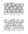
- FIG 1 is a cross-sectional view schematically showing an electrode mixture layer in which second active material particles 2 are packed so as to dose the gaps between first active material particles 1.
- FIG 2 is a cross-sectional view schematically showing an electrode mixture layer in which only first active material particles 1 are packed. In the packed state illustrated in FIG 2 , there are a large amount of gaps between the first active material particles. It is thus thought that the active material is not sufficiently packed.
- FIG. 3 is a cross-sectional view schematically showing an electrode mixture layer in which only second active material particles 2 are packed. In the packed state illustrated in FIG 3 , there are a large amount of gaps due to the influence of the friction resistance between the second active material particles. It is thus thought that the active material is not sufficiently packed.
- FIG. 4 is a cross-sectional view schematically showing an electrode mixture layer in which second active material particles 4 are packed so as to dose the gaps between first active material particles 3 and the first active material particles and the second active material particles are agglomerated primary particles (secondary particles).
- second active material particles 4 are packed so as to dose the gaps between first active material particles 3 and the first active material particles and the second active material particles are agglomerated primary particles (secondary particles).
- the active material is packed as illustrated in FIG 4 , the packed state is good just like the state of FIG. 1 .
- the active material particles include secondary particles, the reaction area increases and electrolyte penetration improves.
- FIG 5 is a cross-sectional view schematically showing an electrode mixture layer in which only first active material particles 3 are packed and the first active material particles 3 are secondary particles.
- the active material is packed as illustrated in FIG 5 , it can also be said that the active material is not sufficiently packed.
- FIG 6 is a cross-sectional view schematically showing an electrode mixture layer in which only primary particle 5, which have been produced by compression, are packed.
- the active material is packed as illustrated in FIG 6 , it can also be said that the active material is not sufficiently packed.
- the electrode for a non-aqueous electrolyte secondary battery can be produced by the method described below.
- An electrode mixture paste containing first active material particles and a binder is prepared.
- the electrode mixture paste is applied onto a current collector surface and dried to form a coating.
- the coating is porous and has a relatively small packing rate.
- the coating is compressed to form an electrode mixture layer. In this way, an electrode for a non-aqueous electrolyte secondary battery can be obtained.
- the first active material particles are partially crushed in the step of compressing the electrode mixture layer. That is, when the coating is compressed, the first active material particles are crushed, so that non-spherical second active material particles are formed. As a result, the second active material particles are efficiently packed so as to close the gaps between the first active material particles, and hence, the packing rate of the electrode mixture layer is significantly improved.
- the packing rate of the electrode mixture layer can be obtained by (true volume of electrode mixture layer)/(apparent volume of electrode mixture layer).
- the true volume of the electrode mixture layer can be determined from the true densities of the active material, conductive agent, binder, and the like contained in the electrode mixture layer and the weight ratios thereof in the electrode mixture.
- the apparent volume of the electrode mixture layer can be calculated from the thickness and area of the electrode mixture layer.
- the packing rate of the electrode mixture layer is a value less than 1. On the assumption that the electrode mixture layer has no gaps, the packing rate is the highest value of 1.
- the packing rate of the electrode mixture layer is, for example, preferably 0.79 or more, and more preferably 0.85 to 0.90.
- the active material particles not be crushed, where possible, before and during the step of applying the electrode mixture paste onto the current collector and drying it to form the coating.
- the active material particles be partially crushed in the step of compressing the coating. That is, it is preferable that the active material particles have: such a mechanical strength that they are not crushed by the stress exerted on the active material particles before and during the step of applying the electrode mixture paste onto the current collector surface and drying it to form the coating; and such a mechanical strength that they are partially crushed to form second active material particles in the step of compressing.
- the mechanical strength of the active material particles refers to compression rupture strength.
- compression rupture strength is measured using particles having a size equal to the D50 (median diameter) of the first active material particles and a circularity of 0.97.
- the compression rupture strength is, for example, 40 to 100 MPa, such particles are unlikely to be crushed before and during the step of forming the coating, and thus 40 to 100 MPa is preferable.
- Compression rupture strength can be measured, for example, with a micro-compression tester MCT-W available from Shimadzu Corporation.
- the method for controlling the mechanical strength of the active material particles is not particularly limited. While the mechanical strength changes with the material, shape, particle size, etc. of the active material particles, the mechanical strength can be controlled, for example, by heating the active material particles. In terms of accurately controlling the mechanical strength of the secondary particles, it is preferable, before the step of preparing the electrode mixture paste, to crush the first active material particles and then heat them for re-agglomeration. Specifically, the first active material particles with a mean particle size of 5 to 20 ⁇ m are crushed and then heated for re-agglomeration. The mean particle size of the agglomerated particles is preferably 5 to 20 ⁇ m.
- the heating conditions are not particularly limited, and can be suitably selected depending on the desired mechanical strength. The heating temperature is, for example, preferably 500 to 800°C.
- the mean particle size of the active material decreases from the mean particle size of the active material before the compression.
- the compressive stress is defined as the amount of change in the mean particle size of the active material.
- the mean particle size of the active material refers to median diameter in the volume basis particle size distribution of the active material.
- the coating is compressed so that the mean particle size D 1 ( ⁇ m) of the active material decreases by 20 to 50% relative to the mean particle size D 0 ( ⁇ m) of the active material before the compression (20 ⁇ (D 0 -D 1 /D 0 ⁇ 100 ⁇ 50). In particular, more preferably 30 ⁇ (D 0 -D 1 )/D 0 ⁇ 100 ⁇ 50, and most preferably 40 ⁇ (D 0 -D 1 )/D 0 ⁇ 100 ⁇ 50.
- the active material may be excessively crushed, and the second active material particles may be formed excessively. Since the second active material particles have a higher friction resistance between the particles than the first active material particles, the packing rate of the electrode mixture layer may not be sufficiently increased.
- the method for controlling the compressive stress is not particularly limited.
- the compression method is preferably compression (rolling) using rollers.
- the compressive stress can be controlled by adjusting the distance between the rollers.
- the mechanical strength of the active material particles is too high relative to the compressive stress, the active material particles resist crushing when compressed.
- the second active material particles are not sufficiently formed, and eventually, almost no second active material particles may be formed, as illustrated in FIG. 2 . It is thus believed that the packing rate of the electrode mixture layer cannot be sufficiently increased, as described above.
- the first active material particles may be primary particles or agglomerated primary particle.
- the second active material particles may also be primary particles or agglomerated primary particles.
- the invention is advantageously applicable to either the positive electrode or negative electrode of a non-aqueous electrolyte secondary battery, it is particularly effective for the positive electrode.
- the non-aqueous electrolyte secondary battery of the invention includes an electrode group, a non-aqueous electrolyte, and a battery case.
- the electrode group includes the above-described electrode for a non-aqueous electrolyte secondary battery, a counter electrode, and a porous insulating layer interposed therebetween.
- other constituent elements than the above-mentioned electrode namely, the counter electrode, the porous insulating layer, the non-aqueous electrolyte, and the battery case, are not particularly limited.
- a lithium ion secondary battery is described in detail as an embodiment of the non-aqueous electrolyte secondary battery according to the invention.
- the non-aqueous electrolyte secondary battery can be produced by the following method. First, a positive electrode and a negative electrode are wound with a porous insulating layer interposed therebetween, to form an electrode group, which is then placed in a battery case. A positive electrode current collector is electrically connected to a positive electrode terminal with a positive electrode lead. A negative electrode current collector is electrically connected to a negative electrode terminal with a negative electrode lead. Thereafter, a non-aqueous electrolyte is injected into a battery case, and the battery case is sealed with a seal plate, to produce a non-aqueous electrolyte secondary battery.
- the shape of the non-aqueous electrolyte secondary battery is not particularly limited.
- a well known structure such as the cylindrical type, the prismatic type, or the sheet type can be employed.
- the positive electrode includes a positive electrode active material capable of absorbing and desorbing lithium ions as an essential component, and includes optional components such as a conductive agent and a binder.
- the positive electrode active material is not particularly limited, and examples include lithium transition metal composite oxides and transition metal polyanion compounds.
- lithium transition metal composite oxides include lithium cobaltate (LiCoO 2 ), modified lithium cobaltate, lithium nickelate (LiNiO 2 ), modified lithium nickelate, lithium manganate (LiMn 2 O 2 ), modified lithium manganate, and such oxides in which Co, Ni or Mn is partially replaced with other transition metal element(s), typical metal(s) such as aluminum, or alkaline earth metal(s) such as magnesium.
- the invention is particularly effective when using nickel lithium composite oxides such as lithium nickelate and modified lithium nickelate.
- the nickel lithium composite oxides are preferably compounds represented by LiNi 1-x MxO 2 where M is at least one selected from Co, Mn, Al, Fe, and Cr. With respect to x, preferably 0 ⁇ x ⁇ 0.5, and more preferably 0.1 ⁇ x ⁇ 0.4.
- transition metal polyanion compounds include phosphoric add compounds having the Nasicon or olivine structure and sulfuric add compounds.
- transition metals include manganese, iron, cobalt, and nickel. These positive electrode active materials can be used singly or in combination of two or more of them.
- the conductive agent is not particularly limited if it is capable of ensuring the electrical conductivity of the positive electrode mixture layer.
- carbon materials such as carbon black, acetylene black, ketjen black, and graphite can be used. These conductive agents can be used singly or in combination of two or more of them.
- the binder is not particularly limited if it is capable of bonding an active material and a conductive agent to the current collector surface.
- examples include polytetrafluoroethylene (PTFE), modified PTFE, polyvinylidene fluoride (PVDF), modified PVDF, fluorine-containing resins such as fluorocarbon rubber, thermoplastic resins such as polypropylene and polyethylene, and modified acrylonitrile rubber particles (e.g., "BM-500B (trade name)" available from Zeon Corporation).
- BM-500B trade name
- thickeners include carboxymethyl cellulose (CMC), polyethylene oxide (PEO), and modified acrylonitrile rubber (e.g., BM-720H (trade name) available from Zeon Corporation).
- the positive electrode is produced, for example, as follows.
- a positive electrode mixture paste is prepared by mixing a positive electrode active material, if necessary, a conductive agent, a binder, and a predetermined solvent.
- the positive electrode mixture paste is applied onto a surface of a current collector and dried to form a coating.
- the coating is then compressed to obtain a positive electrode.
- the solvent can be an organic solvent such as N-methyl-2-pyrrolidone, water, or the like.
- an additive such as a surfactant may be added.
- the positive electrode current collector can be, for example, a foil made of a metal which is stable at the positive electrode potential, such as aluminum, or a film containing a metal on the surface.
- the surface may be roughened or perforated.
- the negative electrode includes a negative electrode active material capable of absorbing and desorbing lithium ions as an essential component, and includes a binder as an optional component.
- the negative electrode active material is not particularly limited and can be a known material.
- Examples include carbon materials such as various natural graphites, various artificial graphites, petroleum coke, carbon fiber, baked organic polymers, carbon nanotubes and carbon nanohoms, oxides, composite materials containing silicon or tin such as silicides, various metals, and alloy materials.
- the binder is not particularly limited, but it is preferable to use rubber particles since they can provide sufficient bonding properties in a small amount.
- rubber particles containing a styrene unit and a butadiene unit examples include styrene-butadiene copolymer (SBR) and modified SBR.
- SBR styrene-butadiene copolymer
- thickeners examples include those containing a water-soluble polymer, and the water-soluble polymer is preferably a cellulose type resin, and CMC is particularly preferable. It is also possible to use PVDF, modified PVDF, or the like as the binder.
- the negative electrode is produced, for example, as follows.
- a negative electrode mixture paste is prepared by mixing a negative electrode active material, if necessary, a binder, and a predetermined solvent.
- the negative electrode mixture paste is applied onto a surface of a current collector and dried to form a coating.
- the coating is then compressed to obtain a negative electrode.
- the solvent is not particularly limited; for example, the same solvents as those listed as positive electrode solvents can be used.
- the negative electrode current collector can be, for example, a foil made of a metal which is stable at the negative electrode potential, such as copper, or a film whose surface has a metal which is stable at the negative electrode potential, such as copper. In terms of further enhancing the current collecting capability of the current collector, the surface may be roughened or perforated.
- the porous insulating layer is not particularly limited; however, it is preferably a micro-porous film or non-woven fabric that is a material capable of withstanding the environment in which the battery is used, allows electrolyte ions to pass through, and is capable of insulating the positive electrode from the negative electrode.
- An example is a micro-porous film made of a polyolefin resin.
- the polyolefin resin can be polyethylene, polypropylene, or the like.
- the micro-porous film may be a mono-layer film made only of one resin, a multi-layer film made of two or more resins, or a multi-layer film made of a resin and an inorganic material such as alumina.
- the non-aqueous electrolyte includes a non-aqueous solvent and a solute dissolved in the non-aqueous solvent.
- the non-aqueous solvent is not particularly limited, and for example, conventional non-aqueous solvents can be used without any particular limitation. Examples include carbonates, halogenated hydrocarbons, ethers, ketones, nitriles, lactones, and oxolane compounds.
- solvent mixtures of a high dielectric constant solvent such as ethylene carbonate (EC) or propylene carbonate (PC) and a low viscosity solvent such as dimethyl carbonate (DMC), diethyl carbonate (DEC), or ethyl methyl carbonate (EMC) are preferred.
- DMC dimethyl carbonate
- DEC diethyl carbonate
- EMC ethyl methyl carbonate
- a sub-solvent such as dimethoxyethane (DME), tetrahydrofuran (THF), or ⁇ -buty
- the non-aqueous electrolyte may contain various additives in order to improve battery characteristics such as storage characteristics, cycle characteristics, and safety.
- additives include vinylene carbonate (VC), cyclohexyl benzene (CHB), and derivatives thereof.
- the solute is not particularly limited, and examples include inorganic salts selected from LiPF 6 , LiBF 4 , LiClO 4 , and LiAsF 6 , derivatives of such inorganic salts, organic salts selected from LiSO 3 CF 3 , LiC(SO 3 CF 3 ) 2 , LiN(SO 3 CF 3 ) 2 , LiN(SO 2 C 2 F 5 ) 2 , and LiN(SO 2 CF 3 )(SO 2 C 4 F 9 ), and derivatives thereof.
- the concentration of the solute in the non-aqueous electrolyte is not particularly limited, and is, for example, 0.5 to 2.0 mol/l.
- the battery case is not particularly limited, and for example, a known suitable material can be used. Examples of materials include aluminum alloys, nickel-plated iron alloys, and laminates of various resins and metals.
- a positive electrode mixture paste was prepared by stirring 3 kg of "Cellseed N (trade name)” (lithium nickelate, LiNiO 2 ) of NIPPON CHEMICAL INDUSTRIAL CO., LTD., serving as first active material particles, 1 kg of "#1320 (trade name)” (NMP solution containing 12% by weight of PVDF) of Kureha Corporation, serving as a positive electrode binder, 90 g of acetylene black, serving as a conductive agent, and a suitable amount of NMP (N-methyl-2-pyrrolidone), serving as a solvent, with a double-arm kneader.
- the first active material particles had a mean particle size (D50) of 11 ⁇ m and an average circularity of 0.97, and particles with a particle size of 11 ⁇ m and a circularity of 0.97 had a compression rupture strength of 77 MPa.
- the positive electrode mixture paste was applied onto both sides of a 15- ⁇ m thick aluminum foil (positive electrode current collector) except for the area to which a positive electrode lead was to be connected, and dried to form a coating.
- the coating was then compressed with rollers, to form positive electrode mixture layers.
- the distance between the two rollers was set to 70 ⁇ m to adjust the compressive stress, so that ⁇ (D 0 -D 1 )/D 0 ⁇ 100 was adjusted to 33%.
- the volume basis particle size distribution of the active material is shown in FIG 7 . Thereafter, the electrode plate was slit to such a width that it was capable of being inserted into a battery case for a cylindrical battery (product number 18650). In this way, a positive electrode hoop was produced.
- the packing rate of the electrode mixture layer was obtained by (true volume of electrode mixture layer)/(apparent volume of electrode mixture layer).
- the true volume of the electrode mixture layer was determined from the true density of each of the positive electrode active material, PVDF, and the conductive agent, and the weight ratios thereof in the positive electrode mixture.
- the apparent volume of the electrode mixture layer was calculated from the thickness and area of the electrode mixture layer.
- FIG 8 shows an SEM of the electrode mixture layer of Example 1.
- a negative electrode mixture paste was prepared by stirring 3 kg of artificial graphite, serving as a negative electrode active material, 75 g of "BM-400B (trade name)" (aqueous dispersion containing 40% by weight of modified styrene-butadiene copolymer) of Zeon Corporation, serving as a negative electrode binder, 30 g of CMC, serving as a thickener, and a suitable amount of water, serving as a solvent, with a double-arm kneader.
- BM-400B trade name
- the negative electrode mixture paste was applied onto both sides of a 10- ⁇ m thick copper foil (negative electrode current collector) except for the area to which a negative electrode lead was to be connected, and dried to form a coating.
- the coating was then compressed with rollers, to form negative electrode mixture layers with an active material layer density (active material weight/electrode mixture layer volume) of 1.4 g/cm 3 .
- the thickness of the electrode plate comprising the copper foil and the electrode mixture layers was adjusted to 180 ⁇ m. Thereafter, the electrode plate was slit to such a width that it was capable of being inserted into the battery case for a cylindrical battery (product number 18650). In this way, a negative electrode hoop was produced.
- a non-aqueous electrolyte was prepared by dissolving a solute at a concentration of 1 mol/l in a non-aqueous solvent comprising a mixture of EC, DMC, and EMC in a volume ratio of 2:3:3. Also, 3 parts by weight of VC was added per 100 parts by weight of the non-aqueous electrolyte.
- a cylindrical battery with a product number of 18650 was produced in the following procedure. First, each of the positive electrode and the negative electrode was cut to a predetermined length. One end of a positive electrode lead was connected to the connecting area for the positive electrode lead, while one end of a negative electrode lead was connected to the connecting area for the negative electrode lead. Thereafter, a porous insulating layer, comprising a 15- ⁇ m thick micro-porous film made of polyethylene resin, was placed between the positive electrode and the negative electrode, and this was wound to form a cylindrical electrode group. The electrode group was sandwiched between an upper insulating ring and a lower insulating ring, and was then placed in the battery case. Subsequently, 5 g of the non-aqueous electrolyte was weighed and injected into the battery case, and the pressure was lowered to 133 Pa to impregnate the electrode group with the non-aqueous electrolyte.
- the other end of the positive electrode lead was welded to the backside of a battery lid.
- the other end of the negative electrode lead was welded to the inner bottom face of the battery case.
- the opening of the battery case was sealed with the battery lid the circumference of which was fitted with an insulating packing, to produce a cylindrical lithium ion secondary battery.
- Each battery was charged and discharged between 3 V and 4.2 V at a constant current of 400 mA at an ambient temperature of 20°C, and the product of discharge time and current value was used as discharge capacity (mAh).
- a lithium ion secondary battery was produced in the same manner as in Example 1 except for the following.
- the first active material particles were heated at a temperature of 750°C in air atmosphere for 50 hours.
- the first active material particles had a mean particle size of 11 ⁇ m and an average circularity of 0.99, and particles with a particle size of 11 ⁇ m and a circularity of 0.97 had a compression rupture strength of 94 MPa.
- the distance between the rollers used for the compression was set to 70 ⁇ m to adjust the compressive stress so that ⁇ (D 0 -D 1 )/D 0 ⁇ 100 was adjusted to 20%.
- a lithium ion secondary battery was produced in the same manner as in Example 2, except that the distance between the rollers used for the compression was set to 20 ⁇ m to adjust the compressive stress so that ⁇ (D 0 -D 1 )/Do ⁇ 100 was adjusted to 40%.
- a lithium ion secondary battery was produced in the same manner as in Example 1 except for the following.
- the primary particles were heated at a temperature of 600°C in air atmosphere for 10 hours, to obtain first active material particles comprising agglomerated primary particles.
- the first active material particles had a mean particle size of 10 ⁇ m and an average circularity of 0.95, and particles with a particle size of 10 ⁇ m and a circularity of 0.97 had a compression rupture strength of 60 MPa.
- the distance between the rollers used for the compression was set to 70 ⁇ m to adjust the compressive stress so that ⁇ (D 0 -D 1 )/D 0 ⁇ 100 was adjusted to 50%.
- a lithium ion secondary battery was produced in the same manner as in Example 4, except that the distance between the rollers used for the compression was set to 120 ⁇ m to adjust the compressive stress so that ⁇ (D 0 -D 1 )/D 0 ⁇ 100 was adjusted to 20%.
- a lithium ion secondary battery was produced in the same manner as in Example 1 except for the following. Using a jet mill "Co-Jet (trade name)" available from Seishin Enterprise Co., Ltd., Cellseed N was crushed until the mean particle size became 3 ⁇ m, to obtain primary particles. The primary particles were heated at a temperature of 750°C in air atmosphere for 50 hours, to obtain first active material particles comprising agglomerated primary particles. The first active material particles had a mean particle size of 11 ⁇ m and an average circularity of 0.96, and particles with a particle size of 11 ⁇ m and a circularity of 0.97 had a compression rupture strength of 68 MPa.
- the distance between the rollers used for the compression was set to 70 ⁇ m to adjust the compressive stress so that ⁇ (D 0 -D 1 )/Do ⁇ 100 was adjusted to 40%. It is noted that the heating temperature was heightened and the heating time was increased. Thus, the primary particles of the first active material particles of Example 6 were sintered more strongly than the first active material particles of Example 4, and the mechanical strength was high.
- a lithium ion secondary battery was produced in the same manner as in Example 1, except that the distance between the rollers used for the compression was set to 20 ⁇ m to adjust the compressive stress so that ⁇ (D 0 -D 1 ⁇ /D 0 ⁇ 100 was adjusted to 60%.
- a lithium ion secondary battery was produced in the same manner as in Example 1, except that the distance between the rollers used for the compression was set to 120 ⁇ m to adjust the compressive stress so that ⁇ (D 0 -D 1 )/D 0 ⁇ 100 was adjusted to 10%.
- a lithium ion secondary battery was produced in the same manner as in Example 1 except for the following.
- the first active material particles were heated at a temperature of 750°C in air atmosphere for 50 hours.
- the first active material particles had a mean particle size of 11 ⁇ m and an average circularity of 0.99, and particles with a particle size of 11 ⁇ m and a circularity of 0.97 had a compression rupture strength of 94 MPa.
- the distance between the rollers used for the compression was set to 120 ⁇ m to adjust the compressive stress so that ⁇ (D 0 -D 1 )/D 0 ⁇ 100 was adjusted to 0% (i.e., the active material particles were not crushed due to the large distance between the rollers).
- a lithium ion secondary battery was produced in the same manner as in Example 4, except that the distance between the rollers used for the compression was set to 20 ⁇ m to adjust the compressive stress so that ⁇ (D 0 -D 1 )/D 0 ⁇ 100 was adjusted to 75%.
- a lithium ion secondary battery was produced in the same manner as in Example 6, except that the distance between the rollers used for the compression was set to 20 ⁇ m to adjust the compressive stress so that ⁇ (D 0 -D 1 )/D 0 ⁇ 100 was adjusted to 70%.
- a lithium ion secondary battery was produced in the same manner as in Example 6, except that the distance between the rollers used for the compression was set to 120 ⁇ m to adjust the compressive stress so that ⁇ (D 0 -D 1 )/D 0 ⁇ 100 was adjusted to 15%.
- a lithium ion secondary battery was produced in the same manner as in Example 1 except for the following. Using a jet mill "court (trade name)" available from Seishin Enterprise Co., Ltd., Cellseed N was crushed until the mean particle size became 3 ⁇ m, to obtain primary particles. These primary particles were used as the positive electrode active material. Further, the distance between the rollers used for the compression was set to 20 ⁇ m to adjust the compressive stress.
- Example 1 The conditions of Examples 1 to 6 and Comparative Examples 1 to 7 are shown in Table 1, and the results are shown in Table 2.
- Table 2 A represents the packed state of active material as illustrated in FIG 4 , B represents the state as illustrated in FIG. 5 , and C represents the state as illustrated in FIG 6 .
- Comparative Example 7 was similar to C since the first active material particles were merely crushed by the jet mill.
- Table 2 shows that the packed state A of active material, i.e., the positive electrode in which the non-spherical second active material particles were packed so as to dose the gaps between the substantially spherical first active material particles, resulted in a high packing rate of the electrode mixture layer. Further, the batteries using such positive electrodes exhibited excellent discharge capacities.
- Example 4 exhibited the highest packing rate of the electrode mixture layer and the highest discharge capacity of the battery. This is probably because the mechanical strength of the active material particles and the compressive stress were controlled favorably.
- the packed state B of active material i.e., the positive electrode in which only the first active material particles were packed
- the packed state C of active material i.e., the positive electrode in which only the second active material particles were packed
- the batteries using such positive electrodes exhibited low discharge capacities.
- an electrode in a preferable packed state i.e., packed state A of active material
- a suitable compressive stress in the step of compressing the electrode, for example, by changing the mechanical strength of the active material particles and the distance between the rollers.
- Comparative Example 2 Comparative Example 3, Comparative Example 6, since the compressive stress was small relative to the mechanical strength of the active material particles, most of the active material particles were not crushed. Probably for this reason, many of the gaps between the active material particles remained, and the packing rate of the electrode mixture layer was low.
- Comparative Example 1 Comparative Example 4, and Comparative Example 5, since the compressive stress was large relative to the mechanical strength of the active material particles, substantially all the active material particles were crushed. At this time, gaps were formed between the second active material particles, and probably for this reason, the packing rate of the electrode mixture layer was low.
- lithium nickelate was used as the positive electrode active material, but the active material is not particularly limited, since the invention is characterized by first active material particles and second active material particles packed so as to dose the gaps between the first active material particles.
- the invention is also effectively applicable to other positive electrode active materials and negative electrode active materials.
- the electrode for a non-aqueous electrolyte secondary battery according to the invention has a higher packing rate of the electrode mixture layer than conventional rates.
- the non-aqueous electrolyte secondary battery including this electrode can have a superior charge/discharge capacity to conventional capacities, and therefore, is useful in the overall applications of non-aqueous electrolyte secondary batteries.
Applications Claiming Priority (2)
| Application Number | Priority Date | Filing Date | Title |
|---|---|---|---|
| JP2008135596A JP2009283354A (ja) | 2008-05-23 | 2008-05-23 | 非水電解質二次電池用電極およびその製造方法ならびに非水電解質二次電池 |
| PCT/JP2009/002177 WO2009141991A1 (ja) | 2008-05-23 | 2009-05-18 | 非水電解質二次電池用電極およびその製造方法ならびに非水電解質二次電池 |
Publications (1)
| Publication Number | Publication Date |
|---|---|
| EP2296207A1 true EP2296207A1 (en) | 2011-03-16 |
Family
ID=41339931
Family Applications (1)
| Application Number | Title | Priority Date | Filing Date |
|---|---|---|---|
| EP09750353A Withdrawn EP2296207A1 (en) | 2008-05-23 | 2009-05-18 | Electrode for non-aqueous electrolyte secondary battery, manufacturing method therefor, and non-aqueous electrolyte secondary battery |
Country Status (5)
| Country | Link |
|---|---|
| US (1) | US20100209763A1 (ja) |
| EP (1) | EP2296207A1 (ja) |
| JP (1) | JP2009283354A (ja) |
| CN (1) | CN101816083B (ja) |
| WO (1) | WO2009141991A1 (ja) |
Families Citing this family (23)
| Publication number | Priority date | Publication date | Assignee | Title |
|---|---|---|---|---|
| JP5439299B2 (ja) * | 2010-07-06 | 2014-03-12 | 株式会社東芝 | 電池用負極活物質、非水電解質電池、電池パック、及び自動車 |
| JP5670671B2 (ja) * | 2010-09-02 | 2015-02-18 | 日立マクセル株式会社 | 電池用正極の製造方法およびリチウムイオン二次電池の製造方法 |
| US20140127585A1 (en) * | 2011-05-26 | 2014-05-08 | National Institute Of Advanced Industrial Science And Technology | Positive electrode active material for nonaqueous electrolyte secondary battery, nonaqueous electrolyte secondary battery, vehicle, and process for producing nonaqueous electrolyte secondary battery positive electrode active material |
| JP5273274B1 (ja) | 2012-04-27 | 2013-08-28 | 東洋インキScホールディングス株式会社 | リチウム二次電池電極形成用組成物、二次電池用電極 |
| WO2014103166A1 (ja) * | 2012-12-27 | 2014-07-03 | 三洋電機株式会社 | 非水電解質二次電池用正極活物質及び非水電解質二次電池 |
| JP6361955B2 (ja) | 2013-01-11 | 2018-07-25 | 株式会社Gsユアサ | 蓄電素子及びその製造方法 |
| JP6369739B2 (ja) | 2013-01-11 | 2018-08-08 | 株式会社Gsユアサ | 蓄電素子及びその製造方法 |
| JP5876850B2 (ja) * | 2013-03-26 | 2016-03-02 | Jx金属株式会社 | リチウムイオン電池用正極活物質、リチウムイオン電池用正極、及び、リチウムイオン電池 |
| JP6017364B2 (ja) * | 2013-03-29 | 2016-10-26 | Jx金属株式会社 | リチウムイオン電池用正極活物質、リチウムイオン電池用正極、及び、リチウムイオン電池 |
| EP3198669B1 (en) * | 2014-09-23 | 2023-10-18 | Jiangsu Hengtron Nanotech Co., Ltd. | Lithium metal oxide containing batteries having improved rate capability |
| US10109854B2 (en) * | 2015-09-30 | 2018-10-23 | Panasonic Corporation | Positive electrode active material for nonaqueous electrolyte secondary batteries and nonaqueous electrolyte secondary battery |
| JP6337360B2 (ja) * | 2016-08-31 | 2018-06-06 | 住友化学株式会社 | リチウム二次電池用正極活物質、リチウム二次電池用正極及びリチウム二次電池 |
| US11121363B2 (en) | 2016-08-31 | 2021-09-14 | Panasonic Intellectual Property Management Co., Ltd. | Positive electrode active material for non-aqueous electrolyte secondary batteries, and non-aqueous electrolyte secondary battery |
| WO2018047843A1 (ja) * | 2016-09-07 | 2018-03-15 | 株式会社Gsユアサ | 蓄電素子及び蓄電素子の製造方法 |
| DE102016217390A1 (de) * | 2016-09-13 | 2018-03-15 | Robert Bosch Gmbh | Elektrode mit lokalen Porositätsunterschieden, Verfahren zur Herstellung einer solchen Elektrode und deren Verwendung |
| KR102053843B1 (ko) * | 2016-11-08 | 2019-12-09 | 주식회사 엘지화학 | 음극 및 상기 음극의 제조방법 |
| WO2019044205A1 (ja) * | 2017-08-31 | 2019-03-07 | パナソニックIpマネジメント株式会社 | 非水電解質二次電池用正極活物質、非水電解質二次電池用正極及び非水電解質二次電池 |
| JP2019175721A (ja) * | 2018-03-29 | 2019-10-10 | 三洋電機株式会社 | 非水電解質二次電池用正極の製造方法及び非水電解質二次電池の製造方法 |
| JP6600734B1 (ja) * | 2018-11-30 | 2019-10-30 | 住友化学株式会社 | リチウム金属複合酸化物粉末、リチウム二次電池用正極活物質、正極、及びリチウム二次電池 |
| JP7456671B2 (ja) * | 2020-03-18 | 2024-03-27 | エルジー・ケム・リミテッド | リチウム二次電池用正極材、これを含む正極及びリチウム二次電池 |
| CN111416116B (zh) * | 2020-03-27 | 2021-06-29 | 宁德新能源科技有限公司 | 正极活性材料及包含其的电化学装置 |
| CN114824439A (zh) * | 2021-03-05 | 2022-07-29 | 宁德新能源科技有限公司 | 电化学装置和电子装置 |
| US20220411277A1 (en) * | 2021-06-29 | 2022-12-29 | Samsung Sdi Co., Ltd. | Positive active material for lithium secondary battery, method of preparing positive active material, positive electrode for lithium secondary battery including positive active material, and lithium secondary battery including positive electrode including positive active material |
Family Cites Families (7)
| Publication number | Priority date | Publication date | Assignee | Title |
|---|---|---|---|---|
| JP2001512407A (ja) * | 1997-02-19 | 2001-08-21 | エイチ・シー・スタルク・ゲゼルシヤフト・ミツト・ベシユレンクテル・ハフツング・ウント・コンパニー・コマンジツトゲゼルシヤフト | リチウム遷移金属化合物を製造する方法 |
| JP2002358966A (ja) * | 2001-06-04 | 2002-12-13 | Hitachi Ltd | リチウム二次電池正極板及びリチウム二次電池 |
| US7413703B2 (en) * | 2003-01-17 | 2008-08-19 | Eveready Battery Company, Inc. | Methods for producing agglomerates of metal powders and articles incorporating the agglomerates |
| WO2004082046A1 (ja) * | 2003-03-14 | 2004-09-23 | Seimi Chemical Co., Ltd. | リチウム二次電池用正極活物質粉末 |
| WO2005020354A1 (ja) * | 2003-08-21 | 2005-03-03 | Seimi Chemical Co., Ltd. | リチウム二次電池用の正極活物質粉末 |
| JP5172089B2 (ja) * | 2005-11-14 | 2013-03-27 | Jfeケミカル株式会社 | リチウムイオン二次電池用負極の製造方法 |
| JP2007335318A (ja) * | 2006-06-16 | 2007-12-27 | Sony Corp | 非水電解質二次電池 |
-
2008
- 2008-05-23 JP JP2008135596A patent/JP2009283354A/ja active Pending
-
2009
- 2009-05-18 WO PCT/JP2009/002177 patent/WO2009141991A1/ja active Application Filing
- 2009-05-18 EP EP09750353A patent/EP2296207A1/en not_active Withdrawn
- 2009-05-18 CN CN2009801006110A patent/CN101816083B/zh not_active Expired - Fee Related
- 2009-05-18 US US12/679,612 patent/US20100209763A1/en not_active Abandoned
Non-Patent Citations (1)
| Title |
|---|
| See references of WO2009141991A1 * |
Also Published As
| Publication number | Publication date |
|---|---|
| JP2009283354A (ja) | 2009-12-03 |
| US20100209763A1 (en) | 2010-08-19 |
| CN101816083B (zh) | 2013-02-06 |
| WO2009141991A1 (ja) | 2009-11-26 |
| CN101816083A (zh) | 2010-08-25 |
Similar Documents
| Publication | Publication Date | Title |
|---|---|---|
| EP2296207A1 (en) | Electrode for non-aqueous electrolyte secondary battery, manufacturing method therefor, and non-aqueous electrolyte secondary battery | |
| EP3588613A1 (en) | Electrochemical device | |
| JP5568886B2 (ja) | 活物質、電池および電極の製造方法 | |
| JP4306697B2 (ja) | 二次電池 | |
| JP4120262B2 (ja) | 非水電解質電池 | |
| WO2015045385A1 (ja) | 非水電解液二次電池用負極、非水電解液二次電池、及び非水電解液二次電池用負極の製造方法 | |
| JP6090247B2 (ja) | 正極活物質、およびリチウムイオン二次電池 | |
| WO2005098997A1 (ja) | 非水電解液二次電池 | |
| JP2015122340A (ja) | リチウム二次電池 | |
| JP2004355824A (ja) | 非水系二次電池用正極活物質および正極 | |
| JP2011192539A (ja) | 非水電解質二次電池用電極およびその製造方法、ならびに非水電解質二次電池 | |
| JP2007273183A (ja) | 負極及び二次電池 | |
| WO2011001666A1 (ja) | 非水電解質二次電池用正極及びその製造方法並びに非水電解質二次電池 | |
| KR102202013B1 (ko) | 전기화학소자용 전극 및 이를 제조하는 방법 | |
| JP2010123331A (ja) | 非水電解質二次電池 | |
| JP2009087885A (ja) | 正極の製造方法 | |
| JP2004134207A (ja) | 正極活物質及び非水電解質二次電池 | |
| JP2002319386A (ja) | 非水電解質二次電池 | |
| WO2010146832A1 (ja) | 非水電解質二次電池用負極の製造方法、負極、およびそれを用いた非水電解質二次電池 | |
| JP2019164967A (ja) | 負極活物質、負極およびリチウムイオン二次電池 | |
| JP4543618B2 (ja) | 非水電解質電池 | |
| JP6981027B2 (ja) | リチウムイオン二次電池用負極活物質、負極及びリチウムイオン二次電池 | |
| JP2002246000A (ja) | 非水電解質二次電池 | |
| JP2009283353A (ja) | 電池用電極およびその製造方法、ならびに電池 | |
| JP2017103139A (ja) | リチウムイオン二次電池用負極活物質、これを用いたリチウムイオン二次電池用負極及びリチウムイオン二次電池 |
Legal Events
| Date | Code | Title | Description |
|---|---|---|---|
| PUAI | Public reference made under article 153(3) epc to a published international application that has entered the european phase |
Free format text: ORIGINAL CODE: 0009012 |
|
| 17P | Request for examination filed |
Effective date: 20100316 |
|
| AK | Designated contracting states |
Kind code of ref document: A1 Designated state(s): AT BE BG CH CY CZ DE DK EE ES FI FR GB GR HR HU IE IS IT LI LT LU LV MC MK MT NL NO PL PT RO SE SI SK TR |
|
| AX | Request for extension of the european patent |
Extension state: AL BA RS |
|
| DAX | Request for extension of the european patent (deleted) | ||
| STAA | Information on the status of an ep patent application or granted ep patent |
Free format text: STATUS: THE APPLICATION HAS BEEN WITHDRAWN |
|
| 18W | Application withdrawn |
Effective date: 20130308 |