EP2287065B1 - Battery holder - Google Patents
Battery holder Download PDFInfo
- Publication number
- EP2287065B1 EP2287065B1 EP10405152A EP10405152A EP2287065B1 EP 2287065 B1 EP2287065 B1 EP 2287065B1 EP 10405152 A EP10405152 A EP 10405152A EP 10405152 A EP10405152 A EP 10405152A EP 2287065 B1 EP2287065 B1 EP 2287065B1
- Authority
- EP
- European Patent Office
- Prior art keywords
- battery holder
- seat tube
- electric bicycle
- battery
- saddle
- Prior art date
- Legal status (The legal status is an assumption and is not a legal conclusion. Google has not performed a legal analysis and makes no representation as to the accuracy of the status listed.)
- Active
Links
- 230000001681 protective effect Effects 0.000 claims description 5
- 238000013461 design Methods 0.000 description 14
- 238000012545 processing Methods 0.000 description 12
- 238000005516 engineering process Methods 0.000 description 7
- 230000006870 function Effects 0.000 description 7
- 229910001416 lithium ion Inorganic materials 0.000 description 7
- 230000002093 peripheral effect Effects 0.000 description 7
- HBBGRARXTFLTSG-UHFFFAOYSA-N Lithium ion Chemical compound [Li+] HBBGRARXTFLTSG-UHFFFAOYSA-N 0.000 description 6
- 230000000694 effects Effects 0.000 description 6
- 230000008901 benefit Effects 0.000 description 5
- 230000005484 gravity Effects 0.000 description 5
- 229910005580 NiCd Inorganic materials 0.000 description 4
- 238000009434 installation Methods 0.000 description 4
- 230000007246 mechanism Effects 0.000 description 4
- 238000000034 method Methods 0.000 description 4
- 238000012544 monitoring process Methods 0.000 description 4
- WHXSMMKQMYFTQS-UHFFFAOYSA-N Lithium Chemical compound [Li] WHXSMMKQMYFTQS-UHFFFAOYSA-N 0.000 description 3
- 229910005813 NiMH Inorganic materials 0.000 description 3
- 230000005540 biological transmission Effects 0.000 description 3
- 238000006073 displacement reaction Methods 0.000 description 3
- 229910052744 lithium Inorganic materials 0.000 description 3
- 230000003446 memory effect Effects 0.000 description 3
- 230000008569 process Effects 0.000 description 3
- XLYOFNOQVPJJNP-UHFFFAOYSA-N water Substances O XLYOFNOQVPJJNP-UHFFFAOYSA-N 0.000 description 3
- 208000027418 Wounds and injury Diseases 0.000 description 2
- 238000013459 approach Methods 0.000 description 2
- 230000006399 behavior Effects 0.000 description 2
- 235000019504 cigarettes Nutrition 0.000 description 2
- 239000000446 fuel Substances 0.000 description 2
- 238000011065 in-situ storage Methods 0.000 description 2
- 150000002500 ions Chemical class 0.000 description 2
- 230000004297 night vision Effects 0.000 description 2
- 229920000642 polymer Polymers 0.000 description 2
- 230000029058 respiratory gaseous exchange Effects 0.000 description 2
- 238000007789 sealing Methods 0.000 description 2
- 241001481833 Coryphaena hippurus Species 0.000 description 1
- UFHFLCQGNIYNRP-UHFFFAOYSA-N Hydrogen Chemical compound [H][H] UFHFLCQGNIYNRP-UHFFFAOYSA-N 0.000 description 1
- CBENFWSGALASAD-UHFFFAOYSA-N Ozone Chemical compound [O-][O+]=O CBENFWSGALASAD-UHFFFAOYSA-N 0.000 description 1
- 230000004913 activation Effects 0.000 description 1
- XAGFODPZIPBFFR-UHFFFAOYSA-N aluminium Chemical compound [Al] XAGFODPZIPBFFR-UHFFFAOYSA-N 0.000 description 1
- 229910052782 aluminium Inorganic materials 0.000 description 1
- 239000004411 aluminium Substances 0.000 description 1
- 230000015572 biosynthetic process Effects 0.000 description 1
- OJIJEKBXJYRIBZ-UHFFFAOYSA-N cadmium nickel Chemical compound [Ni].[Cd] OJIJEKBXJYRIBZ-UHFFFAOYSA-N 0.000 description 1
- 238000006243 chemical reaction Methods 0.000 description 1
- 238000004891 communication Methods 0.000 description 1
- 230000006835 compression Effects 0.000 description 1
- 238000007906 compression Methods 0.000 description 1
- 238000001816 cooling Methods 0.000 description 1
- 230000008878 coupling Effects 0.000 description 1
- 238000010168 coupling process Methods 0.000 description 1
- 238000005859 coupling reaction Methods 0.000 description 1
- 230000006378 damage Effects 0.000 description 1
- 230000007423 decrease Effects 0.000 description 1
- 230000001419 dependent effect Effects 0.000 description 1
- 230000004069 differentiation Effects 0.000 description 1
- 238000007599 discharging Methods 0.000 description 1
- 230000014509 gene expression Effects 0.000 description 1
- 229910052739 hydrogen Inorganic materials 0.000 description 1
- 239000001257 hydrogen Substances 0.000 description 1
- 208000014674 injury Diseases 0.000 description 1
- 238000003780 insertion Methods 0.000 description 1
- 230000037431 insertion Effects 0.000 description 1
- 230000010354 integration Effects 0.000 description 1
- 230000003993 interaction Effects 0.000 description 1
- RVPVRDXYQKGNMQ-UHFFFAOYSA-N lead(2+) Chemical compound [Pb+2] RVPVRDXYQKGNMQ-UHFFFAOYSA-N 0.000 description 1
- GELKBWJHTRAYNV-UHFFFAOYSA-K lithium iron phosphate Chemical compound [Li+].[Fe+2].[O-]P([O-])([O-])=O GELKBWJHTRAYNV-UHFFFAOYSA-K 0.000 description 1
- 230000033001 locomotion Effects 0.000 description 1
- 238000004519 manufacturing process Methods 0.000 description 1
- 239000000463 material Substances 0.000 description 1
- 229910052987 metal hydride Inorganic materials 0.000 description 1
- 239000000203 mixture Substances 0.000 description 1
- 238000003032 molecular docking Methods 0.000 description 1
- 238000013021 overheating Methods 0.000 description 1
- 230000000149 penetrating effect Effects 0.000 description 1
- 238000003825 pressing Methods 0.000 description 1
- 238000007493 shaping process Methods 0.000 description 1
- 229910001220 stainless steel Inorganic materials 0.000 description 1
- 239000010935 stainless steel Substances 0.000 description 1
- 239000000126 substance Substances 0.000 description 1
- 238000012546 transfer Methods 0.000 description 1
Images


Classifications
-
- B—PERFORMING OPERATIONS; TRANSPORTING
- B62—LAND VEHICLES FOR TRAVELLING OTHERWISE THAN ON RAILS
- B62K—CYCLES; CYCLE FRAMES; CYCLE STEERING DEVICES; RIDER-OPERATED TERMINAL CONTROLS SPECIALLY ADAPTED FOR CYCLES; CYCLE AXLE SUSPENSIONS; CYCLE SIDE-CARS, FORECARS, OR THE LIKE
- B62K19/00—Cycle frames
- B62K19/30—Frame parts shaped to receive other cycle parts or accessories
-
- B—PERFORMING OPERATIONS; TRANSPORTING
- B62—LAND VEHICLES FOR TRAVELLING OTHERWISE THAN ON RAILS
- B62H—CYCLE STANDS; SUPPORTS OR HOLDERS FOR PARKING OR STORING CYCLES; APPLIANCES PREVENTING OR INDICATING UNAUTHORIZED USE OR THEFT OF CYCLES; LOCKS INTEGRAL WITH CYCLES; DEVICES FOR LEARNING TO RIDE CYCLES
- B62H5/00—Appliances preventing or indicating unauthorised use or theft of cycles; Locks integral with cycles
- B62H5/001—Preventing theft of parts or accessories used on cycles, e.g. lamp, dynamo
-
- B—PERFORMING OPERATIONS; TRANSPORTING
- B62—LAND VEHICLES FOR TRAVELLING OTHERWISE THAN ON RAILS
- B62K—CYCLES; CYCLE FRAMES; CYCLE STEERING DEVICES; RIDER-OPERATED TERMINAL CONTROLS SPECIALLY ADAPTED FOR CYCLES; CYCLE AXLE SUSPENSIONS; CYCLE SIDE-CARS, FORECARS, OR THE LIKE
- B62K19/00—Cycle frames
- B62K19/30—Frame parts shaped to receive other cycle parts or accessories
- B62K19/36—Frame parts shaped to receive other cycle parts or accessories for attaching saddle pillars, e.g. adjustable during ride
-
- B—PERFORMING OPERATIONS; TRANSPORTING
- B62—LAND VEHICLES FOR TRAVELLING OTHERWISE THAN ON RAILS
- B62K—CYCLES; CYCLE FRAMES; CYCLE STEERING DEVICES; RIDER-OPERATED TERMINAL CONTROLS SPECIALLY ADAPTED FOR CYCLES; CYCLE AXLE SUSPENSIONS; CYCLE SIDE-CARS, FORECARS, OR THE LIKE
- B62K19/00—Cycle frames
- B62K19/30—Frame parts shaped to receive other cycle parts or accessories
- B62K19/40—Frame parts shaped to receive other cycle parts or accessories for attaching accessories, e.g. article carriers, lamps
-
- B—PERFORMING OPERATIONS; TRANSPORTING
- B62—LAND VEHICLES FOR TRAVELLING OTHERWISE THAN ON RAILS
- B62M—RIDER PROPULSION OF WHEELED VEHICLES OR SLEDGES; POWERED PROPULSION OF SLEDGES OR SINGLE-TRACK CYCLES; TRANSMISSIONS SPECIALLY ADAPTED FOR SUCH VEHICLES
- B62M6/00—Rider propulsion of wheeled vehicles with additional source of power, e.g. combustion engine or electric motor
- B62M6/80—Accessories, e.g. power sources; Arrangements thereof
- B62M6/90—Batteries
Definitions
- An electric bicycle differs from a customary bicycle in having an additional electric motor, a sensor for sensing pedalling parameters, control electronics for the electric motor, and a battery or an accumulator.
- the electric motor may be embodied as a wheel hub motor for directly driving the front wheel or rear wheel.
- the electric motor drives a chain or a toothed belt of one of the wheels via a gear mechanism.
- a hub motor on the front or rear wheel, a crankshaft motor as an additional force acting on the foot pedal or an electric motor on a trailer or push-type trailer (exotic design) - are used as force application points of the electric motor.
- the sensor for sensing pedalling parameters is usually installed on the bottom bracket, and monitors, for example, the pedalling frequency or the force supplied by the driver during pedalling, which force acts as torque on the foot pedal shaft.
- the control electronics for the electric motor control the power of the electric motor according to the driver's request and the sensed pedalling parameters.
- setting possibilities such as an infinitely variable pedalling force assistance means, or a desired pedalling force assistance means which is divided into stepped-down stages, which are processed together with the pedalling parameters, are provided (for example a rotary handle), wherein the power of the electric motor is controlled.
- Further functions can be integrated such as, for example, voltage monitoring of the battery or of the accumulator, temperature monitoring, power monitoring or rotational speed monitoring of the motor.
- the battery or the accumulator will be referred to below as the accumulator. It is known to arrange the accumulator between the seat pipe and rear wheel (Flyer/Biketec), in a U shape around the seat pipe, in the lower pipe with an access door (Thömus, Kalkhoff, KogaMyiata), integrated into the luggage rack (WattWorld), integrated into the frame triangle (Dolphin), instead of the water bottle (BionX) or stowed on the bicycle in a handlebar pocket.
- the accumulator can be removed from the bicycle in order to charge it. Holder devices for fastening the accumulator to the provided location on the electric bicycle in a removable fashion are known. A charging process for the accumulator can therefore be carried out, for example, overnight in a charging station.
- lithium polymer accumulators which permit relatively high energy contents with the same weight, will be available.
- the reliability and durability of lithium accumulators has been proven in practice.
- the chemical composition and the quality of the electronics are decisive for reliability.
- Lithium ion accumulators may react very strongly in particular in the event of a short circuit or overvoltage. This has already led to product recalls in the case of laptops.
- NiCd accumulators Manufacturers which equip their electric bicycles with NiCd accumulators also generally supply a power pack which completely discharges the NiCd accumulator before the actual charging process, in order to reduce the memory effect.
- NiMH accumulators have a substantially smaller memory effect. Said effect is avoided altogether in lithium ion accumulators.
- Lithium-iron-phosphate accumulators which have significantly longer service lives than the currently preferably used lithium ion accumulators, are also very promising. Their use could significantly reduce the running costs due to accumulator wear. At present, they are not yet available on a series-production basis in most electric bicycle models.
- a bicycle with limited or restricted pedalling assistance is referred to in Germany as Pedelec, but the expressions E-Bike, Elektrorad or Elektrovelo are also used.
- the term limited pedalling assistance means that the electric motor is switched on when the pedals are operated. The electric motor therefore merely assists, and does this only for as long as the vehicle has not exceeded a speed of 25 km/h. EU guidelines limit the average power of the motor to 250 W. E-Bikes with speed limitation permit locomotion without having to make a large effort.
- the means of transportation referred to here is officially considered to be a bicycle. In Switzerland, it has to be insured as a bicycle; wearing a helmet is recommended but not prescribed.
- Electric bicycles have a range which is restricted by the charge capacity of the accumulator. This charge capacity becomes shorter the steeper the profile of the route. It is not possible to "fill up the tank” again within a few minutes as in a petrol-operated vehicle, but rather a recharging cycle takes several hours, depending on the model. However, in contrast to motorcycles, electric bicycles accelerate quietly and do not make any local contribution to the formation of ozone and smog.
- US 5,618,052 presents a saddle pillar, to whose end a bicycle saddle is fastened.
- the saddle pillar can be inserted into a conventional seat tube of a bicycle.
- a power supply unit with a battery is arranged in the saddle pillar.
- a dynamo unit, in particular a rear light, which is attached to the bicycle saddle, can be supplied with electrical energy using the power supply unit.
- JP 10 053178 which shows the preamble of claim 1, presents a saddle of a motorcycle which is rotatably mounted on the seat tube of the frame.
- a battery holder is provided in the seat tube.
- a cover is provided for covering an opening which is configured to accommodate the battery holder in a removable fashion.
- the bicycle saddle is attached to the cover.
- a plurality of battery cells are arranged in the battery holder.
- US 7,393,125 presents a power supply unit with a battery arranged therein.
- the seat tube of a bicycle frame has, over essentially its entire length, an opening into which the power supply unit can be inserted laterally and secured.
- the battery is configured to supply the electric motor of an electric bicycle with power.
- JP 2000 272567 presents a bicycle with an auxiliary motor.
- a battery is arranged in an upper frame tube in a removable fashion.
- the upper frame tube can be closed off by a flap.
- the saddle is attached to the flap. The battery can easily be inserted into the upper frame tube and removed again, while the height of the saddle can be freely adjusted.
- the object of the present invention is to provide an electric bicycle with a battery holder which can be easily mounted on the electric bicycle and removed without aesthetic disadvantages or considerable aesthetic disadvantages having to be accepted in terms of the design of the electric bicycle.
- the battery holder is to be used, together with a battery/accumulator provided therein, not only for feeding the electric motor and, if appropriate, other electrical loads of the electric bicycle such as, for example, the bicycle lamp, but also as a mobile energy source with various additional functions when it has been released from the electric bicycle.
- the battery holder with the battery or the accumulator arranged therein can therefore easily be inserted from above, together with the bicycle saddle, into the seat tube and secured, if appropriate.
- the bicycle saddle is therefore connected to the battery holder and not directly to the frame, and forces from a person sitting on the saddle are transmitted from the bicycle saddle to the battery holder and the seat tube via the saddle pillar.
- the seat tube can be used in an optimum way as a single open tube for the frame of the electric bicycle for fastening the battery holder and the battery or accumulator arranged therein. This does not require any complex fastening mechanisms. There is no need for any tubes to be weakened by additional opening holes.
- the bicycle saddle is removed from the bicycle together with the battery holder. This prevents theft of the bicycle saddle or of the battery. It is not attractive to steal the bicycle without a saddle, and it is therefore rather improbable. Taking the electric bicycle without its saddle will attract attention (for example of the police) and imply that it has been stolen. Social control is therefore present. This signifies increased protection against theft compared to conventional systems.
- the saddle Since the saddle is removed together with the battery holder, the saddle is prevented from becoming soaked in rain.
- the battery holder comes to rest at a defined position within the seat tube. This permits a lock which engages over multiple components to be installed (quick-action fastener/battery holder and quick-action fastener/tube cover).
- a lowerable, hydraulic saddle pillar can advantageously be used as the saddle pillar.
- the saddle pillar can very easily be set to the lowest position, which reduces the packed dimensions, for transportation.
- the saddle pillar in turn can be very easily set to the preferred riding position without renewed vertical adjustment being necessary.
- the defined position of the battery holder permits a simple structure of the power collector. It is not necessary to run cables in the tube in a movable fashion. A lateral power collection by means of a rail and spring is not necessary either. Advantages are therefore obtained in respect of the resistance against influences of the weather, in terms of the seal and in terms of wear.
- the circuit is made possible only when the pillar is completely fully sprung, giving rise to improved safety.
- the structure of the frame is not weakened.
- a low centre of gravity of the bicycle together with small packed dimensions of the battery holder seat unit are possible.
- a relatively large cross-sectional area provides, in particular, space for a battery or an accumulator with a relatively large capacity. This space is provided by a correspondingly configured seat tube, while an aesthetically pleasing selection can be made for the shape of the cross-sectional area.
- the saddle pillar is arranged in a fixed fashion with respect to the battery holder.
- the setting of the height of the bicycle saddle has to be carried out by correspondingly displacing the battery holder in the seat tube, as a result of which the centre of gravity is also displaced. Since the weight of batteries arranged in the battery holder makes up a significant portion of the weight of the electric bicycle, such displacement of the centre of gravity can have a disadvantageous effect on the riding behaviour of the electric bicycle.
- the battery holder preferably has a substantially oval cross-sectional face or a cross-sectional face which is composed of a plurality of oval, straight or round segments, and the saddle pillar has a substantially round cross-sectional face, wherein the saddle pillar is guided so as to be displaceable in a round or oval tube which is attached to the battery holder, and said saddle pillar can be locked to a quick-action closure.
- a pull-out strap is preferably arranged on the battery holder.
- the strap can be arranged, for example, in the abovementioned round tube for accommodating the saddle pillar and can be automatically pulled back into the round tube or pushed manually into the tube after use by means of a return mechanism such as a spring-loaded device.
- the strap can also be wound, for example, onto a roller, similar to a car seat belt, and pulled out of the battery holder. It is therefore possible for a user of the electric bicycle to park it in a bike park, to remove the battery holder together with the bicycle saddle and to conveniently carry it along by the strap, that is to say for example hang it over his shoulder. This ensures that the battery holder with the battery or accumulator arranged therein becomes a personal object which can be conveniently carried along.
- the battery holder can be additionally further developed in order to improve further its appeal as a personal object.
- a power connection can be configured to supply power to a laptop/PC/Mac, emergency equipment, breathing equipment, radio devices, night vision devices, loudspeakers/amplifiers, a mobile phone charging device or a music player.
- the power connection can also be used as a cigarette lighter socket or as a USB (Universal Serial Bus) socket for these purposes.
- a central processing unit can be provided as a computer module.
- Central processing unit is used in information technology to denote the part of a computer system which monitors and controls the other parts.
- the term central processing unit is used as a means of forming a delineation from peripherals.
- the meaning is heavily dependent on the particular context: for example, whether a single microchip or an entire PC is considered to be a central processing unit depends on the granularity with which the system is considered.
- the term is typically used for the following systems, depending on the context:
- central processing unit is defined according to point 2.
- the following techniques and standards are used as hardware interfaces: USB, USB2, Firewire, Bluetooth, Netzwerk, Audio (Jack, Minijack, Cinch), Multimediabuchse, EIA-232, PCI-bus, SCSI, Funk, card-reading device for credit cards and bank cards and post office cards.
- the peripheral is a component or a device which is located outside the central processing unit of a computer. It is possible to differentiate in a simplified fashion between (internal) peripherals which are installed in the computer and (external) peripherals which are connected thereto by a cable (or else by infrared technology or radio technology).
- Peripherals are used to input and output data or commands into the central processing unit. They provide a "service" for the user and said service can then either take place in a visible fashion (for example paper printout) or invisibly (for example signal conversion of internal modems).
- peripherals graphics card, network card, sound card, main memory, chip set, display/monitor, touch screen display, hard disk, keyboard, microphone, trackball, webcam, touchscreen, touchpad, Bluetooth interfaces or infrared interfaces, loudspeaker, power pack, modem, memory card reading device, mobile phone functions such as SMS/MMS transmission and reception.
- An audio player can be provided for playing MP3 files or podcasts.
- Components can be provided for carrying out standard programs.
- GPS Global Positioning System
- a direction indicator with an arrow can be arranged in a removable fashion on the battery holder.
- the direction indicator can comprise means for mounting the latter on the handlebars or front part of the electric bicycle, and in this context communication between the direction indicator and electronic components of the battery holder can take place via a wireless interface.
- Such a direction indicator can be used to communicate with the rider during a sightseeing tour, during a guided tour through an area or when riding with the electric bicycle.
- An alarm system can be installed in the battery holder.
- a quick-action closure for securing the battery holder can be attached to a seat tube for accommodating an abovementioned battery holder.
- the mounting of the battery holder on the electric bicycle, and removal therefrom, can be additionally simplified with the quick-action closure.
- Opposing contacts for forming an electrical connection between the power connection of the battery holder and electrical components such as, in particular, the motor of the electric bicycle are preferably attached in the seat tube.
- the opposing contacts can be provided in a lower region of the seat tube where it is well protected and an electrical connection of the battery holder or of the battery or accumulator arranged therein can only be made when the battery holder is virtually completely inserted.
- power can be transmitted to two longitudinal rails which are arranged in the seat tube and have corresponding power collectors arranged on the battery holder.
- a cover is preferably displaceably guided in the seat tube, so that the tube opening in the seat tube is closed off in a weatherproof fashion when the battery holder is removed.
- a helical spring or a pneumatic pressure spring is installed under the cover and connected thereto.
- the spring is located above the bottom bracket in the frame.
- a sliding guide can be provided as a guide for the battery holder and termination of the seat tube in the tube opening.
- a coupling to one of the hydraulic or pneumatic systems of a spring-action fork, spring-action leg, brake or tyre is possible.
- the provision of a seal against the ingress of rain water is made possible at the contact point.
- On the upper side of the cover there is a positioning knob. This ensures precise fitting of the battery holder when it is inserted into the seat tube.
- On the upper side of the cover or on the positioning knob there are electrical contact points for the transmission of power.
- On the underside of the battery holder there are corresponding electrical contact opposing elements. In an inner region of the cover, the electric current is conducted from the upper side to the lower side or to the side faces.
- a direct connection routed via wires, from the cover to the motor.
- contact faces are located in the lower region of the seat tube, which contact faces bring about the contact through the cover to the battery holder when the battery holder is completely inserted.
- the circuit is not made possible until the battery holder is completely installed, which provides additional safety.
- An accumulator which is arranged in the battery holder can be charged by means of a charging station in the removed state of the battery holder. It is also possible to charge the accumulator in the installed state by means of a low voltage connection (external to the transformer).
- the transformer is integrated directly into the battery holder.
- the charge station may be of a simple design (one plug-in position) or of multiple design (approximately 5-30 plug-in positions), and they are made available, for example at the entrance to large stores. While the person is, for example, in a large store or a restaurant etc., the battery can be charged for the payment of a fee or as a free service.
- a closure device key, pin, badge, numerical lock, electronic lock
- a corresponding plug and an element corresponding to the closure device are provided on the battery holder.
- a protective projection is preferably provided on the quick-action closure so that, when the battery holder is removed, the electrical contact points which are attached to the cover are protected against influences of the weather.
- a connection which is protected, in particular protected against theft, between the seat tube and the battery holder can preferably be produced with a closing device.
- the battery holder which the user carries with him, can be mounted in a free-standing electric bicycle, as a result of which said bicycle at the destination is available for use.
- the personal data of the user are stored, for example, in electronic components which are made on the battery holder, and said data are transferred automatically, for example, to the operator of the parking station when the battery holder is inserted, after which a lock for securing the electric bicycle in the parking station is opened.
- the duration of use of the electric bicycle can be recorded automatically. It is therefore possible for the electric bicycle to be deposited again at another parking station in the town, which saves costs and makes the electric bicycle available again to other users.
- the services corresponding to the period of use can be billed on a monthly basis, for example.
- the commuter can also use the battery holder with a saddle as a seat at any time; for example when waiting on a platform or for sitting in overfilled trains. Elderly people and fishermen would appreciate this function.
- the situation of a tourist (with personal battery/with rented battery): a tourist who is visiting an unfamiliar city is not in possession of a personal battery holder. This can be rented at the tourist information centre, for example against the presentation of his credit card details.
- the tourist's personal data can be stored electronically by the personnel for the hire period in the battery holder. The tourist can then get to know the town and use electric bicycles as he desires and deposit them again at suitable parking stations. The overall period of use can be in turn recorded and billed when the battery holder is returned. Since the tourist does not know his way about in an unfamiliar town, there is a selection of programmed sightseeing tours.
- the tourist is then directed from location to location through the town by means of, for example, a radio headset, a direction display on the bicycle or signal indicators in the handlebar grips.
- a radio headset for example, a radio headset, a direction display on the bicycle or signal indicators in the handlebar grips.
- an integrated GPS is provided so that the respective location of the tourist is known to the sightseeing system.
- the tourist can also move about freely in the town with the electric bicycle and listen, from time to time, to specific information about local features corresponding to his preselected preferences. This can also take place in conjunction with GPS technology or by means of locally provided signal generators (for example in information pillars) which call and play back the corresponding information on a data memory of the battery holder. If a tourist is already in possession of his own personal battery holder, he can also dispense with the visit to the tourist information centre with the aim of getting to know an unfamiliar town and he can load the route guide and the corresponding audio data directly onto the battery holder at home as a podcast from the Internet.
- the system provides the possibility of a new source of advertising. The system can therefore, for example, describe the direct route to a specific business or restaurant.
- a tourist can also make tours through entire countries (provided that all the existing parking stations have corresponding electric bicycles). To do this, at a starting point he rents a battery holder which is personalized. He then travels along his selected route. This route can also be interrupted, for example, by train journeys or boat journeys. The electric bicycle would then be left at a respectively corresponding parking station and only the battery holder would be taken along. At another railway station or docking point he would then pick up a new electric bicycle and carry on his journey.
- Personal profiles relating to the personalized battery holders can also be stored by the users on an Internet page. Users can contact one another via the web page. The page supports all the criteria which promote interaction between the users.
- the degree of publication of the profiles which are created can be defined. If two users approach one another on a road up to a specified distance the user profiles or parts thereof or other messages can then be replaced according to a predefinable schedule. It is, for example, also possible to transfer personal data if a user approaches a geographically defined location up to a certain distance.
- the situation of the police on an electric bicycle the police patrolman on an electric bicycle has the possibility of using the battery holder to make contact with the police station, for example by radio. Data stored in the battery holder can be called in situ. Further devices which require current have a relatively long service life with the large-capacity battery or accumulator which is arranged in the battery holder.
- a military situation similar to the police, military personnel have an increased electrical energy requirement for certain devices, for example radio devices or night vision devices. This requirement is covered with the large-capacity battery or accumulator which is arranged in the battery holder.
- emergency doctors similar to the police, emergency doctors have an increased electrical energy requirement for certain devices, for example breathing equipment. This requirement is covered with the large-capacity battery or accumulator which is arranged in the battery holder.
- the situation of working in a natural setting the user can ride with the electric bicycle into a recreation area and make use of an increased energy capacity for his electronic equipment in situ in a natural setting.
- the battery holder has a low-voltages connection, for example corresponding to a cigarette lighter in a car.
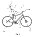
- Figure 1 is a schematic view of an electric bicycle 1 with a front wheel 1.1, a rear wheel 1.2, a frame 1.3 with a seat tube 2 and handlebars 1.4.
- the front wheel 1.1 is connected via the front fork to the handlebars 1.4 which are arranged on the frame 1.3.
- the rear wheel 1.2 is connected via the rear structure to the frame 1.3.
- the design of such an electric bicycle is known in the prior art and also comprises, in particular, a pedal device, brakes and an electric motor. More details will not be given on these devices at this point.
- a battery holder 3 is configured to be inserted into the seat tube 2 and pulled out. The battery holder 3 is shown in the pulled-out state in Figure 1 .
- the battery holder 3 is connected to a saddle pillar 4, to which a bicycle saddle 5 is attached.
- the saddle pillar 4 and the bicycle saddle 5 may be commercially available components.
- a quick-action closure 2.1 for securing the battery holder 3 in the inserted state is attached to the seat tube 2.
- a quick-action closure 3.1 for fastening the saddle pillar 4 to the battery holder 3 or permitting the saddle pillar 4 to be displaced with respect to the battery holder 3 is also attached to the battery holder 3.
- the quick-action closure 3.1 of the battery holder 3 can be integrated into the cover of the battery holder 3 or a commercially available quick-action fastener can be used.
- the battery holder 3 is manufactured, for example, from aluminium, from stainless steel, from a dimensionally stable plastic or from some other dimensionally stable material and has an interior space for accommodating batteries and/or accumulators with a capacity which is necessary for the operation of the electric bicycle. For this purpose, subdivisions and/or holders may be provided in the interior space in the battery holder 3. Cooling devices, such as for example ducts or ribs for suitable air circulation in order to avoid overheating of the batteries or of the accumulators, can be provided in the interior space or on the outside.
- sliding devices such as, for example, a collar 3.4 so that the smallest possible sliding resistance occurs when the battery holder 3 is pushed in and pulled out, and so that the surface of the battery holder is not scratched by the pushing in and pulling out.
- the sliding devices can be attached to the battery holder 3 and/or to the seat tube 2.
- Figure 2 is a schematic view of a detail of the battery holder 3 and the seat tube 2.
- a quick-action closure 2.1 is attached to the tube opening in the seat tube 2.
- the tube opening is closed off by a cover 2.9 which is displaceably guided in the seat tube 2 and is pushed into the seat tube 2 by the battery holder 3 during the pushing-in process.
- the quick-action closure 2.1 of the seat tube 2 has a lock 2.2 which can be connected to the corresponding lock component 3.2 of the battery holder 3 so that the battery holder 3 can be secured against theft in the pushed-in state.
- the cover 2.9 has a positioning knob 2.91 which engages in a corresponding depression in the battery holder 3. As a result, a defined relatively position is provided between the battery holder 3 and the cover 2.9.
- the cover 2.9 also has electrical contact points 2.92 which form an electrical contact with opposing contact points of the battery holder 3.
- a protective projection 2.3 for protecting the electric contact points 2.92 in particular against influences of the weather such as rain or snow when the battery holder 3 is removed and the quick-action closure 2.1 is closed is provided on the operator lever of the quick-action closure 2.1 of the seat tube 2.
- the battery holder has, on an upper side, a charge state display 3.3 which displays, for example, after activation by a switch (not shown), the charge state of the batteries or accumulators arranged in the battery holder.
- a charge plug socket 3.31 for forming an electrical connection to a charge station and charging an accumulator arranged in the battery holder 3 is provided on an upper side of the battery holder.
- a collar 3.4 which is manufactured, for example, from a slidable plastic and ensures easy displacement of the battery holder 3 with respect to the seat tube 2, is provided at the upper end of the battery holder 3. Further collars may be provided at further locations such as, for example, the lower end of the battery holder 3.
- the cover and/or the floor of the battery holder 3 are secured with screws 3.5, with the interior space of the battery holder being sealed in a weather-proof fashion.
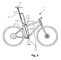
- Figure 3 is a schematic view of a telescopic rod 2.97 which is arranged in the seat tube 2.
- the telescopic rod 2.97 is anchored on one side in a lower region of the seat tube 2 in the frame 1.3 of the electric bicycle 1.
- the telescopic rod 2.97 is connected to the cover 2.9.
- the telescopic rod serves as a guide with a compression spring so that the cover 2.9 is pressed upward, and the tube opening in the seat tube 2 is therefore closed.
- the maximum travel of the cover 2.9 or the highest position at the upper end of the seat tube can be defined by means of the telescopic rod so that the cover 2.9 comes to rest at the level of the tube opening in the seat tube 2 when the battery holder is removed.
- seals may be provided in the region of the opening in the tube, with a suitable spring force giving rise to a seal between the seat tube 2 and the cover 2.9.
- a seal of this type for example is formed, with a collar provided at the upper end of the seat tube 2. If such a collar is not provided on the seat tube 2 but rather on the battery holder 3, the seal is achieved by closing the quick-action closure and the associated clamping effect on the cover 2.9.
- the battery holder 3 has a battery space 3.7 and a saddle pillar space 3.8.
- the saddle pillar space 3.8 may be formed by a cylindrical tube.
- the battery space 3.7 may be substantially round, oval or have a cross-sectional face which is composed of a plurality of oval, straight or round segments and is triangular, rectangular or polygonal or defined by a spline, with part of this cross-sectional face being covered by the cross-sectional face of the saddle pillar space 3.8.
- the description of the cross-sectional face of the battery holder 3 and of the saddle pillar space 3.8 follows the following criteria: - easy subsequent working of an extruded profile, which is used if appropriate; - optimum use of space in terms of the usable battery space; - good ergonomy with minimum impact risks and injury risks when riding or getting onto the bicycle; - streamlined shape; - the possibility of installing electrical or electronic components in defined areas (which have a contour which is as flat as possible); - a good clamping effect or transmission of force by the quick-action closure of the seat tube 2; - the possibility of engaging around the battery holder in a way which is optimum in terms of ergonomy during removal and installation and for transportation; - the possibility of being able to carry the battery holder 3 by means of a strap in a way which is optimum in terms of ergonomy, for example around the person's shoulder or on their back; - a cover face of the battery holder which can be used well and seen well during travel or in the
- Figure 4 shows a battery holder 3 which is pushed completely into the seat tube 2.
- the quick-action fastener 2.1 of the seat tube 2 is closed.
- the lock 2.2 is, for example, in a closed state so that the quick-action fastener 2.1 cannot be opened and the battery holder 3 is arranged protected against theft in the seat tube 2.
- the protective projection 2.3 of the quick-action fastener 2.1 covers an area of an upper cover of the battery holder 3, with additional securing means being formed before the battery holder 3 is pulled out.
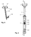
- Figure 5 shows the telescopic rod 2.97 which is connected to the cover 2.9.
- This arrangement is provided in a seat tube 2 (not shown), with opposing contacts 2.98, with which electrical contact is formed between contact points 2.92 of the cover 2.9 as soon as the cover 2.9 is pressed to the level of the opposing contacts 2.9 by the battery holder 3, are mounted at a lower end of the seat tube.
- the opposing contacts 2.9 are connected via lines to the control electronics and/or to the electric motor of the electric bicycle 1.
- the cover 2.9 may comprise a corresponding lock component 2.93 so that when the battery holder 3 is removed the cover 2.9 can be secured in the upper position and therefore protected against pressing in in the event of vandalism.
- Figure 6 shows the front view of the battery holder 3 with the saddle pillar 4, the bicycle saddle 5 and the quick-action fastener 3.1.
- Electrical and/or electronic components 3.61, 3.62, 3.63, 3.64 such as data interfaces or energy supply interfaces, operator control elements, displays, loudspeakers, lights or any other components, are located on the front side.
- the electrical and/or electronic components 3.61, 3.62, 3.63, 3.64 are provided on the front side in Figure 6 by way of example. Of course, they can be arranged at any other location on the surface of the battery holder 3 or even entirely or partially inside the battery holder 3.
- a battery holder with a bicycle saddle which provides new possibilities for the shaping and the design of an electric bicycle and can be easily removed from the electric bicycle, as well as permitting simple handling and improving protection against theft.
Priority Applications (2)
| Application Number | Priority Date | Filing Date | Title |
|---|---|---|---|
| PL10405152T PL2287065T3 (pl) | 2009-08-20 | 2010-08-19 | Uchwyt baterii |
| EP13000087.0A EP2581296A1 (en) | 2009-08-20 | 2010-08-19 | Electric bicycle |
Applications Claiming Priority (1)
| Application Number | Priority Date | Filing Date | Title |
|---|---|---|---|
| CH01291/09A CH701675B1 (de) | 2009-08-20 | 2009-08-20 | Batteriehalterung. |
Related Child Applications (1)
| Application Number | Title | Priority Date | Filing Date |
|---|---|---|---|
| EP13000087.0 Division-Into | 2013-01-09 |
Publications (2)
| Publication Number | Publication Date |
|---|---|
| EP2287065A1 EP2287065A1 (en) | 2011-02-23 |
| EP2287065B1 true EP2287065B1 (en) | 2013-03-20 |
Family
ID=41495886
Family Applications (2)
| Application Number | Title | Priority Date | Filing Date |
|---|---|---|---|
| EP13000087.0A Withdrawn EP2581296A1 (en) | 2009-08-20 | 2010-08-19 | Electric bicycle |
| EP10405152A Active EP2287065B1 (en) | 2009-08-20 | 2010-08-19 | Battery holder |
Family Applications Before (1)
| Application Number | Title | Priority Date | Filing Date |
|---|---|---|---|
| EP13000087.0A Withdrawn EP2581296A1 (en) | 2009-08-20 | 2010-08-19 | Electric bicycle |
Country Status (6)
| Country | Link |
|---|---|
| US (1) | US8651212B2 (zh) |
| EP (2) | EP2581296A1 (zh) |
| CH (1) | CH701675B1 (zh) |
| ES (1) | ES2382515T3 (zh) |
| PL (1) | PL2287065T3 (zh) |
| TW (1) | TWI508887B (zh) |
Cited By (1)
| Publication number | Priority date | Publication date | Assignee | Title |
|---|---|---|---|---|
| CN111891271A (zh) * | 2020-07-28 | 2020-11-06 | 黄朝勇 | 新能源电动车 |
Families Citing this family (81)
| Publication number | Priority date | Publication date | Assignee | Title |
|---|---|---|---|---|
| CH706104A1 (de) | 2012-02-09 | 2013-08-15 | Velobility Ag | Antriebsvorrichtung für Fahrräder. |
| DE202010004379U1 (de) * | 2010-03-30 | 2011-08-11 | Pending System Gmbh | Vorrichtung zur Unterbringung eines Stromspeichers |
| US8469381B2 (en) * | 2010-08-26 | 2013-06-25 | Cycling Sports Group, Inc. | Bicycle |
| DE102011079094A1 (de) * | 2011-01-13 | 2012-07-19 | Johannes Biechele | Fahrradrahmen, Batteriepack und Fahrrad |
| US20120202649A1 (en) * | 2011-02-07 | 2012-08-09 | Clarkson University | Pedal generator electric bicycle |
| JP5728269B2 (ja) * | 2011-03-31 | 2015-06-03 | 本田技研工業株式会社 | 電動アシスト自転車 |
| EP2532571B1 (en) | 2011-06-10 | 2014-03-26 | Campagnolo S.r.l. | Bicycle on-board device and related mounting method |
| US9174691B2 (en) * | 2011-07-21 | 2015-11-03 | Dan Goldwater | Universal mount battery holder for bicycles |
| CN102897278B (zh) * | 2011-07-28 | 2014-11-05 | 本田技研工业株式会社 | 电动自行车的电装件配置构造 |
| US8876128B2 (en) | 2011-09-09 | 2014-11-04 | MDM Productivity, Inc. | Carry-on bicycle contained by a single channel in a chassis |
| US8480113B2 (en) | 2011-09-09 | 2013-07-09 | MDM Productivity, Inc. | Compact, carry-on bicycles having a shared drive-and-steering space |
| US8348294B1 (en) | 2011-09-09 | 2013-01-08 | MDM Productivity, LLC | Drive-and-chassis mechanisms used in the design of compact, carry-on vehicles |
| US8714576B2 (en) | 2011-09-09 | 2014-05-06 | MDM Productivity, Inc. | Drive-and-steering mechanisms used in the design of compact, carry-on vehicles |
| US8408349B1 (en) * | 2011-09-22 | 2013-04-02 | Faraday Bicycles, Inc. | Electric bicycle |
| CN103050643A (zh) * | 2011-10-11 | 2013-04-17 | 浙江超级电气科技有限公司 | 一种用于电动自行车的鞍管电池 |
| JP2013122816A (ja) | 2011-12-09 | 2013-06-20 | Shimano Inc | ホルダ、ホルダを備える電源組立体、およびホルダに保持される蓄電部材 |
| JP2013159194A (ja) * | 2012-02-03 | 2013-08-19 | Shimano Inc | 電源部材、電源部材が挿入される筒状部材、および電源部材と筒状部材とを備える電源組立体 |
| US9434445B1 (en) * | 2012-03-03 | 2016-09-06 | Dr. Nathan Jauvtis Engineering | Electronic bicycle |
| WO2013134164A1 (en) * | 2012-03-03 | 2013-09-12 | Nathan Jauvtis | Power assisted vehicle |
| US8979110B2 (en) * | 2012-03-16 | 2015-03-17 | Specialized Bicycle Components, Inc. | Bicycle with battery mount |
| US10090498B2 (en) * | 2012-06-24 | 2018-10-02 | SeeScan, Inc. | Modular battery pack apparatus, systems, and methods including viral data and/or code transfer |
| DE202012103864U1 (de) * | 2012-10-09 | 2014-01-13 | Rose Versand Gmbh | Sattelstützensystem |
| CN102897261A (zh) * | 2012-10-22 | 2013-01-30 | 浙江超级电气科技有限公司 | 一种用于电动自行车的车架结构 |
| CN103587642B (zh) * | 2013-09-29 | 2015-12-09 | 苏州小蜻蜓电动车有限公司 | 一种电动车的电池安装结构 |
| WO2015140702A1 (en) * | 2014-03-21 | 2015-09-24 | Giuseppe Simonazzi | Telematic device for bicycles or similar vehicles |
| US9381973B2 (en) * | 2014-07-17 | 2016-07-05 | Ford Global Technologies, Llc | Modular bicycle |
| GB201512713D0 (en) | 2014-08-01 | 2015-08-26 | Ford Global Tech Llc | Electric bicycle |
| AU362993S (en) * | 2014-11-07 | 2015-07-29 | Bosch Gmbh Robert | Frame element with accumulator |
| AU363039S (en) * | 2014-11-07 | 2015-07-31 | Bosch Gmbh Robert | Frame element |
| AU362122S (en) * | 2014-11-07 | 2015-06-03 | Bosch Gmbh Robert | Accumulator |
| DE102014018911A1 (de) * | 2014-12-17 | 2016-07-07 | Audi Ag | Smartphone-Ladevorrichtung für ein Zweirad |
| US10363992B2 (en) * | 2015-01-29 | 2019-07-30 | Shimano Inc. | Electric bicycle component |
| US10399637B2 (en) * | 2015-02-11 | 2019-09-03 | S.C.P. Typhoon | Single motor power unit and procedure for mounting the unit onto bicycle frame |
| US9676443B2 (en) * | 2015-03-02 | 2017-06-13 | Ford Global Technologies, Llc | Removable powerpack and seat for a bicycle |
| USD764411S1 (en) | 2015-03-09 | 2016-08-23 | Pacific Storm, Inc. | Bike battery box |
| DE102015105330A1 (de) * | 2015-04-08 | 2016-10-13 | Ujet Vehicles S.À.R.L. | Batteriebaugruppe und Motorroller mit einer Batteriebaugruppe |
| US10137954B2 (en) * | 2015-04-14 | 2018-11-27 | Spir Bikes, Llc | Integrated electric bicycle drive system |
| TWM509473U (zh) * | 2015-05-14 | 2015-09-21 | Neco Technology Industry Co Ltd | 結合於自行車前叉立管之行動電源裝置 |
| US20180072380A1 (en) * | 2015-06-26 | 2018-03-15 | Specialized Bicycle Components, Inc. | Ebike battery with integral control panel |
| US9616966B2 (en) | 2015-06-26 | 2017-04-11 | Specialized Bicycle Components, Inc. | Bicycle frame with reinforced motor mount |
| US10518841B2 (en) | 2015-06-26 | 2019-12-31 | Specialized Bicycle Components, Inc. | Ebike battery mount |
| US9580141B2 (en) | 2015-06-26 | 2017-02-28 | Specialized Bicycle Components, Inc. | Bicycle frame with improved battery mount |
| ES1142639Y (es) * | 2015-08-06 | 2016-10-19 | Ride On Consulting S L | Dispositivo antirrobo de baterias de bicicletas electricas |
| EP3337721A1 (de) | 2015-08-25 | 2018-06-27 | Biketec AG | Elektrofahrrad |
| DE102015216178B4 (de) * | 2015-08-25 | 2017-03-23 | Biketec Ag | Elektrofahrrad |
| TWM514946U (zh) * | 2015-10-01 | 2016-01-01 | 菲力工業股份有限公司 | 電動腳踏車車架 |
| US10040499B2 (en) | 2015-10-01 | 2018-08-07 | Shimano Inc. | Electrical seatpost assembly |
| WO2017078853A1 (en) * | 2015-11-02 | 2017-05-11 | Lupton-Smith Sean | Electric bicycles and battery kits for electric bicycles |
| TWI602738B (zh) * | 2015-12-18 | 2017-10-21 | 達方電子股份有限公司 | 電動自行車及其電池承載裝置 |
| US10183591B2 (en) | 2015-12-18 | 2019-01-22 | Darfon Electronics (Suzhou) Co., Ltd. | Electric bicycle and battery lift mechanism and battery carrying device thereof |
| CN205303556U (zh) * | 2016-01-04 | 2016-06-08 | 爱玛科技集团股份有限公司 | 一种电动车锂电池盒安装结构 |
| CN205311820U (zh) * | 2016-01-21 | 2016-06-15 | 广州道动新能源有限公司 | 一种用于电动自行车的混合动力系统 |
| DK178785B1 (da) | 2016-02-29 | 2017-01-30 | Positive Energies Aps | Cykelstel med indbygget og aftageligt batteri |
| JP6599824B2 (ja) * | 2016-06-29 | 2019-10-30 | 株式会社シマノ | 自転車用バッテリユニット |
| US11338876B2 (en) * | 2016-06-30 | 2022-05-24 | Ford Global Technologies, Llc | Systems, methods, and devices for frame-mounted pedal cadence sensor |
| EP3490830B1 (en) * | 2016-07-28 | 2022-03-09 | Ford Global Technologies, LLC | Power module for multimodal transportation system |
| DE102016213903B3 (de) * | 2016-07-28 | 2018-01-11 | Robert Bosch Gmbh | Halteelement zur Verwendung an einem Akkumulator sowie zugehörige Haltevorrichtung |
| DE102016119570A1 (de) * | 2016-10-13 | 2018-04-19 | ABUS August Bremicker Söhne KG | Fahrzeug mit einem elektrisch betriebenen Antriebsmotor |
| CN208036490U (zh) * | 2016-10-25 | 2018-11-02 | Onil系统有限公司 | 电动自行车的防盗装置 |
| EP3606809B1 (en) * | 2017-04-04 | 2021-06-02 | Matsuura Frontini, Matteo Giuseppe | Modular electric bicycle |
| CN107323590A (zh) * | 2017-06-26 | 2017-11-07 | 深圳前海优时科技有限公司 | 一种基于自助式的共享方法 |
| US10556634B2 (en) * | 2017-07-05 | 2020-02-11 | Shimano Inc. | Bicycle control system |
| CN109421842A (zh) * | 2017-08-30 | 2019-03-05 | 增城市奔马实业有限公司 | 一种电磁五通结构锁 |
| US10981624B2 (en) * | 2017-12-01 | 2021-04-20 | Gogoro Inc. | Hub apparatus and associated charging apparatus and systems |
| JP6709270B2 (ja) | 2017-12-01 | 2020-06-10 | ゴゴロ インク | 電気モータのセキュリティ機構および関連システム |
| JP6896600B2 (ja) * | 2017-12-22 | 2021-06-30 | 倉敷紡績株式会社 | 電動アシスト自転車 |
| EP3781469A2 (en) * | 2018-04-17 | 2021-02-24 | Vanmoof B.V. | Bicycle with connector function, bicycle connector and bicycle cassette |
| DE102018206821A1 (de) * | 2018-05-03 | 2019-11-07 | YT Industries GmbH | Set mit einer Akkueinheit und einer Aufnahmeeinrichtung zur Aufnahme der Akkueinheit |
| FR3084331B1 (fr) * | 2018-07-25 | 2022-07-29 | Whattfornow | Velo electrique a chaine de transmission electrique parallele a celle de pedalage, comprenant un mat central integrant le moteur, sa batterie et son electronique de commande |
| US10906610B2 (en) * | 2018-08-21 | 2021-02-02 | Specialized Bicycle Components, Inc. | Ebike with partially exposed battery |
| US11117634B2 (en) | 2018-08-21 | 2021-09-14 | Specialized Bicycle Components, Inc. | Ebike wire routing |
| EP3660942B1 (de) * | 2018-11-28 | 2021-04-07 | BMZ Batterien-Montage-Zentrum GmbH | Energiespeicher, der an einem transportvehikel wie einem lastenfahrrad, einer sackkarre oder dergleichen anbaubar ist, und akkumulator hierfür |
| AT16761U1 (de) * | 2018-11-28 | 2020-07-15 | Bmz Batterien Montage Zentrum Gmbh | Energiespeicher, der an einem Transportvehikel wie einem Lastenfahrrad, einer Sackkarre oder dergleichen anbaubar ist, und Akkumulator hierfür |
| TWM580534U (zh) * | 2019-01-10 | 2019-07-11 | 源文興工業股份有限公司 | 電動自行車與電子鎖互聯之控制裝置 |
| CN211139558U (zh) * | 2019-11-18 | 2020-07-31 | 深圳飞道科技发展有限公司 | 一种电动自行车的内置电池装置 |
| US20210178914A1 (en) * | 2019-12-11 | 2021-06-17 | Lyft, Inc. | Modular bicycle designs |
| KR102362644B1 (ko) * | 2019-12-27 | 2022-02-15 | (주)모토벨로 | 전기 주행 장치 |
| EP4143051A1 (en) * | 2020-05-01 | 2023-03-08 | Neutron Holdings, Inc., DBA Lime | Flexible connector mechanism for light electric vehicles |
| US11565769B2 (en) | 2020-12-11 | 2023-01-31 | Specialized Bicycle Components, Inc. | 3-position battery latching system |
| US20230067597A1 (en) * | 2021-08-25 | 2023-03-02 | Cycling Sports Group, Inc. | Bicycle Power System |
| DE102021211759A1 (de) * | 2021-10-19 | 2023-04-20 | Zf Friedrichshafen Ag | Batterie-Terminal für Zweiräder mit elektrischer Antriebseinheit |
Family Cites Families (15)
| Publication number | Priority date | Publication date | Assignee | Title |
|---|---|---|---|---|
| DE2124274A1 (de) * | 1971-05-15 | 1972-11-30 | Zuendapp Werke Gmbh | Elektrisch angetriebenes Zweiradfahrzeug |
| EP0080024A1 (de) * | 1981-11-19 | 1983-06-01 | Petra Reum-Mühling | Notstromversorgung für eine Fahrradbeleuchtung |
| DK160359C (da) * | 1986-11-14 | 1991-08-12 | Herluf Jakob Larsen | Lysanlaeg til en cykel |
| US5570752A (en) * | 1993-07-26 | 1996-11-05 | Yamaha Hatsudoki Kabushiki Kaisha | Transmission arrangement for electric power assisted bicycle |
| JP3491708B2 (ja) * | 1995-02-23 | 2004-01-26 | ヤマハ発動機株式会社 | 電動自転車用バッテリ収納装置 |
| US5618052A (en) | 1995-06-15 | 1997-04-08 | Rendall; Barry A. | Bicycle attachment |
| JP3622020B2 (ja) * | 1996-07-31 | 2005-02-23 | ヤマハ発動機株式会社 | 電動自転車のバッテリボックス脱着構造 |
| JP3378740B2 (ja) * | 1996-08-09 | 2003-02-17 | 三洋電機株式会社 | 電動自転車 |
| US5842714A (en) * | 1997-05-02 | 1998-12-01 | Spector; Donald | Bicycle power pack |
| GB9827935D0 (en) * | 1998-12-19 | 1999-02-10 | Carne Steven A | Seat post |
| JP2000272567A (ja) * | 1999-03-29 | 2000-10-03 | Yamaha Motor Co Ltd | 電動自転車のバッテリ脱着構造 |
| TW490418B (en) * | 1999-10-13 | 2002-06-11 | Honda Motor Co Ltd | Battery mounting and removing apparatus for power-assisted bicycle and wheel-lock apparatus |
| JP4274759B2 (ja) * | 2002-08-16 | 2009-06-10 | ヤマハ発動機株式会社 | 電動二輪車 |
| TWM316210U (en) * | 2007-03-16 | 2007-08-01 | Ideal Bike Corp | Power apparatus for electric bicycle |
| US8469381B2 (en) | 2010-08-26 | 2013-06-25 | Cycling Sports Group, Inc. | Bicycle |
-
2009
- 2009-08-20 CH CH01291/09A patent/CH701675B1/de unknown
-
2010
- 2010-08-19 EP EP13000087.0A patent/EP2581296A1/en not_active Withdrawn
- 2010-08-19 US US12/805,811 patent/US8651212B2/en active Active
- 2010-08-19 PL PL10405152T patent/PL2287065T3/pl unknown
- 2010-08-19 ES ES10405152T patent/ES2382515T3/es active Active
- 2010-08-19 EP EP10405152A patent/EP2287065B1/en active Active
- 2010-08-20 TW TW099127900A patent/TWI508887B/zh active
Cited By (2)
| Publication number | Priority date | Publication date | Assignee | Title |
|---|---|---|---|---|
| CN111891271A (zh) * | 2020-07-28 | 2020-11-06 | 黄朝勇 | 新能源电动车 |
| CN111891271B (zh) * | 2020-07-28 | 2022-08-30 | 永康市乐驰车业有限公司 | 新能源电动车 |
Also Published As
| Publication number | Publication date |
|---|---|
| US20110042156A1 (en) | 2011-02-24 |
| TW201124299A (en) | 2011-07-16 |
| EP2287065A1 (en) | 2011-02-23 |
| TWI508887B (zh) | 2015-11-21 |
| PL2287065T3 (pl) | 2013-08-30 |
| ES2382515T3 (es) | 2013-09-13 |
| US8651212B2 (en) | 2014-02-18 |
| CH701675B1 (de) | 2014-09-15 |
| EP2581296A1 (en) | 2013-04-17 |
| CH701675A1 (de) | 2011-02-28 |
| ES2382515T1 (es) | 2012-06-11 |
Similar Documents
| Publication | Publication Date | Title |
|---|---|---|
| EP2287065B1 (en) | Battery holder | |
| McLoughlin et al. | Campus mobility for the future: the electric bicycle | |
| US20210284280A1 (en) | Electric assist bicycle | |
| RU2591117C2 (ru) | Сверхлегкий складной трехколесный самокат с электродвигателем | |
| Ulrich | Estimating the technology frontier for personal electric vehicles | |
| CN107215425B (zh) | 共享助力车系统 | |
| CN205872354U (zh) | 多模式驱动的电动自行车 | |
| CN104159814A (zh) | 鞍乘型车辆中的便携信息终端的安装结构 | |
| CN208993859U (zh) | 电瓶车 | |
| CN201272455Y (zh) | 便携式电动代步车 | |
| CN101486368A (zh) | 电动机动车 | |
| EP2074012B1 (en) | Battery seat | |
| CN107253508B (zh) | 一种轻量化自行车动力改装套件及其改装控制方法 | |
| CN103072654B (zh) | 电动车辆 | |
| JP7064622B2 (ja) | 鞍乗型車両 | |
| CN209581723U (zh) | 便携式车载电动车 | |
| CN203902748U (zh) | 一种手提式超微型电动车 | |
| AU2009100849A4 (en) | Portable Power and Control Pack | |
| CN207843171U (zh) | 用于公路技术状况检测的平衡车 | |
| CN205417868U (zh) | 多功能自行车 | |
| JPH11321753A (ja) | 電動車両における充電器の配置構造 | |
| CN214397087U (zh) | 一种电动山地车 | |
| CN211308823U (zh) | 一种电动自行外卖车 | |
| Matasyan | Technical analysis and market study of electric bicycles | |
| JP7083042B2 (ja) | 鞍乗型車両 |
Legal Events
| Date | Code | Title | Description |
|---|---|---|---|
| PUAI | Public reference made under article 153(3) epc to a published international application that has entered the european phase |
Free format text: ORIGINAL CODE: 0009012 |
|
| AK | Designated contracting states |
Kind code of ref document: A1 Designated state(s): AL AT BE BG CH CY CZ DE DK EE ES FI FR GB GR HR HU IE IS IT LI LT LU LV MC MK MT NL NO PL PT RO SE SI SK SM TR |
|
| AX | Request for extension of the european patent |
Extension state: BA ME RS |
|
| 17P | Request for examination filed |
Effective date: 20110329 |
|
| 17Q | First examination report despatched |
Effective date: 20120307 |
|
| GRAP | Despatch of communication of intention to grant a patent |
Free format text: ORIGINAL CODE: EPIDOSNIGR1 |
|
| GRAS | Grant fee paid |
Free format text: ORIGINAL CODE: EPIDOSNIGR3 |
|
| GRAA | (expected) grant |
Free format text: ORIGINAL CODE: 0009210 |
|
| AK | Designated contracting states |
Kind code of ref document: B1 Designated state(s): AL AT BE BG CH CY CZ DE DK EE ES FI FR GB GR HR HU IE IS IT LI LT LU LV MC MK MT NL NO PL PT RO SE SI SK SM TR |
|
| REG | Reference to a national code |
Ref country code: GB Ref legal event code: FG4D |
|
| REG | Reference to a national code |
Ref country code: CH Ref legal event code: EP |
|
| REG | Reference to a national code |
Ref country code: IE Ref legal event code: FG4D |
|
| REG | Reference to a national code |
Ref country code: AT Ref legal event code: REF Ref document number: 601902 Country of ref document: AT Kind code of ref document: T Effective date: 20130415 |
|
| REG | Reference to a national code |
Ref country code: DE Ref legal event code: R096 Ref document number: 602010005594 Country of ref document: DE Effective date: 20130516 |
|
| REG | Reference to a national code |
Ref country code: CH Ref legal event code: NV Representative=s name: KELLER AND PARTNER PATENTANWAELTE AG, CH |
|
| PG25 | Lapsed in a contracting state [announced via postgrant information from national office to epo] |
Ref country code: BG Free format text: LAPSE BECAUSE OF FAILURE TO SUBMIT A TRANSLATION OF THE DESCRIPTION OR TO PAY THE FEE WITHIN THE PRESCRIBED TIME-LIMIT Effective date: 20130620 Ref country code: NO Free format text: LAPSE BECAUSE OF FAILURE TO SUBMIT A TRANSLATION OF THE DESCRIPTION OR TO PAY THE FEE WITHIN THE PRESCRIBED TIME-LIMIT Effective date: 20130620 Ref country code: SE Free format text: LAPSE BECAUSE OF FAILURE TO SUBMIT A TRANSLATION OF THE DESCRIPTION OR TO PAY THE FEE WITHIN THE PRESCRIBED TIME-LIMIT Effective date: 20130320 Ref country code: LT Free format text: LAPSE BECAUSE OF FAILURE TO SUBMIT A TRANSLATION OF THE DESCRIPTION OR TO PAY THE FEE WITHIN THE PRESCRIBED TIME-LIMIT Effective date: 20130320 |
|
| REG | Reference to a national code |
Ref country code: NL Ref legal event code: T3 |
|
| REG | Reference to a national code |
Ref country code: LT Ref legal event code: MG4D |
|
| PG25 | Lapsed in a contracting state [announced via postgrant information from national office to epo] |
Ref country code: SI Free format text: LAPSE BECAUSE OF FAILURE TO SUBMIT A TRANSLATION OF THE DESCRIPTION OR TO PAY THE FEE WITHIN THE PRESCRIBED TIME-LIMIT Effective date: 20130320 Ref country code: FI Free format text: LAPSE BECAUSE OF FAILURE TO SUBMIT A TRANSLATION OF THE DESCRIPTION OR TO PAY THE FEE WITHIN THE PRESCRIBED TIME-LIMIT Effective date: 20130320 Ref country code: GR Free format text: LAPSE BECAUSE OF FAILURE TO SUBMIT A TRANSLATION OF THE DESCRIPTION OR TO PAY THE FEE WITHIN THE PRESCRIBED TIME-LIMIT Effective date: 20130621 Ref country code: LV Free format text: LAPSE BECAUSE OF FAILURE TO SUBMIT A TRANSLATION OF THE DESCRIPTION OR TO PAY THE FEE WITHIN THE PRESCRIBED TIME-LIMIT Effective date: 20130320 |
|
| REG | Reference to a national code |
Ref country code: PL Ref legal event code: T3 |
|
| REG | Reference to a national code |
Ref country code: ES Ref legal event code: FG2A Ref document number: 2382515 Country of ref document: ES Kind code of ref document: T3 Effective date: 20130913 |
|
| PG25 | Lapsed in a contracting state [announced via postgrant information from national office to epo] |
Ref country code: HR Free format text: LAPSE BECAUSE OF FAILURE TO SUBMIT A TRANSLATION OF THE DESCRIPTION OR TO PAY THE FEE WITHIN THE PRESCRIBED TIME-LIMIT Effective date: 20130320 |
|
| PG25 | Lapsed in a contracting state [announced via postgrant information from national office to epo] |
Ref country code: PT Free format text: LAPSE BECAUSE OF FAILURE TO SUBMIT A TRANSLATION OF THE DESCRIPTION OR TO PAY THE FEE WITHIN THE PRESCRIBED TIME-LIMIT Effective date: 20130722 Ref country code: SK Free format text: LAPSE BECAUSE OF FAILURE TO SUBMIT A TRANSLATION OF THE DESCRIPTION OR TO PAY THE FEE WITHIN THE PRESCRIBED TIME-LIMIT Effective date: 20130320 Ref country code: EE Free format text: LAPSE BECAUSE OF FAILURE TO SUBMIT A TRANSLATION OF THE DESCRIPTION OR TO PAY THE FEE WITHIN THE PRESCRIBED TIME-LIMIT Effective date: 20130320 Ref country code: RO Free format text: LAPSE BECAUSE OF FAILURE TO SUBMIT A TRANSLATION OF THE DESCRIPTION OR TO PAY THE FEE WITHIN THE PRESCRIBED TIME-LIMIT Effective date: 20130320 Ref country code: IS Free format text: LAPSE BECAUSE OF FAILURE TO SUBMIT A TRANSLATION OF THE DESCRIPTION OR TO PAY THE FEE WITHIN THE PRESCRIBED TIME-LIMIT Effective date: 20130720 |
|
| PG25 | Lapsed in a contracting state [announced via postgrant information from national office to epo] |
Ref country code: CY Free format text: LAPSE BECAUSE OF FAILURE TO SUBMIT A TRANSLATION OF THE DESCRIPTION OR TO PAY THE FEE WITHIN THE PRESCRIBED TIME-LIMIT Effective date: 20130320 |
|
| PLBE | No opposition filed within time limit |
Free format text: ORIGINAL CODE: 0009261 |
|
| STAA | Information on the status of an ep patent application or granted ep patent |
Free format text: STATUS: NO OPPOSITION FILED WITHIN TIME LIMIT |
|
| PG25 | Lapsed in a contracting state [announced via postgrant information from national office to epo] |
Ref country code: DK Free format text: LAPSE BECAUSE OF FAILURE TO SUBMIT A TRANSLATION OF THE DESCRIPTION OR TO PAY THE FEE WITHIN THE PRESCRIBED TIME-LIMIT Effective date: 20130320 |
|
| 26N | No opposition filed |
Effective date: 20140102 |
|
| REG | Reference to a national code |
Ref country code: DE Ref legal event code: R097 Ref document number: 602010005594 Country of ref document: DE Effective date: 20140102 |
|
| PG25 | Lapsed in a contracting state [announced via postgrant information from national office to epo] |
Ref country code: MC Free format text: LAPSE BECAUSE OF FAILURE TO SUBMIT A TRANSLATION OF THE DESCRIPTION OR TO PAY THE FEE WITHIN THE PRESCRIBED TIME-LIMIT Effective date: 20130320 |
|
| REG | Reference to a national code |
Ref country code: IE Ref legal event code: MM4A |
|
| PG25 | Lapsed in a contracting state [announced via postgrant information from national office to epo] |
Ref country code: IE Free format text: LAPSE BECAUSE OF NON-PAYMENT OF DUE FEES Effective date: 20130819 |
|
| REG | Reference to a national code |
Ref country code: CH Ref legal event code: PCAR Free format text: NEW ADDRESS: EIGERSTRASSE 2 POSTFACH, 3000 BERN 14 (CH) |
|
| PG25 | Lapsed in a contracting state [announced via postgrant information from national office to epo] |
Ref country code: SM Free format text: LAPSE BECAUSE OF FAILURE TO SUBMIT A TRANSLATION OF THE DESCRIPTION OR TO PAY THE FEE WITHIN THE PRESCRIBED TIME-LIMIT Effective date: 20130320 |
|
| PG25 | Lapsed in a contracting state [announced via postgrant information from national office to epo] |
Ref country code: TR Free format text: LAPSE BECAUSE OF FAILURE TO SUBMIT A TRANSLATION OF THE DESCRIPTION OR TO PAY THE FEE WITHIN THE PRESCRIBED TIME-LIMIT Effective date: 20130320 Ref country code: MT Free format text: LAPSE BECAUSE OF FAILURE TO SUBMIT A TRANSLATION OF THE DESCRIPTION OR TO PAY THE FEE WITHIN THE PRESCRIBED TIME-LIMIT Effective date: 20130320 |
|
| PG25 | Lapsed in a contracting state [announced via postgrant information from national office to epo] |
Ref country code: MK Free format text: LAPSE BECAUSE OF FAILURE TO SUBMIT A TRANSLATION OF THE DESCRIPTION OR TO PAY THE FEE WITHIN THE PRESCRIBED TIME-LIMIT Effective date: 20130320 Ref country code: HU Free format text: LAPSE BECAUSE OF FAILURE TO SUBMIT A TRANSLATION OF THE DESCRIPTION OR TO PAY THE FEE WITHIN THE PRESCRIBED TIME-LIMIT; INVALID AB INITIO Effective date: 20100819 |
|
| REG | Reference to a national code |
Ref country code: FR Ref legal event code: PLFP Year of fee payment: 6 |
|
| REG | Reference to a national code |
Ref country code: FR Ref legal event code: PLFP Year of fee payment: 7 |
|
| REG | Reference to a national code |
Ref country code: FR Ref legal event code: PLFP Year of fee payment: 8 |
|
| REG | Reference to a national code |
Ref country code: FR Ref legal event code: PLFP Year of fee payment: 9 |
|
| PG25 | Lapsed in a contracting state [announced via postgrant information from national office to epo] |
Ref country code: AL Free format text: LAPSE BECAUSE OF FAILURE TO SUBMIT A TRANSLATION OF THE DESCRIPTION OR TO PAY THE FEE WITHIN THE PRESCRIBED TIME-LIMIT Effective date: 20130320 |
|
| REG | Reference to a national code |
Ref country code: CH Ref legal event code: PFA Owner name: FAIRLY BIKE MANUFACTURING CO., LTD., TW Free format text: FORMER OWNER: FAIRLY BIKE MANUFACTURING CO., LTD., TW |
|
| PGFP | Annual fee paid to national office [announced via postgrant information from national office to epo] |
Ref country code: ES Payment date: 20200907 Year of fee payment: 11 Ref country code: FR Payment date: 20200728 Year of fee payment: 11 Ref country code: CZ Payment date: 20200819 Year of fee payment: 11 Ref country code: GB Payment date: 20200821 Year of fee payment: 11 |
|
| PGFP | Annual fee paid to national office [announced via postgrant information from national office to epo] |
Ref country code: IT Payment date: 20200821 Year of fee payment: 11 Ref country code: PL Payment date: 20200717 Year of fee payment: 11 |
|
| GBPC | Gb: european patent ceased through non-payment of renewal fee |
Effective date: 20210819 |
|
| PG25 | Lapsed in a contracting state [announced via postgrant information from national office to epo] |
Ref country code: CZ Free format text: LAPSE BECAUSE OF NON-PAYMENT OF DUE FEES Effective date: 20210819 |
|
| PG25 | Lapsed in a contracting state [announced via postgrant information from national office to epo] |
Ref country code: IT Free format text: LAPSE BECAUSE OF NON-PAYMENT OF DUE FEES Effective date: 20210819 Ref country code: GB Free format text: LAPSE BECAUSE OF NON-PAYMENT OF DUE FEES Effective date: 20210819 Ref country code: FR Free format text: LAPSE BECAUSE OF NON-PAYMENT OF DUE FEES Effective date: 20210831 |
|
| REG | Reference to a national code |
Ref country code: ES Ref legal event code: FD2A Effective date: 20221026 |
|
| PG25 | Lapsed in a contracting state [announced via postgrant information from national office to epo] |
Ref country code: ES Free format text: LAPSE BECAUSE OF NON-PAYMENT OF DUE FEES Effective date: 20210820 |
|
| PGFP | Annual fee paid to national office [announced via postgrant information from national office to epo] |
Ref country code: NL Payment date: 20230821 Year of fee payment: 14 Ref country code: LU Payment date: 20230821 Year of fee payment: 14 |
|
| PGFP | Annual fee paid to national office [announced via postgrant information from national office to epo] |
Ref country code: CH Payment date: 20230902 Year of fee payment: 14 Ref country code: AT Payment date: 20230822 Year of fee payment: 14 |
|
| PGFP | Annual fee paid to national office [announced via postgrant information from national office to epo] |
Ref country code: DE Payment date: 20230719 Year of fee payment: 14 Ref country code: BE Payment date: 20230821 Year of fee payment: 14 |