EP2275861B1 - Aktivmatrixsubstrat, anzeigevorrichtung, verfahren zur prüfung eines aktivmatrixsubstrats und verfahren zur prüfung einer anzeigevorrichtung - Google Patents
Aktivmatrixsubstrat, anzeigevorrichtung, verfahren zur prüfung eines aktivmatrixsubstrats und verfahren zur prüfung einer anzeigevorrichtung Download PDFInfo
- Publication number
- EP2275861B1 EP2275861B1 EP09746497.8A EP09746497A EP2275861B1 EP 2275861 B1 EP2275861 B1 EP 2275861B1 EP 09746497 A EP09746497 A EP 09746497A EP 2275861 B1 EP2275861 B1 EP 2275861B1
- Authority
- EP
- European Patent Office
- Prior art keywords
- wirings
- inspection
- switching elements
- wiring
- inspection wiring
- Prior art date
- Legal status (The legal status is an assumption and is not a legal conclusion. Google has not performed a legal analysis and makes no representation as to the accuracy of the status listed.)
- Not-in-force
Links
Images


Classifications
-
- G—PHYSICS
- G02—OPTICS
- G02F—OPTICAL DEVICES OR ARRANGEMENTS FOR THE CONTROL OF LIGHT BY MODIFICATION OF THE OPTICAL PROPERTIES OF THE MEDIA OF THE ELEMENTS INVOLVED THEREIN; NON-LINEAR OPTICS; FREQUENCY-CHANGING OF LIGHT; OPTICAL LOGIC ELEMENTS; OPTICAL ANALOGUE/DIGITAL CONVERTERS
- G02F1/00—Devices or arrangements for the control of the intensity, colour, phase, polarisation or direction of light arriving from an independent light source, e.g. switching, gating or modulating; Non-linear optics
- G02F1/01—Devices or arrangements for the control of the intensity, colour, phase, polarisation or direction of light arriving from an independent light source, e.g. switching, gating or modulating; Non-linear optics for the control of the intensity, phase, polarisation or colour
- G02F1/13—Devices or arrangements for the control of the intensity, colour, phase, polarisation or direction of light arriving from an independent light source, e.g. switching, gating or modulating; Non-linear optics for the control of the intensity, phase, polarisation or colour based on liquid crystals, e.g. single liquid crystal display cells
- G02F1/133—Constructional arrangements; Operation of liquid crystal cells; Circuit arrangements
- G02F1/136—Liquid crystal cells structurally associated with a semi-conducting layer or substrate, e.g. cells forming part of an integrated circuit
- G02F1/1362—Active matrix addressed cells
- G02F1/136286—Wiring, e.g. gate line, drain line
-
- G—PHYSICS
- G02—OPTICS
- G02F—OPTICAL DEVICES OR ARRANGEMENTS FOR THE CONTROL OF LIGHT BY MODIFICATION OF THE OPTICAL PROPERTIES OF THE MEDIA OF THE ELEMENTS INVOLVED THEREIN; NON-LINEAR OPTICS; FREQUENCY-CHANGING OF LIGHT; OPTICAL LOGIC ELEMENTS; OPTICAL ANALOGUE/DIGITAL CONVERTERS
- G02F1/00—Devices or arrangements for the control of the intensity, colour, phase, polarisation or direction of light arriving from an independent light source, e.g. switching, gating or modulating; Non-linear optics
- G02F1/01—Devices or arrangements for the control of the intensity, colour, phase, polarisation or direction of light arriving from an independent light source, e.g. switching, gating or modulating; Non-linear optics for the control of the intensity, phase, polarisation or colour
- G02F1/13—Devices or arrangements for the control of the intensity, colour, phase, polarisation or direction of light arriving from an independent light source, e.g. switching, gating or modulating; Non-linear optics for the control of the intensity, phase, polarisation or colour based on liquid crystals, e.g. single liquid crystal display cells
- G02F1/133—Constructional arrangements; Operation of liquid crystal cells; Circuit arrangements
- G02F1/1333—Constructional arrangements; Manufacturing methods
- G02F1/1345—Conductors connecting electrodes to cell terminals
- G02F1/13456—Cell terminals located on one side of the display only
-
- G—PHYSICS
- G02—OPTICS
- G02F—OPTICAL DEVICES OR ARRANGEMENTS FOR THE CONTROL OF LIGHT BY MODIFICATION OF THE OPTICAL PROPERTIES OF THE MEDIA OF THE ELEMENTS INVOLVED THEREIN; NON-LINEAR OPTICS; FREQUENCY-CHANGING OF LIGHT; OPTICAL LOGIC ELEMENTS; OPTICAL ANALOGUE/DIGITAL CONVERTERS
- G02F1/00—Devices or arrangements for the control of the intensity, colour, phase, polarisation or direction of light arriving from an independent light source, e.g. switching, gating or modulating; Non-linear optics
- G02F1/01—Devices or arrangements for the control of the intensity, colour, phase, polarisation or direction of light arriving from an independent light source, e.g. switching, gating or modulating; Non-linear optics for the control of the intensity, phase, polarisation or colour
- G02F1/13—Devices or arrangements for the control of the intensity, colour, phase, polarisation or direction of light arriving from an independent light source, e.g. switching, gating or modulating; Non-linear optics for the control of the intensity, phase, polarisation or colour based on liquid crystals, e.g. single liquid crystal display cells
- G02F1/133—Constructional arrangements; Operation of liquid crystal cells; Circuit arrangements
- G02F1/136—Liquid crystal cells structurally associated with a semi-conducting layer or substrate, e.g. cells forming part of an integrated circuit
- G02F1/1362—Active matrix addressed cells
- G02F1/136254—Checking; Testing
-
- G—PHYSICS
- G02—OPTICS
- G02F—OPTICAL DEVICES OR ARRANGEMENTS FOR THE CONTROL OF LIGHT BY MODIFICATION OF THE OPTICAL PROPERTIES OF THE MEDIA OF THE ELEMENTS INVOLVED THEREIN; NON-LINEAR OPTICS; FREQUENCY-CHANGING OF LIGHT; OPTICAL LOGIC ELEMENTS; OPTICAL ANALOGUE/DIGITAL CONVERTERS
- G02F1/00—Devices or arrangements for the control of the intensity, colour, phase, polarisation or direction of light arriving from an independent light source, e.g. switching, gating or modulating; Non-linear optics
- G02F1/01—Devices or arrangements for the control of the intensity, colour, phase, polarisation or direction of light arriving from an independent light source, e.g. switching, gating or modulating; Non-linear optics for the control of the intensity, phase, polarisation or colour
- G02F1/13—Devices or arrangements for the control of the intensity, colour, phase, polarisation or direction of light arriving from an independent light source, e.g. switching, gating or modulating; Non-linear optics for the control of the intensity, phase, polarisation or colour based on liquid crystals, e.g. single liquid crystal display cells
- G02F1/133—Constructional arrangements; Operation of liquid crystal cells; Circuit arrangements
- G02F1/136—Liquid crystal cells structurally associated with a semi-conducting layer or substrate, e.g. cells forming part of an integrated circuit
- G02F1/1362—Active matrix addressed cells
- G02F1/136286—Wiring, e.g. gate line, drain line
- G02F1/13629—Multilayer wirings
-
- H—ELECTRICITY
- H10—SEMICONDUCTOR DEVICES; ELECTRIC SOLID-STATE DEVICES NOT OTHERWISE PROVIDED FOR
- H10K—ORGANIC ELECTRIC SOLID-STATE DEVICES
- H10K59/00—Integrated devices, or assemblies of multiple devices, comprising at least one organic light-emitting element covered by group H10K50/00
- H10K59/10—OLED displays
- H10K59/12—Active-matrix OLED [AMOLED] displays
- H10K59/131—Interconnections, e.g. wiring lines or terminals
Definitions
- a plurality of first extension wirings 53 respectively extending toward the first side S 1 from the plurality of scan terminals 51 connected to the right-side scan connecting wirings 61 1 to 61 7 are connected to the plurality of the scan terminals 51.
- a first inspection wiring (seventh inspection wiring) 63 for scan wirings is connected to the plurality of first extension wirings 53. That is, the first inspection wiring 63 for scan wirings is connected to each of the plurality of first extension wirings 53.
- a first inspection pad 64 for scan wirings is further connected to the first inspection wiring 63 for scan wirings.
- the first inspection pad 64 for scan wirings is a pad through which scan inspection signals can be input. Note that scan inspection signals are inspection signals that functions as scan signals.
- the left-side scan connecting wirings 65 1 to 65 6 include first left-side scan connecting wirings (third connecting wirings, sixth connecting wirings) 65 1 , 65 3 and 65 5 , and second left-side scan connecting wirings (fourth connecting wirings, eighth connecting wirings) 65 2 , 65 4 and 65 6 .
- the first left-side scan connecting wirings 65 1 , 65 3 and 65 5 are wirings that are formed on the first layer.
- the second left-side scan connecting wirings 65 2 , 65 4 and 65 6 are wirings of which at least a portion is formed on the second layer
- the second inspection wiring 77 for left-side scan connecting wirings is an inspection wiring capable of inputting scan inspection signals to the non-adjacent first left-side scan switching element 74 3 that is not connected to the first inspection wiring 75 for left-side scan connecting wirings among the first left-side scan switching elements 74 1 , 74 3 and 74 5 , and to the non-adjacent second left-side scan switching element 74 2 and 74 6 that are not connected to the first inspection wiring 75 for left-side scan connecting wirings among the second left-side scan switching elements 74 2 , 74 4 and 74 6 .
- the second inspection wiring 77 for left-side scan connecting wirings is formed in the peripheral wiring region 6 so as to intersect each of the left-side scan connecting wirings 65 1 to 65 6 .
- data connecting wirings (second connecting wirings) 81 1 , 81 2 , 81 3 , ...81 i respectively connecting the data terminals 52 and the input ends 45 1 , 45 2 , 45 3 , ...45 i for data signals provided at one end of the data wirings 42 1 , 42 2 , 42 3 , ...42 i are formed in the peripheral wiring region 6. That is, the data connecting wirings 81 are extracted from the input ends 44 for data signals toward the first side S 1 , and connected to the data terminals 52. Note that in FIG. 1 , the data connecting wirings 81 1 , 81 2 , 81 3 , ...81 i are represented simply as 81.
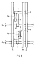
- the first inspection wiring 70 for right-side scan connecting wirings and the second inspection wiring 72 for right-side scan connecting wirings are adjacent to each other, and all of the right-side scan switching elements 69 1 to 69 7 are formed between the first inspection wiring 70 for right-side scan connecting wirings and the second inspection wiring 72 for right-side scan connecting wirings.
- the first inspection wiring 75 for left-side scan connecting wirings and the second inspection wiring 77 for left-side scan connecting wirings are adjacent to each other, and all of the left-side scan switching elements 74 1 to 74 6 are formed between the first inspection wiring 75 for left-side scan connecting wirings and the second inspection wiring 77 for left-side scan connecting wirings.
- the two base substrates are then adhered together after the sealant has been applied
- the two base substrates adhered together are then sectioned as mother substrates from which a prescribed number of liquid crystal panels 1 having an active matrix substrate 2 and an opposing substrate 3 are formed.
- Aliquid crystal material is injected into each of the liquid crystal panel 1 sectioned as mother substrates using a vacuum injection method, for example, through an inlet formed between the active matrix substrate 2 and the opposing substrate 3.
- the liquid crystal material may be injected using a drop injection method rather than a vacuum injection method. In this case, neither the inlet nor a process of sealing the inlet portion is required.
- the liquid crystal panel 1 shown in FIG. 1 is a single liquid crystal panel that has been sectioned as a mother substrate and injected with a liquid crystal material. Accordingly, although illustration thereof has been omitted, other liquid crystal panels exist above, below and to the left and right of the liquid crystal panel 1 shown in FIG. 1 .
- scan inspection signals are collectively input to the right-side scan connecting wirings 61 1 to 61 7 from the first inspection pad 64 for scan wirings. That is, the same scan inspection signal is input to each of the adjacent first right-side scan connecting wirings 61 1 , 61 3 , 61 5 and 61 7 formed on the first layer. In other words, the adjacent first right-side scan connecting wirings 61 1 , 61 3 , 61 5 and 61 7 have the same potential. Also, the same scan inspection signal is input to each of the adjacent second right-side scan connecting wirings 61 2 , 61 4 and 61 6 formed on the second layer.
- the present invention can, naturally, also be applied to an IPS (In-Plane Switching) mode liquid crystal panel in which common electrodes are formed on an active matrix substrate.
- IPS In-Plane Switching
- a transfer pad need not be formed on the active matrix substrate of an IPS mode liquid crystal paneL
- MVA Multi-Domain Vertical Aligned
- OCB Optically Compensated Bend
Claims (17)
- Aktivmatrixsubstrat (2), welches für eine Leitungsinspektion geeignet ist,
mit:einer Mehrzahl erster Leitungen (401 bis 407, 411 bis 416), die parallel zueinander in einem Anzeigebereich (4) ausgebildet sind,einer Mehrzahl zweiter Leitungen (421 bis 42i), die parallel zueinander und so ausgebildet sind, dass sie die Mehrzahl erster Leitungen (401 bis 407) im Anzeigebereich (4) überkreuzen,einer Mehrzahl erster Anschlüsse (51) und einer Mehrzahl zweiter Anschlüsse (52), die in einem Anschlussanordnungsbereich (5) angeordnet sind,einer Mehrzahl erster Verbindungsleitungen (611 bis 617, 651 bis 656), die außerhalb des Anzeigebereichs (4) angeordnet sind und die jeweils die Mehrzahl erster Leitungen (401 bis 407, 411 bis 416) und die Mehrzahl erster Anschlüsse (51) verbinden, undeiner Mehrzahl zweiter Verbindungsleitungen (811 bis 81i), die außerhalb des Anzeigebereichs (4) angeordnet sind und die jeweils die Mehrzahl zweiter Leitungen (421 bis 42i) und die Mehrzahl zweiter Anschlüsse (52) verbinden,wobei die Mehrzahl erster Verbindungsleitungen (611 bis 617, 651 bis 656) eine Mehrzahl dritter Verbindungsleitungen (611, 613, 615, 617, 651, 653, 655) und eine Mehrzahl vierter Verbindungsleitungen (612, 614, 616, 652, 654, 656) aufweisen,dadurch gekennzeichnet,
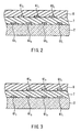
dass die dritten Verbindungsleitungen (611, 613, 615, 617, 651, 653, 655) auf einer selben Schicht ausgebildet sind, wie der Schicht, auf welcher die ersten Leitungen (401 bis 407, 411 bis 416) ausgebildet sind, und dass mindestens ein Teil der vierten Leitungen (612, 614, 616, 652, 654, 656) auf einer anderen Schicht als der Schicht ausgebildet sind, auf welcher die ersten Leitungen (401 bis 407, 411 bis 416) ausgebildet sind, mit einem isolierenden Material (7) dazwischen angeordnet, und
dass das Aktivmatrixsubstrat (2) aufweist:eine Mehrzahl erster Schaltelemente (691, 693, 695, 697, 741, 743, 745), die außerhalb des Anzeigebereichs (4) angeordnet sind und die jeweils mit der Mehrzahl dritter Verbindungsleitungen (611, 613, 615, 617, 651, 653, 655) verbunden sind,eine Mehrzahl zweiter Schaltelemente (692, 694, 696, 742, 744, 746), die außerhalb des Anzeigebereichs (4) angeordnet sind und die jeweils mit der Mehrzahl vierter Verbindungsleitungen (612, 614, 616, 652, 654, 656) verbunden sind,eine erste Prüfleitung (70, 75), die mit Ausgewählten (691, 695, 741, 745) unter der Mehrzahl erster Schaltelemente, die nicht zueinander benachbart sind, sowie mit zweiten Schaltelementen (694, 744) aus der Mehrzahl zweiter Schaltelemente verbunden sind, die nicht zueinander benachbart sind, undeine zweite Prüfleitung (72, 77), die mit Ausgewählten (693, 697, 743, 747) der ersten Schaltelemente unter der Mehrzahl erster Schaltelemente, die nicht zueinander benachbart sind und die nicht mit der ersten Prüfleitung (70, 75) sowie mit zweiten Schaltelemente (692, 696, 742, 746) unter der Mehrzahl zweiter Schaltelemente verbunden sind, die nicht zueinander benachbart sind und die nicht mit der ersten Prüfleitung (70, 75) verbunden sind. - Aktivmatrixsubstrat (2) nach Anspruch 1,
wobei die Mehrzahl erster Leitungen (401 bis 407, 411 bis 416) eine Mehrzahl dritter Leitungen (401 bis 407) aufweist, von denen jede ein Signaleingangsende (431 bis 437) an einem Ende aufweist, sowie eine Mehrzahl vierter Leitungen (411 bis 416), von denen jede ein Signaleingangsende (441 bis 446) an einem gegenüberliegenden Ende aufweist, wobei die dritten Leitungen (401 bis 407) und die vierten Leitungen (411 bis 416) alternierend im Anzeigebereich (4) ausgebildet sind,
wobei die Mehrzahl der dritten Verbindungsleitungen (611, 613, 615, 617, 651, 653, 655) eine Mehrzahl fünfter Verbindungsleitungen (611, 613, 615, 617) aufweist, welche jeweils die Mehrzahl erster Anschlüsse (51) und die Eingangsenden (431, 433, 435) der dritten Leitungen (401, 403, 405) unter der Mehrzahl dritter Leitungen verbinden, die nicht zueinander benachbart sind, sowie eine Mehrzahl sechster Verbindungsleitungen (651, 653, 655), die jeweils die Mehrzahl erster Anschlüsse (51) und die Eingangsenden (441, 443, 445) vierter Leitungen (411, 413, 415) unter der Mehrzahl vierter Leitungen verbinden, die nicht zueinander benachbart sind,
wobei die Mehrzahl vierter Verbindungsleitungen (612, 614, 616, 652, 654, 656) eine Mehrzahl siebter Verbindungsleitungen (612, 614, 616) aufweist, die jeweils die Mehrzahl erster Anschlüsse (51) und die Eingangsenden (43) dritter Leitungen unter der Mehrzahl dritter Leitungen verbinden, die nicht zueinander benachbart sind und die nicht mit den fünften Verbindungsleitungen verbunden sind, sowie eine Mehrzahl achter Verbindungsleitungen (652, 654, 656), die jeweils die Mehrzahl erster Anschlüsse (51) und die Eingangsenden (43) vierter Leitungen unter der Mehrzahl vierter Leitungen verbinden, die nicht zueinander benachbart sind und die nicht mit den sechsten Verbindungsleitungen verbunden sind,
wobei die ersten Schaltelemente (691, 693, 695, 697, 741, 743, 745) eine Mehrzahl dritter Schaltelemente (691, 693, 695, 697) aufweisen, die jeweils mit der Mehrzahl fünfter Verbindungsleitungen (611, 613, 615) verbunden sind, sowie eine Mehrzahl vierter Schaltelemente (741, 743, 745), die jeweils mit der Mehrzahl sechster Verbindungsleitungen (651, 653, 655) verbunden sind,
wobei die zweiten Schaltelemente (692, 694, 966, 742, 744, 746) eine Mehrzahl fünfter Schaltelemente (692, 694, 696) aufweist, die jeweils mit der Mehrzahl siebter Verbindungsleitungen (612, 614, 616) verbunden sind, sowie eine Mehrzahl sechster Schaltelemente (742, 744, 746), die jeweils mit der Mehrzahl achter Verbindungsleitungen (652, 654, 656) verbunden sind,
wobei die erste Prüfleitung (70, 75) aufweist:eine dritte Prüfleitung (70), die mit den dritten Schaltelementen (691, 695) unter der Mehrzahl dritter Schaltelemente verbunden ist, die nicht zueinander benachbart sind, sowie mit fünften Schaltelementen (694) unter der Mehrzahl fünfter Schaltelemente, die nicht zueinander benachbart sind, undeine vierte Prüfleitung (75), die mit vierten Schaltelementen (741, 745) unter der Mehrzahl vierter Schaltelemente verbunden ist, die nicht zueinander benachbart sind, sowie mit sechsten Schaltelementen (744) unter der Mehrzahl sechster Schaltelemente, die nicht zueinander benachbart sind, undwobei die zweite Prüfleitung (72) aufweist:eine fünfte Prüfleitung (72), die mit dritten Schaltelementen (692, 696) unter der Mehrzahl dritter Schaltelemente verbunden ist, die nicht benachbart zueinander sind und die nicht mit der dritten Prüfleitung verbunden sind, sowie mit fünften Schaltelementen (693, 697) unter der Mehrzahl fünfter Schaltelemente, die nicht zueinander benachbart sind und die nicht mit der dritten Prüfleitung verbunden sind, undeine sechste Prüfleitung (77), die mit vierten Schaltelementen (742, 746) unter der Mehrzahl vierter Schaltelemente verbunden ist, die nicht zueinander benachbart sind und die nicht mit der vierten Prüfleitung verbunden sind, sowie mit sechsten Schaltelementen (743) unter der Mehrzahl sechster Schaltelemente, die nicht zueinander benachbart sind und die nicht mit der vierten Prüfleitung verbunden sind. - Aktivmatrixsubstrat (2) nach Anspruch 2,
wobei die Mehrzahl dritter Schaltelemente (691, 693, 695, 697) und die Mehrzahl fünfter Schaltelemente (692, 694, 696) in einem peripheren Leitungsbereich (6) in Nachbarschaft zu den Eingangsenden (431 bis 437) der dritten Leitungen (401 bis 407) ausgebildet sind und
wobei die Mehrzahl vierter Schaltelemente (741, 743, 745) und die Mehrzahl sechster Schaltelemente (742, 744, 746) im peripheren Leitungsbereich (6) in Nachbarschaft zu den Eingangsenden der vierten Leitungen (441 bis 446) ausgebildet sind. - Aktivmatrixsubstrat (2) nach den Ansprüchen 2 oder 3,
wobei die dritte Prüfleitung (70) so im peripheren Leistungsbereich (6) ausgebildet ist, dass sie jede der Mehrzahl fünfter Verbindungsleitungen (611, 613, 615, 617) und jede der Mehrzahl siebter Verbindungsleitungen (612, 614, 616) überkreuzt,
wobei die fünfte Prüfleitung (72) so im peripheren Leitungsbereich (6) ausgebildet ist, dass sie jede der Mehrzahl fünfter Verbindungsleitungen 611, 613, 615, 617) und jede der Mehrzahl siebter Verbindungsleitungen (612, 614, 616) überkreuzt,
wobei die vierte Prüfleitung (75) so im peripheren Leitungsbereich (6) ausgebildet ist, dass sie jede der Mehrzahl sechster Verbindungsleitungen (651, 653, 655) und jede der Mehrzahl achter Verbindungsleitungen (652, 654, 656) überkreuzt, und
wobei die sechste Prüfung (77) im peripheren Leitungsbereich (6) so ausgebildet ist, dass sie jede der Mehrzahl sechster Verbindungsleitungen (651, 653, 655) und die jede der Mehrzahl achter Verbindungsleitungen (652, 654, 656) überkreuzt. - Aktivmatrixsubstrat (2) nach einem der Ansprüche 2 bis 4,
wobei die dritte Prüfleitung (70) und die fünfte Prüfleitung (72) zueinander benachbart ausgebildet sind,
wobei die vierte Prüfleitung (75) und die sechste Prüfleitung (77) zueinander benachbart ausgebildet sind,
wobei mindestens eines der Mehrzahl dritter Schaltelemente (691, 693, 695, 697) zwischen der dritten Prüfleitung (70) und der fünften Prüfleitung (72) ausgebildet ist,
wobei mindestens eines der Mehrzahl fünfter Schaltelemente (692, 694, 696) zwischen der dritten Prüfleitung (70) und der fünften Prüfleitung (72) ausgebildet ist,
wobei mindestens eines der Mehrzahl vierter Schaltelemente (741, 743, 745) zwischen der vierten Prüfleitung (75) und der sechsten Prüfleitung (77) ausgebildet ist, und
wobei mindestens eines der Mehrzahl sechster Schaltelemente (742, 744, 746) zwischen der vierten Prüfleitung (75) und der sechsten Prüfleitung (77) ausgebildet ist. - Aktivmatrixsubstrat (2) nach Anspruch 5,
wobei sämtliche der Mehrzahl dritter Schaltelemente (691, 693, 695, 697) zwischen der dritten Prüfleitung (70) und der fünften Prüfleitung (72) ausgebildet sind,
wobei sämtliche der Mehrzahl fünfter Schaltelemente (692, 694, 696) zwischen der dritten Prüfleitung (70) und der fünften Prüfleitung (72) ausgebildet sind,
wobei sämtliche der Mehrzahl vierter Schaltelemente (741, 743, 745) zwischen der vierten Prüfleitung (75) und der sechsten Prüfleitung (77) ausgebildet sind und
wobei sämtliche der Mehrzahl sechster Schaltelemente (742, 744, 746) zwischen der vierten Prüfleitung (75) und der sechsten Prüfleitung (77) ausgebildet sind. - Aktivmatrixsubstrat (2) nach einem der Ansprüche 2 bis 4,
wobei eine erste Steuerleitung (89) mit einer Gateelektrode jedes dritten Schaltelements (691, 693, 695, 697) und jedes fünften Schaltelements (692, 694, 696) verbunden zwischen der dritten Prüfleitung (70) und der fünften Prüfleitung (72) ausgebildet ist,
wobei die dritten Schaltelemente (691, 693, 695, 697) auf jeder Seite ausgebildet sind und die erste Steuerleitung (89) zwischen sich aufnehmen,
wobei die fünften Schaltelemente (692, 694, 696) auf jeder Seite ausgebildet sind und die erste Steuerleitung (89) zwischen sich aufnehmen,
wobei eine zweite Steuerleitung (89) mit einer Gateelektrode jedes vierten Schaltelements (741, 743, 745) und jedes sechsten Schaltelements (742, 744, 746) verbunden zwischen der vierten Prüfleitung (75) und der sechsten Prüfleitung (77) ausgebildet ist,
wobei die vierten Schaltelemente (741, 743, 745) auf jeder Seite ausgebildet sind und die zweite Steuerleitung (89) zwischen sich aufnehmen und
wobei die sechsten Schaltelemente (742, 744, 746) auf jeder Seite ausgebildet sind und die zweite Steuerleitung (89) zwischen sich aufnehmen. - Aktivmatrixsubstrat (2) nach einem der Ansprüche 2 bis 7,
welches des Weiteren aufweist:eine Mehrzahl erster Erweiterungsleitungen (53), die sich individuell von der Mehrzahl erster Anschlüsse (51), die jeweils verbunden sind mit der Mehrzahl fünfter Verbindungsleitungen (611, 613, 615, 617), und von der Mehrzahl erster Anschlüsse (51) erstrecken, die jeweils verbunden sind mit der Mehrzahl siebter Verbindungsleitungen (612, 614, 616),eine siebte Prüfleitung (63), die mit jeder der Mehrzahl erster Erweiterungsleitungen (53) verbunden ist,eine Mehrzahl zweiter Erweiterungsleitungen (54), die sich individuell von der Mehrzahl erster Anschlüsse (51), die jeweils mit der Mehrzahl sechster Verbindungsleitungen (651, 653, 655) verbunden sind, und von der Mehrzahl erster Anschlüsse (51) erstrecken, die jeweils mit der Mehrzahl von achten Verbindungsleitungen (652, 654, 656) verbunden sind undeine achte Prüfleitung (67), die mit jeder der Mehrzahl zweiter Erweiterungsleitungen (54) verbunden ist. - Aktivmatrixsubstrat (2) nach Anspruch 8,
wobei jede der Mehrzahl zweiter Leitungen (421 bis 42i) ein Signaleingangsende (451 bis 45i) an einem Ende aufweist und
wobei das Aktivmatrixsubstrat (2) des Weiteren aufweist:eine Mehrzahl siebter Schaltelemente (821 bis 82i), die an einem gegenüberliegende Enden der zweiten Leitungen (421 bis 42i) verbunden sind,eine neunte Prüfleitung (83), die mit siebten Schaltelementen (821 bis 82i) unter der Mehrzahl siebter Schaltelemente (821 bis 82i) verbunden sind, die nicht benachbart zueinander sind, undeine zehnte Prüfleitung (85), die mit siebten Schaltelementen (821 bis 82i) unter der Mehrzahl siebter Schaltelemente (821 bis 82i) verbunden ist, die nicht zueinander benachbart sind und die nicht mit der neunten Prüfleitung (83) verbunden sind. - Aktivmatrixsubstrat (2) nach Anspruch 1,
wobei die Mehrzahl erster Leitungen (401 bis 407, 411 bis 416) eine erste Gruppe erster Leitungen (401 bis 407), die benachbart zueinander sind und die jeweils an einem Ende ein Signaleingangsende (431 bis 437) aufweisen, sowie eine zweite Gruppe erster Leitungen (411 bis 416) aufweist, die benachbart zueinander sind und die jeweils ein Signaleingangsende (441 bis 446) an einem gegenüberliegenden Ende aufweisen, und
wobei die Mehrzahl erster Verbindungsleitungen (611 bis 617, 651 bis 656) jeweils die Mehrzahl erster Anschlüsse (51) und die Eingangsenden (431 bis 437) der ersten Gruppe erster Leitungen (401 bis 407) verbinden und jeweils die Mehrzahl erster Anschlüsse (51) und die Eingangsenden der zweiten Gruppe erster Leitungen (401 bis 407) verbinden. - Aktivmatrixsubstrat (2) nach einem der Ansprüche 1 bis 10,
wobei die ersten Leitungen (401 bis 407, 411 bis 416) Abtastleitungen sind und
wobei die zweiten Leitungen (421 bis 42i) Datenleitungen sind. - Anzeigeeinrichtung (1),
mit einem Aktivmatrixsubstrat (2) nach einem der Ansprüche 1 bis 11. - Anzeigeeinrichtung (1) nach Anspruch 12,
wobei wie Anzeigeeinrichtung (1) eine Flüssigkristallanzeigeeinrichtung ist. - Verfahren zum Prüfen eines Aktivmatrixsubstrats (2) nach Anspruch 1 oder einer Anzeigeeinrichtung (1) mit einem Aktivmatrixsubstrat (2) nach Anspruch 1,
mit den Schritten:Prüfen der dritten Verbindungsleitungen (611, 613, 615, 617, 651, 653, 655) durch Eingeben gegenseitig unabhängiger Prüfsignale in die erste Prüfleitung (70, 75) und die zweite Prüfleitung (72, 77), während die ersten Schaltelemente (693, 697, 743, 747) in einem EIN-Zustand gehalten werden, undPrüfen der vierten Verbindungsleitungen (612, 614, 616, 652, 654, 656) durch Eingeben gegenseitig unabhängiger Prüfsignale in die erste Prüfleitung (70, 75) und die zweite Prüfleitung (72, 77), während die zweiten Schaltelemente (692, 694, 696, 742, 744, 746) in einem EIN-Zustand gehalten werden. - Verfahren zum Prüfen eines Aktivmatrixsubstrats (2) nach einem der Ansprüche 2 bis 7 oder einer Anzeigeeinrichtung (1) mit dem Aktivmatrixsubstrat (2) nach einem der Ansprüche 2 bis 7,
mit den Schritten:Prüfen der fünften Verbindungsleitungen (611, 613, 615, 617) durch Eingeben gegenseitig unabhängiger Prüfsignale in die dritte Prüfleitung (70) und die fünfte Prüfleitung (72), während die dritten Schaltelemente (691, 693, 695, 697) in einem EIN-Zustand gehalten werden,Prüfen der siebten Verbindungsleitungen (612, 614, 616) durch Eingeben gegenseitig unabhängiger Prüfsignale in die dritte Prüfleitung (70) und die fünfte Prüfleitung (72), während die fünften Schaltelemente (692, 694, 696) in einem EIN-Zustand gehalten werden,Prüfen der sechsten Verbindungsleitungen (651, 653, 655) durch Eingeben gegenseitig unabhängiger Prüfsignale in die vierte Prüfleitung (75) und die sechste Prüfleitung (77), während die vierten Schaltelemente (741, 743, 745) in einem EIN-Zustand gehalten werden, undPrüfen der achten Verbindungsleitungen durch Eingeben gegenseitig unabhängiger Prüfsignale in die vierte Prüfleitung (75) und die sechste Prüfleitung (77), während die sechsten Schaltelemente (743) in einem EIN-Zustand gehalten werden. - Verfahren zum Prüfen eines Aktivmatrixsubstrats (2) nach Anspruch 8 oder einer Anzeigeeinrichtung (1) mit dem Aktivmatrixsubstrat (2) nach Anspruch 8,
mit den Schritten:Prüfen der dritten Leitungen (401 bis 407) durch Eingaben eines Prüfsignals von der siebten Prüfleitung;Prüfen der vierten Leitungen (411 bis 416) durch Eingaben eines Prüfsignals von der achten Prüfleitung;Abtrennen der Mehrzahl erster Erweiterungsleitungen (53) und der Mehrzahl zweiter Erweiterungsleitungen (54);Prüfen der fünften Verbindungsleitungen (611, 613, 615, 617) durch Eingeben gegenseitig unabhängiger Prüfsignale in die dritte Prüfleitung (70) und die fünfte Prüfleitung (72), während die dritten Schaltelemente (691, 693, 695, 697) in einem EIN-Zustand gehalten werden,Prüfen der siebten Verbindungsleitungen (612, 614, 616) durch Eingeben gegenseitig unabhängiger Prüfsignale in die dritte Prüfleitung (70) und die fünfte Prüfleitung (72), während die fünften Schaltelemente (692, 694, 696) in einem EIN-Zustand gehalten werden,Prüfen der sechsten Verbindungsleitungen (651, 653, 655) durch Eingeben gegenseitig unabhängiger Prüfsignale in die vierte Prüfleitung (75) und die sechste Prüfleitung (77), während die vierten Schaltelemente (741, 743, 745) in einem EIN-Zustand gehalten werden, undPrüfen der achten Verbindungsleitungen durch Eingeben gegenseitig unabhängiger Prüfsignale in die vierte Prüfleitung (75) und die sechste Prüfleitung (77), während die sechsten Schaltelemente (743) in einem EIN-Zustand gehalten werden. - Verfahren zum Prüfen eines Aktivmatrixsubstrats (2) nach Anspruch 9 oder einer Anzeigeeinrichtung (1) mit dem Aktivmatrixsubstrat (2) nach Anspruch 9,
mit den Schritten:Prüfen der dritten Leitungen (401 bis 407) durch Eingaben eines Prüfsignals von der siebten Prüfleitung;Prüfen der vierten Leitungen (411 bis 416) durch Eingaben eines Prüfsignals von der achten Prüfleitung;Prüfen der zweiten Leitungen (421 bis 42i) durch Eingeben gegenseitig unabhängiger Prüfsignale in die neunte Prüfleitung (83) und die zehnte Prüfleitung (85), während die siebten Schaltelemente in einem EIN-Zustand gehalten werden,Abtrennen der Mehrzahl erster Erweiterungsleitungen und der Mehrzahl zweiter Erweiterungsleitungen;Prüfen der fünften Verbindungsleitungen (611, 613, 615, 617) durch Eingeben gegenseitig unabhängiger Prüfsignale in die dritte Prüfleitung (70) und die fünfte Prüfleitung (72), während die dritten Schaltelemente (691, 693, 695, 697) in einem EIN-Zustand gehalten werden,Prüfen der siebten Verbindungsleitungen (612, 614, 616) durch Eingeben gegenseitig unabhängiger Prüfsignale in die dritte Prüfleitung (70) und die fünfte Prüfleitung (72), während die fünften Schaltelemente (692, 694, 696) in einem EIN-Zustand gehalten werden,Prüfen der sechsten Verbindungsleitungen (651, 653, 655) durch Eingeben gegenseitig unabhängiger Prüfsignale in die vierte Prüfleitung (75) und die sechste Prüfleitung (77), während die vierten Schaltelemente (741, 743, 745) in einem EIN-Zustand gehalten werden, undPrüfen der achten Verbindungsleitungen durch Eingeben gegenseitig unabhängiger Prüfsignale in die vierte Prüfleitung (75) und die sechste Prüfleitung (77), während die sechsten Schaltelemente (743) in einem EIN-Zustand gehalten werden.
Applications Claiming Priority (2)
| Application Number | Priority Date | Filing Date | Title |
|---|---|---|---|
| JP2008129866 | 2008-05-16 | ||
| PCT/JP2009/058317 WO2009139290A1 (ja) | 2008-05-16 | 2009-04-28 | アクティブマトリクス基板、表示装置、アクティブマトリクス基板の検査方法、および表示装置の検査方法 |
Publications (3)
| Publication Number | Publication Date |
|---|---|
| EP2275861A1 EP2275861A1 (de) | 2011-01-19 |
| EP2275861A4 EP2275861A4 (de) | 2011-08-24 |
| EP2275861B1 true EP2275861B1 (de) | 2013-10-02 |
Family
ID=41318661
Family Applications (1)
| Application Number | Title | Priority Date | Filing Date |
|---|---|---|---|
| EP09746497.8A Not-in-force EP2275861B1 (de) | 2008-05-16 | 2009-04-28 | Aktivmatrixsubstrat, anzeigevorrichtung, verfahren zur prüfung eines aktivmatrixsubstrats und verfahren zur prüfung einer anzeigevorrichtung |
Country Status (7)
| Country | Link |
|---|---|
| US (1) | US8582068B2 (de) |
| EP (1) | EP2275861B1 (de) |
| JP (2) | JP5036865B2 (de) |
| CN (1) | CN101999095B (de) |
| BR (1) | BRPI0912347A2 (de) |
| RU (1) | RU2453881C1 (de) |
| WO (1) | WO2009139290A1 (de) |
Families Citing this family (25)
| Publication number | Priority date | Publication date | Assignee | Title |
|---|---|---|---|---|
| RU2475866C2 (ru) | 2008-07-23 | 2013-02-20 | Шарп Кабусики Кайся | Подложка активной матрицы, дисплейное устройство, способ проверки подложки активной матрицы и способ проверки дисплейного устройства |
| JP2011186216A (ja) * | 2010-03-09 | 2011-09-22 | Hitachi Displays Ltd | 液晶表示装置及びその製造方法 |
| US9614001B2 (en) | 2010-06-28 | 2017-04-04 | Sharp Kabushiki Kaisha | Active matrix substrate including signal terminals additional signal terminals and switching elements for testing the active matrix substrate |
| WO2012147962A1 (ja) * | 2011-04-28 | 2012-11-01 | シャープ株式会社 | 液晶表示装置 |
| KR101947163B1 (ko) * | 2012-02-10 | 2019-02-13 | 삼성디스플레이 주식회사 | 유기 발광 표시 장치 |
| CN104246860B (zh) * | 2012-04-25 | 2016-08-17 | 夏普株式会社 | 矩阵基板和显示装置 |
| KR101981531B1 (ko) | 2012-10-19 | 2019-05-23 | 엘지디스플레이 주식회사 | 터치 스크린 패널 |
| JP6051011B2 (ja) * | 2012-10-22 | 2016-12-21 | 株式会社ジャパンディスプレイ | 液晶表示装置およびその製造方法 |
| KR101992273B1 (ko) * | 2012-10-22 | 2019-10-01 | 삼성디스플레이 주식회사 | 유기전계발광 표시장치 및 그 검사방법 |
| KR102043624B1 (ko) * | 2012-12-17 | 2019-11-12 | 엘지디스플레이 주식회사 | 액정표시장치 및 그 구동방법 |
| CN103713410A (zh) | 2013-12-31 | 2014-04-09 | 京东方科技集团股份有限公司 | 阵列基板及显示装置 |
| TWI571989B (zh) * | 2014-01-28 | 2017-02-21 | 友達光電股份有限公司 | 顯示基板結構 |
| WO2016080291A1 (ja) * | 2014-11-21 | 2016-05-26 | シャープ株式会社 | 表示装置 |
| US10228595B2 (en) * | 2014-11-21 | 2019-03-12 | Sharp Kabushiki Kaisha | Display device with layered wiring structure for external connection |
| KR102349282B1 (ko) * | 2015-03-27 | 2022-01-11 | 삼성디스플레이 주식회사 | 표시 장치 및 이의 제조 방법 |
| KR102387786B1 (ko) * | 2015-07-28 | 2022-04-15 | 엘지디스플레이 주식회사 | 백플레인 기판 및 이를 이용한 플렉서블 디스플레이 |
| KR20170028464A (ko) * | 2015-09-03 | 2017-03-14 | 삼성디스플레이 주식회사 | 표시 장치 |
| KR102403234B1 (ko) | 2016-06-20 | 2022-05-27 | 삼성디스플레이 주식회사 | 표시 장치 |
| JP6152464B1 (ja) | 2016-11-05 | 2017-06-21 | 株式会社セレブレクス | 狭額縁ディスプレイモジュール及びデータ出力装置 |
| JP2018128487A (ja) * | 2017-02-06 | 2018-08-16 | セイコーエプソン株式会社 | 電気光学パネル、電気光学装置および電子機器 |
| WO2019031395A1 (ja) * | 2017-08-10 | 2019-02-14 | シャープ株式会社 | Tftモジュール、tftモジュールを備えた走査アンテナ、tftモジュールを備えた装置の駆動方法、およびtftモジュールを備えた装置の製造方法 |
| US10852591B2 (en) * | 2018-06-29 | 2020-12-01 | Sharp Kabushiki Kaisha | Image display device |
| WO2020039554A1 (ja) * | 2018-08-23 | 2020-02-27 | シャープ株式会社 | アクティブマトリクス基板、表示装置及び母基板 |
| KR20200053720A (ko) * | 2018-11-08 | 2020-05-19 | 삼성디스플레이 주식회사 | 표시장치 |
| CN110649045B (zh) * | 2019-10-31 | 2022-08-26 | 京东方科技集团股份有限公司 | 有机发光显示面板及显示装置 |
Family Cites Families (23)
| Publication number | Priority date | Publication date | Assignee | Title |
|---|---|---|---|---|
| JP3247799B2 (ja) * | 1994-06-09 | 2002-01-21 | シャープ株式会社 | 液晶表示パネルおよびその検査方法 |
| JP3276557B2 (ja) | 1996-05-23 | 2002-04-22 | 三菱電機株式会社 | 液晶表示装置 |
| JPH11119683A (ja) * | 1997-10-13 | 1999-04-30 | Fujitsu Ltd | 液晶表示パネルの検査方法 |
| KR100276442B1 (ko) * | 1998-02-20 | 2000-12-15 | 구본준 | 액정표시장치 제조방법 및 그 제조방법에 의한 액정표시장치 |
| JP3634138B2 (ja) * | 1998-02-23 | 2005-03-30 | 株式会社 日立ディスプレイズ | 液晶表示装置 |
| GB2342213B (en) * | 1998-09-30 | 2003-01-22 | Lg Philips Lcd Co Ltd | Thin film transistor substrate with testing circuit |
| RU2173909C1 (ru) | 2000-06-15 | 2001-09-20 | Научно-исследовательский институт "Волга" | Катодолюминесцентный матричный экран |
| JP2002098992A (ja) * | 2000-09-22 | 2002-04-05 | Toshiba Corp | 液晶表示装置 |
| JP3909572B2 (ja) | 2001-09-28 | 2007-04-25 | 株式会社日立製作所 | 表示装置 |
| JP4006012B2 (ja) | 2001-09-28 | 2007-11-14 | 株式会社日立製作所 | 表示装置および液晶表示装置 |
| JP2003241217A (ja) | 2002-02-15 | 2003-08-27 | Matsushita Electric Ind Co Ltd | 液晶表示パネル及びそれを用いた液晶表示装置 |
| JP4006284B2 (ja) | 2002-07-17 | 2007-11-14 | 株式会社 日立ディスプレイズ | 液晶表示装置 |
| KR100923056B1 (ko) * | 2002-09-16 | 2009-10-22 | 삼성전자주식회사 | 표시 장치 및 이의 제조방법 |
| JP2004226931A (ja) | 2003-01-27 | 2004-08-12 | Kyocera Corp | 液晶表示装置 |
| JP2004325956A (ja) | 2003-04-25 | 2004-11-18 | Sharp Corp | 表示装置及びその製造方法 |
| JP4178090B2 (ja) | 2003-09-19 | 2008-11-12 | シャープ株式会社 | 電極配線基板および表示装置 |
| JP2005241988A (ja) | 2004-02-26 | 2005-09-08 | Alps Electric Co Ltd | 表示装置 |
| JP2005266529A (ja) * | 2004-03-19 | 2005-09-29 | Sharp Corp | 表示装置の製造方法及び表示装置 |
| JP2006317763A (ja) * | 2005-05-13 | 2006-11-24 | Toshiba Matsushita Display Technology Co Ltd | 液晶表示装置 |
| KR101129618B1 (ko) * | 2005-07-19 | 2012-03-27 | 삼성전자주식회사 | 액정 표시 패널 및 이의 검사 방법과 이의 제조방법 |
| US7847577B2 (en) | 2006-07-31 | 2010-12-07 | Sharp Kabushiki Kaisha | Active matrix substrate, display device, and active matrix substrate inspecting method |
| JP2008064961A (ja) * | 2006-09-06 | 2008-03-21 | Mitsubishi Electric Corp | 配線構造、及び表示装置 |
| JP4813621B2 (ja) * | 2008-03-14 | 2011-11-09 | シャープ株式会社 | アクティブマトリクス基板、表示装置、アクティブマトリクス基板の検査方法、および表示装置の検査方法 |
-
2009
- 2009-04-28 EP EP09746497.8A patent/EP2275861B1/de not_active Not-in-force
- 2009-04-28 US US12/934,896 patent/US8582068B2/en active Active
- 2009-04-28 BR BRPI0912347A patent/BRPI0912347A2/pt not_active IP Right Cessation
- 2009-04-28 CN CN2009801129252A patent/CN101999095B/zh not_active Expired - Fee Related
- 2009-04-28 JP JP2010511945A patent/JP5036865B2/ja not_active Expired - Fee Related
- 2009-04-28 RU RU2010146451/28A patent/RU2453881C1/ru not_active IP Right Cessation
- 2009-04-28 WO PCT/JP2009/058317 patent/WO2009139290A1/ja active Application Filing
-
2012
- 2012-07-03 JP JP2012149592A patent/JP5379271B2/ja not_active Expired - Fee Related
Also Published As
| Publication number | Publication date |
|---|---|
| EP2275861A4 (de) | 2011-08-24 |
| CN101999095A (zh) | 2011-03-30 |
| CN101999095B (zh) | 2012-05-09 |
| US8582068B2 (en) | 2013-11-12 |
| JP5036865B2 (ja) | 2012-09-26 |
| BRPI0912347A2 (pt) | 2015-10-13 |
| EP2275861A1 (de) | 2011-01-19 |
| JP2012212168A (ja) | 2012-11-01 |
| RU2453881C1 (ru) | 2012-06-20 |
| JPWO2009139290A1 (ja) | 2011-09-15 |
| US20110018142A1 (en) | 2011-01-27 |
| WO2009139290A1 (ja) | 2009-11-19 |
| JP5379271B2 (ja) | 2013-12-25 |
Similar Documents
| Publication | Publication Date | Title |
|---|---|---|
| EP2275861B1 (de) | Aktivmatrixsubstrat, anzeigevorrichtung, verfahren zur prüfung eines aktivmatrixsubstrats und verfahren zur prüfung einer anzeigevorrichtung | |
| EP2317492B1 (de) | Aktivmatrixsubstrat, anzeigeanordnung, verfahren zum untersuchen des aktivmatrixsubstrats und verfahren zum untersuchen der anzeigeanordnung | |
| US10802358B2 (en) | Display device with signal lines routed to decrease size of non-display area | |
| JP5285119B2 (ja) | アクティブマトリクス基板、表示装置、アクティブマトリクス基板の検査方法、および表示装置の検査方法 | |
| US7847577B2 (en) | Active matrix substrate, display device, and active matrix substrate inspecting method | |
| US9405162B2 (en) | Active matrix display device with auxiliary repair line | |
| US20130016077A1 (en) | System for display images and fabrication method thereof | |
| US20240087492A1 (en) | Display substrate, test method for the same and display device | |
| JP2007183446A (ja) | 電気光学装置、電気光学装置用基板、電気光学装置の製造方法、電気光学装置用基板の製造方法 |
Legal Events
| Date | Code | Title | Description |
|---|---|---|---|
| PUAI | Public reference made under article 153(3) epc to a published international application that has entered the european phase |
Free format text: ORIGINAL CODE: 0009012 |
|
| 17P | Request for examination filed |
Effective date: 20101109 |
|
| AK | Designated contracting states |
Kind code of ref document: A1 Designated state(s): AT BE BG CH CY CZ DE DK EE ES FI FR GB GR HR HU IE IS IT LI LT LU LV MC MK MT NL NO PL PT RO SE SI SK TR |
|
| AX | Request for extension of the european patent |
Extension state: AL BA RS |
|
| A4 | Supplementary search report drawn up and despatched |
Effective date: 20110725 |
|
| DAX | Request for extension of the european patent (deleted) | ||
| RIC1 | Information provided on ipc code assigned before grant |
Ipc: G09F 9/00 20060101ALI20110719BHEP Ipc: G02F 1/1345 20060101ALI20110719BHEP Ipc: G09F 9/30 20060101ALI20110719BHEP Ipc: G02F 1/1368 20060101AFI20110719BHEP |
|
| REG | Reference to a national code |
Ref country code: DE Ref legal event code: R079 Ref document number: 602009019191 Country of ref document: DE Free format text: PREVIOUS MAIN CLASS: G02F0001136800 Ipc: G02F0001136200 |
|
| GRAP | Despatch of communication of intention to grant a patent |
Free format text: ORIGINAL CODE: EPIDOSNIGR1 |
|
| RIC1 | Information provided on ipc code assigned before grant |
Ipc: G02F 1/1345 20060101ALI20130308BHEP Ipc: G02F 1/1362 20060101AFI20130308BHEP |
|
| INTG | Intention to grant announced |
Effective date: 20130417 |
|
| GRAS | Grant fee paid |
Free format text: ORIGINAL CODE: EPIDOSNIGR3 |
|
| GRAA | (expected) grant |
Free format text: ORIGINAL CODE: 0009210 |
|
| AK | Designated contracting states |
Kind code of ref document: B1 Designated state(s): AT BE BG CH CY CZ DE DK EE ES FI FR GB GR HR HU IE IS IT LI LT LU LV MC MK MT NL NO PL PT RO SE SI SK TR |
|
| REG | Reference to a national code |
Ref country code: GB Ref legal event code: FG4D |
|
| REG | Reference to a national code |
Ref country code: AT Ref legal event code: REF Ref document number: 634888 Country of ref document: AT Kind code of ref document: T Effective date: 20131015 Ref country code: CH Ref legal event code: EP |
|
| REG | Reference to a national code |
Ref country code: IE Ref legal event code: FG4D |
|
| REG | Reference to a national code |
Ref country code: DE Ref legal event code: R096 Ref document number: 602009019191 Country of ref document: DE Effective date: 20131128 |
|
| REG | Reference to a national code |
Ref country code: NL Ref legal event code: T3 |
|
| REG | Reference to a national code |
Ref country code: AT Ref legal event code: MK05 Ref document number: 634888 Country of ref document: AT Kind code of ref document: T Effective date: 20131002 |
|
| PG25 | Lapsed in a contracting state [announced via postgrant information from national office to epo] |
Ref country code: SI Free format text: LAPSE BECAUSE OF FAILURE TO SUBMIT A TRANSLATION OF THE DESCRIPTION OR TO PAY THE FEE WITHIN THE PRESCRIBED TIME-LIMIT Effective date: 20131002 |
|
| REG | Reference to a national code |
Ref country code: LT Ref legal event code: MG4D |
|
| PG25 | Lapsed in a contracting state [announced via postgrant information from national office to epo] |
Ref country code: LT Free format text: LAPSE BECAUSE OF FAILURE TO SUBMIT A TRANSLATION OF THE DESCRIPTION OR TO PAY THE FEE WITHIN THE PRESCRIBED TIME-LIMIT Effective date: 20131002 Ref country code: NO Free format text: LAPSE BECAUSE OF FAILURE TO SUBMIT A TRANSLATION OF THE DESCRIPTION OR TO PAY THE FEE WITHIN THE PRESCRIBED TIME-LIMIT Effective date: 20140102 Ref country code: CZ Free format text: LAPSE BECAUSE OF FAILURE TO SUBMIT A TRANSLATION OF THE DESCRIPTION OR TO PAY THE FEE WITHIN THE PRESCRIBED TIME-LIMIT Effective date: 20131002 Ref country code: SE Free format text: LAPSE BECAUSE OF FAILURE TO SUBMIT A TRANSLATION OF THE DESCRIPTION OR TO PAY THE FEE WITHIN THE PRESCRIBED TIME-LIMIT Effective date: 20131002 Ref country code: BE Free format text: LAPSE BECAUSE OF FAILURE TO SUBMIT A TRANSLATION OF THE DESCRIPTION OR TO PAY THE FEE WITHIN THE PRESCRIBED TIME-LIMIT Effective date: 20131002 Ref country code: IS Free format text: LAPSE BECAUSE OF FAILURE TO SUBMIT A TRANSLATION OF THE DESCRIPTION OR TO PAY THE FEE WITHIN THE PRESCRIBED TIME-LIMIT Effective date: 20140202 Ref country code: FI Free format text: LAPSE BECAUSE OF FAILURE TO SUBMIT A TRANSLATION OF THE DESCRIPTION OR TO PAY THE FEE WITHIN THE PRESCRIBED TIME-LIMIT Effective date: 20131002 Ref country code: HR Free format text: LAPSE BECAUSE OF FAILURE TO SUBMIT A TRANSLATION OF THE DESCRIPTION OR TO PAY THE FEE WITHIN THE PRESCRIBED TIME-LIMIT Effective date: 20131002 |
|
| PG25 | Lapsed in a contracting state [announced via postgrant information from national office to epo] |
Ref country code: PL Free format text: LAPSE BECAUSE OF FAILURE TO SUBMIT A TRANSLATION OF THE DESCRIPTION OR TO PAY THE FEE WITHIN THE PRESCRIBED TIME-LIMIT Effective date: 20131002 Ref country code: AT Free format text: LAPSE BECAUSE OF FAILURE TO SUBMIT A TRANSLATION OF THE DESCRIPTION OR TO PAY THE FEE WITHIN THE PRESCRIBED TIME-LIMIT Effective date: 20131002 Ref country code: CY Free format text: LAPSE BECAUSE OF FAILURE TO SUBMIT A TRANSLATION OF THE DESCRIPTION OR TO PAY THE FEE WITHIN THE PRESCRIBED TIME-LIMIT Effective date: 20131002 Ref country code: ES Free format text: LAPSE BECAUSE OF FAILURE TO SUBMIT A TRANSLATION OF THE DESCRIPTION OR TO PAY THE FEE WITHIN THE PRESCRIBED TIME-LIMIT Effective date: 20131002 Ref country code: LV Free format text: LAPSE BECAUSE OF FAILURE TO SUBMIT A TRANSLATION OF THE DESCRIPTION OR TO PAY THE FEE WITHIN THE PRESCRIBED TIME-LIMIT Effective date: 20131002 |
|
| PG25 | Lapsed in a contracting state [announced via postgrant information from national office to epo] |
Ref country code: PT Free format text: LAPSE BECAUSE OF FAILURE TO SUBMIT A TRANSLATION OF THE DESCRIPTION OR TO PAY THE FEE WITHIN THE PRESCRIBED TIME-LIMIT Effective date: 20140203 |
|
| REG | Reference to a national code |
Ref country code: DE Ref legal event code: R097 Ref document number: 602009019191 Country of ref document: DE |
|
| PG25 | Lapsed in a contracting state [announced via postgrant information from national office to epo] |
Ref country code: EE Free format text: LAPSE BECAUSE OF FAILURE TO SUBMIT A TRANSLATION OF THE DESCRIPTION OR TO PAY THE FEE WITHIN THE PRESCRIBED TIME-LIMIT Effective date: 20131002 |
|
| PLBE | No opposition filed within time limit |
Free format text: ORIGINAL CODE: 0009261 |
|
| STAA | Information on the status of an ep patent application or granted ep patent |
Free format text: STATUS: NO OPPOSITION FILED WITHIN TIME LIMIT |
|
| PG25 | Lapsed in a contracting state [announced via postgrant information from national office to epo] |
Ref country code: IT Free format text: LAPSE BECAUSE OF FAILURE TO SUBMIT A TRANSLATION OF THE DESCRIPTION OR TO PAY THE FEE WITHIN THE PRESCRIBED TIME-LIMIT Effective date: 20131002 Ref country code: RO Free format text: LAPSE BECAUSE OF FAILURE TO SUBMIT A TRANSLATION OF THE DESCRIPTION OR TO PAY THE FEE WITHIN THE PRESCRIBED TIME-LIMIT Effective date: 20131002 Ref country code: SK Free format text: LAPSE BECAUSE OF FAILURE TO SUBMIT A TRANSLATION OF THE DESCRIPTION OR TO PAY THE FEE WITHIN THE PRESCRIBED TIME-LIMIT Effective date: 20131002 |
|
| PGFP | Annual fee paid to national office [announced via postgrant information from national office to epo] |
Ref country code: DE Payment date: 20140430 Year of fee payment: 6 Ref country code: NL Payment date: 20140308 Year of fee payment: 6 |
|
| 26N | No opposition filed |
Effective date: 20140703 |
|
| PG25 | Lapsed in a contracting state [announced via postgrant information from national office to epo] |
Ref country code: DK Free format text: LAPSE BECAUSE OF FAILURE TO SUBMIT A TRANSLATION OF THE DESCRIPTION OR TO PAY THE FEE WITHIN THE PRESCRIBED TIME-LIMIT Effective date: 20131002 |
|
| REG | Reference to a national code |
Ref country code: DE Ref legal event code: R097 Ref document number: 602009019191 Country of ref document: DE Effective date: 20140703 |
|
| PG25 | Lapsed in a contracting state [announced via postgrant information from national office to epo] |
Ref country code: MC Free format text: LAPSE BECAUSE OF FAILURE TO SUBMIT A TRANSLATION OF THE DESCRIPTION OR TO PAY THE FEE WITHIN THE PRESCRIBED TIME-LIMIT Effective date: 20131002 Ref country code: LU Free format text: LAPSE BECAUSE OF FAILURE TO SUBMIT A TRANSLATION OF THE DESCRIPTION OR TO PAY THE FEE WITHIN THE PRESCRIBED TIME-LIMIT Effective date: 20140428 |
|
| REG | Reference to a national code |
Ref country code: CH Ref legal event code: PL |
|
| GBPC | Gb: european patent ceased through non-payment of renewal fee |
Effective date: 20140428 |
|
| REG | Reference to a national code |
Ref country code: FR Ref legal event code: ST Effective date: 20141231 |
|
| REG | Reference to a national code |
Ref country code: IE Ref legal event code: MM4A |
|
| PG25 | Lapsed in a contracting state [announced via postgrant information from national office to epo] |
Ref country code: CH Free format text: LAPSE BECAUSE OF NON-PAYMENT OF DUE FEES Effective date: 20140430 Ref country code: GB Free format text: LAPSE BECAUSE OF NON-PAYMENT OF DUE FEES Effective date: 20140428 Ref country code: LI Free format text: LAPSE BECAUSE OF NON-PAYMENT OF DUE FEES Effective date: 20140430 |
|
| PG25 | Lapsed in a contracting state [announced via postgrant information from national office to epo] |
Ref country code: FR Free format text: LAPSE BECAUSE OF NON-PAYMENT OF DUE FEES Effective date: 20140430 |
|
| PG25 | Lapsed in a contracting state [announced via postgrant information from national office to epo] |
Ref country code: IE Free format text: LAPSE BECAUSE OF NON-PAYMENT OF DUE FEES Effective date: 20140428 |
|
| REG | Reference to a national code |
Ref country code: DE Ref legal event code: R119 Ref document number: 602009019191 Country of ref document: DE |
|
| REG | Reference to a national code |
Ref country code: NL Ref legal event code: MM Effective date: 20150501 |
|
| PG25 | Lapsed in a contracting state [announced via postgrant information from national office to epo] |
Ref country code: DE Free format text: LAPSE BECAUSE OF NON-PAYMENT OF DUE FEES Effective date: 20151103 |
|
| PG25 | Lapsed in a contracting state [announced via postgrant information from national office to epo] |
Ref country code: MT Free format text: LAPSE BECAUSE OF FAILURE TO SUBMIT A TRANSLATION OF THE DESCRIPTION OR TO PAY THE FEE WITHIN THE PRESCRIBED TIME-LIMIT Effective date: 20131002 Ref country code: NL Free format text: LAPSE BECAUSE OF NON-PAYMENT OF DUE FEES Effective date: 20150501 |
|
| PG25 | Lapsed in a contracting state [announced via postgrant information from national office to epo] |
Ref country code: NO Free format text: LAPSE BECAUSE OF FAILURE TO SUBMIT A TRANSLATION OF THE DESCRIPTION OR TO PAY THE FEE WITHIN THE PRESCRIBED TIME-LIMIT Effective date: 20140101 |
|
| PG25 | Lapsed in a contracting state [announced via postgrant information from national office to epo] |
Ref country code: GR Free format text: LAPSE BECAUSE OF FAILURE TO SUBMIT A TRANSLATION OF THE DESCRIPTION OR TO PAY THE FEE WITHIN THE PRESCRIBED TIME-LIMIT Effective date: 20140103 Ref country code: BG Free format text: LAPSE BECAUSE OF FAILURE TO SUBMIT A TRANSLATION OF THE DESCRIPTION OR TO PAY THE FEE WITHIN THE PRESCRIBED TIME-LIMIT Effective date: 20131002 |
|
| PG25 | Lapsed in a contracting state [announced via postgrant information from national office to epo] |
Ref country code: HU Free format text: LAPSE BECAUSE OF FAILURE TO SUBMIT A TRANSLATION OF THE DESCRIPTION OR TO PAY THE FEE WITHIN THE PRESCRIBED TIME-LIMIT; INVALID AB INITIO Effective date: 20090428 Ref country code: TR Free format text: LAPSE BECAUSE OF FAILURE TO SUBMIT A TRANSLATION OF THE DESCRIPTION OR TO PAY THE FEE WITHIN THE PRESCRIBED TIME-LIMIT Effective date: 20131002 |
|
| PG25 | Lapsed in a contracting state [announced via postgrant information from national office to epo] |
Ref country code: MK Free format text: LAPSE BECAUSE OF FAILURE TO SUBMIT A TRANSLATION OF THE DESCRIPTION OR TO PAY THE FEE WITHIN THE PRESCRIBED TIME-LIMIT Effective date: 20131002 |