EP2255255B1 - Befestigungselement, verfahren zur herstellung des befestigungselements, drehkörper für das befestigungselement, befestigungsvorrichtung und bilderzeugungsvorrichtung - Google Patents
Befestigungselement, verfahren zur herstellung des befestigungselements, drehkörper für das befestigungselement, befestigungsvorrichtung und bilderzeugungsvorrichtung Download PDFInfo
- Publication number
- EP2255255B1 EP2255255B1 EP09721955.4A EP09721955A EP2255255B1 EP 2255255 B1 EP2255255 B1 EP 2255255B1 EP 09721955 A EP09721955 A EP 09721955A EP 2255255 B1 EP2255255 B1 EP 2255255B1
- Authority
- EP
- European Patent Office
- Prior art keywords
- fixing
- fixing member
- rotational body
- carbon fibers
- silicon rubber
- Prior art date
- Legal status (The legal status is an assumption and is not a legal conclusion. Google has not performed a legal analysis and makes no representation as to the accuracy of the status listed.)
- Not-in-force
Links
- 238000004519 manufacturing process Methods 0.000 title claims description 8
- 229920000049 Carbon (fiber) Polymers 0.000 claims description 54
- 239000004917 carbon fiber Substances 0.000 claims description 54
- 229920002379 silicone rubber Polymers 0.000 claims description 43
- 238000004073 vulcanization Methods 0.000 claims description 12
- 239000002245 particle Substances 0.000 claims description 5
- 230000003746 surface roughness Effects 0.000 claims description 5
- 239000002184 metal Substances 0.000 claims description 4
- 238000000034 method Methods 0.000 claims description 4
- 238000005187 foaming Methods 0.000 claims description 2
- 239000004088 foaming agent Substances 0.000 claims description 2
- YCKRFDGAMUMZLT-UHFFFAOYSA-N Fluorine atom Chemical compound [F] YCKRFDGAMUMZLT-UHFFFAOYSA-N 0.000 claims 1
- 229910052731 fluorine Inorganic materials 0.000 claims 1
- 239000011737 fluorine Substances 0.000 claims 1
- 229920000642 polymer Polymers 0.000 claims 1
- VNWKTOKETHGBQD-UHFFFAOYSA-N methane Chemical compound C VNWKTOKETHGBQD-UHFFFAOYSA-N 0.000 description 35
- 230000000052 comparative effect Effects 0.000 description 31
- 229920001971 elastomer Polymers 0.000 description 18
- 230000006835 compression Effects 0.000 description 16
- 238000007906 compression Methods 0.000 description 16
- 239000010410 layer Substances 0.000 description 16
- 238000010438 heat treatment Methods 0.000 description 13
- 239000004744 fabric Substances 0.000 description 10
- 239000000463 material Substances 0.000 description 10
- 229920002239 polyacrylonitrile Polymers 0.000 description 8
- 230000003247 decreasing effect Effects 0.000 description 7
- PEDCQBHIVMGVHV-UHFFFAOYSA-N Glycerine Chemical compound OCC(O)CO PEDCQBHIVMGVHV-UHFFFAOYSA-N 0.000 description 6
- XUIMIQQOPSSXEZ-UHFFFAOYSA-N Silicon Chemical compound [Si] XUIMIQQOPSSXEZ-UHFFFAOYSA-N 0.000 description 6
- 239000003795 chemical substances by application Substances 0.000 description 6
- 238000001802 infusion Methods 0.000 description 6
- 239000000203 mixture Substances 0.000 description 6
- 239000000843 powder Substances 0.000 description 6
- 229910052710 silicon Inorganic materials 0.000 description 6
- 239000010703 silicon Substances 0.000 description 6
- 239000000835 fiber Substances 0.000 description 5
- 239000007788 liquid Substances 0.000 description 5
- OZAIFHULBGXAKX-UHFFFAOYSA-N 2-(2-cyanopropan-2-yldiazenyl)-2-methylpropanenitrile Chemical group N#CC(C)(C)N=NC(C)(C)C#N OZAIFHULBGXAKX-UHFFFAOYSA-N 0.000 description 4
- 239000012790 adhesive layer Substances 0.000 description 4
- 229920001577 copolymer Polymers 0.000 description 4
- 239000003365 glass fiber Substances 0.000 description 4
- 239000003921 oil Substances 0.000 description 4
- 239000011295 pitch Substances 0.000 description 4
- 229920001343 polytetrafluoroethylene Polymers 0.000 description 4
- 239000004810 polytetrafluoroethylene Substances 0.000 description 4
- 230000002787 reinforcement Effects 0.000 description 4
- LYCAIKOWRPUZTN-UHFFFAOYSA-N Ethylene glycol Chemical compound OCCO LYCAIKOWRPUZTN-UHFFFAOYSA-N 0.000 description 3
- 239000000654 additive Substances 0.000 description 3
- 230000000996 additive effect Effects 0.000 description 3
- 230000003111 delayed effect Effects 0.000 description 3
- MTHSVFCYNBDYFN-UHFFFAOYSA-N diethylene glycol Chemical compound OCCOCCO MTHSVFCYNBDYFN-UHFFFAOYSA-N 0.000 description 3
- NBVXSUQYWXRMNV-UHFFFAOYSA-N fluoromethane Chemical compound FC NBVXSUQYWXRMNV-UHFFFAOYSA-N 0.000 description 3
- 235000011187 glycerol Nutrition 0.000 description 3
- 238000002156 mixing Methods 0.000 description 3
- 230000002093 peripheral effect Effects 0.000 description 3
- 229920005989 resin Polymers 0.000 description 3
- 239000011347 resin Substances 0.000 description 3
- 239000007787 solid Substances 0.000 description 3
- 238000010000 carbonizing Methods 0.000 description 2
- 229910052736 halogen Inorganic materials 0.000 description 2
- 150000002367 halogens Chemical class 0.000 description 2
- -1 polytetrafluoroethylene Polymers 0.000 description 2
- 239000002243 precursor Substances 0.000 description 2
- 238000012360 testing method Methods 0.000 description 2
- 238000012546 transfer Methods 0.000 description 2
- 229920002972 Acrylic fiber Polymers 0.000 description 1
- OKTJSMMVPCPJKN-UHFFFAOYSA-N Carbon Chemical compound [C] OKTJSMMVPCPJKN-UHFFFAOYSA-N 0.000 description 1
- 229920000742 Cotton Polymers 0.000 description 1
- 238000004140 cleaning Methods 0.000 description 1
- 239000011280 coal tar Substances 0.000 description 1
- 239000011294 coal tar pitch Substances 0.000 description 1
- 230000000694 effects Effects 0.000 description 1
- 238000011156 evaluation Methods 0.000 description 1
- 238000002474 experimental method Methods 0.000 description 1
- 239000000945 filler Substances 0.000 description 1
- 239000000295 fuel oil Substances 0.000 description 1
- 229910002804 graphite Inorganic materials 0.000 description 1
- 239000010439 graphite Substances 0.000 description 1
- 230000006698 induction Effects 0.000 description 1
- 238000003475 lamination Methods 0.000 description 1
- 238000002844 melting Methods 0.000 description 1
- 230000008018 melting Effects 0.000 description 1
- 230000003287 optical effect Effects 0.000 description 1
- 230000003647 oxidation Effects 0.000 description 1
- 238000007254 oxidation reaction Methods 0.000 description 1
- 230000001590 oxidative effect Effects 0.000 description 1
- 239000003208 petroleum Substances 0.000 description 1
- 239000011301 petroleum pitch Substances 0.000 description 1
- 230000003578 releasing effect Effects 0.000 description 1
- 239000000126 substance Substances 0.000 description 1
- 229920002994 synthetic fiber Polymers 0.000 description 1
- 239000012209 synthetic fiber Substances 0.000 description 1
- 239000011318 synthetic pitch Substances 0.000 description 1
- ZIBGPFATKBEMQZ-UHFFFAOYSA-N triethylene glycol Chemical compound OCCOCCOCCO ZIBGPFATKBEMQZ-UHFFFAOYSA-N 0.000 description 1
Images


Classifications
-
- G—PHYSICS
- G03—PHOTOGRAPHY; CINEMATOGRAPHY; ANALOGOUS TECHNIQUES USING WAVES OTHER THAN OPTICAL WAVES; ELECTROGRAPHY; HOLOGRAPHY
- G03G—ELECTROGRAPHY; ELECTROPHOTOGRAPHY; MAGNETOGRAPHY
- G03G15/00—Apparatus for electrographic processes using a charge pattern
- G03G15/20—Apparatus for electrographic processes using a charge pattern for fixing, e.g. by using heat
- G03G15/2003—Apparatus for electrographic processes using a charge pattern for fixing, e.g. by using heat using heat
- G03G15/2014—Apparatus for electrographic processes using a charge pattern for fixing, e.g. by using heat using heat using contact heat
- G03G15/2053—Structural details of heat elements, e.g. structure of roller or belt, eddy current, induction heating
- G03G15/2057—Structural details of heat elements, e.g. structure of roller or belt, eddy current, induction heating relating to the chemical composition of the heat element and layers thereof
-
- F—MECHANICAL ENGINEERING; LIGHTING; HEATING; WEAPONS; BLASTING
- F16—ENGINEERING ELEMENTS AND UNITS; GENERAL MEASURES FOR PRODUCING AND MAINTAINING EFFECTIVE FUNCTIONING OF MACHINES OR INSTALLATIONS; THERMAL INSULATION IN GENERAL
- F16C—SHAFTS; FLEXIBLE SHAFTS; ELEMENTS OR CRANKSHAFT MECHANISMS; ROTARY BODIES OTHER THAN GEARING ELEMENTS; BEARINGS
- F16C13/00—Rolls, drums, discs, or the like; Bearings or mountings therefor
-
- G—PHYSICS
- G03—PHOTOGRAPHY; CINEMATOGRAPHY; ANALOGOUS TECHNIQUES USING WAVES OTHER THAN OPTICAL WAVES; ELECTROGRAPHY; HOLOGRAPHY
- G03G—ELECTROGRAPHY; ELECTROPHOTOGRAPHY; MAGNETOGRAPHY
- G03G2215/00—Apparatus for electrophotographic processes
- G03G2215/20—Details of the fixing device or porcess
- G03G2215/2003—Structural features of the fixing device
-
- Y—GENERAL TAGGING OF NEW TECHNOLOGICAL DEVELOPMENTS; GENERAL TAGGING OF CROSS-SECTIONAL TECHNOLOGIES SPANNING OVER SEVERAL SECTIONS OF THE IPC; TECHNICAL SUBJECTS COVERED BY FORMER USPC CROSS-REFERENCE ART COLLECTIONS [XRACs] AND DIGESTS
- Y10—TECHNICAL SUBJECTS COVERED BY FORMER USPC
- Y10T—TECHNICAL SUBJECTS COVERED BY FORMER US CLASSIFICATION
- Y10T156/00—Adhesive bonding and miscellaneous chemical manufacture
- Y10T156/10—Methods of surface bonding and/or assembly therefor
Definitions
- the present invention relates to a fixing member, a manufacturing method of the fixing member, a rotational body of the fixing member, a fixing device, and an image forming apparatus, and more particularly to a thermally-conductive, elastic fixing body included in a rotational body for fixing toner.
- silicon rubber is often used as the material of a fixing member, so as to flexibly and closely contact the toner, and to attain heat resistance.
- a heat-resistant rubber material has low heat conductivity, and thus acts as a heat-resistant layer when transferring heat from a heat source to a recording material.
- the startup time of the fixing device including such a fixing member is delayed.
- the heat cannot be supplied quickly enough. Therefore, attempts have been made to increase the thermal conductivity with the use of filler, as disclosed in patent documents 1 and 2.
- the expansion ratio is expressed by (Vf+Vs)/Vs, where Vs is the volume of the fixing member when there are no air bubbles, and Vf is the volume of the air bubbles.
- a fixing member having low heat capacity (low density), high-thermal conductivity, and a low rubber hardness with which a fixing device of an image forming apparatus can start up at high speed, a manufacturing method of the fixing member, a rotational body for the fixing member, and a fixing device and an image forming apparatus including the fixing member.
- JP 2004 085695 A discloses a fixing member having the features defined in the pre-characterizing portion of claim 1.
- the present invention may solve one or more problems of the related art.
- a preferred embodiment of the present invention may provide a fixing member having low heat capacity (low density), high-thermal conductivity, and a low rubber hardness, with which a fixing device of an image forming apparatus can start up at high speed, a manufacturing method of the fixing member, a rotational body of the fixing member, a fixing device, and an image forming apparatus.
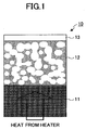
- FIG. 1 is a partial cross-sectional view of a fixing member according to an embodiment of the present invention.
- a fixing member 10 according to an embodiment of the present invention includes a metal roller 11, a silicon rubber layer 12, and a PFA layer 13, which are laminated onto each other.
- the silicon rubber layer 12 includes bubbles 12-2 corresponding to vacant spaces, which are continuous bubbles connected via bubble continuation parts 12-1, and carbon fiber 12-3.
- the heat from a heater (not shown) that is the heat source is transferred to the metal roller 11, and the heat from the metal roller 11 is transferred to the PFA layer 13 through the silicon rubber layer 12. Accordingly, heat is transferred to the toner as the PFA layer 13 contacts the toner, thereby fixing the toner.
- FIG. 2 is an enlarged view showing the relationship between the continuous bubble structure and the carbon fiber in the silicon rubber layer 12.
- the bubbles 12-2 adjacent to each other are connected at the bubble continuation parts 12-1, and therefore the gas inside the bubbles 12-2 can flow through the bubble continuation parts 12-1 when the bubbles 12-2 are deformed.
- FIG. 3 is an enlarged view of a silicon rubber layer having a single bubble structure, which corresponds to the comparative example 7 described below. As shown in FIG. 3 , a silicon rubber layer 20 having a single bubble structure includes bubbles 21 without the bubble continuation parts shown in FIG. 2 , and carbon fiber 22. Therefore, the gas cannot move among the vacant spaces, and consequently, the rigidness of the carbon fiber has an impact on the properties of the silicon rubber.
- An optimum product of the carbon fiber is pitch type milled carbon fiber, part number: XN-100-15M (150 microns), manufactured by Nippon Graphite Fiber Corporation.
- the thermal conductivity is assumed to be 500 W/mK.
- PAN type carbon fiber has a maximum thermal conductivity of 50 W/mK.
- a PFA tube has an adhesive layer formed inside in advance, and a cored bar with reinforcement projections ("ribs") is set at 0.5 mm inside the PFA tube.
- Unvulcanized silicon rubber including carbon fiber, pre-foamed particles, and a hardening agent, is infused as an infusion material in between the cored bar and the PFA tube. Then, secondary heating is performed to fix the infusion material.
- the pre-foamed agent is destroyed, and the peripheral portions of the carbon fiber are separated from the silicon rubber.
- glycerin, ethylene glycol, diethylene glycol, and triethylene glycol are used. These elements have a volatile effect, so that the spaces can be formed. It is also possible to prepare silicon unvulcanized liquid in the same manner as above, and apply/vulcanize this liquid onto the roller to form a fluorocarbon resin coat layer, or coat the roller with a fluorocarbon resin tube.
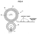
- FIG. 4 is a schematic cross-sectional view of a fixing device according to another invention, which includes the fixing member according to an embodiment of the present invention.
- a fixing device 1 according to another invention which includes the fixing member according to an embodiment of the present invention, has a heater 15 provided inside a roller-type cored bar 14, and a fixing member 10 according to an embodiment of the present invention is formed on the peripheral surface of the cored bar 14.
- a pressurizing roller 16 faces such a fixing roller.
- the pressurizing roller 16 is pressed against the fixing roller with a pressurizing mechanism 17 such as a spring. Accordingly, a recording medium on which an unfixed toner image is formed can be sandwiched and pressurized by the fixing roller and the pressurizing roller 16, so that the unfixed toner on the recording medium is fixed.
- FIG. 5 is a schematic cross-sectional view of an image forming apparatus according to another invention, including the fixing device according to an embodiment of the present invention.
- An image forming apparatus 100 according to another invention provided with the fixing device according to an embodiment of the present invention, includes a photoconductor 101 surrounded by a charger 102, a writing device 103, a developing unit 104, a transfer device 105, and a cleaning device 106.
- the charger 102 charges the photoconductor 101 to a positive polarity
- the writing device 103 writes optical information based on image information onto the charged photoconductor 101, thereby forming a visible latent image.
- the developing unit 104 uses toner that has been stirred and charged, to turn the visible latent image into a toner image.
- the toner image is transferred onto a recording medium by the transfer device 105.
- the unfixed toner that has been transferred onto the recording medium is fixed onto the recording medium, by conveying the recording medium carrying the unfixed toner to the nip portion between the fixing roller and the pressurizing roller in the fixing device 1, as described with reference to FIG. 4 .
- the fluorocarbon resin used in an embodiment of the present invention is preferably produced by burning to have good melted-state film-forming characteristics, and preferably has a relatively low melting point (preferably 250 °C through 300 °C).
- impalpable powder of low-molecular weight polytetrafluoroethylene (PTFE), tetrafluoroethylene-hexafluoropropylene copolymer (FEP), and tetrafluoroethylene-perfluoroalkylvinylether copolymer (PFA) may be selected.
- PTFE low-molecular weight polytetrafluoroethylene
- LUBRON registered trademark
- L-5 manufactured by Daikin Industries, Ltd.
- MP1100 manufactured by Daikin Industries, Ltd.
- MP1100 manufactured by Daikin Industries, Ltd.
- MP1100 manufactured by Daikin Industries, Ltd.
- TLP-10F-1 manufactured by DuPont-Mitsui Fluorochemicals, Co., Ltd.
- FEP tetrafluoroethylene-hexafluoropropylene copolymer
- MP-10 tetrafluoroethylene-perfluoroalkylvinylether copolymer
- MP102 manufactured by DuPont-Mitsui Fluorochemicals, Co., Ltd.
- products which have a low MFR (melted flow rate) and low fluidity are appropriate for the present invention, such as MP103, MP300 (manufactured by DuPont-Mitsui Fluorochemicals, Co., Ltd.) and AC-5600, AC5539 (manufactured by Daikin Industries, Ltd.).
- an example of the foaming agent is azobisisobutyronitrile (AIBN), and examples of the foamed particles are F-30, F-30VS, F-46, F-50D, and F-55D manufactured by Matsumoto Yushi-Seiyaku Co., Ltd.
- Examples of the pre-foamed particles are 100CA, 80CA, F-80ED, F-30E, F-50E, and F-80SDE manufactured by Matsumoto Yushi-Seiyaku Co., Ltd.
- Examples of the carbon fiber are PAN (polyacrylonitrile) type carbon fiber made from continuous acrylic fiber which is synthetic fiber, and pitch type carbon fiber made form coal tar and petroleum pitch.
- the PAN type carbon fiber is obtained by carbonizing a PAN precursor (polyacrylonitrile fiber), and has high strength and a high degree of elasticity.
- the pitch type carbon fiber is obtained by carbonizing a pitch precursor (pitch fiber obtained by using coal tar or petroleum heavy oil as the material). By changing the conditions of the manufacturing process, a wide range of properties can be achieved, from a low level of elasticity to a high level of elasticity/high strength.
- a super-high elasticity product may have high rigidity, excellent thermal conductivity, and electrical conductivity.
- this unvulcanized silicon rubber was infused as an infusion material between a PFA tube and a cored bar, where the cored bar with ribs corresponding to reinforcement projections was set at 0.5 mm inside the PFA tube which had an adhesive layer formed inside in advance.
- FIGS. 6B through 6D illustrate examples of cross-sectional views of the rib 31. Primary vulcanization was performed by heating this fixing roller at 120 °C, and then secondary vulcanization was performed by heating this fixing roller for four hours at 200 °C. Accordingly, the pre-foamed agent was destroyed, and the peripheral portions of the carbon fiber were separated from the silicon rubber.
- the fixing roller was fabricated by performing the above series of processes, so as to have an outer diameter of ⁇ 40 mm.
- the silicon rubber layer thickness was 3 mm.
- This fixing roller was set in a fixing unit of MF4570, which is a copier manufactured by Ricoh Co., Ltd., and the time (seconds) required for the temperature of the fixing roller to rise to 160 °C by heating it with a 1000 W halogen heater, was measured.
- the pressurizing roller instead of using silicon rubber of a standard product, silicon rubber similar to that of an embodiment of the present invention was used, without the carbon fiber. The temperature was measured by providing a thermocouple above the fixing roller.
- An infusion material having the same composition as that used for fabricating the roller was infused/vulcanized into a mold having a thickness of 2 mm and length and width of 100 mm.
- the expansion ratio was obtained from the volume, the weight, and the blending quantity of this sample.
- the rubber hardness of this sample was measured. Furthermore, the sample was cut into squares with sides of 50 mm. Three of these square pieces were stacked onto each other, and the compression set was measured at compression of 25% after being heated at 180 °C for 22 hours. The thickness of the cored bar was 0.4 mm with ribs.
- the rubber hardness was measured with the use of a micro rubber hardness scale MD-1: type A for general purpose rubber (JIS A approximate value). In the tables below, this is indicated as rubber hardness (MD-1).
- the carbon fiber was heated in air at 600 °C for two hours.
- comparative examples A-5 and A-6 glass fiber was used.
- the fiber was 06MW2-20 manufactured by ASAHI FIBER GLASS Co., Ltd., having a length of 100 ⁇ m through 300 ⁇ m, without a primer.
- 20MH2-20 was used, which is a glass fiber similar to the above, having a length of 100 ⁇ m through 300 ⁇ m, and treated with a silane-type primer.
- FIG. 7 is a cross-sectional view of carbon fiber cut with a razor blade, which has not been heat-treated. The linear, shining parts are the carbon fibers, which are separated from the silicon rubber, and are thus visible.
- FIG. 8 is a cross-sectional view of carbon fiber cut with a razor blade, which has been heated in air at 600 °C for two hours. Silicon rubber is adhering around the carbon fibers. The carbon fibers are not very visible because the parts of the silicon rubber have been cut. As described above, it can be obviously confirmed that there are significant non-adhering portions around the carbon fibers.
- the rubber hardness was low, and the compression set was also low. Furthermore, the startup time of the fixing device was less than or equal to 30 seconds. As for comparative examples B-1 and B-3, the startup time was delayed, and in comparative example B-2, the compression set was extremely high and the heating roller was deformed after maintaining the heating/pressurizing state at 160 °C for 100 hours.
- This fixing roller was set in a fixing unit of MF4570, which is a copier manufactured by Ricoh Co., Ltd., and the time (seconds) required for the temperature of the fixing roller to rise to 160 °C by heating it with a 1000 W halogen heater, was measured.
- the blending was performed in units of parts by weight; as for F-30, the expansion ratio of bubbles formed after foaming was converted into volume.
- the wall thickness of the cored bar was 0.4 mm with ribs.
- the compression set can be made extremely small by performing the primary vulcanization so that the rubber is foamed and fixed, and then performing the secondary vulcanization.
- the roller of practical example B-2 was set in a fixing unit in MF4570 manufactured by Ricoh Co., Ltd. Then, 10,000 sheets of solid black images produced by imagio MP C4500 manufactured by Ricoh Co., Ltd., were passed through the fixing unit. Then, examinations were made as to the amount of toner adhering to the roller surface, and whether any paper sheets adhered around the roller, as shown in Table 6. Accordingly, it was found that the roller is effective when the surface roughness Rz (ten point average roughness: JIS (Japanese Industrial Standards) B0601-1994) is less than or equal to 5 ⁇ m.
- Rz ten point average roughness: JIS (Japanese Industrial Standards) B0601-1994
- a sheet passing test was performed for an unfixed image created with IPSIO Color 8100 manufactured by Ricoh Co., Ltd.
- the toner used in IPSIO Color 8100 has insufficient mold releasing properties, and therefore there was provided an oil applying member impregnated with silicon oil to apply silicon oil onto the fixing roller.
- 10,000 sheets of solid black images were passed through the IPSIO Color 8100, and the extent of toner adhering to the roller surface was examined. No significant amount of toner was observed, and the roller appeared to be in a regular state. However, in cases where the oil applying member was not provided, a significant amount of toner adhered to the roller at the 6,000th sheet.
- a roller of practical example F was made by making the roller of practical example A-1 have a surface roughness Rz of less than or equal to 2 ⁇ m.
- a fixing test machine including the fixing unit of MF4570 was fabricated, and unfixed images produced by imagio MP C4500 were passed through the roller, with different pressures. As shown in Table 7, when the pressure was less than or equal to 2.9 N/cm 2 , the fixing properties were very poor, and when the pressure was greater than or equal to 19.6 N/cm 2 , toner adhered to the fixing roller. Sheets adhered around the fixing roller when even more toner adhered to the fixing roller. When the pressure was less than or equal to 39.2 N/cm 2 , the sheets did not adhere around the fixing roller.
- the carbon fiber acts as a path for transferring heat.
- the carbon fiber is not firmly fixed and can therefore easily deform by slipping. Accordingly, the fixing member is prevented from being destroyed due to concentration of stress on the silicon rubber, and the compression set can be decreased.
- the rigidity of the carbon fiber and the gas flowing among the vacant spaces can be increased, so that a fixing member can be provided, which has low heat capacity (low density), high thermal conductivity, and a low rubber hardness.
- the fixing member can have a sufficient level of thermal conductivity.
- the fixing member can be easily manufactured, and the compression set can be decreased.
- an expansion ratio of the fixing member is greater than or equal to 1.5 and less than or equal to 3.0. If the expansion ratio were less than 1.5, the heat capacity would be large, and therefore the fixing member could not be made thick enough to attain a large nip. If the expansion ratio were to exceed 3.0, the walls would be extremely thin, and therefore the strength would decrease and the compression set would increase. Accordingly, when the fixing member has an expansion ratio falling in a range of greater than or equal to 1.5 and less than or equal to 3.0, low heat capacity and high strength can be attained, so that the fixing operation can be properly performed.
- the cored bar of the fixing rotational body is the first component to be heated by the heater in the roller, and therefore heat capacity is an important factor. If the cored bar has a thickness of less than or equal to 0.5 mm, the fixing device can start up within 10-odd seconds. However, the strength with respect to flexure will decrease. For this reason, projections having circling shapes are formed on the inner surface of the cored bar for reinforcement. Accordingly, a fixing device that can start up at high speed is provided.
- the fixing rotational body is applicable to a durable induction heater, with which parting properties can be attained even with respect to oil-less toner.
- the roller has good thermal conductivity and low rubber hardness so that heat can be uniformly transferred, and the fixing member has high film strength, thereby providing a fixing device and a image forming apparatus that are highly reliable and that have good energy efficiency.
Landscapes
- Engineering & Computer Science (AREA)
- General Engineering & Computer Science (AREA)
- Mechanical Engineering (AREA)
- Physics & Mathematics (AREA)
- General Physics & Mathematics (AREA)
- Rolls And Other Rotary Bodies (AREA)
- Fixing For Electrophotography (AREA)
Claims (11)
- Fixierglied (10), das auf einem drehbaren bzw. rotierenden Fixierkörper enthalten ist, der eine Heizquelle (15) darin eingebaut hat, wobei:der drehbare bzw. rotierende Fixierkörper konfiguriert ist, um unfixierten Toner auf einem Aufzeichnungsmedium zu fixieren, während das Aufzeichnungsmedium, das den unfixierten Toner trägt, durch einen Klemmstellenabschnitt bzw. Walzenspaltabschnitt hindurchgeht, der zwischen dem drehbaren bzw. rotierenden Fixierkörper und einer Druckbeaufschlagungseinheit (16) gebildet ist, die in Druckkontakt mit dem drehbaren bzw. rotierenden Fixierkörper kommt, und zwar über bzw. via das Aufzeichnungsmedium;und wobei das Fixierglied (10) aus Silikongummi (12) hergestellt bzw. geschaffen ist, der Carbonfasern bzw. Kohlenstofffasern (12-3) aufweist, wobei Blasen bzw. Lunker (12-2) in dem Silikongummi (12) gebildet sind;dadurch gekennzeichnet, dass:die Carbonfasern bzw. Kohlenstofffasern (12-3), die in dem Silikongummi (12) enthalten sind, in Kontakt miteinander sind, so dass die Carbonfasern bzw. Kohlenstofffasern (12-3) als Pfade bzw. Bahnen zum Übertragen von Wärme wirken; undwobei die Carbonfasern bzw. Kohlenstofffasern (12-3) in dem Silikongummi (12) nicht anhaftende Abschnitte aufweisen, die in leere bzw. vakante Räume vorstehen bzw. ragen, welche kontinuierliche bzw. zusammenhängende Blasen bzw. Lunker sind, die über bzw. via Blasen- bzw. Lunkerfortsetzungsteile verbunden sind, und Carbonfasern bzw. Kohlenstofffasern aufweisen, so dass das Gas innerhalb der Blasen bzw. Lunker durch die Blasen- bzw. Lunkerfortsetzungsteile strömen kann, wenn die Blasen bzw. Lunker verformt bzw. in der Form verändert werden.
- Fixierglied (10) gemäß Anspruch 1, wobei die Carbonfasern bzw. Kohlenstofffasern (12-3) Carbonfasern bzw. Kohlenstofffasern des Pitch-Typs bzw. Pech-Typs sind.
- Verfahren des Herstellens eines Fixierglieds (10), das auf einem drehbaren bzw. rotierenden Fixierkörper enthalten ist, der eine Heizquelle (15) darin eingebaut hat, wobei der drehbare bzw. rotierende Fixierkörper konfiguriert ist, um unfixierten Toner auf einem Aufzeichnungsmedium zu fixieren, während das Aufzeichnungsmedium, das den unfixierten Toner trägt, durch einen Klemmstellenabschnitt bzw. Walzenspaltabschnitt hindurchgeht, der zwischen dem drehbaren bzw. rotierenden Fixierkörper und einer Druckbeaufschlagungseinheit (16) gebildet ist, die in Druckkontakt mit dem drehbaren bzw. rotierenden Fixierkörper kommt, und zwar über bzw. via das Aufzeichnungsmedium, wobei das Verfahren gekennzeichnet ist durch Aufweisen:einen Schritt des Enthaltens eines Schaummittels bzw. Schaumbildners oder geschäumter Partikel bzw. Teilchen in unvulkanisiertem bzw. nicht vulkanisiertem Silikongummi, einen Schritt des Enthaltens von Carbonfasern bzw. Kohlenstofffasern in dem unvulkanisierten bzw. nicht vulkanisierten Silikongummi, und einen Schritt des Durchführens primärer Vulkanisation und einer Schaumbildungstätigkeit bzw. Schaumbildungsfunktion auf bzw. in dem unvulkanisierten bzw. nicht vulkanisierten Silikongummi; odereinen Schritt des Enthaltens von Carbonfasern bzw. Kohlenstofffasern und vorgeschäumten Partikeln bzw. Teilchen in unvulkanisiertem bzw. nicht vulkanisiertem Silikongummi, und einen Schritt des Durchführens primärer Vulkanisation auf bzw. in dem unvulkanisierten bzw. nicht vulkanisierten Silikongummi; undeinen Schritt des Durchführens sekundärer Vulkanisation auf bzw. in dem Silikongummi, welcher die primäre Vulkanisation durchlaufen hat, wobei das Verfahren derart ist, dass die Carbonfasern bzw. Kohlenstoffasern (12-3), die in dem Silikongummi von dem auf diese Weise hergestellten Fixierglied (10) enthalten sind, in Kontakt miteinander sind, so dass die Carbonfasern bzw. Kohlenstofffasern (12-3) als Pfade bzw. Bahnen zum Übertragen von Wärme wirken, und wobei die Carbonfasern bzw. Kohlenstofffasern (12-13) in dem Silikongummi (12) nicht anhaftende Abschnitte aufweisen, die in leere bzw. vakante Räume vorstehen bzw. ragen, welche kontinuierliche bzw. zusammenhängende Blasen bzw. Lunker sind, die über bzw. via Blasen- bzw. Lunkerfortsetzungsteile verbunden sind, und Carbonfasern bzw. Kohlenstofffasern aufweisen, so dass das Gas innerhalb der Blasen bzw. Lunker durch die Blasen- bzw. Lunkerfortsetzungsteile strömen kann, wenn die Blasen bzw. Lunker verformt bzw. in der Form verändert werden.
- Verfahren des Herstellens des Fixiergliedes (10) gemäß Anspruch 3, wobei:die Carbonfasern bzw. Kohlenstofffasern (12-3) Carbonfasern bzw. Kohlenstofffasern des Pitch-Typs bzw. Pech-Typs sind.
- Verfahren des Herstellens des Fixiergliedes (10) gemäß Anspruch 3, wobei:ein Ausdehnungsverhältnis von dem Fixierglied (10) größer als oder gleich 1,5 und kleiner als oder gleich 3,0 ist.
- Drehbarer bzw. rotierender Fixierkörper, der das Fixierglied (10) gemäß Anspruch 1 oder 2, oder das Fixierglied (10) aufweist, das durch das Verfahren gemäß irgendeinem der Ansprüche 3 bis 5 hergestellt wird.
- Drehbarer bzw. rotierender Fixierkörper gemäß Anspruch 6, aufweisend:eine ausgehöhlte Stange bzw. Hohlkörper, welche bzw. welcher eine Metallrolle bzw. Metallwalze (14) ist, wobei:die ausgehöhlte Stange bzw. der Hohlkörper eine Dicke hat, die größer als oder gleich 0,25 mm und kleiner als oder gleich 0,5 mm ist; undmehrere Vorsprünge, die runde bzw. kreisförmige Formen haben, sind auf einer inneren Oberfläche von der ausgehöhlten Stange bzw. dem Hohlkörper gebildet.
- Drehbarer bzw. rotierender Fixierkörper gemäß Anspruch 6 oder 7, aufweisend:eine Schicht, die aus Fluorpolymer hergestellt bzw. erzeugt wird, welche auf einer äußersten Oberfläche von dem drehbaren bzw. rotierenden Fixierkörper zur Verfügung gestellt wird.
- Drehbarer bzw. rotierender Fixierkörper gemäß irgendeinem der Ansprüche 6 bis 8, wobei:der drehbare bzw. rotierende Fixierkörper eine Oberflächenrauheit Rz (durchschnittliche Zehnpunktrauheit) von weniger als oder gleich 5µm hat.
- Fixiervorrichtung, aufweisend den drehbaren bzw. rotierenden Fixierkörper gemäß irgendeinem der Ansprüche 6 bis 9.
- Bilderzeugungsapparat, aufweisend:die Fixiervorrichtung gemäß Anspruch 10; undeine Bilderzeugungseinheit, wobei:ein Tonerbild auf einem Aufzeichnungsmedium in der Bilderzeugungseinheit gebildet bzw. erzeugt wird; undwobei das Tonerbild auf dem Aufzeichnungsmedium in der Fixiervorrichtung fixiert wird.
Applications Claiming Priority (2)
| Application Number | Priority Date | Filing Date | Title |
|---|---|---|---|
| JP2008072727A JP4988633B2 (ja) | 2008-03-21 | 2008-03-21 | 定着部材、定着部材の製造方法、定着用回転体、定着装置及び画像形成装置 |
| PCT/JP2009/055384 WO2009116607A1 (en) | 2008-03-21 | 2009-03-12 | Fixing member, manufacturing method of fixing member, rotational body of fixing member, fixing device, and image forming apparatus |
Publications (3)
| Publication Number | Publication Date |
|---|---|
| EP2255255A1 EP2255255A1 (de) | 2010-12-01 |
| EP2255255A4 EP2255255A4 (de) | 2013-06-05 |
| EP2255255B1 true EP2255255B1 (de) | 2016-05-25 |
Family
ID=41091005
Family Applications (1)
| Application Number | Title | Priority Date | Filing Date |
|---|---|---|---|
| EP09721955.4A Not-in-force EP2255255B1 (de) | 2008-03-21 | 2009-03-12 | Befestigungselement, verfahren zur herstellung des befestigungselements, drehkörper für das befestigungselement, befestigungsvorrichtung und bilderzeugungsvorrichtung |
Country Status (6)
| Country | Link |
|---|---|
| US (1) | US8369764B2 (de) |
| EP (1) | EP2255255B1 (de) |
| JP (1) | JP4988633B2 (de) |
| KR (1) | KR101180014B1 (de) |
| CN (1) | CN101978325B (de) |
| WO (1) | WO2009116607A1 (de) |
Families Citing this family (14)
| Publication number | Priority date | Publication date | Assignee | Title |
|---|---|---|---|---|
| JP5822559B2 (ja) * | 2010-07-15 | 2015-11-24 | キヤノン株式会社 | 加圧ローラ、その加圧ローラを用いた像加熱装置、及びその加圧ローラの製造方法 |
| JP2014134696A (ja) * | 2013-01-11 | 2014-07-24 | Ricoh Co Ltd | 電子写真定着用定着部材、定着装置及び画像形成装置 |
| JP2014142406A (ja) * | 2013-01-22 | 2014-08-07 | Ricoh Co Ltd | 押圧部材、定着装置及び画像形成装置 |
| JP6015488B2 (ja) * | 2013-02-22 | 2016-10-26 | 株式会社リコー | 定着部材、定着装置、及び画像形成装置 |
| JP6155718B2 (ja) * | 2013-03-14 | 2017-07-05 | 株式会社リコー | 電子写真の定着装置、画像形成装置、定着方法 |
| JP6269030B2 (ja) | 2013-07-17 | 2018-01-31 | 株式会社リコー | 定着部材、定着装置、及び画像形成装置 |
| JP6357875B2 (ja) | 2013-07-26 | 2018-07-18 | 株式会社リコー | 定着部材、定着装置及び画像形成装置 |
| JP5849128B2 (ja) * | 2014-06-20 | 2016-01-27 | 昭和電線デバイステクノロジー株式会社 | 熱定着用ゴムローラの製造方法 |
| JP6570350B2 (ja) * | 2014-07-16 | 2019-09-04 | キヤノン株式会社 | 弾性ローラ及び定着装置 |
| JP6312544B2 (ja) * | 2014-07-16 | 2018-04-18 | キヤノン株式会社 | ニップ部形成部材、画像加熱装置、及びニップ部形成部材の製造方法 |
| JP6531891B2 (ja) * | 2014-10-09 | 2019-06-19 | シンジーテック株式会社 | 定着・加圧ロールの製造方法及び定着装置の製造方法 |
| JP2016184085A (ja) * | 2015-03-26 | 2016-10-20 | 富士ゼロックス株式会社 | 定着用加圧部材、定着装置、及び画像形成装置 |
| KR102237471B1 (ko) * | 2019-10-07 | 2021-04-06 | 재단법인 자동차융합기술원 | 실시간 전기 전도도 측정 시스템 |
| JP2024158347A (ja) * | 2023-04-27 | 2024-11-08 | 株式会社リコー | 定着装置及び画像形成装置 |
Family Cites Families (21)
| Publication number | Priority date | Publication date | Assignee | Title |
|---|---|---|---|---|
| JPH04166970A (ja) | 1990-10-31 | 1992-06-12 | Ricoh Co Ltd | 定着装置 |
| JP3658305B2 (ja) * | 1999-09-30 | 2005-06-08 | キヤノン株式会社 | 加熱装置及び画像形成装置 |
| US6459878B1 (en) | 1999-09-30 | 2002-10-01 | Canon Kabushiki Kaisha | Heating assembly, image-forming apparatus, and process for producing silicone rubber sponge and roller |
| JP2002003732A (ja) | 2000-06-26 | 2002-01-09 | Sekisui Chem Co Ltd | 熱伝導性樹脂組成物及び樹脂シート |
| JP3969942B2 (ja) * | 2000-09-01 | 2007-09-05 | キヤノン株式会社 | ローラとその製造方法、及び加熱定着装置 |
| EP1202132B1 (de) | 2000-10-30 | 2005-04-20 | Ricoh Company, Ltd. | Fixierwalze, diese verwendendes Fixiergerät, sowie dieses Fixiergerät verwendendes Bilderzeugungsgerät |
| JP2002128931A (ja) | 2000-10-30 | 2002-05-09 | Sekisui Chem Co Ltd | 熱伝導性樹脂シート |
| JP2006209156A (ja) * | 2000-10-30 | 2006-08-10 | Ricoh Co Ltd | 定着装置および画像形成装置 |
| JP2002317064A (ja) | 2001-04-20 | 2002-10-31 | Sekisui Chem Co Ltd | 熱伝導材 |
| JP2003098881A (ja) * | 2001-09-21 | 2003-04-04 | Ricoh Co Ltd | 定着用部材及びその製造方法並びにそれを有する画像形成装置 |
| JP4165863B2 (ja) * | 2002-08-23 | 2008-10-15 | キヤノン株式会社 | 半導電性ローラ |
| JP2004361839A (ja) * | 2003-06-06 | 2004-12-24 | Oki Data Corp | 定着装置 |
| JP2005084077A (ja) * | 2003-09-04 | 2005-03-31 | Fuji Xerox Co Ltd | 熱伝導部材および画像形成装置 |
| JP2005292218A (ja) * | 2004-03-31 | 2005-10-20 | Arai Pump Mfg Co Ltd | 定着器用ローラ |
| JP2006133576A (ja) | 2004-11-08 | 2006-05-25 | Canon Inc | 熱伝導弾性部材および定着部材 |
| JP2007047321A (ja) * | 2005-08-08 | 2007-02-22 | Ricoh Co Ltd | ローラ芯金及びその製造方法、定着ローラ、定着装置、及び、それを有する画像形成装置 |
| JP2007139847A (ja) | 2005-11-15 | 2007-06-07 | Ricoh Co Ltd | 加熱部材、定着装置及び画像形成装置 |
| JP5080003B2 (ja) * | 2005-12-20 | 2012-11-21 | シンジーテック株式会社 | スポンジロール及びその製造方法 |
| JP5071912B2 (ja) * | 2006-04-21 | 2012-11-14 | 株式会社リコー | 定着ローラ、定着装置及び画像形成装置 |
| JP5072381B2 (ja) | 2007-02-07 | 2012-11-14 | 株式会社リコー | 定着装置及び画像形成装置 |
| JP5233129B2 (ja) | 2007-02-15 | 2013-07-10 | 株式会社リコー | 加熱ローラ、定着装置及び画像形成装置 |
-
2008
- 2008-03-21 JP JP2008072727A patent/JP4988633B2/ja not_active Expired - Fee Related
-
2009
- 2009-03-12 CN CN200980109624.4A patent/CN101978325B/zh not_active Expired - Fee Related
- 2009-03-12 US US12/735,767 patent/US8369764B2/en not_active Expired - Fee Related
- 2009-03-12 EP EP09721955.4A patent/EP2255255B1/de not_active Not-in-force
- 2009-03-12 KR KR1020107020801A patent/KR101180014B1/ko not_active Expired - Fee Related
- 2009-03-12 WO PCT/JP2009/055384 patent/WO2009116607A1/en not_active Ceased
Also Published As
| Publication number | Publication date |
|---|---|
| US20100310290A1 (en) | 2010-12-09 |
| KR20100119572A (ko) | 2010-11-09 |
| KR101180014B1 (ko) | 2012-09-06 |
| CN101978325B (zh) | 2013-05-15 |
| EP2255255A1 (de) | 2010-12-01 |
| JP2009229616A (ja) | 2009-10-08 |
| EP2255255A4 (de) | 2013-06-05 |
| JP4988633B2 (ja) | 2012-08-01 |
| WO2009116607A1 (en) | 2009-09-24 |
| CN101978325A (zh) | 2011-02-16 |
| US8369764B2 (en) | 2013-02-05 |
Similar Documents
| Publication | Publication Date | Title |
|---|---|---|
| EP2255255B1 (de) | Befestigungselement, verfahren zur herstellung des befestigungselements, drehkörper für das befestigungselement, befestigungsvorrichtung und bilderzeugungsvorrichtung | |
| US9229396B1 (en) | Fuser member | |
| US10228644B2 (en) | Addition-curable liquid silicone rubber mixture, electrophotographic member, method for producing the same, and fixing apparatus | |
| JP5240546B2 (ja) | 定着用回転体と定着装置と画像形成装置及び定着用回転体の製造方法 | |
| EP2075646A1 (de) | Presswalze und herstellungsverfahren dafür | |
| CN108345200B (zh) | 电子照相用构件、电子照相用构件的制造方法和定影设备 | |
| US20110085831A1 (en) | Fuser for an Image-Forming Apparatus and Method of Using Same | |
| JP5072381B2 (ja) | 定着装置及び画像形成装置 | |
| US10809654B2 (en) | Pressure roller for fixing apparatus, fixing apparatus and image forming apparatus | |
| US20150153687A1 (en) | Fuser member | |
| US10042298B2 (en) | Film and image heating device using film | |
| JP5061255B2 (ja) | 定着部材の製造方法 | |
| US20130122286A1 (en) | Fuser member | |
| US9195191B2 (en) | Fixing member for electrophotographic fixing, fixing device, and image forming apparatus | |
| US11624994B2 (en) | Fixing belt and fixing apparatus | |
| US9244407B2 (en) | Fixing member with alkali metal ion, image heat fixing apparatus, and electrophotographic image forming apparatus | |
| EP2770376A2 (de) | Befestigungselement, Befestigungsvorrichtung sowie Bildgebungsvorrichtung | |
| JP6192443B2 (ja) | 定着フィルム及びそれを備えた定着装置 | |
| JP7621767B2 (ja) | 定着装置に用いられるローラ、このローラを搭載する定着装置、及び画像形成装置 | |
| JP2012068318A (ja) | 画像形成装置の定着用のベルトまたはロール | |
| US20150293479A1 (en) | Fuser member | |
| JP2008197581A (ja) | 加熱部材、定着装置、画像形成装置及び加熱部材の製造方法 |
Legal Events
| Date | Code | Title | Description |
|---|---|---|---|
| PUAI | Public reference made under article 153(3) epc to a published international application that has entered the european phase |
Free format text: ORIGINAL CODE: 0009012 |
|
| 17P | Request for examination filed |
Effective date: 20100825 |
|
| AK | Designated contracting states |
Kind code of ref document: A1 Designated state(s): AT BE BG CH CY CZ DE DK EE ES FI FR GB GR HR HU IE IS IT LI LT LU LV MC MK MT NL NO PL PT RO SE SI SK TR |
|
| AX | Request for extension of the european patent |
Extension state: AL BA RS |
|
| DAX | Request for extension of the european patent (deleted) | ||
| A4 | Supplementary search report drawn up and despatched |
Effective date: 20130507 |
|
| RIC1 | Information provided on ipc code assigned before grant |
Ipc: F16C 13/00 20060101ALI20130429BHEP Ipc: G03G 15/20 20060101AFI20130429BHEP |
|
| GRAP | Despatch of communication of intention to grant a patent |
Free format text: ORIGINAL CODE: EPIDOSNIGR1 |
|
| INTG | Intention to grant announced |
Effective date: 20151221 |
|
| GRAS | Grant fee paid |
Free format text: ORIGINAL CODE: EPIDOSNIGR3 |
|
| GRAA | (expected) grant |
Free format text: ORIGINAL CODE: 0009210 |
|
| AK | Designated contracting states |
Kind code of ref document: B1 Designated state(s): AT BE BG CH CY CZ DE DK EE ES FI FR GB GR HR HU IE IS IT LI LT LU LV MC MK MT NL NO PL PT RO SE SI SK TR |
|
| REG | Reference to a national code |
Ref country code: GB Ref legal event code: FG4D |
|
| REG | Reference to a national code |
Ref country code: CH Ref legal event code: EP |
|
| REG | Reference to a national code |
Ref country code: IE Ref legal event code: FG4D Ref country code: AT Ref legal event code: REF Ref document number: 802788 Country of ref document: AT Kind code of ref document: T Effective date: 20160615 |
|
| REG | Reference to a national code |
Ref country code: DE Ref legal event code: R096 Ref document number: 602009038849 Country of ref document: DE |
|
| REG | Reference to a national code |
Ref country code: LT Ref legal event code: MG4D |
|
| REG | Reference to a national code |
Ref country code: NL Ref legal event code: MP Effective date: 20160525 |
|
| PG25 | Lapsed in a contracting state [announced via postgrant information from national office to epo] |
Ref country code: FI Free format text: LAPSE BECAUSE OF FAILURE TO SUBMIT A TRANSLATION OF THE DESCRIPTION OR TO PAY THE FEE WITHIN THE PRESCRIBED TIME-LIMIT Effective date: 20160525 Ref country code: LT Free format text: LAPSE BECAUSE OF FAILURE TO SUBMIT A TRANSLATION OF THE DESCRIPTION OR TO PAY THE FEE WITHIN THE PRESCRIBED TIME-LIMIT Effective date: 20160525 Ref country code: NO Free format text: LAPSE BECAUSE OF FAILURE TO SUBMIT A TRANSLATION OF THE DESCRIPTION OR TO PAY THE FEE WITHIN THE PRESCRIBED TIME-LIMIT Effective date: 20160825 Ref country code: NL Free format text: LAPSE BECAUSE OF FAILURE TO SUBMIT A TRANSLATION OF THE DESCRIPTION OR TO PAY THE FEE WITHIN THE PRESCRIBED TIME-LIMIT Effective date: 20160525 |
|
| REG | Reference to a national code |
Ref country code: AT Ref legal event code: MK05 Ref document number: 802788 Country of ref document: AT Kind code of ref document: T Effective date: 20160525 |
|
| PG25 | Lapsed in a contracting state [announced via postgrant information from national office to epo] |
Ref country code: PT Free format text: LAPSE BECAUSE OF FAILURE TO SUBMIT A TRANSLATION OF THE DESCRIPTION OR TO PAY THE FEE WITHIN THE PRESCRIBED TIME-LIMIT Effective date: 20160926 Ref country code: SE Free format text: LAPSE BECAUSE OF FAILURE TO SUBMIT A TRANSLATION OF THE DESCRIPTION OR TO PAY THE FEE WITHIN THE PRESCRIBED TIME-LIMIT Effective date: 20160525 Ref country code: ES Free format text: LAPSE BECAUSE OF FAILURE TO SUBMIT A TRANSLATION OF THE DESCRIPTION OR TO PAY THE FEE WITHIN THE PRESCRIBED TIME-LIMIT Effective date: 20160525 Ref country code: GR Free format text: LAPSE BECAUSE OF FAILURE TO SUBMIT A TRANSLATION OF THE DESCRIPTION OR TO PAY THE FEE WITHIN THE PRESCRIBED TIME-LIMIT Effective date: 20160826 Ref country code: LV Free format text: LAPSE BECAUSE OF FAILURE TO SUBMIT A TRANSLATION OF THE DESCRIPTION OR TO PAY THE FEE WITHIN THE PRESCRIBED TIME-LIMIT Effective date: 20160525 Ref country code: HR Free format text: LAPSE BECAUSE OF FAILURE TO SUBMIT A TRANSLATION OF THE DESCRIPTION OR TO PAY THE FEE WITHIN THE PRESCRIBED TIME-LIMIT Effective date: 20160525 |
|
| PG25 | Lapsed in a contracting state [announced via postgrant information from national office to epo] |
Ref country code: IT Free format text: LAPSE BECAUSE OF FAILURE TO SUBMIT A TRANSLATION OF THE DESCRIPTION OR TO PAY THE FEE WITHIN THE PRESCRIBED TIME-LIMIT Effective date: 20160525 |
|
| PG25 | Lapsed in a contracting state [announced via postgrant information from national office to epo] |
Ref country code: SK Free format text: LAPSE BECAUSE OF FAILURE TO SUBMIT A TRANSLATION OF THE DESCRIPTION OR TO PAY THE FEE WITHIN THE PRESCRIBED TIME-LIMIT Effective date: 20160525 Ref country code: RO Free format text: LAPSE BECAUSE OF FAILURE TO SUBMIT A TRANSLATION OF THE DESCRIPTION OR TO PAY THE FEE WITHIN THE PRESCRIBED TIME-LIMIT Effective date: 20160525 Ref country code: EE Free format text: LAPSE BECAUSE OF FAILURE TO SUBMIT A TRANSLATION OF THE DESCRIPTION OR TO PAY THE FEE WITHIN THE PRESCRIBED TIME-LIMIT Effective date: 20160525 Ref country code: DK Free format text: LAPSE BECAUSE OF FAILURE TO SUBMIT A TRANSLATION OF THE DESCRIPTION OR TO PAY THE FEE WITHIN THE PRESCRIBED TIME-LIMIT Effective date: 20160525 Ref country code: CZ Free format text: LAPSE BECAUSE OF FAILURE TO SUBMIT A TRANSLATION OF THE DESCRIPTION OR TO PAY THE FEE WITHIN THE PRESCRIBED TIME-LIMIT Effective date: 20160525 |
|
| PG25 | Lapsed in a contracting state [announced via postgrant information from national office to epo] |
Ref country code: BE Free format text: LAPSE BECAUSE OF FAILURE TO SUBMIT A TRANSLATION OF THE DESCRIPTION OR TO PAY THE FEE WITHIN THE PRESCRIBED TIME-LIMIT Effective date: 20160525 Ref country code: AT Free format text: LAPSE BECAUSE OF FAILURE TO SUBMIT A TRANSLATION OF THE DESCRIPTION OR TO PAY THE FEE WITHIN THE PRESCRIBED TIME-LIMIT Effective date: 20160525 Ref country code: PL Free format text: LAPSE BECAUSE OF FAILURE TO SUBMIT A TRANSLATION OF THE DESCRIPTION OR TO PAY THE FEE WITHIN THE PRESCRIBED TIME-LIMIT Effective date: 20160525 |
|
| REG | Reference to a national code |
Ref country code: DE Ref legal event code: R097 Ref document number: 602009038849 Country of ref document: DE |
|
| REG | Reference to a national code |
Ref country code: FR Ref legal event code: PLFP Year of fee payment: 9 |
|
| PLBE | No opposition filed within time limit |
Free format text: ORIGINAL CODE: 0009261 |
|
| STAA | Information on the status of an ep patent application or granted ep patent |
Free format text: STATUS: NO OPPOSITION FILED WITHIN TIME LIMIT |
|
| 26N | No opposition filed |
Effective date: 20170228 |
|
| PG25 | Lapsed in a contracting state [announced via postgrant information from national office to epo] |
Ref country code: SI Free format text: LAPSE BECAUSE OF FAILURE TO SUBMIT A TRANSLATION OF THE DESCRIPTION OR TO PAY THE FEE WITHIN THE PRESCRIBED TIME-LIMIT Effective date: 20160525 |
|
| REG | Reference to a national code |
Ref country code: CH Ref legal event code: PL |
|
| PG25 | Lapsed in a contracting state [announced via postgrant information from national office to epo] |
Ref country code: MC Free format text: LAPSE BECAUSE OF FAILURE TO SUBMIT A TRANSLATION OF THE DESCRIPTION OR TO PAY THE FEE WITHIN THE PRESCRIBED TIME-LIMIT Effective date: 20160525 |
|
| REG | Reference to a national code |
Ref country code: IE Ref legal event code: MM4A |
|
| PG25 | Lapsed in a contracting state [announced via postgrant information from national office to epo] |
Ref country code: LU Free format text: LAPSE BECAUSE OF NON-PAYMENT OF DUE FEES Effective date: 20170312 |
|
| PG25 | Lapsed in a contracting state [announced via postgrant information from national office to epo] |
Ref country code: LI Free format text: LAPSE BECAUSE OF NON-PAYMENT OF DUE FEES Effective date: 20170331 Ref country code: CH Free format text: LAPSE BECAUSE OF NON-PAYMENT OF DUE FEES Effective date: 20170331 Ref country code: IE Free format text: LAPSE BECAUSE OF NON-PAYMENT OF DUE FEES Effective date: 20170312 |
|
| REG | Reference to a national code |
Ref country code: FR Ref legal event code: PLFP Year of fee payment: 10 |
|
| PG25 | Lapsed in a contracting state [announced via postgrant information from national office to epo] |
Ref country code: MT Free format text: LAPSE BECAUSE OF NON-PAYMENT OF DUE FEES Effective date: 20170312 |
|
| PG25 | Lapsed in a contracting state [announced via postgrant information from national office to epo] |
Ref country code: HU Free format text: LAPSE BECAUSE OF FAILURE TO SUBMIT A TRANSLATION OF THE DESCRIPTION OR TO PAY THE FEE WITHIN THE PRESCRIBED TIME-LIMIT; INVALID AB INITIO Effective date: 20090312 |
|
| PG25 | Lapsed in a contracting state [announced via postgrant information from national office to epo] |
Ref country code: BG Free format text: LAPSE BECAUSE OF FAILURE TO SUBMIT A TRANSLATION OF THE DESCRIPTION OR TO PAY THE FEE WITHIN THE PRESCRIBED TIME-LIMIT Effective date: 20160525 |
|
| PG25 | Lapsed in a contracting state [announced via postgrant information from national office to epo] |
Ref country code: CY Free format text: LAPSE BECAUSE OF NON-PAYMENT OF DUE FEES Effective date: 20160525 |
|
| PG25 | Lapsed in a contracting state [announced via postgrant information from national office to epo] |
Ref country code: MK Free format text: LAPSE BECAUSE OF FAILURE TO SUBMIT A TRANSLATION OF THE DESCRIPTION OR TO PAY THE FEE WITHIN THE PRESCRIBED TIME-LIMIT Effective date: 20160525 |
|
| PG25 | Lapsed in a contracting state [announced via postgrant information from national office to epo] |
Ref country code: TR Free format text: LAPSE BECAUSE OF FAILURE TO SUBMIT A TRANSLATION OF THE DESCRIPTION OR TO PAY THE FEE WITHIN THE PRESCRIBED TIME-LIMIT Effective date: 20160525 |
|
| PGFP | Annual fee paid to national office [announced via postgrant information from national office to epo] |
Ref country code: GB Payment date: 20200323 Year of fee payment: 12 Ref country code: DE Payment date: 20200320 Year of fee payment: 12 |
|
| PGFP | Annual fee paid to national office [announced via postgrant information from national office to epo] |
Ref country code: FR Payment date: 20200320 Year of fee payment: 12 |
|
| PG25 | Lapsed in a contracting state [announced via postgrant information from national office to epo] |
Ref country code: IS Free format text: LAPSE BECAUSE OF FAILURE TO SUBMIT A TRANSLATION OF THE DESCRIPTION OR TO PAY THE FEE WITHIN THE PRESCRIBED TIME-LIMIT Effective date: 20160925 |
|
| REG | Reference to a national code |
Ref country code: DE Ref legal event code: R119 Ref document number: 602009038849 Country of ref document: DE |
|
| GBPC | Gb: european patent ceased through non-payment of renewal fee |
Effective date: 20210312 |
|
| PG25 | Lapsed in a contracting state [announced via postgrant information from national office to epo] |
Ref country code: DE Free format text: LAPSE BECAUSE OF NON-PAYMENT OF DUE FEES Effective date: 20211001 Ref country code: GB Free format text: LAPSE BECAUSE OF NON-PAYMENT OF DUE FEES Effective date: 20210312 Ref country code: FR Free format text: LAPSE BECAUSE OF NON-PAYMENT OF DUE FEES Effective date: 20210331 |