EP2240049B1 - Möbel - Google Patents
Möbel Download PDFInfo
- Publication number
- EP2240049B1 EP2240049B1 EP08864699A EP08864699A EP2240049B1 EP 2240049 B1 EP2240049 B1 EP 2240049B1 EP 08864699 A EP08864699 A EP 08864699A EP 08864699 A EP08864699 A EP 08864699A EP 2240049 B1 EP2240049 B1 EP 2240049B1
- Authority
- EP
- European Patent Office
- Prior art keywords
- lever
- seat part
- item
- furniture according
- base structure
- Prior art date
- Legal status (The legal status is an assumption and is not a legal conclusion. Google has not performed a legal analysis and makes no representation as to the accuracy of the status listed.)
- Not-in-force
Links
Images


Classifications
-
- A—HUMAN NECESSITIES
- A47—FURNITURE; DOMESTIC ARTICLES OR APPLIANCES; COFFEE MILLS; SPICE MILLS; SUCTION CLEANERS IN GENERAL
- A47C—CHAIRS; SOFAS; BEDS
- A47C4/00—Foldable, collapsible or dismountable chairs
- A47C4/02—Dismountable chairs
-
- A—HUMAN NECESSITIES
- A47—FURNITURE; DOMESTIC ARTICLES OR APPLIANCES; COFFEE MILLS; SPICE MILLS; SUCTION CLEANERS IN GENERAL
- A47C—CHAIRS; SOFAS; BEDS
- A47C1/00—Chairs adapted for special purposes
- A47C1/02—Reclining or easy chairs
- A47C1/031—Reclining or easy chairs having coupled concurrently adjustable supporting parts
- A47C1/034—Reclining or easy chairs having coupled concurrently adjustable supporting parts the parts including a leg-rest or foot-rest
Definitions
- the invention relates to a piece of furniture with a seat part and with a supporting substructure.
- Furniture such as armchairs or sofas, usually have a cushioned seat portion for actual sitting and a base, e.g. Support leg for armchairs or a support rail for sofas, to which the seat part is attached and which serves as a frame.
- a base e.g. Support leg for armchairs or a support rail for sofas, to which the seat part is attached and which serves as a frame.
- This substructure which is also referred to as the dummy frame of a piece of furniture or upholstered furniture, designates the frame or the frame, which is usually largely or completely covered by the over-upholstery. Therefore, blind frames do not essentially depend on the appearance of the material. Sometimes it is possible that parts of the dummy frame are still visible, for example feet or panels.
- the seat cushion itself are designed to be removable.
- the substructure e.g. the support leg or the support crossbar, due to the mechanical loads acting on it and its function as a support a considerable weight.
- the size of the furniture is relatively large by the base and the furniture thus unwieldy.
- a waiver of a traverse and / or the use of smaller units is not satisfactorily resolved, since in this case the units are not yet sufficiently connected to each other, for example, to prevent walking. Also, an assembly of the parts on the spot is impractical, since this suitably trained and suitable personnel must be available, but this is not always the case.
- the document US 2007/0120410 A1 discloses a piece of furniture with a backrest and with a supporting base, wherein a device for the detachable connection of the backrest to the base is provided, which has at least one lever which is movable between a backrest with the base locking and a releasing position, and the lever is arranged on the substructure and is provided with an undercut forming bracket, which engages in the locking position a bolt on the backrest.
- the object of the present invention to provide a furniture with which it is possible to meet the above problems.
- the device has at least one lever which is movable between a seat part with the base locking and a releasing position. This lever thus serves to lock the two parts together after their assembly and may optionally have a latching operation.
- the lever is arranged on the base (or seat part) and provided with an undercut forming bracket which engages in the locking position a bolt on the seat part (or the base).
- levers, etc. usually several levers, etc. are used. These may in particular be armchairs and sofas. However, it is also conceivable to use the invention in other pieces of furniture.
- the lever should be spring biased toward the latching position.
- the device may comprise at least one tab on the base or seat part, which is provided with an undercut, in which engages a bolt provided on the seat part or on the substructure.
- the lever is then hinged to the tab and interacts with this.
- the tab and the lever are provided with fastening tabs for a spring.
- the fastening lugs and the pivot axis of the lever can be arranged so that they can be brought into line (by pivoting the lever), so that the lever remains in the unlocked position, since thus the forces of the spring have no effect. This facilitates the assembly of the seat part with the substructure.
- the tab usefully has an open recess, in which the bolt is in the locked position and is gripped by the bracket of the lever there.
- a projection is provided on the lever, which is arranged such that it lies in the unlocked position of the lever in the lower region of the recess. So if z. B. the seat part is introduced with its bolts in the tab, presses one of you within the recess on the projection and brings the lever from the above-mentioned unlocked mounting position and the lever snaps under spring force and locks the device.
- the device holds the two parts together (seat part and base) in a locked manner.
- the lever against the spring force in the position described must be "turned back”, what this is preferably provided with an elongated handle, which is approximately opposite the bracket (relative to the axis of rotation).
- the undercut and the bolt are so formed and arranged together with the lever, the bolt and the recess to fix the seat part with respect to the substructure.
- the tab above the recess and the undercut can be provided with angled insertion aids to facilitate the mating.
- the tab is provided in the region of the opening with a bend, under which the lever is arranged in the locked position, so that its tendency to buckle under train is counteracted.
- the tab may be useful to provide with a further bend, which provides a support surface for the seat part (or the base) and may be formed as an angled cutout of the tab.
- a so-called seat-recliner chair 1 is shown as an example of a piece of furniture with a seat part and thus releasably connectable to the invention substructure, which includes a seat part 2 and a foot 3.
- a cross tube 4 is provided for side panels.
- a tab 5 is welded.
- a lever 6 is articulated, and between a seat part 2 with the foot 3 locking (see. Fig. 4 ) and a releasing (cf. Fig. 3 ) Position about the axis of rotation 7 is rotatable.
- the lever 6 is spring-loaded in the direction of the locking position or tensioned with a spring 8 (see arrow in FIG Fig. 4 ).
- the tab 5 and the lever 6 are each provided with fastening lugs 9, 10 for the spring 8.
- the fastening lugs 9, 10 and the rotation axis 7 are arranged so that they are in a
- Line can be brought so that the lever 6 remains in the unlocked position, since the spring force "lifts" when the mounting lugs 9,10 are arranged on opposite sides of the axis of rotation.
- the lever 6 is provided with an undercut 12 forming a bracket 11 which engages in the locking position a bolt 13 of the seat part 2.
- the tab 5 has an open recess 14, in which the bolt 13 is in the locked position and is encompassed there by the bracket 11 of the lever 6.
- the tab 5 has an undercut 15 into which a further bolt 16 provided on the seat part 3 engages.
- a projection 17 is provided on the lever 6, which is arranged such that it lies in the unlocked position of the lever 6 in the lower region of the recess 14.
- the lever 6 then takes the lock.
- the tab 5 is provided above the recess 14 and the undercut 15 with angled insertion aids 18, 19.
- the tab 5 is provided in the region of the opening of the recess 14 with a bend 20, below which the lever 6 is arranged in the locked position.
- the tab 5 is provided with a further bend 21, which provides a support surface for a metal sheet 22 of the seat part 2.
- the procedure is as follows: First, the lever 6 is brought into the unlocked position by rotation about the axis 7, so that the fastening lugs 9, 10 of the spring 8 lie on diagonally opposite sides of the axis. Thus, the force of the spring 8 causes no rotation of the Levers 6.
- the seat part 2 is inserted by means of the insertion aids 18, 19 on the respective upper sides of the tabs 5 with the front pin 16 in the undercuts 15 and brought to the stop.
- the seat part 2 is inserted with the rear bolt 13 in the recesses 14 of the tabs 5 while the respective projection 17 of the unlocked lever 6 is pressed down, causing the lever 6 now from the unlocked position by the now acting force of the spring 8, since the fastening lugs 9, 10 no longer lie diagonally opposite each other, they rotate around the axis 7 with the bracket 11 to the rear, so that the bracket 11 locks the bolt 13 in the recess 14 (cf. FIG. 4 ).
Abstract
Description
- Die Erfindung betrifft ein Möbel mit einem Sitzteil und mit einem stützenden Unterbau.
- Möbel, wie Sessel oder Sofas, besitzen üblicherweise ein gepolstertes Sitzteil für das eigentliche Sitzen sowie einen Unterbau, z.B. Stützfuß bei Sesseln oder eine Stütztraverse bei Sofas, an dem das Sitzteil befestigt ist und das als Gestell dient.
- Dieser auch als Blindgestell eines Möbelstücks oder Polstermöbels bezeichnete Unterbau bezeichnet das Gestell bzw. den Rahmen, der üblicherweise größtenteils oder vollständig durch die Überpolsterung verdeckt wird. Daher kommt es bei Blindgestellen im Wesentlichen nicht auf das Aussehen des Materials an. Teilweise ist es möglich, dass Teile des Blindgestells trotzdem sichtbar sind, zum Beispiel Füße oder Blenden.
- Üblich ist es, das oder die Sitzteile mit dem jeweiligen Unterbau bei der Herstellung fest zu verschrauben oder zu verschweißen; lediglich die Sitzkissen an sich werden abnehmbar ausgestaltet. Allerdings besitzt der Unterbau, z.B. der Stützfuß oder die Stütztraverse, aufgrund der auf ihn einwirkenden mechanischen Belastungen und seiner Funktion als Stütze ein erhebliches Gewicht. Auch ist die Größe der Möbel durch den Unterbau relativ groß und die Möbel somit unhandlich.
- Das große Gewicht und die Größe machen beim Transport der Möbel zu den Abnehmern Probleme. So ist es nicht unproblematisch, z.B. ein komplettes Sofa durch ein Treppenhaus zu transportieren. Auch beim Transport der Roh-Möbel vom Hersteller der tragenden Teile zum Polsterer müssen bisher auch der Fuß und die Traverse mittransportiert werden. Dies ist ungünstig, da diese Teile offensichtlich nicht beim Polstern benötigt werden und ggf. die Polsterung an sich sogar erschweren.
- Es ist jedoch nicht ohne Weiteres möglich, die Stützfüße oder -traversen erst nach dem Polstern zu verbinden, da hierbei die Polsterung beschädigt werden könnte.
- Auch ein Verzicht auf eine Traverse und/oder die Verwendung kleinerer Einheiten ist nicht zufriedenstellend gelöst, da hierbei die Einheiten bisher nicht miteinander ausreichend verbindbar sind, um z.B. ein Wandern zu verhindern. Auch eine Montage der Teile an Ort und Stelle ist unpraktikabel, da hierfür entsprechend geschultes und geeignetes Personal zur Verfügung stehen muss, was aber nicht immer gegeben ist.
- Das Dokument
US 2007/0120410 A1 offenbart ein Möbel mit einer Rückenlehne und mit einem stützenden Unterbau, wobei eine Vorrichtung für die lösbare Verbindung der Rückenlehne mit dem Unterbau vorgesehen ist, die mindestens einen Hebel aufweist, der zwischen einer die Rückenlehne mit dem Unterbau verriegelnden und einer freigebenden Stellung beweglich ist, und der Hebel am Unterbau angeordnet ist und mit einem einen Hinterschnitt ausbildenden Bügel versehen ist, der in der verriegelnden Stellung einen Bolzen an der Rückenlehne umgreift. - Demgegenüber besteht die Aufgabe der vorliegenden Erfindung, ein Möbel zur Verfügung zu stellen, mit dem es möglich ist den obigen Problemen zu begegnen.
- Diese Aufgabe wird durch das in Anspruch 1 wiedergegebene Möbel gelöst.
- Dadurch, dass eine Vorrichtung für die lösbare Verbindung des Sitzteils mit dem Unterbau vorgesehen ist, ist es möglich, das Sitzteil und den Unterbau getrennt handzuhaben, zu transportieren etc. und auf einfache Weise an Ort und Stelle zusammenzusetzen durch einfaches "Zusammenstecken".
- Die Vorrichtung weist dabei mindestens einen Hebel auf, der zwischen einer das Sitzteil mit dem Unterbau verriegelnden und einer freigebenden Stellung beweglich ist. Dieser Hebel dient somit zur Verriegelung der zwei Teile nach deren zusammenstecken und kann ggf. eine rastende Funktionsweise aufweisen.
- Der Hebel ist am Unterbau (oder Sitzteil) angeordnet und mit einem einen Hinterschnitt ausbildenden Bügel versehen, der in der verriegelnden Stellung einen Bolzen am Sitzteil (oder am Unterbau) umgreift.
- Es versteht sich von selbst, dass, auch wenn hier und nachfolgend von einem Hebel etc. gesprochen wird, meist mehrere Hebel usw. zum Einsatz kommen. Hierbei kann es sich insbesondere um Sessel und Sofas handeln. Es ist jedoch auch denkbar die Erfindung in anderen Möbelstücken einzusetzen.
- Um die Verriegelung sicherzustellen bzw. aufrecht zuhalten, sollte der Hebel in Richtung der verriegelnden Stellung federbeaufschlagt sein.
- Ferner kann die Vorrichtung mindestens eine Lasche am Unterbau oder Sitzteil aufweisen, die mit einem Hinterschnitt versehen ist, in den ein am Sitzteil oder am Unterbau vorgesehener Bolzen eingreift.
- Insbesondere ist der Hebel dann an der Lasche angelenkt und wirkt mit dieser zusammen.
- Um die Federbeaufschlagung zu erreichen, sind vorzugsweise die Lasche und der Hebel mit Befestigungsnasen für eine Feder versehen. Dabei können die Befestigungsnasen und die Anlenkachse des Hebels so angeordnet sein, dass sie in eine Linie gebracht werden können (durch Verschwenken des Hebels), so dass der Hebel in der entriegelten Stellung verbleibt, da somit die Kräfte der Feder keine Wirkung zeigen. Dies erleichtert die Montage des Sitzteils mit dem Unterbau.
- Ferner weist die Lasche sinnvollerweise eine offene Ausnehmung auf, in der der Bolzen in der verriegelten Stellung liegt und dort vom Bügel des Hebels umgriffen wird.
- Des Weiteren ist es bevorzugt, wenn am Hebel ein Vorsprung vorgesehen ist, der derart angeordnet ist, dass er in der entriegelten Stellung des Hebels im unteren Bereich der Ausnehmung liegt. Wenn also z. B. das Sitzteil mit seinen Bolzen in die Lasche eingebracht wird, drückt einer von Ihnen innerhalb der Ausnehmung auf den Vorsprung und bringt den Hebel aus der oben angegeben entriegelten Montagestellung und der Hebel schnappt unter Federkraft zu und verriegelt die Vorrichtung.
- Somit hält die Vorrichtung die zwei Teile (Sitzteil und Unterbau) in einer verriegelten Weise zusammen. Zum Aufheben der Verriegelung muss also der Hebel gegen die Federkraft in die beschriebene Stellung "zurückgedreht" werden, wozu dieser bevorzugterweise mit einem länglichen Griff versehen ist, der dem Bügel etwa gegenüber liegt (bezogen auf die Drehachse).
- Der Hinterschnitt und der Bolzen sind zusammen mit dem Hebel, dem Bolzen und der Ausnehmung also so ausgebildet und angeordnet, um das Sitzteil bezüglich des Unterbaus festzulegen.
- Zusätzlich kann die Lasche oberhalb der Ausnehmung und des Hinterschnitts mit abgewinkelten Einführhilfen versehen sein, um das Zusammenstecken zu vereinfachen.
- Um den Bügel bzw. Hebel gegen sehr große Kräfte zu schützten, ist die Lasche im Bereich der Öffnung mit einer Abwinkelung versehen, unter dem der Hebel in der verriegelten Stellung angeordnet ist, so dass seiner Tendenz unter Zug wegzuknicken entgegengewirkt wird.
- Ferner kann es sinnvoll sein, die Lasche mit einer weiteren Abwinklung zu versehen, die eine Auflagefläche für das Sitzteil (oder den Unterbau) bereitstellt und als abgewinkelter Ausschnitt aus der Lasche ausgebildet sein kann.
- Weitere Einzelheiten, Merkmale und Vorteile der Erfindung ergeben sich aus der nachfolgenden Beschreibung eines Ausführungsbeispiels anhand der Zeichnung, in der
-
Fig. 1 eine perspektivische Ansicht eines Sessels mit einem am Sitzteil lösbar befestigten Fuß zeigt; -
Fig. 2 einen vergrößerten Ausschnitt ausFig. 1 im Bereich der Verbindung des Sitzteils mit dem Fuß zeigt; -
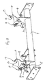
Fig. 3 Teile der Verbindung am Fuß in der entriegelten Stellung zeigt und -
Fig. 4 Teile der Verbindung ausFig. 3 in der verriegelten Stellung. - In den Figuren ist als Beispiel für ein Möbel mit einem Sitzteil und einem damit nach der Erfindung lösbar verbindbaren Unterbau ein sogenannter Sitz-Liege-Sessel 1 dargestellt, der ein Sitzteil 2 und einen Fuß 3 umfasst.
- Von dem Fuß 3 ist nur der obere Bereich angedeutet, in dem ein Querrohr 4 für Seitenteile vorgesehen ist. An dem Querrohr 4 des Fußes 3 ist ebenfalls pro Seite des Sessels 1 je eine Lasche 5 angeschweißt.
- An jeder Lasche 5 ist wiederum ein Hebel 6 angelenkt, der und zwischen einer das Sitzteil 2 mit dem Fuß 3 verriegelnden (vgl.
Fig. 4 ) und einer freigebenden (vgl.Fig. 3 ) Stellung um die Drehachse 7 verdrehbar ist. - Der Hebel 6 ist in Richtung der verriegelnden Stellung federbeaufschlagt bzw. mit einer Feder 8 gespannt (Siehe Pfeil in
Fig. 4 ). Die Lasche 5 und der Hebel 6 sind jeweils mit Befestigungsnasen 9, 10 für die Feder 8 versehen. - Die Befestigungsnasen 9, 10 und die Drehachse 7 sind so angeordnet, dass sie in eine
- Linie gebracht werden können, so dass der Hebel 6 in der entriegelten Stellung verbleibt, da die Federkraft sich "aufhebt", wenn die Befestigungsnasen 9,10 auf gegenüberliegenden Seiten der Drehachse angeordnet sind.
- Der Hebel 6 ist mit einem einen Hinterschnitt 12 ausbildenden Bügel 11 versehen ist, der in der verriegelnden Stellung einen Bolzen 13 des Sitzteils 2 umgreift.
- Die Lasche 5 weist eine offene Ausnehmung 14 auf, in der der Bolzen 13 in der verriegelten Stellung liegt und dort vom Bügel 11 des Hebels 6 umgriffen wird.
- Des Weiteren weist die Lasche 5 einen Hinterschnitt 15 auf, in den ein am Sitzteil 3 vorgesehener weiterer Bolzen 16 eingreift.
- Zusätzlich ist am Hebel 6 ein Vorsprung 17 vorgesehen, der derart angeordnet ist, dass er in der entriegelten Stellung des Hebels 6 im unteren Bereich der Ausnehmung 14 liegt.
- In der zusammengesteckten Stellung des Sitzteils 2 mit dem Fuß 3 legen der Hinterschnitt 15 und der Bolzen 16 zusammen mit dem Hebel 6, dem Bolzen 13 und der Ausnehmung 12 das Sitzteil 2 bezüglich des Fußes 3 fest.
- Der Hebel 6 nimmt dann die Verriegelung vor.
- Um das Zusammenstecken zu erleichtern, ist die Lasche 5 oberhalb der Ausnehmung 14 und des Hinterschnitts 15 mit abgewinkelten Einführhilfen 18, 19 versehene.
- Die Lasche 5 ist im Bereich der Öffnung der Ausnehmung 14 mit einer Abwinkelung 20 versehen, unter der der Hebel 6 in der verriegelten Stellung angeordnet.
- Zusätzlich ist die Lasche 5 mit einer weiteren Abwinklung 21 versehen, die eine Auflagefläche für ein Blech 22 des Sitzteils 2 bereitstellt.
- Beim Zusammenstecken wird wie folgt vorgegangen:
Zuerst wird der Hebel 6 in die entriegelte Stellung durch Verdrehen um die Achse 7 gebracht, so dass die Befestigungsnasen 9, 10 der Feder 8 auf diagonal gegenüberliegenden Seiten der Achse liegen. Somit bewirkt die Kraft der Feder 8 keine Drehung des Hebels 6. - Dann wird das Sitzteil 2 mit Hilfe der Einführhilfen 18, 19 an den jeweiligen Oberseiten der Laschen 5 mit den vorderen Bolzen 16 in die Hinterschnitte 15 eingeführt und zum Anschlag gebracht.
- Anschließend wird das Sitzteil 2 mit den hinteren Bolzen 13 in die Ausnehmungen 14 der Laschen 5 eingeführt und dabei der jeweilige Vorsprung 17 der entriegelten Hebel 6 nach unten gedrückt, wodurch der Hebel 6 nun aus der entriegelten Stellung durch die jetzt wirkende Kraft der Feder 8, da die Befestigungsnasen 9, 10 nun nicht mehr diagonal gegenüber liegen, sich um die Achse 7 mit dem Bügel 11 nach hinten verdreht, so dass der Bügel 11 den Bolzen 13 in der Ausnehmung 14 verriegelt (vgl.
Figur 4 ). -
- 1
- Sessel
- 2
- Sitzteil
- 3
- Fuß
- 4
- Querrohr
- 5
- Lasche
- 6
- Hebel
- 7
- Drehachse
- 8
- Feder
- 9
- Befestigungsnase
- 10
- Befestigungsnase
- 11
- Bügel
- 12
- Hinterschnitt
- 13
- Bolzen
- 14
- Ausnehmung
- 15
- Hinterschnitt
- 16
- Bolzen
- 17
- Vorsprung
- 18
- Einführhilfe
- 19
- Einführhilfe
- 20
- Abwinkelung
- 21
- Abwinklung
- 22
- Blech
Claims (12)
- Möbel (1) mit einem Sitzteil (2) und mit einem stützenden Unterbau (3), wobei eine Vorrichtung für die lösbare Verbindung des Sitzteils (2) mit dem Unterbau (3) vorgesehen ist, die Vorrichtung mindestens einen Hebel (6) aufweist, der zwischen einer das Sitzteil (2) mit dem Unterbau (3) verriegelnden und einer freigebenden Stellung beweglich ist und der Hebel (6) am Unterbau (3) oder Sitzteil (2) angeordnet ist und mit einem einen Hinterschnitt (12) ausbildenden Bügel (11) versehen ist, der in der verriegelnden Stellung einen Bolzen (13) am Sitzteil (2) oder am Unterbau umgreift.
- Möbel nach Anspruch 1, dadurch gekennzeichnet, dass der Hebel (6) in Richtung der verriegelnden Stellung federbeaufschlagt ist.
- Möbel nach Anspruch 1 oder 2, dadurch gekennzeichnet, dass die Vorrichtung mindestens eine Lasche (5) am Unterbau (3) oder Sitzteil aufweist, die mit einem Hinterschnitt (15) versehen ist, in den ein am Sitzteil (2) oder am Unterbau vorgesehener Bolzen (16) eingreift.
- Möbel nach Anspruch 3, dadurch gekennzeichnet, dass der Hebel (6) an der Lasche (5) angelenkt ist.
- Möbel nach Anspruch 3 oder 4, dadurch gekennzeichnet, dass die Lasche (5) und der Hebel (6) mit Befestigungsnasen (9, 10) für eine Feder (8) versehen sind.
- Möbel nach Anspruch 5, dadurch gekennzeichnet, dass die Befestigungsnasen (9, 10) und die Drehachse (7) so angeordnet sind, dass sie in eine Linie gebracht werden können, so dass der Hebel (6) in der entriegelten Stellung verbleibt.
- Möbel nach einem der Ansprüche 3 bis 6, dadurch gekennzeichnet, dass die Lasche (5) eine offene Ausnehmung (14) aufweist, in der der Bolzen (13) in der verriegelten Stellung liegt und dort vom Bügel (11) des Hebels (6) umgriffen wird.
- Möbel nach Anspruch 7, dadurch gekennzeichnet, dass am Hebel (6) ein Vorsprung (17) vorgesehen ist, der derart angeordnet ist, dass er in der entriegelten Stellung des Hebels (6) im unteren Bereich der Ausnehmung (14) liegt.
- Möbel nach Anspruch 8, dadurch gekennzeichnet, dass der Hinterschnitt (15) und der Bolzen (16) zusammen mit dem Hebel (6), dem Bolzen (13) und der Ausnehmung (14) ausgebildet und angeordnet sind, um das Sitzteil (2) bezüglich des Unterbaus (3) festzulegen.
- Möbel nach einem der Ansprüche 7 bis 9, dadurch gekennzeichnet, dass die Lasche (5) oberhalb der Ausnehmung (14) und des Hinterschnitts (15) mit abgewinkelten Einführhilfen (18, 19) versehen ist.
- Möbel nach einem der Ansprüche 7 bis 10, dadurch gekennzeichnet, dass die Lasche (5) im Bereich der Öffnung der Ausnehmung (14) mit einer Abwinkelung (20) versehen ist, unter der der Hebel (6) in der verriegelten Stellung angeordnet ist.
- Möbel nach einem der Ansprüche 3 bis 11, dadurch gekennzeichnet, dass die Lasche (5) mit einer weiteren Abwinklung (21) versehen ist, die eine Auflagefläche für das Sitzteil oder den Unterbau bereitstellt.
Priority Applications (1)
| Application Number | Priority Date | Filing Date | Title |
|---|---|---|---|
| PL08864699T PL2240049T3 (pl) | 2007-12-21 | 2008-12-02 | Mebel |
Applications Claiming Priority (2)
| Application Number | Priority Date | Filing Date | Title |
|---|---|---|---|
| DE202007018096U DE202007018096U1 (de) | 2007-12-21 | 2007-12-21 | Möbel |
| PCT/EP2008/066649 WO2009080451A1 (de) | 2007-12-21 | 2008-12-02 | Möbel |
Publications (2)
| Publication Number | Publication Date |
|---|---|
| EP2240049A1 EP2240049A1 (de) | 2010-10-20 |
| EP2240049B1 true EP2240049B1 (de) | 2012-08-01 |
Family
ID=39185564
Family Applications (1)
| Application Number | Title | Priority Date | Filing Date |
|---|---|---|---|
| EP08864699A Not-in-force EP2240049B1 (de) | 2007-12-21 | 2008-12-02 | Möbel |
Country Status (8)
| Country | Link |
|---|---|
| US (1) | US8544959B2 (de) |
| EP (1) | EP2240049B1 (de) |
| CN (1) | CN101925317B (de) |
| DE (1) | DE202007018096U1 (de) |
| DK (1) | DK2240049T3 (de) |
| ES (1) | ES2392124T3 (de) |
| PL (1) | PL2240049T3 (de) |
| WO (1) | WO2009080451A1 (de) |
Families Citing this family (3)
| Publication number | Priority date | Publication date | Assignee | Title |
|---|---|---|---|---|
| CN102204759B (zh) * | 2011-05-17 | 2014-03-19 | 长春富维—江森自控汽车饰件系统有限公司 | 座椅翻转机构 |
| US10463153B2 (en) * | 2016-06-09 | 2019-11-05 | Steelcase Inc. | Seating arrangement |
| US10874222B2 (en) | 2017-09-22 | 2020-12-29 | Ashley Furniture Industries, Inc. | Ready to assemble furniture |
Family Cites Families (42)
| Publication number | Priority date | Publication date | Assignee | Title |
|---|---|---|---|---|
| US3915493A (en) * | 1974-11-21 | 1975-10-28 | Gen Motors Corp | Seat cushion retainer device |
| US4365840A (en) * | 1980-10-30 | 1982-12-28 | Coach & Car Equipment Corporation | Seat with back cushion attachment |
| DE3217140C2 (de) * | 1982-05-07 | 1986-08-14 | P.A. Rentrop, Hubbert & Wagner Fahrzeugausstattungen Gmbh & Co Kg, 3060 Stadthagen | Sitz, insbesondere Kraftfahrzeugsitz mit im Abstand zueinander liegenden Beschlägen |
| DE8530363U1 (de) | 1985-10-26 | 1986-01-30 | benze collection Sitzmöbelwerk GmbH & Co KG, 3252 Bad Münder | Stuhl |
| JPS63137054A (ja) * | 1986-11-28 | 1988-06-09 | Ikeda Bussan Co Ltd | 車両用シ−ト |
| CA1282681C (en) * | 1987-03-13 | 1991-04-09 | Gulam Premji | Seat release mechanism |
| US4759580A (en) * | 1987-07-06 | 1988-07-26 | Hoover Universal, Inc. | Bench seat floor latching mechanism |
| IL99934A (en) * | 1990-11-30 | 1994-10-07 | La Z Boy Chair Co | Back to the chair that can be unloaded |
| FR2704492B1 (fr) * | 1993-04-27 | 1995-06-16 | Renault | Support de siege de vehicule automobile. |
| US5338096A (en) * | 1993-10-19 | 1994-08-16 | Taiwan Charwell Enterprise, Co., Ltd. | Locking device for a front seat of a double stroller |
| US5567008A (en) * | 1994-11-04 | 1996-10-22 | Cosco, Inc. | Portable infant seat having a detachable base |
| US5558260A (en) * | 1995-04-18 | 1996-09-24 | Reichert; Cory A. | Detachable motorcycle passenger seat and/or luggage rack |
| US5667232A (en) * | 1995-07-20 | 1997-09-16 | Harley-Davidson Motor Company | Detachable sissy bar |
| US5931529A (en) * | 1997-08-08 | 1999-08-03 | La-Z-Boy Incorporated | Apparatus for securing independent sections of a modular seating assembly |
| FR2772320B1 (fr) * | 1997-12-12 | 2000-02-11 | Faure Bertrand Equipements Sa | Siege a entraxe modulable |
| JPH11245695A (ja) * | 1998-03-03 | 1999-09-14 | Mazda Motor Corp | 車両のシート装置 |
| DE29811414U1 (de) | 1998-06-25 | 1998-11-05 | Wei Ri Healthy Chair Co | Gesundheitsstuhl |
| IT1308620B1 (it) * | 1999-02-19 | 2002-01-09 | Peg Perego Spa | Assieme separabile di telaio ed elemento di accoglimento di unbambino. |
| US6367880B1 (en) * | 1999-11-05 | 2002-04-09 | Alfred G. Niederman | Modular upholstered furniture construction |
| US6758450B2 (en) * | 1999-11-05 | 2004-07-06 | Alfred G. Niederman | Modular furniture including interchangeable upholstery |
| AUPQ597500A0 (en) * | 2000-03-02 | 2000-03-23 | Camatic Pty. Limited | Improved theatre chair |
| US6443344B1 (en) * | 2000-05-17 | 2002-09-03 | Harley-Davidson Motor Company Group, Inc. | Securing mechanism for detachable motorcycle component |
| JP2002274440A (ja) * | 2001-03-15 | 2002-09-25 | Fuji Heavy Ind Ltd | 車両の後部車体構造 |
| US6648393B1 (en) * | 2002-12-17 | 2003-11-18 | General Motors Corporation | Lateral sliding seat |
| JP4216147B2 (ja) * | 2003-02-13 | 2009-01-28 | 本田技研工業株式会社 | 車両用シート |
| US6983526B2 (en) * | 2003-06-24 | 2006-01-10 | M & C Corporation | Cold formed latch wire |
| US7111903B1 (en) * | 2003-08-14 | 2006-09-26 | Bill Snelson | Supplemental motorcycle seat |
| US20050082894A1 (en) | 2003-10-21 | 2005-04-21 | Ching-Hui Chi | Structure connection of motion chair |
| KR100551843B1 (ko) * | 2003-11-08 | 2006-02-13 | 기아자동차주식회사 | 차량용 탈착식 시트의 록킹장치 |
| JP2005162070A (ja) * | 2003-12-03 | 2005-06-23 | Yamaha Motor Co Ltd | 乗り物における構成部品の着脱装置 |
| JP4081053B2 (ja) * | 2004-08-06 | 2008-04-23 | 本田技研工業株式会社 | 車両用シート |
| KR20080017062A (ko) * | 2005-06-02 | 2008-02-25 | 인티어 오토모티브, 인크. | 기립 위치를 갖는 차량 시트 조립체 |
| KR20060126360A (ko) * | 2005-06-03 | 2006-12-07 | 아프리카 이쿠지켄큐카이 아프리카 카사이 가부시키가이샤 | 착탈식 차일드 시트 |
| NZ540611A (en) * | 2005-06-08 | 2006-06-30 | Roger Thomas Mascull | A seat |
| DE202005014571U1 (de) * | 2005-09-15 | 2005-11-17 | Kintec-Solution Gmbh | Sessel |
| US7306290B2 (en) * | 2005-11-30 | 2007-12-11 | L & G Property Management Company | Knockdown attachment mechanism for a reclining chair |
| CN2921405Y (zh) * | 2006-04-28 | 2007-07-11 | 东莞贯新幼童用品有限公司 | 快速卡合及拆卸机构 |
| CN2920013Y (zh) * | 2006-05-08 | 2007-07-11 | 基胜工业(上海)有限公司 | 座椅快速组装卡制结构 |
| DE202007009765U1 (de) | 2007-07-04 | 2007-10-18 | Lütkemeier, Albert | Klappsitz für eine Sitzbank |
| US8308229B2 (en) * | 2009-02-07 | 2012-11-13 | Mattel, Inc. | Strap management system for infant support structure |
| US9125496B2 (en) * | 2010-06-25 | 2015-09-08 | Sauder Manufactering Co. | Sleep system |
| US9022340B2 (en) * | 2011-03-21 | 2015-05-05 | Techform Products Limited | Formed tube with formed wire rivet |
-
2007
- 2007-12-21 DE DE202007018096U patent/DE202007018096U1/de not_active Expired - Lifetime
-
2008
- 2008-12-02 US US12/809,797 patent/US8544959B2/en not_active Expired - Fee Related
- 2008-12-02 ES ES08864699T patent/ES2392124T3/es active Active
- 2008-12-02 DK DK08864699.7T patent/DK2240049T3/da active
- 2008-12-02 PL PL08864699T patent/PL2240049T3/pl unknown
- 2008-12-02 EP EP08864699A patent/EP2240049B1/de not_active Not-in-force
- 2008-12-02 WO PCT/EP2008/066649 patent/WO2009080451A1/de active Application Filing
- 2008-12-02 CN CN2008801253170A patent/CN101925317B/zh not_active Expired - Fee Related
Also Published As
| Publication number | Publication date |
|---|---|
| US8544959B2 (en) | 2013-10-01 |
| US20100270847A1 (en) | 2010-10-28 |
| ES2392124T3 (es) | 2012-12-04 |
| DE202007018096U1 (de) | 2008-03-13 |
| DK2240049T3 (da) | 2012-10-29 |
| WO2009080451A1 (de) | 2009-07-02 |
| CN101925317A (zh) | 2010-12-22 |
| CN101925317B (zh) | 2012-11-28 |
| PL2240049T3 (pl) | 2013-03-29 |
| EP2240049A1 (de) | 2010-10-20 |
Similar Documents
| Publication | Publication Date | Title |
|---|---|---|
| DE3915947C2 (de) | Sitzmöbel | |
| DE102006023176B4 (de) | Anordnung für einen Sitz für ein Fahrzeug zur Verringerung seiner Gesamtlängsabmessung | |
| DE102005051236B4 (de) | Sessel | |
| WO2002074133A1 (de) | In ein bett umwandelbares siztmöbel | |
| EP2240049B1 (de) | Möbel | |
| DE8310049U1 (de) | Von der sitz- in die liegeposition ueberfuehrbares moebel | |
| DE202019102922U1 (de) | Ausklappbares Sofa | |
| AT412188B (de) | In ein bett umwandelbares sitzmöbel | |
| AT413518B (de) | Rahmen für sessel, insbesondere von sesselliften | |
| AT403428B (de) | Liege- und/oder sitzmöbel | |
| DE102009051119A1 (de) | Stuhl | |
| DE202019100109U1 (de) | Sitzmöbelchassis | |
| DE3232860C2 (de) | Kombinationsmöbel mit zwei Liegen auf einem Traggestell | |
| EP1186496B1 (de) | Sitzbank für einen Sessel einer Sesselbahn | |
| AT514820B1 (de) | Lehnenbeschlag | |
| DE1945705C (de) | Lehnstuhl | |
| DE2262594C3 (de) | Polstersitz o.dgl | |
| AT393074B (de) | Sitz- und liegemoebel | |
| EP2614752B1 (de) | Polstermöbel | |
| DE1779464C (de) | Sitz- und Schlafmöbel | |
| EP2528476B1 (de) | Sitzmöbel | |
| AT407948B (de) | Sitz- und liegemöbel | |
| DE202008004970U1 (de) | Stuhl, insbesondere mit verstellbarer Lehne und Vorrichtung zur Ablage und/oder zur Aufbewahrung eines Gegenstandes | |
| WO2009132829A1 (de) | Möbelstück | |
| DE202007005583U1 (de) | Hollywoodschaukel |
Legal Events
| Date | Code | Title | Description |
|---|---|---|---|
| PUAI | Public reference made under article 153(3) epc to a published international application that has entered the european phase |
Free format text: ORIGINAL CODE: 0009012 |
|
| 17P | Request for examination filed |
Effective date: 20100629 |
|
| AK | Designated contracting states |
Kind code of ref document: A1 Designated state(s): AT BE BG CH CY CZ DE DK EE ES FI FR GB GR HR HU IE IS IT LI LT LU LV MC MT NL NO PL PT RO SE SI SK TR |
|
| AX | Request for extension of the european patent |
Extension state: AL BA MK RS |
|
| DAX | Request for extension of the european patent (deleted) | ||
| GRAP | Despatch of communication of intention to grant a patent |
Free format text: ORIGINAL CODE: EPIDOSNIGR1 |
|
| RAP1 | Party data changed (applicant data changed or rights of an application transferred) |
Owner name: KINTEC-SOLUTION GMBH |
|
| GRAS | Grant fee paid |
Free format text: ORIGINAL CODE: EPIDOSNIGR3 |
|
| GRAA | (expected) grant |
Free format text: ORIGINAL CODE: 0009210 |
|
| AK | Designated contracting states |
Kind code of ref document: B1 Designated state(s): AT BE BG CH CY CZ DE DK EE ES FI FR GB GR HR HU IE IS IT LI LT LU LV MC MT NL NO PL PT RO SE SI SK TR |
|
| REG | Reference to a national code |
Ref country code: GB Ref legal event code: FG4D Free format text: NOT ENGLISH |
|
| REG | Reference to a national code |
Ref country code: AT Ref legal event code: REF Ref document number: 568190 Country of ref document: AT Kind code of ref document: T Effective date: 20120815 Ref country code: CH Ref legal event code: EP |
|
| REG | Reference to a national code |
Ref country code: IE Ref legal event code: FG4D Free format text: LANGUAGE OF EP DOCUMENT: GERMAN |
|
| REG | Reference to a national code |
Ref country code: DE Ref legal event code: R096 Ref document number: 502008007846 Country of ref document: DE Effective date: 20120927 |
|
| REG | Reference to a national code |
Ref country code: DK Ref legal event code: T3 |
|
| REG | Reference to a national code |
Ref country code: NL Ref legal event code: T3 |
|
| REG | Reference to a national code |
Ref country code: ES Ref legal event code: FG2A Ref document number: 2392124 Country of ref document: ES Kind code of ref document: T3 Effective date: 20121204 |
|
| REG | Reference to a national code |
Ref country code: LT Ref legal event code: MG4D Effective date: 20120801 |
|
| PG25 | Lapsed in a contracting state [announced via postgrant information from national office to epo] |
Ref country code: LT Free format text: LAPSE BECAUSE OF FAILURE TO SUBMIT A TRANSLATION OF THE DESCRIPTION OR TO PAY THE FEE WITHIN THE PRESCRIBED TIME-LIMIT Effective date: 20120801 Ref country code: CY Free format text: LAPSE BECAUSE OF FAILURE TO SUBMIT A TRANSLATION OF THE DESCRIPTION OR TO PAY THE FEE WITHIN THE PRESCRIBED TIME-LIMIT Effective date: 20120801 Ref country code: HR Free format text: LAPSE BECAUSE OF FAILURE TO SUBMIT A TRANSLATION OF THE DESCRIPTION OR TO PAY THE FEE WITHIN THE PRESCRIBED TIME-LIMIT Effective date: 20120801 Ref country code: NO Free format text: LAPSE BECAUSE OF FAILURE TO SUBMIT A TRANSLATION OF THE DESCRIPTION OR TO PAY THE FEE WITHIN THE PRESCRIBED TIME-LIMIT Effective date: 20121101 Ref country code: FI Free format text: LAPSE BECAUSE OF FAILURE TO SUBMIT A TRANSLATION OF THE DESCRIPTION OR TO PAY THE FEE WITHIN THE PRESCRIBED TIME-LIMIT Effective date: 20120801 Ref country code: IS Free format text: LAPSE BECAUSE OF FAILURE TO SUBMIT A TRANSLATION OF THE DESCRIPTION OR TO PAY THE FEE WITHIN THE PRESCRIBED TIME-LIMIT Effective date: 20121201 |
|
| PG25 | Lapsed in a contracting state [announced via postgrant information from national office to epo] |
Ref country code: SI Free format text: LAPSE BECAUSE OF FAILURE TO SUBMIT A TRANSLATION OF THE DESCRIPTION OR TO PAY THE FEE WITHIN THE PRESCRIBED TIME-LIMIT Effective date: 20120801 Ref country code: SE Free format text: LAPSE BECAUSE OF FAILURE TO SUBMIT A TRANSLATION OF THE DESCRIPTION OR TO PAY THE FEE WITHIN THE PRESCRIBED TIME-LIMIT Effective date: 20120801 Ref country code: LV Free format text: LAPSE BECAUSE OF FAILURE TO SUBMIT A TRANSLATION OF THE DESCRIPTION OR TO PAY THE FEE WITHIN THE PRESCRIBED TIME-LIMIT Effective date: 20120801 Ref country code: PT Free format text: LAPSE BECAUSE OF FAILURE TO SUBMIT A TRANSLATION OF THE DESCRIPTION OR TO PAY THE FEE WITHIN THE PRESCRIBED TIME-LIMIT Effective date: 20121203 Ref country code: GR Free format text: LAPSE BECAUSE OF FAILURE TO SUBMIT A TRANSLATION OF THE DESCRIPTION OR TO PAY THE FEE WITHIN THE PRESCRIBED TIME-LIMIT Effective date: 20121102 |
|
| REG | Reference to a national code |
Ref country code: PL Ref legal event code: T3 |
|
| PG25 | Lapsed in a contracting state [announced via postgrant information from national office to epo] |
Ref country code: RO Free format text: LAPSE BECAUSE OF FAILURE TO SUBMIT A TRANSLATION OF THE DESCRIPTION OR TO PAY THE FEE WITHIN THE PRESCRIBED TIME-LIMIT Effective date: 20120801 Ref country code: EE Free format text: LAPSE BECAUSE OF FAILURE TO SUBMIT A TRANSLATION OF THE DESCRIPTION OR TO PAY THE FEE WITHIN THE PRESCRIBED TIME-LIMIT Effective date: 20120801 Ref country code: CZ Free format text: LAPSE BECAUSE OF FAILURE TO SUBMIT A TRANSLATION OF THE DESCRIPTION OR TO PAY THE FEE WITHIN THE PRESCRIBED TIME-LIMIT Effective date: 20120801 |
|
| PG25 | Lapsed in a contracting state [announced via postgrant information from national office to epo] |
Ref country code: SK Free format text: LAPSE BECAUSE OF FAILURE TO SUBMIT A TRANSLATION OF THE DESCRIPTION OR TO PAY THE FEE WITHIN THE PRESCRIBED TIME-LIMIT Effective date: 20120801 |
|
| PLBE | No opposition filed within time limit |
Free format text: ORIGINAL CODE: 0009261 |
|
| STAA | Information on the status of an ep patent application or granted ep patent |
Free format text: STATUS: NO OPPOSITION FILED WITHIN TIME LIMIT |
|
| BERE | Be: lapsed |
Owner name: KINTEC-SOLUTION G.M.B.H. Effective date: 20121231 |
|
| 26N | No opposition filed |
Effective date: 20130503 |
|
| PG25 | Lapsed in a contracting state [announced via postgrant information from national office to epo] |
Ref country code: MC Free format text: LAPSE BECAUSE OF NON-PAYMENT OF DUE FEES Effective date: 20121231 Ref country code: BG Free format text: LAPSE BECAUSE OF FAILURE TO SUBMIT A TRANSLATION OF THE DESCRIPTION OR TO PAY THE FEE WITHIN THE PRESCRIBED TIME-LIMIT Effective date: 20121101 |
|
| REG | Reference to a national code |
Ref country code: CH Ref legal event code: PL |
|
| GBPC | Gb: european patent ceased through non-payment of renewal fee |
Effective date: 20121202 |
|
| REG | Reference to a national code |
Ref country code: DE Ref legal event code: R097 Ref document number: 502008007846 Country of ref document: DE Effective date: 20130503 |
|
| REG | Reference to a national code |
Ref country code: IE Ref legal event code: MM4A |
|
| PG25 | Lapsed in a contracting state [announced via postgrant information from national office to epo] |
Ref country code: BE Free format text: LAPSE BECAUSE OF NON-PAYMENT OF DUE FEES Effective date: 20121231 |
|
| PG25 | Lapsed in a contracting state [announced via postgrant information from national office to epo] |
Ref country code: LI Free format text: LAPSE BECAUSE OF NON-PAYMENT OF DUE FEES Effective date: 20121231 Ref country code: CH Free format text: LAPSE BECAUSE OF NON-PAYMENT OF DUE FEES Effective date: 20121231 Ref country code: IE Free format text: LAPSE BECAUSE OF NON-PAYMENT OF DUE FEES Effective date: 20121202 |
|
| PG25 | Lapsed in a contracting state [announced via postgrant information from national office to epo] |
Ref country code: GB Free format text: LAPSE BECAUSE OF NON-PAYMENT OF DUE FEES Effective date: 20121202 Ref country code: MT Free format text: LAPSE BECAUSE OF FAILURE TO SUBMIT A TRANSLATION OF THE DESCRIPTION OR TO PAY THE FEE WITHIN THE PRESCRIBED TIME-LIMIT Effective date: 20120801 |
|
| PG25 | Lapsed in a contracting state [announced via postgrant information from national office to epo] |
Ref country code: TR Free format text: LAPSE BECAUSE OF FAILURE TO SUBMIT A TRANSLATION OF THE DESCRIPTION OR TO PAY THE FEE WITHIN THE PRESCRIBED TIME-LIMIT Effective date: 20120801 |
|
| PG25 | Lapsed in a contracting state [announced via postgrant information from national office to epo] |
Ref country code: LU Free format text: LAPSE BECAUSE OF NON-PAYMENT OF DUE FEES Effective date: 20121202 |
|
| PG25 | Lapsed in a contracting state [announced via postgrant information from national office to epo] |
Ref country code: HU Free format text: LAPSE BECAUSE OF FAILURE TO SUBMIT A TRANSLATION OF THE DESCRIPTION OR TO PAY THE FEE WITHIN THE PRESCRIBED TIME-LIMIT Effective date: 20081202 |
|
| REG | Reference to a national code |
Ref country code: FR Ref legal event code: PLFP Year of fee payment: 8 |
|
| REG | Reference to a national code |
Ref country code: FR Ref legal event code: PLFP Year of fee payment: 9 |
|
| REG | Reference to a national code |
Ref country code: DE Ref legal event code: R082 Ref document number: 502008007846 Country of ref document: DE Representative=s name: KRAUS & WEISERT PATENTANWAELTE PARTGMBB, DE |
|
| REG | Reference to a national code |
Ref country code: FR Ref legal event code: PLFP Year of fee payment: 10 |
|
| REG | Reference to a national code |
Ref country code: FR Ref legal event code: PLFP Year of fee payment: 11 |
|
| PGFP | Annual fee paid to national office [announced via postgrant information from national office to epo] |
Ref country code: NL Payment date: 20191114 Year of fee payment: 12 Ref country code: DE Payment date: 20191119 Year of fee payment: 12 |
|
| PGFP | Annual fee paid to national office [announced via postgrant information from national office to epo] |
Ref country code: FR Payment date: 20191014 Year of fee payment: 12 Ref country code: DK Payment date: 20191210 Year of fee payment: 12 Ref country code: PL Payment date: 20191010 Year of fee payment: 12 Ref country code: IT Payment date: 20191209 Year of fee payment: 12 |
|
| PGFP | Annual fee paid to national office [announced via postgrant information from national office to epo] |
Ref country code: AT Payment date: 20191125 Year of fee payment: 12 |
|
| PGFP | Annual fee paid to national office [announced via postgrant information from national office to epo] |
Ref country code: ES Payment date: 20200102 Year of fee payment: 12 |
|
| REG | Reference to a national code |
Ref country code: DE Ref legal event code: R119 Ref document number: 502008007846 Country of ref document: DE |
|
| REG | Reference to a national code |
Ref country code: DK Ref legal event code: EBP Effective date: 20201231 |
|
| REG | Reference to a national code |
Ref country code: NL Ref legal event code: MM Effective date: 20210101 |
|
| REG | Reference to a national code |
Ref country code: AT Ref legal event code: MM01 Ref document number: 568190 Country of ref document: AT Kind code of ref document: T Effective date: 20201202 |
|
| PG25 | Lapsed in a contracting state [announced via postgrant information from national office to epo] |
Ref country code: NL Free format text: LAPSE BECAUSE OF NON-PAYMENT OF DUE FEES Effective date: 20210101 |
|
| PG25 | Lapsed in a contracting state [announced via postgrant information from national office to epo] |
Ref country code: AT Free format text: LAPSE BECAUSE OF NON-PAYMENT OF DUE FEES Effective date: 20201202 Ref country code: IT Free format text: LAPSE BECAUSE OF NON-PAYMENT OF DUE FEES Effective date: 20201202 Ref country code: FR Free format text: LAPSE BECAUSE OF NON-PAYMENT OF DUE FEES Effective date: 20201231 |
|
| PG25 | Lapsed in a contracting state [announced via postgrant information from national office to epo] |
Ref country code: DE Free format text: LAPSE BECAUSE OF NON-PAYMENT OF DUE FEES Effective date: 20210701 |
|
| PG25 | Lapsed in a contracting state [announced via postgrant information from national office to epo] |
Ref country code: DK Free format text: LAPSE BECAUSE OF NON-PAYMENT OF DUE FEES Effective date: 20201231 |
|
| REG | Reference to a national code |
Ref country code: ES Ref legal event code: FD2A Effective date: 20220207 |
|
| PG25 | Lapsed in a contracting state [announced via postgrant information from national office to epo] |
Ref country code: ES Free format text: LAPSE BECAUSE OF NON-PAYMENT OF DUE FEES Effective date: 20201203 |
|
| PG25 | Lapsed in a contracting state [announced via postgrant information from national office to epo] |
Ref country code: PL Free format text: LAPSE BECAUSE OF NON-PAYMENT OF DUE FEES Effective date: 20201202 |