EP2224585B1 - Motor control apparatus and image forming apparatus - Google Patents
Motor control apparatus and image forming apparatus Download PDFInfo
- Publication number
- EP2224585B1 EP2224585B1 EP10154887.3A EP10154887A EP2224585B1 EP 2224585 B1 EP2224585 B1 EP 2224585B1 EP 10154887 A EP10154887 A EP 10154887A EP 2224585 B1 EP2224585 B1 EP 2224585B1
- Authority
- EP
- European Patent Office
- Prior art keywords
- motor
- control
- value
- angular speed
- control value
- Prior art date
- Legal status (The legal status is an assumption and is not a legal conclusion. Google has not performed a legal analysis and makes no representation as to the accuracy of the status listed.)
- Active
Links
- 238000012546 transfer Methods 0.000 claims description 64
- 238000001514 detection method Methods 0.000 claims description 33
- 230000007274 generation of a signal involved in cell-cell signaling Effects 0.000 claims description 9
- 238000012937 correction Methods 0.000 claims description 6
- 230000004044 response Effects 0.000 claims description 6
- 238000010586 diagram Methods 0.000 description 13
- 238000000034 method Methods 0.000 description 12
- 230000008569 process Effects 0.000 description 10
- 238000004140 cleaning Methods 0.000 description 7
- 238000012545 processing Methods 0.000 description 5
- 230000032258 transport Effects 0.000 description 5
- 230000015572 biosynthetic process Effects 0.000 description 3
- 230000001133 acceleration Effects 0.000 description 2
- 238000006243 chemical reaction Methods 0.000 description 2
- 239000002699 waste material Substances 0.000 description 2
- 208000032544 Cicatrix Diseases 0.000 description 1
- 238000005299 abrasion Methods 0.000 description 1
- 238000013459 approach Methods 0.000 description 1
- 239000000969 carrier Substances 0.000 description 1
- 230000008878 coupling Effects 0.000 description 1
- 238000010168 coupling process Methods 0.000 description 1
- 238000005859 coupling reaction Methods 0.000 description 1
- 239000013078 crystal Substances 0.000 description 1
- 238000011161 development Methods 0.000 description 1
- 229910052736 halogen Inorganic materials 0.000 description 1
- 150000002367 halogens Chemical class 0.000 description 1
- 238000009413 insulation Methods 0.000 description 1
- 230000007246 mechanism Effects 0.000 description 1
- 238000012986 modification Methods 0.000 description 1
- 230000004048 modification Effects 0.000 description 1
- 230000009467 reduction Effects 0.000 description 1
- 231100000241 scar Toxicity 0.000 description 1
- 230000037387 scars Effects 0.000 description 1
- 238000007790 scraping Methods 0.000 description 1
Images


Classifications
-
- G—PHYSICS
- G03—PHOTOGRAPHY; CINEMATOGRAPHY; ANALOGOUS TECHNIQUES USING WAVES OTHER THAN OPTICAL WAVES; ELECTROGRAPHY; HOLOGRAPHY
- G03G—ELECTROGRAPHY; ELECTROPHOTOGRAPHY; MAGNETOGRAPHY
- G03G21/00—Arrangements not provided for by groups G03G13/00 - G03G19/00, e.g. cleaning, elimination of residual charge
- G03G21/16—Mechanical means for facilitating the maintenance of the apparatus, e.g. modular arrangements
- G03G21/1642—Mechanical means for facilitating the maintenance of the apparatus, e.g. modular arrangements for connecting the different parts of the apparatus
- G03G21/1647—Mechanical connection means
-
- B—PERFORMING OPERATIONS; TRANSPORTING
- B41—PRINTING; LINING MACHINES; TYPEWRITERS; STAMPS
- B41J—TYPEWRITERS; SELECTIVE PRINTING MECHANISMS, i.e. MECHANISMS PRINTING OTHERWISE THAN FROM A FORME; CORRECTION OF TYPOGRAPHICAL ERRORS
- B41J19/00—Character- or line-spacing mechanisms
- B41J19/18—Character-spacing or back-spacing mechanisms; Carriage return or release devices therefor
- B41J19/20—Positive-feed character-spacing mechanisms
- B41J19/202—Drive control means for carriage movement
-
- G—PHYSICS
- G03—PHOTOGRAPHY; CINEMATOGRAPHY; ANALOGOUS TECHNIQUES USING WAVES OTHER THAN OPTICAL WAVES; ELECTROGRAPHY; HOLOGRAPHY
- G03G—ELECTROGRAPHY; ELECTROPHOTOGRAPHY; MAGNETOGRAPHY
- G03G15/00—Apparatus for electrographic processes using a charge pattern
- G03G15/14—Apparatus for electrographic processes using a charge pattern for transferring a pattern to a second base
- G03G15/16—Apparatus for electrographic processes using a charge pattern for transferring a pattern to a second base of a toner pattern, e.g. a powder pattern, e.g. magnetic transfer
- G03G15/1605—Apparatus for electrographic processes using a charge pattern for transferring a pattern to a second base of a toner pattern, e.g. a powder pattern, e.g. magnetic transfer using at least one intermediate support
- G03G15/1615—Apparatus for electrographic processes using a charge pattern for transferring a pattern to a second base of a toner pattern, e.g. a powder pattern, e.g. magnetic transfer using at least one intermediate support relating to the driving mechanism for the intermediate support, e.g. gears, couplings, belt tensioning
-
- G—PHYSICS
- G03—PHOTOGRAPHY; CINEMATOGRAPHY; ANALOGOUS TECHNIQUES USING WAVES OTHER THAN OPTICAL WAVES; ELECTROGRAPHY; HOLOGRAPHY
- G03G—ELECTROGRAPHY; ELECTROPHOTOGRAPHY; MAGNETOGRAPHY
- G03G15/00—Apparatus for electrographic processes using a charge pattern
- G03G15/75—Details relating to xerographic drum, band or plate, e.g. replacing, testing
- G03G15/757—Drive mechanisms for photosensitive medium, e.g. gears
-
- H—ELECTRICITY
- H02—GENERATION; CONVERSION OR DISTRIBUTION OF ELECTRIC POWER
- H02P—CONTROL OR REGULATION OF ELECTRIC MOTORS, ELECTRIC GENERATORS OR DYNAMO-ELECTRIC CONVERTERS; CONTROLLING TRANSFORMERS, REACTORS OR CHOKE COILS
- H02P6/00—Arrangements for controlling synchronous motors or other dynamo-electric motors using electronic commutation dependent on the rotor position; Electronic commutators therefor
- H02P6/20—Arrangements for starting
- H02P6/21—Open loop start
-
- G—PHYSICS
- G03—PHOTOGRAPHY; CINEMATOGRAPHY; ANALOGOUS TECHNIQUES USING WAVES OTHER THAN OPTICAL WAVES; ELECTROGRAPHY; HOLOGRAPHY
- G03G—ELECTROGRAPHY; ELECTROPHOTOGRAPHY; MAGNETOGRAPHY
- G03G2221/00—Processes not provided for by group G03G2215/00, e.g. cleaning or residual charge elimination
- G03G2221/16—Mechanical means for facilitating the maintenance of the apparatus, e.g. modular arrangements and complete machine concepts
- G03G2221/1651—Mechanical means for facilitating the maintenance of the apparatus, e.g. modular arrangements and complete machine concepts for connecting the different parts
- G03G2221/1657—Mechanical means for facilitating the maintenance of the apparatus, e.g. modular arrangements and complete machine concepts for connecting the different parts transmitting mechanical drive power
Definitions
- the present invention relates to a motor control apparatus for controlling a DC motor and an image forming apparatus including the motor control apparatus.
- Fig. 11B even if the angular speed is controlled to start at a low control value when a DC is started and increase to a target control value, when the angular speed comes closer to the target angular speed, its increase turns to be non-linear as illustrated in Fig. 11A though the angular speed of the DC motor increases linearly up to halfway to the target angular speed. It is difficult to match the nonlinear characteristics among the different motors. Therefore, if the angular speeds of DC motors can be started and accelerated linearly up to the target value, startup characteristics of the motors can be brought in line.
- US2005195226 discloses a printer-control apparatus which sequentially records a relative position of a printing medium specified from an accumulated carried amount of the printing medium and/or driving speed of a paper-feed motor for driving a printing medium carrying mechanism for carrying the printing medium for a period longer than reaction delay time at every time interval shorter than the reaction delay time as a time difference between a time when a front edge or a rear edge of the printing medium reaches an initial position of a swing pin of a mechanical paper detection sensor which detects the front edge and/or the rear edge of the printing medium by swinging operation of the swing pin and a time when the front or rear edge of the printing medium is detected.
- US 2002057023 discloses a driving motor in which the rotational force of a driving motor is transferred to a photosensitive drum via a planetary-roller reduction device, so that the photosensitive drum is rotated.
- a speed detector set on the shaft of the photosensitive drum detects the rotational speed of the photosensitive drum.
- the rotational speed of the driving motor is adjusted so that the photosensitive drum is rotated at a constant speed.
- the present invention is directed to enabling the angular speed of a motor to increase to a target angular speed at a predetermined rate.
- the present invention in its first aspect provides a motor control apparatus as specified in claims 1, 2, and 5 to 7.
- the present invention in its second aspect provides an image forming apparatus as specified in claims 3, 4, and 8.
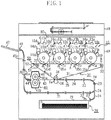
- Fig. 1 is a sectional view of an image forming apparatus according to an exemplary embodiment of the present invention.
- a color copying machine according to this exemplary embodiment has a plurality of image forming units arranged in parallel, and operates by an intermediate transfer method.
- the color copying machine includes an image reading section 1R and an image output section 1P.
- the image reading diction 1R optically reads a document image, converts it into an electric signal, and sends this signal to the image reading section 1R.
- the image output section 1P includes a plurality of image forming units 10a, 10b, 10c, and 10d arranged side by side, a sheet feeding unit 20, an intermediate transfer unit 30, a fixing unit 40, a cleaning unit 50, a photo sensor 60, and a control unit 80.
- the image forming units 10a, 10b, 10c, and 10d have the same structure.
- the photosensitive drums 11a, 11b, 11c, and 11d as first image carriers, which are rotatably supported by a rotary shaft, are driven in a direction indicated by an arrow.
- Primary charging units 12a, 12b, 12c, and 12d, exposure units 13a, 13b, 13c, and 13d, folding mirrors 16a, 16b, 16c, and 16d, developing apparatuses 14a, 14b, 14c, and 14d, and cleaning units 15a, 15b, 15d, and 15d are arranged in a rotating direction of the photosensitive drums 11a to 11d facing the outer circumferential faces of the drums.
- the primary charging units 12a to 12d give uniform electric charge to the outer circumferential faces of the photosensitive drums 11a to 11d.
- the exposure units 13a to 13d apply a laser beam to the photosensitive drums 11a to 11d via the folding mirrors 16a to 16d. In this manner, electrostatic latent images are formed on the photosensitive drums 11a to 11d.
- the electrostatic latent images on the photosensitive drums 11a to 11d are visualized by the developing apparatuses 14a to 14d which carry four color developers (hereafter called toner), namely, yellow, cyan, magenta, and black.
- the visible images (toner images) are transferred to an intermediate transfer belt 31 serving as a second image carrier in the intermediate transfer unit 30 at image transfer positions Ta, Tb, Tc, and Td.
- the cleaning units 15a, 15b, 15c, and 15d provided downstream of the image transfer positions Ta, Tb, Tc, and Td clean the surfaces of the photosensitive drums by scraping off the remaining toner on the drums which is not transferred to the intermediate transfer belt 31.
- the images are formed by successively repeating development using color toners.
- a sheet feeding unit 21 includes a cassette 21 to store sheet P, a pickup roller to send out sheets P one by one from the cassette 21, and a sheet feeding roller pair 23 to further transport the sheets P sent from the pickup roller 22.
- the sheet feeding unit 20 further includes a sheet feeding guide 24 and a registration roller pair 25 to send out the sheets P to a secondary transfer position Te in time with images on the intermediate transfer belt 31.
- the intermediate transfer unit 30 will now be described in detail.
- the intermediate transfer belt 31 is held by a drive roller 32 which transmits a driving force to the intermediate transfer belt 31, by a driven roller 33 driven by rotation of the intermediate transfer belt 31, and by a secondary transfer counter roller 34.
- a primary transfer plane A is formed between the drive roller 32 and the driven roller 33.
- the driven roller 32 is rotated by a motor (not illustrated).
- primary transfer chargers 35a to 35d are arranged at the back of the intermediate transfer belt 31.
- the secondary transfer counter roller 34 and the secondary transfer roller 36 are disposed to face each other.
- a secondary transfer position Te is formed by a nip between the secondary transfer roller 36 and the intermediate transfer belt 31.
- the secondary transfer roller 36 is pressurized to the intermediate transfer belt 31 with an appropriate pressure.
- a cleaning unit 50 configured to clean the image forming side of the intermediate transfer belt 31 is provided on the downstream side of the secondary transfer position Te of the intermediate transfer belt 31.
- the cleaning unit 50 includes a cleaning blade 51 configured to remove the toner on the intermediate transfer belt 31 and a waste toner box 52 to collect the waste toner scraped off by the cleaning blade 51.
- a fixing unit 40 includes a fixing roller 41a containing a heat source, such as a halogen heater and a fixing roller 41b pressed to the fixing roller 41a.
- the fixing unit 40 further includes a guide 43 configured to guide a sheet P into a nip area between the fixing rollers 41a, 41b, and a fixing-unit heat insulation cover 46 configured to contain the heat of the fixing unit 40.
- the fixing unit includes discharge rollers 44, two pairs of vertical pass rollers 45a, 45b, and discharge rollers 48 used to lead a sheet P discharged from the fixing rollers 41a, 41b to the outside of the apparatus, and also to a discharge tray 47 in which the sheets P are stacked.
- a recording sheet starts to be fed from the cassette 21.
- the pickup roller starts to feed sheets P one by one from the cassette 21.
- the sheet feeding roller pair 23 transports a sheet P to the registration roller pair 25 guided through the sheet feeding guide 24 by the sheet feeding roller pairs 23.
- the registration roller pair 25 is stationary, and a leading edge of the sheet P runs into the nip of the registration roller pair 25.
- the registration roller pair 25 starts to rotate in time with an image formed on the intermediate transfer belt 31.
- This rotation start timing is set in such a manner that the paper P coincides with the toner image on the intermediate transfer belt 31 at the secondary transfer position Te.
- a toner image formed on the photosensitive drum 11d is transferred primarily at the primary transfer position Td to the intermediate transfer belt 31 by the primary transfer charger 35d.
- This primarily transferred toner image is transported to the next primary transfer position Tc.
- image transfer takes place with a delay in time corresponding to a time of toner image transport between the image forming units.
- a next toner image is transferred onto the previous image where the two images match with each other.
- the sheet P is transported by the discharge rollers 44 and the vertical path rollers 45a. After the trailing edge of the sheet P passes the position 70 and advances for a predetermined distance, transport of the sheet P is started in the opposite direction. A flapper (not illustrated) is provided at the position 70 to prevent the sheet P from being sent to the fixing unit 40.
- the sheet P on one side of which an image formation processing has been performed, passes through a two-sided tray 71 and is again transported by the sheet feeding guide 24, and an image is formed on the other side of the sheet similar to the one side, and is fixed by the fixing rollers 41a, 41b. After this, the sheet P is transported by the discharge rollers 44, the two pairs of vertical pass rollers 45a, 45b, and the discharge rollers 48 to be discharged out of the apparatus, and to be stacked in the discharge tray 47.
- the photosensitive drums 11a to 11d each include a motor 100, such as a DC brushless motor.
- the motor is controlled by a control unit 200.
- a photosensitive drum 11 is rotated by a drive force transmitted via a gear 101, a drive shaft 103, and a coupling 102.
- An encoder wheel 111 is fixed to a drive shaft 103, and the drive shaft 103 and the encoder wheel 111 rotate at the same angular speed.
- An encoder 110 includes the encoder wheel 111 and an encoder sensor 112.
- the encoder wheel is a transparent circular disk, on which radial black lines are printed at regular intervals around its periphery.
- the encoder sensor has a light emitting portion and a light receiving portion placed in a manner of holding the disk at diametrically opposite positions. When a black part of the disk comes to the position of the light receiving portion, light to the light receiving portion is blocked, and a transparent part comes to the light receiving portion, the light is incident on the light receiving portion.
- the encoder sensor 112 generates a signal depending on whether light enters the light receiving portion. Therefore, the encoder 110 supplies the control unit 200 with a signal of a period corresponding to an angular speed of the drive shaft 103.
- the control unit 200 controls the motor 100 according to a signal from the encoder 110.
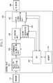
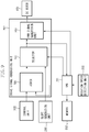
- Fig. 3 is a block diagram of the control unit 200.
- a rotation speed detection unit 203 detects a pulse width of a pulse signal from the encoder 110.
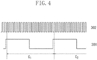
- the rotation speed detection unit 203 detects a pulse width of a pulse signal 301 by counting a number of clocks 302 in one period (C1: from a leading edge to the next leading edge of a pulse signal 301) of a pulse signal 301 illustrated in Fig. 4 .
- a clock 302 is a pulse signal with a period shorter than a period of a pulse signal 301.
- the clock 302 is generated by a crystal oscillator and input to the rotation speed detection unit 203.
- the rotation speed detection unit 203 calculates an angular speed from a detected pulse width.
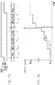
- Fig. 5A illustrates changes in the angular speed of the drive shaft 103 when the motor 100 is started and accelerated.
- Fig. 5B illustrates changes in clock counts (a period of a pulse signal) detected by the rotation speed detection unit 203.
- K is an arbitrary coefficient.
- Angular speed K / count number
- a difference calculation unit 204 calculates a difference between a detected angular speed from the rotation speed detection unit 203 and a target angular speed supplied from a CPU 201.
- the FB control unit 205 calculates a correction control value required to rotate the drive shaft 103 at a target angular speed based on a difference value output from the difference calculation unit 204 and feedback gain values K P , T I , and TD supplied from the CPU 201.
- a drive signal generation unit 207 generates a PWM control signal of a duty ratio based on a control value obtained by adding a correction control value from an FB control unit 205 and a target control value N TAG from the CPU 201, or a control value output from a slope generation unit 206.
- the PWM control signal is a signal for pulse width modulation control (PWM control) of the motor 100.
- the slope generation unit 206 outputs a control value which increases at a constant rate as time passes. Alternatively, the control value may be increased at a predetermined rate but not at a constant rate.
- a control value is used which is obtained by adding a correction control value output from the FB control unit 205 and a target control value N TAG output from the CPU 201.
- a control value output from the slope generation unit 206 is used. That is, the control value supplied to the drive signal generation unit 207 is the control value that controls a driving of the motor 100.
- Fig. 6 is a diagram illustrating processing in the FB control unit 205.
- the FB control unit 205 performs PID control based on a difference value e output from the difference calculation unit 204. Control values are calculated by equation 2. K P e + 1 T I ⁇ edt + T D de dt where K P , T I , and T D are feedback gain values of a proportional term 401, an integral term 402, and a derivative term 403 in PID control, and those gain values are determined by the CPU 201 according to angular speeds of the drive shaft 103.
- Figs. 7A and 7B are diagrams for illustrating processing in the slope generation unit 206.
- the slope generation unit 206 generates a control value that increases linearly at a constant rate as time elapses. Alternatively, the control value may be increased at a predetermined rate but not at a constant rate.
- the slope generation unit 206 in acceleration control, responding to a count start signal from the CPU 201, the slope generation unit 206 starts to increment a predetermined amount ⁇ K at intervals of predetermined time ⁇ T from an initial value N STA (first control value) until a maximum value N END (second control value), and outputs thus obtained control values.
- the CPU 201 Before inputting a count start signal to the slope generation unit 206, the CPU 201 sets the initial value N STA and the maximum value N END in the slope generation unit 206. On completing increment up to the maximum value N END , the slope generation unit 206 outputs a count end signal to inform the CPU 201 that counting has been completed, and terminates incrementing.
- the drive signal generation unit 207 supplies the motor 100 with a PWM control signal having an ON duty ratio that increases linearly at a constant rate.
- the angular speed of the motor 100 increases linearly following a control value that increases linearly indicated at t1 to t2 in Fig. 8B .
- the angular speed of the motor 100 during acceleration responds with a delay to a PWM control signal with a linearly increasing ON duty ratio, and does not coincide with the angular speed indicated by the PWM control signal.
- the CPU 201 sets the maximum value N END (by further incrementing a predetermined amount ⁇ K and a predetermined time ⁇ T if necessary) to a value that makes the angular speed increase linearly as indicated in Fig. 8A until the angular speed of the motor 100 reaches at least the target angular speed. More specifically, the maximum value N END is set to a value obtained by adding some percent to the target control value N TAG so that the angular speed of the motor reaches the target angular speed earlier than an increased control value reaches the maximum control value N END .
- the CPU 201 sets a control value corresponding to an angular speed, which is the target angular speed increased by a 10 percent. More specifically, the control value input to the motor 100 is increased linearly at a constant rate from a first control value corresponding to an angular speed lower than the target angular speed to a second control value corresponding to an angular speed higher than the target angular value. That is, the control value is increased such that the angular speed of the motor 100 linearly increases to the target angular speed while the motor 100 is accelerated.
- feed forward control is performed in which a control value input to the motor is increased linearly from a first control value corresponding to an angular speed lower than the target angular speed to a second control value corresponding to an angular speed higher than the target control value.
- the CPU 201 accelerates the motor 100 based on a control value output from the slope generation unit 206 as indicated by t1 to t2 in Fig. 8B until the motor 100 reaches the target angular speed (till t2 in Fig. 8B ).
- the CPU 210 controls the motor 100 based on a control value representing the target angular speed as indicated by the solid line from t2 on in Fig. 8B .
- the control value to be input to the motor 100 is switched to a level to maintain the motor 100 at the target angular speed based on a detection result of the rotation speed detection unit 203.
- the control unit 201 switches to feedback control to maintain the motor 100 at the target angular speed based on a detection result of the rotation speed detection unit 203.
- the predetermined time ⁇ T and the predetermined amount ⁇ K are determined by the performance of the motor 100 and the torque and the inertia of the load. For example, if a motor of a rated output of 15W is connected to a load of 30m ⁇ Nm and an inertia of 400g ⁇ cm2 (including a motor), it is preferable that ⁇ T and ⁇ K are set at values which enable the rotation number of the motor 100 to be increased from 0rpm to 2000rpm in about 300ms.
- the initial value N STA is preferably at a value that allows the motor 100 to start to rotate, and in this exemplary embodiment, the PWM signal has the ON duty ratio of about 10% to 20%.
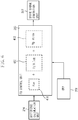
- Fig. 9 is a block diagram of the drive signal generation unit 207.
- a control signal from the FB control unit 205 and a control value representing a target angular speed from the CPU 201 are added by an adder 501.
- a control value as a result of addition in the adder 501 and a control value generated in the slope generation unit 206 are input to a selector 502. Based on a signal from the CPU 201, the selector 502 selects either one of the control value from the slope generation unit 206 and the control value from the adder 501.
- the CPU 201 causes the selector 502 to select the control value from the slope generation unit 206 until the target angular speed is reached, and causes the selector 502 to select the control value from the adder 501 after the target angular speed has been reached.
- the PWM signal generation unit 503 generates a PWM control signal based on the control signal from the selector 502 and information about PWM frequency from the CPU 201, and supplies the PWM control signal to the motor 100.
- the CPU 201 calculates an average value of control signals (PWM duty ratio) while the selector 502 is selecting a control signal from the adder 501 (during feedback control by the FB control unit 205), and stores this average control value in the memory 202.
- the CPU 201 inputs the average control value from the memory 202.
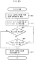
- Fig. 10 is a flowchart illustrating steps to be performed when the motor 100 is started and accelerated.
- the CPU instructs the selector 502 of the drive signal generation unit 207 to select a control value from the slope generation unit 206 (step S601).
- the CPU 201 by issuing a count start signal, causes the slope generation unit 206 to start to increment the control value from initial value N STA to the maximum value N END (step S602) .
- a control value incremented by the slope generation unit 206 is input to the selector 502.
- step S603 While the slope generation unit 206 is incrementing the control value, the CPU 201 monitors if a count end signal is output from the slope generation unit 206 to determine whether the control value, which is being incremented, has reached the maximum value N END (step S603). In step S603, if the maximum value N END has not been reached, the CPU 201 determines from a detection result of the rotation speed detection unit 203 whether the motor 100 has reached the target angular speed (step S604).
- step S604 the process returns to step S603, and if the motor has reached the target angular speed, the CPU 201 instructs the selector 502 of the drive signal generation unit 207 to select a control value from the adder 501 (step S605) .
- a control value selected by the selector 502 from the adder 50 is a value which maintains the motor 100 at the target angular speed.
- a control value selected by the selector 502 from the adder 50 is a value that corresponds to the target angular speed. If the motor 100 reaches the maximum value N END in step S603 before reaching the target angular speed at a predetermined time, the process advances to step S605.
- the CPU 201 While the selector 502 is in the process of selecting a control value from the slope generation unit 206, the CPU 201 continuously resets the FB control unit 205 to prevent the FB control unit 205 from being reset in response to the selector 502 switching to a control value from the FB control unit 205 (the adder 501).
- the angular speed of the motor 100 can be started and accelerated at the angular speed in a trapezoidal form illustrated in Fig. 8A .
- this type of control to the motor 100 that drives the photosensitive drums 11 and a motor that drives the drive roller 32 to rotate the intermediate transfer belt 31, their angular speeds can be increased in a trapezoidal form.
- the motor of the photosensitive drums 11 or the motor of the intermediate transfer belt 31 is a stepping motor
- the DC motor can be started and accelerated by control described above and the stepping motor can be started and accelerated by a well-known control method in a trapezoidal form, respectively.
- the difference in circumferential speed between the photosensitive drums 11 and the intermediate transfer belt can be eliminated, and slippage that occurs between the photosensitive drums and the intermediate transfer belt in the primary transfer section can be prevented and abrasion or scars on their surfaces can be prevented.
- an image forming apparatus is configured as follows.
- An image forming apparatus includes a first DC motor configured to drive photosensitive drums 11, a second DC motor configured to drive a roller that rotates an intermediate transfer belt 31, a first detection unit configured to detect an angular speed of the photosensitive drums 11, a second detection unit configured to detect an angular speed of the roller.
- the first control when the first DC motor is started and accelerated, increases a control value that controls a driving of the first DC motor at a first predetermined rate from a first control value corresponding to an angular speed lower than a first target angular speed up to a second control value corresponding to an angular speed higher than the first target angular speed, and switches the control value that controls the driving of the first DC motor to a control value corresponding to the first target angular speed in response to the detection result of the first detection unit reaching the first target angular speed.
- the second control unit when the second motor is started and accelerated, increases a control value that controls a driving of the second DC motor at a second predetermined rate from a third control value corresponding to an angular speed lower than a second target angular speed up to a fourth control value corresponding to an angular speed higher than the second target angular speed, and switches the control value that controls the driving of the second DC motor to a control value corresponding to the second target angular speed in response to the detection result of the second detection unit reaching the second target angular speed.
- the angular speed of the motor 100 is detected by the encoder 110 mounted on the drive shaft 103.
- an angular speed may be detected according to a frequency generator (FG) signal from the motor 100.
- FG frequency generator
- the above-described processing may be performed according to a result of detection of the circumferential speed or circulation speed of the photosensitive drum or the intermediate transfer belt 31.
- the angular speed of the motor 100 is controlled by PWM based on control values, but the angular speed of the motor 100 may be controlled by varying supply voltage based on control values.
Landscapes
- Physics & Mathematics (AREA)
- General Physics & Mathematics (AREA)
- Engineering & Computer Science (AREA)
- Power Engineering (AREA)
- Control Or Security For Electrophotography (AREA)
- Electrophotography Configuration And Component (AREA)
- Control Of Electric Motors In General (AREA)
- Control Of Direct Current Motors (AREA)
Applications Claiming Priority (1)
| Application Number | Priority Date | Filing Date | Title |
|---|---|---|---|
| JP2009046210 | 2009-02-27 |
Publications (3)
| Publication Number | Publication Date |
|---|---|
| EP2224585A2 EP2224585A2 (en) | 2010-09-01 |
| EP2224585A3 EP2224585A3 (en) | 2015-09-02 |
| EP2224585B1 true EP2224585B1 (en) | 2019-08-14 |
Family
ID=42227124
Family Applications (1)
| Application Number | Title | Priority Date | Filing Date |
|---|---|---|---|
| EP10154887.3A Active EP2224585B1 (en) | 2009-02-27 | 2010-02-26 | Motor control apparatus and image forming apparatus |
Country Status (5)
| Country | Link |
|---|---|
| US (1) | US8310178B2 (enExample) |
| EP (1) | EP2224585B1 (enExample) |
| JP (1) | JP2010226944A (enExample) |
| KR (1) | KR101238140B1 (enExample) |
| CN (1) | CN101820241B (enExample) |
Families Citing this family (40)
| Publication number | Priority date | Publication date | Assignee | Title |
|---|---|---|---|---|
| JP5404212B2 (ja) * | 2009-06-30 | 2014-01-29 | キヤノン株式会社 | モータ制御装置及び画像形成装置 |
| JP2011158320A (ja) * | 2010-01-29 | 2011-08-18 | Brother Industries Ltd | 検出システム、制御システム、画像形成システム及び制御方法 |
| JP5273117B2 (ja) * | 2010-09-30 | 2013-08-28 | ブラザー工業株式会社 | モータ制御装置 |
| KR101191355B1 (ko) * | 2010-12-15 | 2012-10-15 | 콘티넨탈 오토모티브 일렉트로닉스 유한회사 | 차량에 구비된 디씨모터의 소음 감쇠장치 |
| CN104271687B (zh) | 2012-03-05 | 2016-11-02 | 兰达公司 | 油墨膜构造 |
| US12053978B2 (en) | 2012-03-05 | 2024-08-06 | Landa Corporation Ltd. | Digital printing system |
| WO2013132418A2 (en) | 2012-03-05 | 2013-09-12 | Landa Corporation Limited | Digital printing process |
| US9498946B2 (en) | 2012-03-05 | 2016-11-22 | Landa Corporation Ltd. | Apparatus and method for control or monitoring of a printing system |
| US9643403B2 (en) | 2012-03-05 | 2017-05-09 | Landa Corporation Ltd. | Printing system |
| US11809100B2 (en) | 2012-03-05 | 2023-11-07 | Landa Corporation Ltd. | Intermediate transfer members for use with indirect printing systems and protonatable intermediate transfer members for use with indirect printing systems |
| CN109177531B (zh) | 2012-03-15 | 2020-11-27 | 兰达公司 | 打印系统的环形柔性皮带 |
| JP2013219871A (ja) * | 2012-04-05 | 2013-10-24 | Canon Inc | モータ制御装置 |
| CN202759406U (zh) * | 2012-06-28 | 2013-02-27 | 控制技术有限公司 | 变频器驱动多电机控制系统的优化切换系统 |
| GB201401173D0 (en) | 2013-09-11 | 2014-03-12 | Landa Corp Ltd | Ink formulations and film constructions thereof |
| GB2536489B (en) | 2015-03-20 | 2018-08-29 | Landa Corporation Ltd | Indirect printing system |
| US11806997B2 (en) | 2015-04-14 | 2023-11-07 | Landa Corporation Ltd. | Indirect printing system and related apparatus |
| JP6519405B2 (ja) * | 2015-08-24 | 2019-05-29 | シャープ株式会社 | モータ制御装置 |
| JP2017049637A (ja) * | 2015-08-31 | 2017-03-09 | シャープ株式会社 | 制御装置 |
| JP6665610B2 (ja) * | 2016-01-08 | 2020-03-13 | 株式会社ジェイテクト | モータ制御装置 |
| GB201609463D0 (en) | 2016-05-30 | 2016-07-13 | Landa Labs 2012 Ltd | Method of manufacturing a multi-layer article |
| CN112428691B (zh) | 2016-05-30 | 2022-09-27 | 兰达公司 | 数字印刷方法和系统 |
| CN114148098B (zh) | 2016-05-30 | 2025-03-07 | 兰达公司 | 数字印刷方法 |
| CN107248832B (zh) * | 2017-03-21 | 2023-09-05 | 基合半导体(宁波)有限公司 | 一种音圈马达驱动方法和系统 |
| CN106950958A (zh) * | 2017-03-28 | 2017-07-14 | 歌尔科技有限公司 | 直线控制方法、装置及双轮机器人 |
| JP7225230B2 (ja) | 2017-11-19 | 2023-02-20 | ランダ コーポレイション リミテッド | デジタル印刷システム |
| WO2019102297A1 (en) | 2017-11-27 | 2019-05-31 | Landa Corporation Ltd. | Digital printing system |
| US11707943B2 (en) | 2017-12-06 | 2023-07-25 | Landa Corporation Ltd. | Method and apparatus for digital printing |
| US11679615B2 (en) | 2017-12-07 | 2023-06-20 | Landa Corporation Ltd. | Digital printing process and method |
| JP2019180133A (ja) * | 2018-03-30 | 2019-10-17 | 日本電産サーボ株式会社 | モータユニット |
| WO2020003088A1 (en) | 2018-06-26 | 2020-01-02 | Landa Corporation Ltd. | An intermediate transfer member for a digital printing system |
| US10994528B1 (en) | 2018-08-02 | 2021-05-04 | Landa Corporation Ltd. | Digital printing system with flexible intermediate transfer member |
| US12001902B2 (en) | 2018-08-13 | 2024-06-04 | Landa Corporation Ltd. | Correcting distortions in digital printing by implanting dummy pixels in a digital image |
| JP7246496B2 (ja) | 2018-10-08 | 2023-03-27 | ランダ コーポレイション リミテッド | 印刷システムおよび方法に関する摩擦低減手段 |
| WO2020136517A1 (en) * | 2018-12-24 | 2020-07-02 | Landa Corporation Ltd. | A digital printing system |
| EP3946953A4 (en) | 2019-03-31 | 2022-12-14 | Landa Corporation Ltd. | SYSTEMS AND METHODS FOR PREVENTING OR MINIMIZING PRINT DEFECTS IN PRINTING PROCESSES |
| CN112448620A (zh) * | 2019-09-02 | 2021-03-05 | 深圳拓邦股份有限公司 | 电机刹车控制方法、装置及电动工具 |
| CN114746813A (zh) | 2019-11-25 | 2022-07-12 | 兰达公司 | 在数字印刷中使用红外辐射来干燥油墨 |
| US11321028B2 (en) | 2019-12-11 | 2022-05-03 | Landa Corporation Ltd. | Correcting registration errors in digital printing |
| EP4081866A4 (en) | 2019-12-29 | 2024-01-03 | Landa Corporation Ltd. | PRINTING METHOD AND SYSTEM |
| EP4264377A4 (en) | 2021-02-02 | 2024-11-13 | Landa Corporation Ltd. | MITIGATION OF DISTORTIONS IN PRINTED IMAGES |
Family Cites Families (16)
| Publication number | Priority date | Publication date | Assignee | Title |
|---|---|---|---|---|
| JPS5822592A (ja) * | 1981-08-03 | 1983-02-09 | Hitachi Ltd | モ−タの速度制御方法およびその速度制御装置 |
| US5148089A (en) * | 1989-08-31 | 1992-09-15 | Canon Kabushiki Kaisha | Method and apparatus for controlling motors |
| JPH0739181A (ja) | 1993-07-26 | 1995-02-07 | Toshiba Corp | Dcモータ制御回路 |
| JPH07129034A (ja) * | 1993-09-10 | 1995-05-19 | Konica Corp | 感光体駆動装置およびその制御方法 |
| US6420807B1 (en) * | 1999-03-10 | 2002-07-16 | Minolta Co., Ltd. | Rotator driving device, image forming apparatus using the rotator driving device, and method of driving rotator |
| ATE410309T1 (de) * | 1999-12-24 | 2008-10-15 | Seiko Epson Corp | Vorrichtung und verfahren zur motorsteuerung |
| DE60128164T2 (de) * | 2000-03-03 | 2008-03-06 | Seiko Epson Corp. | Motorsteuerungsvorrichtung und -verfahren |
| US6456808B1 (en) * | 2001-03-07 | 2002-09-24 | Hewlett-Packard Company | Systems and methods for reducing banding artifact in electrophotographic devices using drum velocity control |
| US7417400B2 (en) * | 2001-07-06 | 2008-08-26 | Seiko Epson Corporation | Motor controller |
| JP4026330B2 (ja) * | 2001-07-06 | 2007-12-26 | セイコーエプソン株式会社 | モータ制御方法、モータ制御装置、プリンタ、コンピュータプログラム、及び、コンピュータシステム |
| JP2003209990A (ja) | 2002-01-11 | 2003-07-25 | Hitachi Ltd | モートルの速度制御装置 |
| CN100399451C (zh) * | 2002-08-23 | 2008-07-02 | 联发科技股份有限公司 | 用于光驱的马达转速控制方法和马达转速控制装置 |
| JP2004334940A (ja) * | 2003-05-01 | 2004-11-25 | Pioneer Electronic Corp | 回転制御装置、その方法、そのプログラム、そのプログラムを記録した記録媒体、および、情報処理装置 |
| JP2005231243A (ja) * | 2004-02-20 | 2005-09-02 | Seiko Epson Corp | プリンタ制御装置及びプリンタ制御方法並びにプリンタ |
| JP4078559B2 (ja) | 2004-03-30 | 2008-04-23 | ブラザー工業株式会社 | モータ制御装置及び画像形成装置 |
| JP4671850B2 (ja) | 2005-12-07 | 2011-04-20 | 京セラミタ株式会社 | 画像形成装置 |
-
2010
- 2010-02-17 US US12/707,362 patent/US8310178B2/en active Active
- 2010-02-18 JP JP2010033853A patent/JP2010226944A/ja active Pending
- 2010-02-26 EP EP10154887.3A patent/EP2224585B1/en active Active
- 2010-02-26 CN CN2010101221643A patent/CN101820241B/zh not_active Expired - Fee Related
- 2010-02-26 KR KR1020100017524A patent/KR101238140B1/ko not_active Expired - Fee Related
Non-Patent Citations (1)
| Title |
|---|
| None * |
Also Published As
| Publication number | Publication date |
|---|---|
| JP2010226944A (ja) | 2010-10-07 |
| EP2224585A2 (en) | 2010-09-01 |
| KR101238140B1 (ko) | 2013-02-28 |
| CN101820241A (zh) | 2010-09-01 |
| CN101820241B (zh) | 2013-09-11 |
| EP2224585A3 (en) | 2015-09-02 |
| US20100220982A1 (en) | 2010-09-02 |
| KR20100098322A (ko) | 2010-09-06 |
| US8310178B2 (en) | 2012-11-13 |
Similar Documents
| Publication | Publication Date | Title |
|---|---|---|
| EP2224585B1 (en) | Motor control apparatus and image forming apparatus | |
| JP5145963B2 (ja) | 画像形成装置 | |
| JP5404212B2 (ja) | モータ制御装置及び画像形成装置 | |
| KR101223837B1 (ko) | 모터 제어 장치 및 화상 형성 장치 | |
| KR20120012394A (ko) | 상담지체의 회전 위상 제어 가능한 화상 형성 장치 | |
| JP2013171175A (ja) | 回転駆動装置、回転駆動制御方法及び画像形成装置 | |
| CN101750932A (zh) | 图像形成设备 | |
| CN102193382A (zh) | 使用电子照相处理的图像形成设备 | |
| US9268289B2 (en) | Image forming apparatus | |
| JP4539322B2 (ja) | 画像形成装置および該装置における位相調整方法 | |
| US20120008986A1 (en) | Image forming apparatus | |
| JP2003131149A (ja) | 画像形成装置 | |
| JP4546058B2 (ja) | 画像形成装置、その制御方法 | |
| JP2003149585A (ja) | 画像形成装置 | |
| JP5553736B2 (ja) | ベルト駆動装置及び画像形成装置 | |
| JP2017049500A (ja) | 画像形成装置 | |
| JP2003248359A (ja) | 画像形成装置 | |
| JP2002169120A (ja) | 画像形成方法及び画像形成装置 | |
| JP2002108168A (ja) | 画像形成装置 | |
| JP2012123109A (ja) | ベルト駆動装置及び画像形成装置 |
Legal Events
| Date | Code | Title | Description |
|---|---|---|---|
| PUAI | Public reference made under article 153(3) epc to a published international application that has entered the european phase |
Free format text: ORIGINAL CODE: 0009012 |
|
| AK | Designated contracting states |
Kind code of ref document: A2 Designated state(s): AT BE BG CH CY CZ DE DK EE ES FI FR GB GR HR HU IE IS IT LI LT LU LV MC MK MT NL NO PL PT RO SE SI SK SM TR |
|
| AX | Request for extension of the european patent |
Extension state: AL BA RS |
|
| PUAL | Search report despatched |
Free format text: ORIGINAL CODE: 0009013 |
|
| AK | Designated contracting states |
Kind code of ref document: A3 Designated state(s): AT BE BG CH CY CZ DE DK EE ES FI FR GB GR HR HU IE IS IT LI LT LU LV MC MK MT NL NO PL PT RO SE SI SK SM TR |
|
| AX | Request for extension of the european patent |
Extension state: AL BA RS |
|
| RIC1 | Information provided on ipc code assigned before grant |
Ipc: B65H 5/06 20060101ALI20150730BHEP Ipc: G03G 15/00 20060101ALI20150730BHEP Ipc: H02P 1/18 20060101AFI20150730BHEP Ipc: H02P 6/20 20060101ALI20150730BHEP Ipc: B41J 1/00 20060101ALI20150730BHEP |
|
| 17P | Request for examination filed |
Effective date: 20160302 |
|
| RBV | Designated contracting states (corrected) |
Designated state(s): AT BE BG CH CY CZ DE DK EE ES FI FR GB GR HR HU IE IS IT LI LT LU LV MC MK MT NL NO PL PT RO SE SI SK SM TR |
|
| STAA | Information on the status of an ep patent application or granted ep patent |
Free format text: STATUS: EXAMINATION IS IN PROGRESS |
|
| 17Q | First examination report despatched |
Effective date: 20180307 |
|
| REG | Reference to a national code |
Ref country code: DE Ref legal event code: R079 Ref document number: 602010060519 Country of ref document: DE Free format text: PREVIOUS MAIN CLASS: H02P0001180000 Ipc: G03G0015160000 |
|
| RIC1 | Information provided on ipc code assigned before grant |
Ipc: G03G 15/00 20060101ALI20181122BHEP Ipc: G03G 15/16 20060101AFI20181122BHEP Ipc: B41J 19/20 20060101ALI20181122BHEP Ipc: G03G 21/16 20060101ALI20181122BHEP Ipc: H02P 6/21 20160101ALI20181122BHEP |
|
| GRAP | Despatch of communication of intention to grant a patent |
Free format text: ORIGINAL CODE: EPIDOSNIGR1 |
|
| STAA | Information on the status of an ep patent application or granted ep patent |
Free format text: STATUS: GRANT OF PATENT IS INTENDED |
|
| INTG | Intention to grant announced |
Effective date: 20190107 |
|
| RIC1 | Information provided on ipc code assigned before grant |
Ipc: G03G 15/00 20060101ALI20181122BHEP Ipc: G03G 21/16 20060101ALI20181122BHEP Ipc: B41J 19/20 20060101ALI20181122BHEP Ipc: G03G 15/16 20060101AFI20181122BHEP Ipc: H02P 6/21 20160101ALI20181122BHEP |
|
| GRAJ | Information related to disapproval of communication of intention to grant by the applicant or resumption of examination proceedings by the epo deleted |
Free format text: ORIGINAL CODE: EPIDOSDIGR1 |
|
| STAA | Information on the status of an ep patent application or granted ep patent |
Free format text: STATUS: EXAMINATION IS IN PROGRESS |
|
| GRAP | Despatch of communication of intention to grant a patent |
Free format text: ORIGINAL CODE: EPIDOSNIGR1 |
|
| STAA | Information on the status of an ep patent application or granted ep patent |
Free format text: STATUS: GRANT OF PATENT IS INTENDED |
|
| INTC | Intention to grant announced (deleted) | ||
| INTG | Intention to grant announced |
Effective date: 20190520 |
|
| GRAS | Grant fee paid |
Free format text: ORIGINAL CODE: EPIDOSNIGR3 |
|
| GRAA | (expected) grant |
Free format text: ORIGINAL CODE: 0009210 |
|
| STAA | Information on the status of an ep patent application or granted ep patent |
Free format text: STATUS: THE PATENT HAS BEEN GRANTED |
|
| AK | Designated contracting states |
Kind code of ref document: B1 Designated state(s): AT BE BG CH CY CZ DE DK EE ES FI FR GB GR HR HU IE IS IT LI LT LU LV MC MK MT NL NO PL PT RO SE SI SK SM TR |
|
| REG | Reference to a national code |
Ref country code: GB Ref legal event code: FG4D |
|
| REG | Reference to a national code |
Ref country code: CH Ref legal event code: EP Ref country code: AT Ref legal event code: REF Ref document number: 1167742 Country of ref document: AT Kind code of ref document: T Effective date: 20190815 |
|
| REG | Reference to a national code |
Ref country code: DE Ref legal event code: R096 Ref document number: 602010060519 Country of ref document: DE |
|
| REG | Reference to a national code |
Ref country code: DE Ref legal event code: R082 Ref document number: 602010060519 Country of ref document: DE Representative=s name: WESER & KOLLEGEN PATENTANWAELTE PARTMBB, DE |
|
| REG | Reference to a national code |
Ref country code: IE Ref legal event code: FG4D |
|
| REG | Reference to a national code |
Ref country code: NL Ref legal event code: MP Effective date: 20190814 |
|
| REG | Reference to a national code |
Ref country code: LT Ref legal event code: MG4D |
|
| PG25 | Lapsed in a contracting state [announced via postgrant information from national office to epo] |
Ref country code: NO Free format text: LAPSE BECAUSE OF FAILURE TO SUBMIT A TRANSLATION OF THE DESCRIPTION OR TO PAY THE FEE WITHIN THE PRESCRIBED TIME-LIMIT Effective date: 20191114 Ref country code: FI Free format text: LAPSE BECAUSE OF FAILURE TO SUBMIT A TRANSLATION OF THE DESCRIPTION OR TO PAY THE FEE WITHIN THE PRESCRIBED TIME-LIMIT Effective date: 20190814 Ref country code: NL Free format text: LAPSE BECAUSE OF FAILURE TO SUBMIT A TRANSLATION OF THE DESCRIPTION OR TO PAY THE FEE WITHIN THE PRESCRIBED TIME-LIMIT Effective date: 20190814 Ref country code: SE Free format text: LAPSE BECAUSE OF FAILURE TO SUBMIT A TRANSLATION OF THE DESCRIPTION OR TO PAY THE FEE WITHIN THE PRESCRIBED TIME-LIMIT Effective date: 20190814 Ref country code: HR Free format text: LAPSE BECAUSE OF FAILURE TO SUBMIT A TRANSLATION OF THE DESCRIPTION OR TO PAY THE FEE WITHIN THE PRESCRIBED TIME-LIMIT Effective date: 20190814 Ref country code: BG Free format text: LAPSE BECAUSE OF FAILURE TO SUBMIT A TRANSLATION OF THE DESCRIPTION OR TO PAY THE FEE WITHIN THE PRESCRIBED TIME-LIMIT Effective date: 20191114 Ref country code: PT Free format text: LAPSE BECAUSE OF FAILURE TO SUBMIT A TRANSLATION OF THE DESCRIPTION OR TO PAY THE FEE WITHIN THE PRESCRIBED TIME-LIMIT Effective date: 20191216 Ref country code: LT Free format text: LAPSE BECAUSE OF FAILURE TO SUBMIT A TRANSLATION OF THE DESCRIPTION OR TO PAY THE FEE WITHIN THE PRESCRIBED TIME-LIMIT Effective date: 20190814 |
|
| REG | Reference to a national code |
Ref country code: AT Ref legal event code: MK05 Ref document number: 1167742 Country of ref document: AT Kind code of ref document: T Effective date: 20190814 |
|
| PG25 | Lapsed in a contracting state [announced via postgrant information from national office to epo] |
Ref country code: LV Free format text: LAPSE BECAUSE OF FAILURE TO SUBMIT A TRANSLATION OF THE DESCRIPTION OR TO PAY THE FEE WITHIN THE PRESCRIBED TIME-LIMIT Effective date: 20190814 Ref country code: GR Free format text: LAPSE BECAUSE OF FAILURE TO SUBMIT A TRANSLATION OF THE DESCRIPTION OR TO PAY THE FEE WITHIN THE PRESCRIBED TIME-LIMIT Effective date: 20191115 Ref country code: IS Free format text: LAPSE BECAUSE OF FAILURE TO SUBMIT A TRANSLATION OF THE DESCRIPTION OR TO PAY THE FEE WITHIN THE PRESCRIBED TIME-LIMIT Effective date: 20191214 Ref country code: ES Free format text: LAPSE BECAUSE OF FAILURE TO SUBMIT A TRANSLATION OF THE DESCRIPTION OR TO PAY THE FEE WITHIN THE PRESCRIBED TIME-LIMIT Effective date: 20190814 |
|
| PG25 | Lapsed in a contracting state [announced via postgrant information from national office to epo] |
Ref country code: TR Free format text: LAPSE BECAUSE OF FAILURE TO SUBMIT A TRANSLATION OF THE DESCRIPTION OR TO PAY THE FEE WITHIN THE PRESCRIBED TIME-LIMIT Effective date: 20190814 |
|
| PG25 | Lapsed in a contracting state [announced via postgrant information from national office to epo] |
Ref country code: RO Free format text: LAPSE BECAUSE OF FAILURE TO SUBMIT A TRANSLATION OF THE DESCRIPTION OR TO PAY THE FEE WITHIN THE PRESCRIBED TIME-LIMIT Effective date: 20190814 Ref country code: PL Free format text: LAPSE BECAUSE OF FAILURE TO SUBMIT A TRANSLATION OF THE DESCRIPTION OR TO PAY THE FEE WITHIN THE PRESCRIBED TIME-LIMIT Effective date: 20190814 Ref country code: DK Free format text: LAPSE BECAUSE OF FAILURE TO SUBMIT A TRANSLATION OF THE DESCRIPTION OR TO PAY THE FEE WITHIN THE PRESCRIBED TIME-LIMIT Effective date: 20190814 Ref country code: AT Free format text: LAPSE BECAUSE OF FAILURE TO SUBMIT A TRANSLATION OF THE DESCRIPTION OR TO PAY THE FEE WITHIN THE PRESCRIBED TIME-LIMIT Effective date: 20190814 Ref country code: IT Free format text: LAPSE BECAUSE OF FAILURE TO SUBMIT A TRANSLATION OF THE DESCRIPTION OR TO PAY THE FEE WITHIN THE PRESCRIBED TIME-LIMIT Effective date: 20190814 Ref country code: EE Free format text: LAPSE BECAUSE OF FAILURE TO SUBMIT A TRANSLATION OF THE DESCRIPTION OR TO PAY THE FEE WITHIN THE PRESCRIBED TIME-LIMIT Effective date: 20190814 |
|
| PG25 | Lapsed in a contracting state [announced via postgrant information from national office to epo] |
Ref country code: CZ Free format text: LAPSE BECAUSE OF FAILURE TO SUBMIT A TRANSLATION OF THE DESCRIPTION OR TO PAY THE FEE WITHIN THE PRESCRIBED TIME-LIMIT Effective date: 20190814 Ref country code: SM Free format text: LAPSE BECAUSE OF FAILURE TO SUBMIT A TRANSLATION OF THE DESCRIPTION OR TO PAY THE FEE WITHIN THE PRESCRIBED TIME-LIMIT Effective date: 20190814 Ref country code: IS Free format text: LAPSE BECAUSE OF FAILURE TO SUBMIT A TRANSLATION OF THE DESCRIPTION OR TO PAY THE FEE WITHIN THE PRESCRIBED TIME-LIMIT Effective date: 20200224 Ref country code: SK Free format text: LAPSE BECAUSE OF FAILURE TO SUBMIT A TRANSLATION OF THE DESCRIPTION OR TO PAY THE FEE WITHIN THE PRESCRIBED TIME-LIMIT Effective date: 20190814 |
|
| REG | Reference to a national code |
Ref country code: DE Ref legal event code: R097 Ref document number: 602010060519 Country of ref document: DE |
|
| PLBE | No opposition filed within time limit |
Free format text: ORIGINAL CODE: 0009261 |
|
| STAA | Information on the status of an ep patent application or granted ep patent |
Free format text: STATUS: NO OPPOSITION FILED WITHIN TIME LIMIT |
|
| PG2D | Information on lapse in contracting state deleted |
Ref country code: IS |
|
| 26N | No opposition filed |
Effective date: 20200603 |
|
| PG25 | Lapsed in a contracting state [announced via postgrant information from national office to epo] |
Ref country code: SI Free format text: LAPSE BECAUSE OF FAILURE TO SUBMIT A TRANSLATION OF THE DESCRIPTION OR TO PAY THE FEE WITHIN THE PRESCRIBED TIME-LIMIT Effective date: 20190814 |
|
| REG | Reference to a national code |
Ref country code: CH Ref legal event code: PL |
|
| REG | Reference to a national code |
Ref country code: BE Ref legal event code: MM Effective date: 20200229 |
|
| PG25 | Lapsed in a contracting state [announced via postgrant information from national office to epo] |
Ref country code: MC Free format text: LAPSE BECAUSE OF FAILURE TO SUBMIT A TRANSLATION OF THE DESCRIPTION OR TO PAY THE FEE WITHIN THE PRESCRIBED TIME-LIMIT Effective date: 20190814 Ref country code: LU Free format text: LAPSE BECAUSE OF NON-PAYMENT OF DUE FEES Effective date: 20200226 |
|
| PG25 | Lapsed in a contracting state [announced via postgrant information from national office to epo] |
Ref country code: LI Free format text: LAPSE BECAUSE OF NON-PAYMENT OF DUE FEES Effective date: 20200229 Ref country code: CH Free format text: LAPSE BECAUSE OF NON-PAYMENT OF DUE FEES Effective date: 20200229 |
|
| PG25 | Lapsed in a contracting state [announced via postgrant information from national office to epo] |
Ref country code: IE Free format text: LAPSE BECAUSE OF NON-PAYMENT OF DUE FEES Effective date: 20200226 Ref country code: FR Free format text: LAPSE BECAUSE OF NON-PAYMENT OF DUE FEES Effective date: 20200229 |
|
| PG25 | Lapsed in a contracting state [announced via postgrant information from national office to epo] |
Ref country code: BE Free format text: LAPSE BECAUSE OF NON-PAYMENT OF DUE FEES Effective date: 20200229 |
|
| PG25 | Lapsed in a contracting state [announced via postgrant information from national office to epo] |
Ref country code: MT Free format text: LAPSE BECAUSE OF FAILURE TO SUBMIT A TRANSLATION OF THE DESCRIPTION OR TO PAY THE FEE WITHIN THE PRESCRIBED TIME-LIMIT Effective date: 20190814 Ref country code: CY Free format text: LAPSE BECAUSE OF FAILURE TO SUBMIT A TRANSLATION OF THE DESCRIPTION OR TO PAY THE FEE WITHIN THE PRESCRIBED TIME-LIMIT Effective date: 20190814 |
|
| PG25 | Lapsed in a contracting state [announced via postgrant information from national office to epo] |
Ref country code: MK Free format text: LAPSE BECAUSE OF FAILURE TO SUBMIT A TRANSLATION OF THE DESCRIPTION OR TO PAY THE FEE WITHIN THE PRESCRIBED TIME-LIMIT Effective date: 20190814 |
|
| PGFP | Annual fee paid to national office [announced via postgrant information from national office to epo] |
Ref country code: DE Payment date: 20250122 Year of fee payment: 16 |
|
| PGFP | Annual fee paid to national office [announced via postgrant information from national office to epo] |
Ref country code: GB Payment date: 20250123 Year of fee payment: 16 |