EP2185257B1 - Programmable movement of an orientation of a game character view of a game environment - Google Patents
Programmable movement of an orientation of a game character view of a game environment Download PDFInfo
- Publication number
- EP2185257B1 EP2185257B1 EP08827884.1A EP08827884A EP2185257B1 EP 2185257 B1 EP2185257 B1 EP 2185257B1 EP 08827884 A EP08827884 A EP 08827884A EP 2185257 B1 EP2185257 B1 EP 2185257B1
- Authority
- EP
- European Patent Office
- Prior art keywords
- orientation
- view
- character
- game
- ending
- Prior art date
- Legal status (The legal status is an assumption and is not a legal conclusion. Google has not performed a legal analysis and makes no representation as to the accuracy of the status listed.)
- Active
Links
Images


Classifications
-
- A—HUMAN NECESSITIES
- A63—SPORTS; GAMES; AMUSEMENTS
- A63F—CARD, BOARD, OR ROULETTE GAMES; INDOOR GAMES USING SMALL MOVING PLAYING BODIES; VIDEO GAMES; GAMES NOT OTHERWISE PROVIDED FOR
- A63F13/00—Video games, i.e. games using an electronically generated display having two or more dimensions
- A63F13/20—Input arrangements for video game devices
- A63F13/22—Setup operations, e.g. calibration, key configuration or button assignment
-
- A—HUMAN NECESSITIES
- A63—SPORTS; GAMES; AMUSEMENTS
- A63F—CARD, BOARD, OR ROULETTE GAMES; INDOOR GAMES USING SMALL MOVING PLAYING BODIES; VIDEO GAMES; GAMES NOT OTHERWISE PROVIDED FOR
- A63F13/00—Video games, i.e. games using an electronically generated display having two or more dimensions
- A63F13/50—Controlling the output signals based on the game progress
- A63F13/52—Controlling the output signals based on the game progress involving aspects of the displayed game scene
- A63F13/525—Changing parameters of virtual cameras
- A63F13/5255—Changing parameters of virtual cameras according to dedicated instructions from a player, e.g. using a secondary joystick to rotate the camera around a player's character
-
- A—HUMAN NECESSITIES
- A63—SPORTS; GAMES; AMUSEMENTS
- A63F—CARD, BOARD, OR ROULETTE GAMES; INDOOR GAMES USING SMALL MOVING PLAYING BODIES; VIDEO GAMES; GAMES NOT OTHERWISE PROVIDED FOR
- A63F13/00—Video games, i.e. games using an electronically generated display having two or more dimensions
- A63F13/40—Processing input control signals of video game devices, e.g. signals generated by the player or derived from the environment
- A63F13/42—Processing input control signals of video game devices, e.g. signals generated by the player or derived from the environment by mapping the input signals into game commands, e.g. mapping the displacement of a stylus on a touch screen to the steering angle of a virtual vehicle
-
- A—HUMAN NECESSITIES
- A63—SPORTS; GAMES; AMUSEMENTS
- A63F—CARD, BOARD, OR ROULETTE GAMES; INDOOR GAMES USING SMALL MOVING PLAYING BODIES; VIDEO GAMES; GAMES NOT OTHERWISE PROVIDED FOR
- A63F2300/00—Features of games using an electronically generated display having two or more dimensions, e.g. on a television screen, showing representations related to the game
- A63F2300/10—Features of games using an electronically generated display having two or more dimensions, e.g. on a television screen, showing representations related to the game characterized by input arrangements for converting player-generated signals into game device control signals
- A63F2300/1018—Calibration; Key and button assignment
-
- A—HUMAN NECESSITIES
- A63—SPORTS; GAMES; AMUSEMENTS
- A63F—CARD, BOARD, OR ROULETTE GAMES; INDOOR GAMES USING SMALL MOVING PLAYING BODIES; VIDEO GAMES; GAMES NOT OTHERWISE PROVIDED FOR
- A63F2300/00—Features of games using an electronically generated display having two or more dimensions, e.g. on a television screen, showing representations related to the game
- A63F2300/30—Features of games using an electronically generated display having two or more dimensions, e.g. on a television screen, showing representations related to the game characterized by output arrangements for receiving control signals generated by the game device
- A63F2300/308—Details of the user interface
-
- A—HUMAN NECESSITIES
- A63—SPORTS; GAMES; AMUSEMENTS
- A63F—CARD, BOARD, OR ROULETTE GAMES; INDOOR GAMES USING SMALL MOVING PLAYING BODIES; VIDEO GAMES; GAMES NOT OTHERWISE PROVIDED FOR
- A63F2300/00—Features of games using an electronically generated display having two or more dimensions, e.g. on a television screen, showing representations related to the game
- A63F2300/60—Methods for processing data by generating or executing the game program
- A63F2300/66—Methods for processing data by generating or executing the game program for rendering three dimensional images
- A63F2300/6661—Methods for processing data by generating or executing the game program for rendering three dimensional images for changing the position of the virtual camera
- A63F2300/6676—Methods for processing data by generating or executing the game program for rendering three dimensional images for changing the position of the virtual camera by dedicated player input
Definitions
- Embodiments are directed to systems and methods for controlling a game character in a video game using a control device and, more particularly, to systems and methods that allow a player to define a desired operator controlled movement of the game character and assign the defined movement to a macro button of the control device.
- Control devices such as computer mice, keyboards and game controllers, are used for controlling game characters in video games.
- Some video games provide preprogrammed actions such as a punch or kick, a glance in a rear-view mirror of a race car, etc., that are pre-assigned to a particular button of the control device by the video game application. It is not necessary for the operator of the controller to do anything more than press the assigned button to execute these preprogrammed moves.
- Other game character movements are not preprogrammed and are continuously adjustable using the controller. These non-programmed movements generally include the orientation of the game character's view of the game environment and the direction and speed in which the game character moves.
- the orientation of the game character's view of the game environment can generally be moved left, right, up or down.
- the player must constantly be moving the orientation of a game character's view. For instance, in a fast paced first-person shooter game, the player is often forced to move the game character's view continuously to locate predatory characters that may be to the side or behind the game character.
- a video game machine that includes, amongst others a coordinate storage unit for storing pairs of coordinates set so as to be related to a plurality of leading characters and a game screen obtained by using, as a viewpoint, any one of the pairs of coordinates. It is described that viewpoints are used when a game screen is displayed and are set so as to correspond to a plurality of leading characters. The viewpoint is switched from one to another. Described is a coordinate storage unit for storing pairs of coordinates set so as to be related to the leading characters and a viewpoint is any one of the pairs of coordinates. For a viewpoint-switching operation, from the pair of coordinates of the viewpoint is switched to another pair of coordinates.
- a pair of coordinates is related to a first leading character 31 and another pair of coordinates is related to the second leading character 32.
- These pair of coordinates are stored beforehand as part of the game program.
- the viewpoint-switching has the functions of rapidly moving the viewpoint from a pair of in-cockpit coordinates to above the second leading character, and the pairs of relative coordinates of the first leading character 31 on the cockpit side and the second leading character on the field side are switched from each other, while the pair of coordinates of the enemy boss character is changed so as to be adapted for the position of the second leading character.
- Embodiments are generally directed to control systems and methods for allowing a player to calibrate a desired operator-controlled movement of an orientation of a character view of a game character of a game environment and assign the calibrated movement to a macro button of a control device.
- One embodiment of the control system comprises a control device comprising a programmable macro button, a memory containing view change settings, a driver program and a microprocessor.
- the driver program includes a view change output that is produced in response to actuation of the macro button and is based on the view change settings.
- the microprocessor is configured to move the orientation of the character view of the game environment from a beginning orientation to an ending orientation in response to the view change output.
- a view orientation move is calibrated comprising storing view change settings in memory.
- a view change output is produced in response to actuation of a macro button of a control device.
- the orientation of the character view of the game environment is then moved from a beginning orientation to an ending orientation based on the view change settings in response to the view change output.
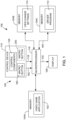
- FIG. 1 is a simplified block diagram of an exemplary game system 100 in accordance with embodiments.
- the game system comprises a video game application 102 stored in memory 104A, a display 106 and a control system 108.
- the control system 108 includes a control device 110, a driver program 112 stored in memory 104B, view change settings 114 stored in memory 104C and a microprocessor or central processing unit 116.
- the microprocessor 116 represents one or more devices that are configured to control the operations of the game system 100 and the control system 108.
- the microprocessor 116 may be a component of a personal computer, a game console (e.g., Xbox 360) or other computing device.
- Exemplary operations that could be performed by the microprocessor 116 include data communications in the system 100 including data communications with accessible memory of the system, such as memory 104A, 104B and 104C; network data communications; responses to input signals 118 received from one or more of the control devices 110; the execution of instructions stored on a tangible medium, such as the instructions of the video game application 102 and the driver program 112; the generation of output signals that control one or more output devices, such as a display signal 120 that controls the display 106; and other functions.
- the memories 104A-C represent physical storage mediums that can be separate from each other or combined.
- the physical storage mediums 104A-C can take on many different forms, such as CD-ROM's, digital versatile disks (DVD) or other optical disk storage media, flash memory drives, hard drives, RAM, ROM, EEPROM, magnetic cassettes, magnetic tape, magnetic disk storage or other magnetic storage devices, or any other medium which can be used to store the desired video game application 102, driver program 112 and the view change settings 114.
- the control device 110 may be any suitable input device to the control system 108 for controlling operations of a game character within the game environment of the video game.
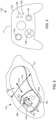
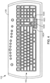
- Embodiments of the control device 110 include a computer mouse 122, a game controller (i.e., a control device that is generally dedicated to gaming) 124 and a keyboard 126, which are respectively illustrated in FIGS. 2-4 .
- the control device 110 includes control components 128 ( FIG. 1 ) that, when actuated, generate the input signals 118.
- the driver program 112 translates the input signals 118 into information that is used by the video game application 102 under the control of the microprocessor 116 to produce an action within the video game, such as movement of the game character or other action.
- Exemplary control components 128 of the mouse 122 include buttons 132, a scroll wheel 134, the mechanical or optical components (not shown) that translate lateral or side-to-side movement of the mouse into movement of the game character, and other components.
- Exemplary control components 128 of the game controller 124 include buttons 136, a directional pad 138, a joystick 140, finger triggers (not shown) and other components.
- Exemplary control components 128 of the keyboard 126 include the keys 142, such as the arrow keys 142A-D, and other components.
- the video game application 102 assigns predefined actions to the control components 128 of the control device 110.
- the actuation of some of the control components 128 results in the execution of the predefined action of the game character, such as a jump or a kick, for example.
- Other movements of the game character in response to actuation of some of the control components 128 include operator or player controlled movements that do not fall into this predefined action category, such as the orientation of the game character's view and the direction and speed at which the game character travels.
- the video game application 102 can comprise any game in which embodiments are useful.
- Exemplary video games include first-person games (e.g., Halo ® , racing games), in which the display 106 presents the player (i.e., the operator of the control device) a view of the game environment as seen by the game character (i.e., human, creature, mechanical device, etc.) he or she controls, and third-person games (e.g., role playing games such as Dungeon Siege ® II), in which the display 106 presents a distant view of the game character within the game environment.
- the game character has a view (hereinafter "character view"), which has a particular orientation.
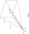
- FIG. 5 illustrates an exemplary view of a portion of a game character 144 within a game environment 146 as produced by the execution of the video game application 102.
- the display 106 presents the view of the game environment 146 as seen by the game character 144, which is represented by the projection 148.
- Objects within the projection 148 that are viewable to the game character 144 are provided on the display 106 of the game system 100.
- the orientation of the character view 144 determines what the player sees on the display 106.
- the display 106 presents the game character 144 (only a portion shown) and the surrounding game environment 146.
- the third-person game character 144 has a "view" of the game environment corresponding to the orientation of the game character's "head” or "eyes", for example.
- movements of the head of the third-person game character 144 results in a movement of the orientation of the game character view.
- the movement of the orientation of the third-person game character view can be important in, for example, role playing games where the game character 144 can interact with other objects and inhabitants of the game environment 146.
- the interaction between the game character 144 and an object or inhabitant of the game environment 146 is driven, in part, by the orientation of the character view 148 or where the game character is "looking".
- the orientation of the first-person or third-person character view of the game environment 146 can generally be moved using one of the control components 128 of the control device 110.
- the orientation 150 of the character view can rotate about a vertical axis 152 in clockwise and counterclockwise directions, as indicated by the arrow 154 shown in the simplified top plan view of the game character 144 in FIG. 6 .
- the orientation 150 may move from a starting orientation 156 to an ending orientation 158 by rotating the orientation 150 about the vertical axis 152 in the counterclockwise direction indicated by arrow 160, or the clockwise direction.
- orientation 150 of the character view may also pivot upward and downward about an axis 162, as represented by the arrow 164 in the simplified side view of the game character 144 shown in FIG. 7 .
- the orientation 150 may move from a starting orientation 166 to an ending orientation 168 by pivoting the orientation 150 about the vertical axis 152 in the upward direction indicated by arrow 170, as shown in FIG. 6 .
- the movements of the orientation 150 of the character view may also include both the rotation about the vertical axis 152 and the pivoting about the axis 162 in response to the actuation of one or more of the control components 128 of the device 110.
- the orientation 150 of the game character's view can be rotated about the vertical axis 152 and/or pivoted up or down about the axis 162 in response to movements of the mouse across a surface 171.
- movement of the mouse 122 across the surface in the directions indicated by arrow 172 can cause the orientation of the character view to rotate about the axis 152 in either a clockwise or counterclockwise direction.
- movement of the mouse 122 across the surface in the direction indicated by arrow 174 can cause the orientation 150 of the character view to pivot upward or downward.
- the controller is a game controller, such as game controller 124 shown in FIG. 3
- the up, down, clockwise and counterclockwise movements of the orientation of the character view are typically performed in response to movements of the directional pad 138 or the joystick 140, for example.
- control device 110 is a keyboard, such as the keyboard 126 shown in FIG. 4
- the up, down, clockwise and counterclockwise movements of the orientation 150 of the character view are performed in response to actuation of separate keys 142, such as the arrow keys 142A-D, for example.
- the signals 118 produced by the control device 110 in response to actuations of the control components 128 that result in movements of the orientation 150 of the character view generally provide distance and direction information to the driver program 112 in accordance with conventional methods.
- the distance and direction information generally comprises a linear count of distance units in the given direction over a unit of time.
- the driver program 112 translates the distance and direction information from the signals 118 into movement information 184 ( FIG. 1 ) that is used by the microprocessor 116 to move the orientation 150 in the indicated direction in accordance with the video game application 102.
- the driver program 112 translates the signals 118 such that they can be processed to produce a corresponding rotational movement of the orientation 150 of the character view about the one of the axes 152 and 162 in accordance with the video game application 102.
- the signals 118 produced in response to actuation of the key indicate movement in the given direction, a distance and speed of which is based on each strike of the key and/or the duration of time that the key is pressed.
- a distance and speed of which is based on each strike of the key and/or the duration of time that the key is pressed.
- 5 strikes of the key over a period of one second, or depressing and holding the key for 1 second may each constitute 5 units of distance to the driver program 112. That distance and speed is then communicated to the microprocessor 116 which rotates the orientation 150 about the corresponding axis 152 or 162 in accordance with the video game application 102.
- the signals 118 produced in response to such movement of the mouse 122 indicate distances traveled in the directions 170 or 174 in which the mouse 122 is moved.
- the signals 118 also provide speed information based on the distance traveled by the mouse 122 per unit of time. Each unit of distance the mouse 122 travels in a given direction 170 or 174 is translated by the driver program 112 into the movement information 184 that moves the orientation 150 of the character view, as presented on the display 106, an amount and direction as determined by the video game application 102.
- the signals 118 generally indicate a direction in which the pad 138 or joystick 140 is deflected.
- the amount of the deflection from the quiescent state of the pad 138 or joystick 140 can be used to indicate a speed of the desired movement.
- the driver program 112 translates the direction, distance and speed of movement indicated by the signals 118 and provides the resultant movement information 184 to the microprocessor 116, which operates to move the orientation 150 in accordance with the video game application 102.
- the operator rather than having to move the mouse 122 across the surface 171, pressing a button or key for a period of time or a select number of times, or moving a directional pad 138 or joystick 140 in a given direction for a period of time, the operator only needs to press the macro button 180 to execute the player-operated movement of the orientation 150 as defined by the view change settings 114.
- the control device 110 includes the macro button 180.
- Actuation of the macro button 180 produces a macro actuation signal 182 ( FIG. 1 ).
- the macro button 180 is distinct from the control components 128 that are programmed for use during play of the video game application 102.
- the driver program 112 produces a view change output 184 (i.e., movement information) in response to the actuation of the macro button 180 and reception of the macro actuation signal 182.
- the view change output 184 is based on the view change settings 114 stored in the memory 104C.
- the microprocessor 116 is configured to move the orientation 150 of the character view of the gaming environment 146 from a beginning orientation 186 to an ending orientation 188 based on the view change settings 114 in response to the view change output 184, as illustrated in the simplified plan view of a game character 144 provided in FIG. 8 .
- the view change output 184 which is based on the view change settings 114, mirrors the signal or information that would have been generated by the driver program 112 in response to the actuation of the control components 128 of the control device 110 that the player would have performed in order to move the orientation 150 from the beginning orientation 186 to the ending orientation 188.
- the amount and direction that the orientation 150 moves in response to the actuation of the macro button 180 is determined, at least in part, by the view change settings 114. Additional embodiments of the control system 108 will be described in combination with embodiments of the method illustrated in FIG. 9 .
- FIG. 9 is a flowchart illustrating a method of using a control system, such as control system 108, to move an orientation 150 of a character view of a gaming environment 146 in a video game, in accordance with embodiments.
- the method steps are generally performed in response to execution of instructions of the driver program 112 and the video game application 102 respectively stored in the tangible mediums represented by memories 104B and 104A, respectively, by the microprocessor 116.
- a view orientation move is calibrated including storing the view change settings 114 in memory 104C ( FIG. 1 ).
- the view change output 184 is produced in response to the actuation of the macro button 180 or reception of the actuation output signal 182.
- the orientation 150 of the character view of the gaming environment 146 is moved, at step 204, from the beginning orientation 186 to the ending orientation 188 based on the view change settings 114 in response to the view change output 184, as mentioned above and illustrated in the simplified plan view of a game character 144 provided in FIG. 8 .
- the movement of the orientation 150 is generally a rotation about an axis 210, as indicated by arrow 211. The direction of the rotation is determined by the view change settings 114.
- the beginning orientation 186 corresponds to the orientation 150 of the character view during game play when the macro button 180 is actuated.
- the orientation 150 then moves to the ending orientation 188, based on the view change settings 114, during play of the video game 102.
- the axis 210 represents one or more axes about which the control components 128 of the control device 110 are configured to rotate the orientation 150 of the character view.
- the movements described below may alternatively involve a rotation about the horizontal axis 162 alone, or simultaneous rotations about the vertical and horizontal axes 152 and 162, based on the signals 118 produced by the control device 110, for example.
- the axis 210 represents a single axis, which may correspond to the vertical axis 152 ( FIG.
- the axis 210 represents a combination of the vertical and the horizontal axes 152 and 162, and the orientation 150 moves or rotates from the beginning orientation 186 to the ending orientation 188 about the axis 210 during step 204.
- the calibration routine is started.
- the calibration routine is started by pressing and holding the macro button 180 and, after a predetermined period of time, releasing the macro button 180.
- the predetermined period of time is approximately one second or more.
- the calibration routine is started during play of the video game 102.
- the orientation 150 of the character view has a beginning orientation 214, shown in FIG. 11 .
- the orientation 150 of the character view is moved from a beginning orientation 216 to an ending orientation 218 about an axis 220 as indicated by arrow 221 during play of the video game 102, as illustrated in FIG. 11 .
- axis 220 can represent one or more axes about which the control components 128 of the control device 110 are configured to rotate the orientation 150 of the character view.
- the movement of the orientation 150 of the character view in step 214 comprises adjusting the orientation 150 of the character view using a control component 128 of the control device 110 that are generally pre-set to perform the desired movement of the orientation 150 during play of the video game 102.
- the movement of the orientation 150 of the character view is performed without the use of the macro button 180.
- the step 214 can be performed using the control components 128 that are traditionally used to move the orientation 150 of the character view.
- the movement of the orientation 150 can be performed by moving the mouse 122 across the surface 171 in the direction indicated by arrow 170 and/or 174 to move the orientation 150 of the character view during play of the video game 102 from the beginning orientation 216 to the ending orientation 218, as described above.
- Other embodiments include moving the orientation from the beginning orientation 216 to the ending orientation 218 using a game controller 124 ( FIG. 3 ) or a keyboard 126 ( FIG. 4 ), as described above.
- the calibration routine is ended.
- the ending orientation 218 corresponds to the orientation 150 of the character view upon ending the calibration routine.
- the calibration routine is ended by actuating the macro button 180.
- the view change settings 114 are produced based on the movement of the orientation 150 of the character view in step 214 and the view change settings are stored in the memory 104C at step 226.
- the view change settings 114 based on a difference between the beginning orientation 216 and the ending orientation 218. Because the distance and direction information provided by the signals 118 of the control device 110 that correspond to movement of the orientation 150 are generally a linear count of distance units in the given direction over a unit of time, the difference between the first and second orientations can be obtained by simply subtracting the position value of the first orientation from the position value of the second orientation. The sign of the resulting difference indicates the direction in which the orientation 150 was moved.
- the beginning orientation 216 and the ending orientation 218 may have a set angular position relative to a reference 228.
- the difference between the beginning and ending orientations 216 and 218 is equal to the angular position of the ending orientation 218 relative to the reference 228 less the angular position of the beginning orientation 216 relative to the reference 228.
- the movement of the orientation 150 in step 204 following actuation of the macro button 180 matches the movement of the orientation 150 during the moving step 214. That is the view change settings 114 are set to rotate the orientation 150 from the beginning orientation 186 in response to actuation of the macro button 180 by an amount that matches the difference between the beginning and ending orientations 216 and 218 set during the calibration routine.
- the player uses the control component 128 of the control device 110 to move the orientation 150 of the character view about the vertical axis 152 approximately 360. This is helpful when it is desired to have the view change settings 114 indicate 180 degrees and other specific angular turns. For instance, during play of a first-person video game, it may be desired to program the macro button 180 to perform a 180 degree turn to allow the game character 144 to quick take a look behind him or her. However, the game environment 146, in which the game character 144 resides, may make it difficult to determine with any real precision a 180 degree turn from the beginning orientation 216 of the calibration routine. By having the player move the orientation 150 a full 360 degrees from the beginning orientation 216 of the calibration routine, the view change settings 114 can be set to one half the measured movement during the calibration routine to more precisely set the desired 180 degree turn.
- the view change settings 114 are set such that the movement of the orientation 150 in the moving step 204 does not match the difference between the beginning and ending orientations 216 and 218 set during the calibration routine. In one embodiment, the view change settings 114 are set such that the orientation 150 moves a fraction of the difference between the beginning and ending orientations 216 and 218 set during the calibration routine. Embodiments of the fraction include one-fourth, one-half and three-fourths of the difference between the beginning and ending orientations 216 and 218.
- the view change settings 114 produced in step 224 are configured to move the orientation 150 from the beginning orientation 186 one quarter of the 360 degree calibrated turn or approximately 90 degrees to the ending orientation 188 during the moving step 204. This quarter turn allows the player to take a quick look to the side through actuation of the macro button 180.
- the view change settings 114 produced in step 224 are configured to move the orientation 150 from the beginning orientation 186 three quarters or approximately 270 degrees to the ending orientation 188 during the moving step 204.
- This three quarter turn allows the player to look to the opposite side of the game player 144 than that produced by the above-described quarter turn.
- this three quarter turn can be accomplished using the one quarter turn values for the view change settings 114, but with a change in the designated direction, such that the view 150 is moved in the opposite direction than that of the quarter turn described above.
- the orientation 150 of the character view is moved from the ending orientation 188 to the beginning orientation 186, at step 230.
- This generally occurs in response to a view return output contained in the movement information 184 that is generated by the driver program 112.
- the view change output 184 generally mirrors the movement information 184 that would have been generated by the driver program 112 in response to the actuation of the control components 128 of the control device 110 that the player would have performed in order to move the orientation 150 from the ending orientation 188 to the beginning orientation 186.
- the view change output 184 is generated in response to a subsequent actuation of the macro button 180. That is, following a first actuation of the macro button 180, which triggers the moving step 204, a second actuation of the macro button 180 triggers the moving step 230 and the microprocessor 116 moves the orientation 150 from the ending orientation 188 to the beginning orientation 186.
- the view change output 184 is generated automatically by the driver program 112 after a predetermined period of time following the moving step 204.
- the orientation 150 moves from the beginning orientation 186 to the ending orientation 188.
- the microprocessor 116 moves the orientation 150 from the ending orientation 188 back to the beginning orientation 186.
- the actuation of the macro button 180 to trigger the moving step 204 comprises pressing and holding the macro button 180. That is, the pressing and holding of the macro button 180 causes the production of the view change output (movement information 184), which in turn causes the microprocessor 116 to move the orientation 150 from the beginning orientation 186 to the ending orientation 188. While the macro button 180 is held, the orientation 150 remains substantially in the ending orientation 188, unless possibly adjusted through actuation of one of the control components 128 of the control device 110. The release of the macro button 180 causes the driver program 112 to produce the view return output (movement information 184) and the microprocessor 116 responds by moving the orientation 150 from the ending orientation 188 to the beginning orientation 186, in accordance with step 230.
- the driver program 112 comprises instructions executable by the microprocessor 116 to generate a graphical user interface, which can be used by the player to configure the quick turn settings.
- FIG. 13 is a simplified diagram of a graphical user interface 240 in accordance with various embodiments.
- One embodiment of the interface 240 includes turn fraction settings 242.
- One embodiment of the turn fraction settings 242 includes one or more fractions of quick turn that was calibrated during the calibrating step 200 ( FIG. 9 ). Exemplary embodiments of the fractions include a one quarter turn 242A, a one half turn 242B, and a three quarters turn 242C. The user may select the desired turn fraction setting 242 by selecting the box 244 adjacent the desired turn.
- the player performs a 360 degree calibration turn during the calibrating step 200, the player can quickly select whether the quick turn (step 204) that is executed in response to actuation of the macro button 180 will be a 90 degree turn, a 180 degree turn, or a 270 degree turn by selecting the corresponding box 244 in the interface 240.
- the speed at which the quick turn (step 204) is executed is automatically set to the speed at which it was performed by the player during the calibration routine (step 200). In another embodiment, the speed at which the quick turn (step 204) is executed is automatically set to a predefined value.
- the speed at which the quick turn (step 204) is execute is user-selectable.
- the graphical user interface 240 includes a turn speed setting 245 where the user may select the desired speed at which the quick turn is performed.
- the turn speed setting 245 comprises a slide bar 246 that is adjustable between slow and fast speed settings.
- Other embodiments include the display of discrete speed settings, such as "slow", "normal” and "fast” (not shown).
- the user may select a direction in which the quick turn is performed about the axis 210 ( FIG. 8 ).
- the direction options are provided in the graphical user interface 240 where the user may select the quick turn to be performed to the left or counterclockwise direction by selecting box 248A or to the right or clockwise direction by selecting box 248B.
- the control device 110 includes a plurality of macro buttons, such as macro button 180 and macro button 250, shown in FIG. 1 .
- Each of the macro buttons generally operates in accordance with the embodiments described above.
- the macro buttons 180 and 250 comprise a macro button pair, in which the actuation of the macro button 180 results in the quick turn (steps 202 and 204) to be performed in the clockwise direction about the axis 210 ( FIG. 8 ) and the actuation of the macro button 250 results in the quick turn to be performed in the counterclockwise direction about the axis 210.
- the scroll wheel 134 of the mouse 122 ( FIG. 2 ) operates as a tilt wheel in which it can be moved either left or right, as indicated by arrow 252, about an axis that is approximately in line with arrow 174.
- the movement of the wheel 134 to the left actuates an interior button 254 and movement of the wheel 134 to the right actuates an interior button 256.
- the interior buttons 254 and 256 are designated as a macro button pair.
- Actuation of the left button 254 triggers the quick turn (steps 202 and 204) to move the orientation 150 from the beginning orientation 186 to the ending orientation 188 in one direction (e.g., left) while the actuation of the right button 256 triggers the quick turn to move the orientation 150 from the beginning orientation 186 to the ending orientation 188 in the opposite direction (e.g., right).
Landscapes
- Engineering & Computer Science (AREA)
- Multimedia (AREA)
- Human Computer Interaction (AREA)
- Processing Or Creating Images (AREA)
- Position Input By Displaying (AREA)
- Digital Computer Display Output (AREA)
- User Interface Of Digital Computer (AREA)
Applications Claiming Priority (2)
| Application Number | Priority Date | Filing Date | Title |
|---|---|---|---|
| US11/893,881 US8142286B2 (en) | 2007-08-17 | 2007-08-17 | Programmable movement of an orientation of a game character view of a game environment |
| PCT/US2008/072919 WO2009026054A2 (en) | 2007-08-17 | 2008-08-12 | Programmable movement of an orientation of a game character view of a game environment |
Publications (3)
| Publication Number | Publication Date |
|---|---|
| EP2185257A2 EP2185257A2 (en) | 2010-05-19 |
| EP2185257A4 EP2185257A4 (en) | 2015-01-28 |
| EP2185257B1 true EP2185257B1 (en) | 2024-09-25 |
Family
ID=40363399
Family Applications (1)
| Application Number | Title | Priority Date | Filing Date |
|---|---|---|---|
| EP08827884.1A Active EP2185257B1 (en) | 2007-08-17 | 2008-08-12 | Programmable movement of an orientation of a game character view of a game environment |
Country Status (8)
| Country | Link |
|---|---|
| US (1) | US8142286B2 (enExample) |
| EP (1) | EP2185257B1 (enExample) |
| JP (1) | JP5462165B2 (enExample) |
| KR (1) | KR101498316B1 (enExample) |
| CN (1) | CN101778656B (enExample) |
| CA (1) | CA2693824C (enExample) |
| TW (1) | TWI430824B (enExample) |
| WO (1) | WO2009026054A2 (enExample) |
Families Citing this family (15)
| Publication number | Priority date | Publication date | Assignee | Title |
|---|---|---|---|---|
| US10912991B2 (en) * | 2009-12-09 | 2021-02-09 | Sony Interactive Entertainment LLC | Portable game controller settings |
| KR101102889B1 (ko) * | 2010-05-20 | 2012-01-10 | 송대진 | 매크로 기능을 구비한 대전 격투 게임용 조이스틱 장치 및 이를 이용한 게임 매크로 방법 |
| WO2012093964A1 (en) * | 2011-01-05 | 2012-07-12 | Razer (Asia-Pacific) Pte Ltd | Systems and methods for managing, selecting, and updating visual interface content using display-enabled keyboards, keypads, and/or other user input devices |
| JP6117464B2 (ja) | 2011-10-11 | 2017-04-19 | 任天堂株式会社 | ゲームシステム、ゲーム処理方法、ゲームプログラム、およびゲーム装置 |
| JP5829090B2 (ja) * | 2011-10-11 | 2015-12-09 | 任天堂株式会社 | ゲームシステム、ゲーム処理方法、ゲームプログラム、およびゲーム装置 |
| US9302182B2 (en) | 2012-05-23 | 2016-04-05 | Side-Kick Ltd | Method and apparatus for converting computer games between platforms using different modalities |
| US9017168B2 (en) * | 2013-05-31 | 2015-04-28 | Cheng Uei Precision Industry Co., Ltd. | Button structure for game controller |
| CN107823882B (zh) * | 2017-11-17 | 2021-05-11 | 网易(杭州)网络有限公司 | 信息处理方法、装置、电子设备及存储介质 |
| CN108211350B (zh) * | 2017-12-07 | 2021-06-04 | 网易(杭州)网络有限公司 | 信息处理方法、电子设备及存储介质 |
| US11890533B2 (en) * | 2018-10-19 | 2024-02-06 | Hit Box, L.L.C. | Ergonomic game controller and system |
| CN111589127B (zh) * | 2020-04-23 | 2022-07-12 | 腾讯科技(深圳)有限公司 | 虚拟角色的控制方法、装置、设备及存储介质 |
| US11458388B1 (en) * | 2020-08-19 | 2022-10-04 | Electronic Arts Inc. | Automated controller configuration recommendation system |
| CN112870712B (zh) | 2021-01-22 | 2023-03-14 | 腾讯科技(深圳)有限公司 | 虚拟场景中画面展示方法、装置、计算机设备及存储介质 |
| CN113680070B (zh) * | 2021-08-26 | 2024-08-09 | 网易(杭州)网络有限公司 | 虚拟交互对象浏览方法、装置、电子设备及存储介质 |
| US20240108982A1 (en) * | 2022-09-30 | 2024-04-04 | Activision Publishing, Inc. | Systems and Methods for Improved Corner Slicing in a Multiplayer Video Game |
Citations (1)
| Publication number | Priority date | Publication date | Assignee | Title |
|---|---|---|---|---|
| US20060040740A1 (en) * | 2004-08-23 | 2006-02-23 | Brain Box Concepts, Inc. | Video game controller |
Family Cites Families (47)
| Publication number | Priority date | Publication date | Assignee | Title |
|---|---|---|---|---|
| US5259626A (en) * | 1992-08-07 | 1993-11-09 | Std Electronic International Ltd. | Programmable video game controller |
| CA2163316A1 (en) * | 1994-11-21 | 1996-05-22 | Roger L. Collins | Interactive play with a computer |
| JP2845175B2 (ja) * | 1995-08-25 | 1999-01-13 | 株式会社オプテック | ゲーム機用コントローラ |
| US6283857B1 (en) * | 1996-09-24 | 2001-09-04 | Nintendo Co., Ltd. | Three-dimensional image processing apparatus with enhanced automatic and user point of view control |
| US6155926A (en) * | 1995-11-22 | 2000-12-05 | Nintendo Co., Ltd. | Video game system and method with enhanced three-dimensional character and background control |
| US6139433A (en) * | 1995-11-22 | 2000-10-31 | Nintendo Co., Ltd. | Video game system and method with enhanced three-dimensional character and background control due to environmental conditions |
| US6127990A (en) | 1995-11-28 | 2000-10-03 | Vega Vista, Inc. | Wearable display and methods for controlling same |
| US6532001B1 (en) | 1996-04-10 | 2003-03-11 | Snap-On Technologies, Inc. | Mouse control for scrolling switch options through screen icon for the switch |
| US5929844A (en) * | 1996-05-03 | 1999-07-27 | First Person Gaming, Inc. | First person perspective control system |
| JPH1094676A (ja) * | 1996-09-20 | 1998-04-14 | Konami Co Ltd | 対戦型ゲームシステムにおける画像表示方法及びゲームシステム |
| US6139434A (en) * | 1996-09-24 | 2000-10-31 | Nintendo Co., Ltd. | Three-dimensional image processing apparatus with enhanced automatic and user point of view control |
| JPH10137445A (ja) * | 1996-11-07 | 1998-05-26 | Sega Enterp Ltd | ゲーム装置、画像音響処理装置および記録媒体 |
| US6280323B1 (en) * | 1996-11-21 | 2001-08-28 | Konami Co., Ltd. | Device, method and storage medium for displaying penalty kick match cursors in a video soccer game |
| JP3103322B2 (ja) * | 1997-05-23 | 2000-10-30 | コナミ株式会社 | シューティングゲーム装置、シューティングゲームの画像表示方法及び可読記録媒体 |
| JP4035867B2 (ja) * | 1997-09-11 | 2008-01-23 | 株式会社セガ | 画像処理装置及び画像処理方法並びに媒体 |
| US6213880B1 (en) | 1997-11-14 | 2001-04-10 | Creative Technology, Ltd. | Game pad apparatus and method for navigation on a digital video disk (DVD) system |
| US6068554A (en) * | 1997-11-25 | 2000-05-30 | Tyler; Kelly D. | Hand manipulated dual controller assembly |
| JP3824788B2 (ja) * | 1998-09-28 | 2006-09-20 | 株式会社コナミデジタルエンタテインメント | ビデオゲーム装置、ビデオゲームにおけるゲーム画面の視点切替方法及びビデオゲームにおけるゲーム画面の視点切替プログラムが記録されたコンピュータ読み取り可能な記録媒体 |
| JP3817385B2 (ja) | 1999-03-11 | 2006-09-06 | インターナショナル・ビジネス・マシーンズ・コーポレーション | マウスポインタの表示方法 |
| US6273818B1 (en) * | 1999-10-25 | 2001-08-14 | Square Co., Ltd. | Video game apparatus and method and storage medium |
| JP3359013B2 (ja) * | 1999-11-30 | 2002-12-24 | 株式会社ナムコ | ゲームシステム及び情報記憶媒体 |
| JP3413383B2 (ja) * | 2000-02-17 | 2003-06-03 | 株式会社ナムコ | ゲームシステム及び情報記憶媒体 |
| JP2001269482A (ja) * | 2000-03-24 | 2001-10-02 | Konami Computer Entertainment Japan Inc | ゲームシステム、ゲーム用プログラムを記録したコンピュータ読み取り可能な記録媒体及び画像表示方法 |
| US6741233B1 (en) * | 2000-04-28 | 2004-05-25 | Logitech Europe S.A. | Roller functionality in joystick |
| US7137891B2 (en) | 2001-01-31 | 2006-11-21 | Sony Computer Entertainment America Inc. | Game playing system with assignable attack icons |
| US7079110B2 (en) | 2001-04-30 | 2006-07-18 | Microsoft Corporation | Input device including a wheel assembly for scrolling an image in multiple directions |
| US6727889B2 (en) | 2001-09-14 | 2004-04-27 | Stephen W. Shaw | Computer mouse input device with multi-axis palm control |
| US20030224332A1 (en) | 2002-05-31 | 2003-12-04 | Kirill Trachuk | Computerized battle-control system/game (BCS) |
| JP3990252B2 (ja) * | 2002-10-15 | 2007-10-10 | 株式会社バンダイナムコゲームス | ゲームシステム、プログラム及び情報記憶媒体 |
| KR100490726B1 (ko) | 2002-10-17 | 2005-05-24 | 한국전자통신연구원 | 비디오 기반의 사격 게임 장치 및 그 방법 |
| US6989818B2 (en) * | 2002-11-07 | 2006-01-24 | Electro Source, Inc. | Input controller for a game system having a combination move feature |
| US7274365B1 (en) | 2003-01-31 | 2007-09-25 | Microsoft Corporation | Graphical processing of object perimeter information |
| US7075516B2 (en) | 2003-03-07 | 2006-07-11 | Microsoft Corporation | Scroll wheel assembly for scrolling an image in multiple directions |
| JP2004281013A (ja) * | 2003-03-19 | 2004-10-07 | Hitachi Ltd | 音楽情報の検索・再生システム |
| JP2004325828A (ja) * | 2003-04-25 | 2004-11-18 | Namco Ltd | シミュレータ、プログラム及び情報記憶媒体 |
| US7187362B2 (en) | 2003-09-26 | 2007-03-06 | Hui-Hu Liang | Hot-key mouse for the same |
| KR20050091232A (ko) * | 2004-03-11 | 2005-09-15 | 삼성전자주식회사 | 전자 기기 제어 장치 및 방법 |
| CN1676186A (zh) * | 2004-03-29 | 2005-10-05 | 英泰克公司 | 带有集成的轨迹球控制装置的电子游戏操纵器 |
| US20050215321A1 (en) | 2004-03-29 | 2005-09-29 | Saied Hussaini | Video game controller with integrated trackball control device |
| US20050225531A1 (en) | 2004-04-13 | 2005-10-13 | Annie Cheng | Horizontal scrolling mouse |
| US20060250351A1 (en) * | 2004-09-21 | 2006-11-09 | Fu Peng C | Gamepad controller mapping |
| US7346851B2 (en) | 2004-11-03 | 2008-03-18 | Lenovo Singapore Pte. Ltd. | System and method for improved scroll mouse operation |
| JP4839615B2 (ja) * | 2004-12-29 | 2011-12-21 | 株式会社セガ | ゲーム装置、ゲームプログラム、ゲームシステム |
| US9566522B2 (en) * | 2005-05-27 | 2017-02-14 | Nokia Technologies Oy | Device, method, and computer program product for customizing game functionality using images |
| US7808480B2 (en) | 2005-10-28 | 2010-10-05 | Sap Ag | Method and system for secure input |
| JP3934660B1 (ja) * | 2006-01-19 | 2007-06-20 | 株式会社コナミデジタルエンタテインメント | ビデオゲームプログラム、ビデオゲーム装置及びビデオゲーム制御方法 |
| US8277316B2 (en) * | 2006-09-14 | 2012-10-02 | Nintendo Co., Ltd. | Method and apparatus for using a common pointing input to control 3D viewpoint and object targeting |
-
2007
- 2007-08-17 US US11/893,881 patent/US8142286B2/en active Active
-
2008
- 2008-08-12 CN CN2008801034313A patent/CN101778656B/zh active Active
- 2008-08-12 EP EP08827884.1A patent/EP2185257B1/en active Active
- 2008-08-12 JP JP2010521122A patent/JP5462165B2/ja active Active
- 2008-08-12 WO PCT/US2008/072919 patent/WO2009026054A2/en not_active Ceased
- 2008-08-12 CA CA2693824A patent/CA2693824C/en active Active
- 2008-08-12 KR KR1020107003162A patent/KR101498316B1/ko active Active
- 2008-08-15 TW TW097131280A patent/TWI430824B/zh active
Patent Citations (1)
| Publication number | Priority date | Publication date | Assignee | Title |
|---|---|---|---|---|
| US20060040740A1 (en) * | 2004-08-23 | 2006-02-23 | Brain Box Concepts, Inc. | Video game controller |
Also Published As
| Publication number | Publication date |
|---|---|
| CN101778656B (zh) | 2013-04-03 |
| KR20100046192A (ko) | 2010-05-06 |
| CA2693824A1 (en) | 2009-02-26 |
| US20090048018A1 (en) | 2009-02-19 |
| TW200924825A (en) | 2009-06-16 |
| TWI430824B (zh) | 2014-03-21 |
| EP2185257A4 (en) | 2015-01-28 |
| JP5462165B2 (ja) | 2014-04-02 |
| EP2185257A2 (en) | 2010-05-19 |
| CN101778656A (zh) | 2010-07-14 |
| WO2009026054A2 (en) | 2009-02-26 |
| WO2009026054A3 (en) | 2009-04-23 |
| KR101498316B1 (ko) | 2015-03-09 |
| CA2693824C (en) | 2015-11-03 |
| US8142286B2 (en) | 2012-03-27 |
| JP2010536428A (ja) | 2010-12-02 |
Similar Documents
| Publication | Publication Date | Title |
|---|---|---|
| EP2185257B1 (en) | Programmable movement of an orientation of a game character view of a game environment | |
| US6139434A (en) | Three-dimensional image processing apparatus with enhanced automatic and user point of view control | |
| US7762891B2 (en) | Game apparatus, recording medium having game program recorded thereon, and game system | |
| US6322444B1 (en) | Video game with displayed bar for indicating target position | |
| JP6770598B2 (ja) | ゲームプログラム、方法、および情報処理装置 | |
| KR20110122741A (ko) | 사용자가 다양한 신체 위치를 취할 것을 요구하는 신체 위치 검출기를 갖는 컴퓨터 비디오게임 시스템 | |
| KR20140052033A (ko) | 카지노 게이밍 햅틱을 위한 시스템 및 방법 | |
| EP3796988B1 (en) | Virtual camera placement system | |
| US7967680B2 (en) | Storage medium having game program stored thereon and game apparatus | |
| WO2008026382A1 (en) | Game machine, game machine control method, and information storage medium | |
| JP6057738B2 (ja) | ゲームプログラム、ゲーム装置、ゲームシステム、およびゲーム処理方法 | |
| EP2124141B1 (en) | Information processing device, control method for information processing device, and information storage medium | |
| JP7305599B2 (ja) | プログラム | |
| WO2006096256A1 (en) | In-game shot aiming indicator | |
| JP2002085827A (ja) | ゲーム画面表示方法、記録媒体及びゲーム装置 | |
| JP7506102B2 (ja) | プログラム、情報処理装置および情報処理方法 | |
| EP1557747B1 (en) | Object selecting method | |
| JP4181200B2 (ja) | ビデオゲーム処理装置、およびビデオゲーム処理プログラム | |
| JP2009247456A (ja) | タッチパネルを備えたゲーム機 | |
| US20250242246A1 (en) | Video game controller overlay to visually indicate video game player's physical controls | |
| JP7000408B2 (ja) | ゲーム装置、ゲーム処理方法及びプログラム | |
| JP7457753B2 (ja) | プログラム、および情報処理装置 | |
| JP7062033B2 (ja) | 情報処理プログラム、情報処理装置、情報処理システム、および情報処理方法 | |
| JP2011142959A (ja) | ゲーム装置、ゲーム装置の制御方法及びプログラム | |
| JP2023147546A (ja) | コンピュータシステム、ゲームシステムおよびプログラム |
Legal Events
| Date | Code | Title | Description |
|---|---|---|---|
| PUAI | Public reference made under article 153(3) epc to a published international application that has entered the european phase |
Free format text: ORIGINAL CODE: 0009012 |
|
| 17P | Request for examination filed |
Effective date: 20100310 |
|
| AK | Designated contracting states |
Kind code of ref document: A2 Designated state(s): AT BE BG CH CY CZ DE DK EE ES FI FR GB GR HR HU IE IS IT LI LT LU LV MC MT NL NO PL PT RO SE SI SK TR |
|
| AX | Request for extension of the european patent |
Extension state: AL BA MK RS |
|
| DAX | Request for extension of the european patent (deleted) | ||
| A4 | Supplementary search report drawn up and despatched |
Effective date: 20150108 |
|
| RIC1 | Information provided on ipc code assigned before grant |
Ipc: A63F 13/525 20140101ALI20141222BHEP Ipc: A63F 13/40 20140101AFI20141222BHEP Ipc: G06F 17/00 20060101ALI20141222BHEP |
|
| RAP1 | Party data changed (applicant data changed or rights of an application transferred) |
Owner name: MICROSOFT TECHNOLOGY LICENSING, LLC |
|
| STAA | Information on the status of an ep patent application or granted ep patent |
Free format text: STATUS: EXAMINATION IS IN PROGRESS |
|
| 17Q | First examination report despatched |
Effective date: 20181031 |
|
| RIC1 | Information provided on ipc code assigned before grant |
Ipc: A63F 13/40 20140101AFI20141222BHEP Ipc: A63F 13/525 20140101ALI20141222BHEP Ipc: G06F 17/00 20190101ALI20141222BHEP |
|
| RAP3 | Party data changed (applicant data changed or rights of an application transferred) |
Owner name: MICROSOFT TECHNOLOGY LICENSING, LLC |
|
| GRAP | Despatch of communication of intention to grant a patent |
Free format text: ORIGINAL CODE: EPIDOSNIGR1 |
|
| STAA | Information on the status of an ep patent application or granted ep patent |
Free format text: STATUS: GRANT OF PATENT IS INTENDED |
|
| INTG | Intention to grant announced |
Effective date: 20240417 |
|
| P01 | Opt-out of the competence of the unified patent court (upc) registered |
Effective date: 20240502 |
|
| GRAS | Grant fee paid |
Free format text: ORIGINAL CODE: EPIDOSNIGR3 |
|
| GRAA | (expected) grant |
Free format text: ORIGINAL CODE: 0009210 |
|
| STAA | Information on the status of an ep patent application or granted ep patent |
Free format text: STATUS: THE PATENT HAS BEEN GRANTED |
|
| AK | Designated contracting states |
Kind code of ref document: B1 Designated state(s): AT BE BG CH CY CZ DE DK EE ES FI FR GB GR HR HU IE IS IT LI LT LU LV MC MT NL NO PL PT RO SE SI SK TR |
|
| REG | Reference to a national code |
Ref country code: GB Ref legal event code: FG4D |
|
| REG | Reference to a national code |
Ref country code: CH Ref legal event code: EP |
|
| REG | Reference to a national code |
Ref country code: DE Ref legal event code: R096 Ref document number: 602008065103 Country of ref document: DE |
|
| REG | Reference to a national code |
Ref country code: IE Ref legal event code: FG4D |
|
| REG | Reference to a national code |
Ref country code: NL Ref legal event code: FP |
|
| REG | Reference to a national code |
Ref country code: LT Ref legal event code: MG9D |
|
| PG25 | Lapsed in a contracting state [announced via postgrant information from national office to epo] |
Ref country code: NO Free format text: LAPSE BECAUSE OF FAILURE TO SUBMIT A TRANSLATION OF THE DESCRIPTION OR TO PAY THE FEE WITHIN THE PRESCRIBED TIME-LIMIT Effective date: 20241225 |
|
| PG25 | Lapsed in a contracting state [announced via postgrant information from national office to epo] |
Ref country code: GR Free format text: LAPSE BECAUSE OF FAILURE TO SUBMIT A TRANSLATION OF THE DESCRIPTION OR TO PAY THE FEE WITHIN THE PRESCRIBED TIME-LIMIT Effective date: 20241226 Ref country code: FI Free format text: LAPSE BECAUSE OF FAILURE TO SUBMIT A TRANSLATION OF THE DESCRIPTION OR TO PAY THE FEE WITHIN THE PRESCRIBED TIME-LIMIT Effective date: 20240925 |
|
| PG25 | Lapsed in a contracting state [announced via postgrant information from national office to epo] |
Ref country code: BG Free format text: LAPSE BECAUSE OF FAILURE TO SUBMIT A TRANSLATION OF THE DESCRIPTION OR TO PAY THE FEE WITHIN THE PRESCRIBED TIME-LIMIT Effective date: 20240925 |
|
| PG25 | Lapsed in a contracting state [announced via postgrant information from national office to epo] |
Ref country code: LV Free format text: LAPSE BECAUSE OF FAILURE TO SUBMIT A TRANSLATION OF THE DESCRIPTION OR TO PAY THE FEE WITHIN THE PRESCRIBED TIME-LIMIT Effective date: 20240925 |
|
| PG25 | Lapsed in a contracting state [announced via postgrant information from national office to epo] |
Ref country code: NO Free format text: LAPSE BECAUSE OF FAILURE TO SUBMIT A TRANSLATION OF THE DESCRIPTION OR TO PAY THE FEE WITHIN THE PRESCRIBED TIME-LIMIT Effective date: 20241225 Ref country code: LV Free format text: LAPSE BECAUSE OF FAILURE TO SUBMIT A TRANSLATION OF THE DESCRIPTION OR TO PAY THE FEE WITHIN THE PRESCRIBED TIME-LIMIT Effective date: 20240925 Ref country code: GR Free format text: LAPSE BECAUSE OF FAILURE TO SUBMIT A TRANSLATION OF THE DESCRIPTION OR TO PAY THE FEE WITHIN THE PRESCRIBED TIME-LIMIT Effective date: 20241226 Ref country code: FI Free format text: LAPSE BECAUSE OF FAILURE TO SUBMIT A TRANSLATION OF THE DESCRIPTION OR TO PAY THE FEE WITHIN THE PRESCRIBED TIME-LIMIT Effective date: 20240925 Ref country code: BG Free format text: LAPSE BECAUSE OF FAILURE TO SUBMIT A TRANSLATION OF THE DESCRIPTION OR TO PAY THE FEE WITHIN THE PRESCRIBED TIME-LIMIT Effective date: 20240925 |
|
| REG | Reference to a national code |
Ref country code: AT Ref legal event code: MK05 Ref document number: 1726195 Country of ref document: AT Kind code of ref document: T Effective date: 20240925 |
|
| PG25 | Lapsed in a contracting state [announced via postgrant information from national office to epo] |
Ref country code: IS Free format text: LAPSE BECAUSE OF FAILURE TO SUBMIT A TRANSLATION OF THE DESCRIPTION OR TO PAY THE FEE WITHIN THE PRESCRIBED TIME-LIMIT Effective date: 20250125 Ref country code: PT Free format text: LAPSE BECAUSE OF FAILURE TO SUBMIT A TRANSLATION OF THE DESCRIPTION OR TO PAY THE FEE WITHIN THE PRESCRIBED TIME-LIMIT Effective date: 20250127 |
|
| PG25 | Lapsed in a contracting state [announced via postgrant information from national office to epo] |
Ref country code: RO Free format text: LAPSE BECAUSE OF FAILURE TO SUBMIT A TRANSLATION OF THE DESCRIPTION OR TO PAY THE FEE WITHIN THE PRESCRIBED TIME-LIMIT Effective date: 20240925 |
|
| PG25 | Lapsed in a contracting state [announced via postgrant information from national office to epo] |
Ref country code: ES Free format text: LAPSE BECAUSE OF FAILURE TO SUBMIT A TRANSLATION OF THE DESCRIPTION OR TO PAY THE FEE WITHIN THE PRESCRIBED TIME-LIMIT Effective date: 20240925 |
|
| PG25 | Lapsed in a contracting state [announced via postgrant information from national office to epo] |
Ref country code: EE Free format text: LAPSE BECAUSE OF FAILURE TO SUBMIT A TRANSLATION OF THE DESCRIPTION OR TO PAY THE FEE WITHIN THE PRESCRIBED TIME-LIMIT Effective date: 20240925 Ref country code: AT Free format text: LAPSE BECAUSE OF FAILURE TO SUBMIT A TRANSLATION OF THE DESCRIPTION OR TO PAY THE FEE WITHIN THE PRESCRIBED TIME-LIMIT Effective date: 20240925 |
|
| PG25 | Lapsed in a contracting state [announced via postgrant information from national office to epo] |
Ref country code: CZ Free format text: LAPSE BECAUSE OF FAILURE TO SUBMIT A TRANSLATION OF THE DESCRIPTION OR TO PAY THE FEE WITHIN THE PRESCRIBED TIME-LIMIT Effective date: 20240925 Ref country code: PL Free format text: LAPSE BECAUSE OF FAILURE TO SUBMIT A TRANSLATION OF THE DESCRIPTION OR TO PAY THE FEE WITHIN THE PRESCRIBED TIME-LIMIT Effective date: 20240925 |
|
| PG25 | Lapsed in a contracting state [announced via postgrant information from national office to epo] |
Ref country code: IT Free format text: LAPSE BECAUSE OF FAILURE TO SUBMIT A TRANSLATION OF THE DESCRIPTION OR TO PAY THE FEE WITHIN THE PRESCRIBED TIME-LIMIT Effective date: 20240925 Ref country code: SK Free format text: LAPSE BECAUSE OF FAILURE TO SUBMIT A TRANSLATION OF THE DESCRIPTION OR TO PAY THE FEE WITHIN THE PRESCRIBED TIME-LIMIT Effective date: 20240925 |
|
| REG | Reference to a national code |
Ref country code: DE Ref legal event code: R097 Ref document number: 602008065103 Country of ref document: DE |
|
| PG25 | Lapsed in a contracting state [announced via postgrant information from national office to epo] |
Ref country code: DK Free format text: LAPSE BECAUSE OF FAILURE TO SUBMIT A TRANSLATION OF THE DESCRIPTION OR TO PAY THE FEE WITHIN THE PRESCRIBED TIME-LIMIT Effective date: 20240925 |
|
| PLBE | No opposition filed within time limit |
Free format text: ORIGINAL CODE: 0009261 |
|
| STAA | Information on the status of an ep patent application or granted ep patent |
Free format text: STATUS: NO OPPOSITION FILED WITHIN TIME LIMIT |
|
| PGFP | Annual fee paid to national office [announced via postgrant information from national office to epo] |
Ref country code: NL Payment date: 20250723 Year of fee payment: 18 |
|
| 26N | No opposition filed |
Effective date: 20250626 |
|
| PG25 | Lapsed in a contracting state [announced via postgrant information from national office to epo] |
Ref country code: SE Free format text: LAPSE BECAUSE OF FAILURE TO SUBMIT A TRANSLATION OF THE DESCRIPTION OR TO PAY THE FEE WITHIN THE PRESCRIBED TIME-LIMIT Effective date: 20240925 |
|
| PGFP | Annual fee paid to national office [announced via postgrant information from national office to epo] |
Ref country code: DE Payment date: 20250724 Year of fee payment: 18 |
|
| PGFP | Annual fee paid to national office [announced via postgrant information from national office to epo] |
Ref country code: GB Payment date: 20250724 Year of fee payment: 18 |
|
| PGFP | Annual fee paid to national office [announced via postgrant information from national office to epo] |
Ref country code: FR Payment date: 20250723 Year of fee payment: 18 |