EP2184047A1 - Système d'impression de comprimés, procédé de production de comprimés, et comprimés - Google Patents
Système d'impression de comprimés, procédé de production de comprimés, et comprimés Download PDFInfo
- Publication number
- EP2184047A1 EP2184047A1 EP08827968A EP08827968A EP2184047A1 EP 2184047 A1 EP2184047 A1 EP 2184047A1 EP 08827968 A EP08827968 A EP 08827968A EP 08827968 A EP08827968 A EP 08827968A EP 2184047 A1 EP2184047 A1 EP 2184047A1
- Authority
- EP
- European Patent Office
- Prior art keywords
- tablet
- tablets
- printing
- conveying belt
- conveying
- Prior art date
- Legal status (The legal status is an assumption and is not a legal conclusion. Google has not performed a legal analysis and makes no representation as to the accuracy of the status listed.)
- Withdrawn
Links
Images


Classifications
-
- A—HUMAN NECESSITIES
- A61—MEDICAL OR VETERINARY SCIENCE; HYGIENE
- A61J—CONTAINERS SPECIALLY ADAPTED FOR MEDICAL OR PHARMACEUTICAL PURPOSES; DEVICES OR METHODS SPECIALLY ADAPTED FOR BRINGING PHARMACEUTICAL PRODUCTS INTO PARTICULAR PHYSICAL OR ADMINISTERING FORMS; DEVICES FOR ADMINISTERING FOOD OR MEDICINES ORALLY; BABY COMFORTERS; DEVICES FOR RECEIVING SPITTLE
- A61J3/00—Devices or methods specially adapted for bringing pharmaceutical products into particular physical or administering forms
- A61J3/007—Marking tablets or the like
-
- B—PERFORMING OPERATIONS; TRANSPORTING
- B41—PRINTING; LINING MACHINES; TYPEWRITERS; STAMPS
- B41J—TYPEWRITERS; SELECTIVE PRINTING MECHANISMS, i.e. MECHANISMS PRINTING OTHERWISE THAN FROM A FORME; CORRECTION OF TYPOGRAPHICAL ERRORS
- B41J11/00—Devices or arrangements of selective printing mechanisms, e.g. ink-jet printers or thermal printers, for supporting or handling copy material in sheet or web form
- B41J11/007—Conveyor belts or like feeding devices
-
- B—PERFORMING OPERATIONS; TRANSPORTING
- B41—PRINTING; LINING MACHINES; TYPEWRITERS; STAMPS
- B41J—TYPEWRITERS; SELECTIVE PRINTING MECHANISMS, i.e. MECHANISMS PRINTING OTHERWISE THAN FROM A FORME; CORRECTION OF TYPOGRAPHICAL ERRORS
- B41J11/00—Devices or arrangements of selective printing mechanisms, e.g. ink-jet printers or thermal printers, for supporting or handling copy material in sheet or web form
- B41J11/0085—Using suction for maintaining printing material flat
-
- B—PERFORMING OPERATIONS; TRANSPORTING
- B41—PRINTING; LINING MACHINES; TYPEWRITERS; STAMPS
- B41J—TYPEWRITERS; SELECTIVE PRINTING MECHANISMS, i.e. MECHANISMS PRINTING OTHERWISE THAN FROM A FORME; CORRECTION OF TYPOGRAPHICAL ERRORS
- B41J3/00—Typewriters or selective printing or marking mechanisms characterised by the purpose for which they are constructed
- B41J3/407—Typewriters or selective printing or marking mechanisms characterised by the purpose for which they are constructed for marking on special material
Definitions
- the present invention relates to a tablet printing apparatus and a tablet production method, and a tablet, and more particularly to a tablet printing apparatus and a tablet production method for printing on tablets, and a tablet subjected to printing.
- one-dose preparation of two or more types of tablets may be made for patients who take a plurality of types of tablets at the same time.
- identifying information such as a product name is indicated on a surface of a tablet
- a pharmacist takes out tablets from a PTP (Press Through Package)
- PTP Pressure Through Package
- a patient side has also demanded facilitation of discriminating tablets by themselves since improper dose can be avoided if tablets can be easily discriminated even after the tablets are taken out from the PTP.
- identifying information indicated on the tablet surface can be made clear by performing printing with an ink different from a color tone of a tablet. Therefore, the discrimination of the tablet alone can be improved as compared with the above-described marking, whereby a medical error due to improper dosing of medicines hardly occurs.
- the offset printing is carried out in a contact scheme that an intermediate transcript is pressed against a tablet to print identifying information
- the identifying information can be clearly printed on a coating tablet having a film-coated tablet surface.
- printed identifying information partially suffers a loss or the like due to, e.g., a powder that has adhered to the surface, and clear printing is difficult.
- a powder on the surface of the core tablet attaches to the intermediate transcript, clogging of the identifying information engraved on a print surface occurs, which may result in a printing error.
- a core tablet especially a fast-disintegrating tablet (e.g., an orally-disintegrating tablet) formed without being tableted or formed with a small tableting pressure has low tablet hardness and easily disintegrates under a pressure from the outside, whereby the tablet may possibly disintegrate under a pressure when pressing the intermediate transcript. Therefore, a printing technology for tablets based on a non-contact scheme has been previously studied/developed.
- a fast-disintegrating tablet e.g., an orally-disintegrating tablet
- Patent Documents 1 to 3 a technology for discharging an ink to a surface of a tablet by using an inkjet printer to print identifying information on the surface of the tablet has been conventionally proposed (see, e.g., Patent Documents 1 to 3). Further, although a specific method is not disclosed, a method for marking on a surface of a tablet having a non-compressed porous reticulated structure by using an inkjet printer has been also proposed (see Patent Document 2). According to the technologies disclosed in these documents, printing identifying information such as a product name on a tablet surface by discharging an edible ink from an inkjet printer is disclosed. When the tablet printing can be performed by the inkjet printer in a non-contact manner as described above, limiting an influence of a powder that has adhered to the tablet surface to enable clear printing is expected as compared with the conventional offset printing.
- Patent Document 1 proposes supplying many tablets to a feed conveyor from a tablet moving board, mounting the tablets on this feed conveyor in a linearly aligned state, detecting a flow of the tablets by using a sensor, and discharging an ink at a timing that the tablets passes a position near inject nozzles to perform printing on the tablets.
- the tablets supplied from the tablet moving board do not have to be aligned on the feed conveyor at fixed intervals, the tablets are conveyed at a irregular intervals at a timing of supplying the tablets from the tablet moving board and detected by the sensor even though the tablets are irregularly aligned, and an ink discharge timing is controlled, thereby assuredly printing on the tablets with the ink.
- randomly mounting the tablets on the feed conveyor to be carried and immediately carrying the tablets without producing a tablet movement standby period when supplying the tablets from the tablet moving board to the feed conveyor is proposed.
- Patent Document 1 proposes sucking tablets from an air path in a concave portion of a rotary drum, emitting an ink from jet nozzles to perform printing on the tablets, providing concave portions aligned in a plurality of columns as shown in FIG. 6 , and aligning the jet nozzles in parallel in accordance with the concave portions to enable printing.
- Patent Document 1 uses the rotary drum, and a technology for holding tablets in the concave portion previously formed in the rotary drum is proposed.
- the technology for holding the tablets in the concave portion formed in this rotary drum the tablets carried in an irregular state must be previously aligned so that they can regularly enter the concave portion in the rotary drum. It is, therefore, difficult to cope with many tablets in many irregular carriage states, and the technology shown in FIGS. 5 and 6 of Patent Document 1 for performing many types of printing at the same time cannot be applied in irregular carriage states such as depicted in FIGS. 2 and 3 of Patent Document 1.
- a tablet printing apparatus comprising: tablet conveying means that has a case body having an opening at an upper portion thereof, a slit plate arranged on the opening of the case body, a conveying path including a conveying belt that has a slit communicating with the inside of the case body formed between belts arranged in parallel along a slit of the slit plate and that conveys tablets, driving means for moving the conveying belt constituting the conveying path, and negative pressure means for forming a negative pressure in the case body, and that conveys the tablets in a moving direction in a state where the tablets are sucked and held on the conveying belt through both the slits by the negative pressure in the case body; position detecting means for detecting positions of the tablets conveyed by the tablet conveying means on the conveying belt by using a tablet sensor that detects the tablets and an encoder that detects a moving state of the conveying belt irrespective of a moving speed of the conveying belt; printing means for performing
- the printing means for performing printing on the tablet in the non-contact manner is provided, a hiatus of printing or the like is hardly produced and clear printing can be effected even on a tablet (e.g., a core tablet) having a powder adhered to a surface thereof as compared with conventional contact offset printing. Further, since the plurality of printer heads are provided, a large amount of printing can be carried out at a high speed.
- the tablet printing apparatus of the present invention since the tablet can be conveyed while being adsorbed and held, the tablet can be conveyed at a high speed in a state that displacement of the tablet hardly occurs. Therefore, clear printing without distortion can be performed at a fixed position on the tablet surface without causing displacement or the like at a printing position provided by the printing means. That is, since the tablet is sucked and held through the slit of the conveying belt, displacement, dropping, and others of the tablet hardly occurs with respect to the conveying belt. Therefore, the tablet can be conveyed at a high speed, and accurate printing can be effected.
- the line head scheme that the printer heads are arranged and fixed in parallel along a perpendicular direction of a moving direction with respect to the tablet conveying means and they are arranged in parallel along a perpendicular direction of a moving direction of the tablet, the heads do not have to be moved as different from a serial head scheme, and a speed of print processing can be increased. Additionally, since the plurality of printer heads are arranged in parallel along the perpendicular direction of the moving direction of the tablet, appropriately increasing or decreasing the number of arranged printer heads enables performing printing with a desired width.
- the plurality of nozzle holes for discharging inks are aligned at a slant with respect to the moving direction of the tablet, the number of the nozzle holes in the perpendicular direction of the moving direction can be increased, thereby improving a printing resolution.
- the tablet sensor senses the tablet and the encoder detects a moving position of the tablet conveying means
- a position detected by the tablet sensor is determined as a reference, and a current moving position of the tablet can be acquired. Therefore, even if a speed of the tablet conveying means changes, a moving state or a position of the tablet can be accurately acquired, and the printing means is used for executing printing control based on a position of the tablet on the conveying belt detected by the position detecting means, thereby assuredly effecting printing on the tablet.
- the printing controlling means includes an image data memory that stores a master image to be printed on the tablets, a buffer memory that temporarily stores the master image, a write controller that writes the master image into the buffer memory, and a read controller that reads out the master image stored in the buffer memory, the write controller writes the master image into the buffer memory at a timing that the tablets are detected by the tablet sensor, the buffer memory shifts an address at which the master image is stored in the buffer memory in synchronization with a pulse signal from the encoder, and the read controller reads out the master image and outputs it for printing when the master image is stored at a predetermined read address.
- the write controller temporarily stores a master image in the buffer memory at a timing that the tablets are detected by the tablet sensor and shifts an address in the buffer memory at which the master image is stored in synchronization with a pulse signal from the encoder, and the read controller reads the master image and outputs it for printing when the master image is stored at a predetermined read address, whereby an actual moving position of the tablet can be acquired based on a moving position of the tablet conveying means while the position detected by the tablet sensor being determined as a reference. Therefore, even if a speed of the tablet conveying means changes, a position of the tablet can be accurately acquired, and printing on the tablet can be assuredly effected based on this position.
- the tablet conveying means has a plurality of conveying paths along which the tablets are conveyed
- the position detecting means detects moving positions of the tablets in the plurality of respective conveying paths
- the printing controlling means controls a print timing provided by the printing means based on the moving positions of the tablets detected in the plurality of respective conveying paths by the position detecting means.
- the plurality of tablets can be simultaneously conveyed in the different conveying paths, and printing can be effected.
- a throughput for tablet printing can be improved as compared with a case where the tablets are conveyed through a single conveying path.
- a plurality of nozzle hole groups including the plurality of nozzle holes are formed in the printer heads, and the plurality of nozzle hole groups discharge inks having different colors to enable printing in at least two colors.
- polychromic printing can be carried out by discharging from one printer head the inks having colors that differ depending on each nozzle group.
- the tablet can be preferably applied to a core tablet, especially an orally-disintegrating tablet.
- a core tablet especially an orally-disintegrating tablet.
- the core tablet, especially the orally-disintegrating tablet has a large amount of powder on a surface thereof and it is formed with porosity, printing is difficult but, according to the tablet printing apparatus of the present invention, printing can be carried out with respect to such a core tablet, especially the orally-disintegrating tablet.
- the conveying belt can be applied to one that moves at a speed in the range of 500 mm/second to 2000 mm/second. Even if a regular speed is changed to a high speed in this manner, printing appropriate for a moving speed of the conveying belt can be performed by the tablet conveying means, the position detecting means, the printing means, and the printing controlling means as constituent elements of the present invention.
- a tablet printing apparatus comprising: tablet conveying means that has a case body having an opening at an upper portion thereof, a slit plate arranged on the opening of the case body, a conveying path including a conveying belt that has a slit communicating with the inside of the case body formed between belts arranged in parallel along a slit of the slit plate and that conveys tablets, driving means for moving the conveying belt constituting the conveying path, and negative pressure means for forming a negative pressure in the case body, and that conveys the tablets in a moving direction in a state where the tablets are sucked and held on the conveying belt through both the slits by a negative pressure in the case body; position detecting means for detecting positions of the tablets conveyed by the tablet conveying means on the conveying belt by using a tablet sensor that detects the tablets and an encoder that detects a moving state of the conveying belt irrespective of a moving speed of the conveying belt; printing means for performing printing on the tablets
- the printer unit is formed of the plurality of printer heads as the printing means, the plurality of printer units are provided at different positions along the moving direction of the tablet, and the respective printer units discharge the inks of different colors to perform non-contact printing on the tablet conveyed by the tablet conveying means, thus discharging the inks of colors that differ depending on an upstream side and a downstream side of the moving direction.
- ink discharge actuators or nozzle holes of this printer unit must be highly integrated, but arranging the plurality of units at different positions along the moving direction of the tablet like the present invention enables effecting polychromic printing at a high resolution with a simple structure without highly integrating the ink discharge actuators and others.
- a variation of printing colors can be increased as compared with single-color printing.
- the plurality of units are used for polychromic printing, a clear color image can be printed on the tablet at a high speed.
- the objects can be achieved by performing printing on many tablets irregularly conveyed by a conveying belt, the method comprising: a tablet forming step of forming each tablet into a predetermined shape; a tablet conveying step of conveying the tablets in a state where the formed tablets are held on the conveying belt; a position detecting step of detecting positions of the tablets conveyed at the tablet conveying step on the conveying belt by using a tablet sensor that detects the tablets and an encoder that detects a moving state of the conveying belt irrespective of a moving speed of the conveying belt; a printing controlling step of controlling printing on the tablets based on positions of the tablets on the conveying belt detected at the position detecting step; and a printing step of performing printing on the tablets conveyed at the tablet conveying step in a non-contact manner by using a plurality of printer heads that are arranged in parallel and fixed along a perpendicular direction of the moving direction of the conveying belt and have a plurality of nozzle holes for
- the tablet forming step, the tablet conveying step, the position detecting step, the printing controlling step, and the printing step enable printing on a large quantity of tablets irregularly conveyed at a high speed.
- a tablet according to the present invention subjected to printing by a tablet printing apparatus, the apparatus comprising: a tablet formed into a predetermined shape; tablet conveying means that has: a case body having an opening at an upper portion thereof; a slit plate arranged on the opening of the case body; a conveying path including a conveying belt that has a slit communicating with the inside of the case body formed between belts arranged in parallel along a slit of the slit plate and that conveys the tablets; driving means for moving the conveying belt constituting the conveying path; and negative pressure means for forming a negative pressure in the case body, and that conveys the tablets in a moving direction in a state where the tablets are sucked and held on the conveying belt through both the slits by a negative pressure in the case body; position detecting means for detecting positions of the tablets conveyed by the tablet conveying means on the conveying belt by using a tablet sensor that detects the conveyed tablets and an encoder that detects
- a tablet according to the present invention subjected to printing based on a tablet printing method for performing printing on many tablets irregularly conveyed by a conveying belt, the method comprising: a tablet forming step of forming each tablet into a predetermined shape; a tablet conveying step of conveying the tablets in a state where the formed tablets are held on the conveying belt; a position detecting step of detecting positions of the tablets conveyed at the tablet conveying step on the conveying belt by using a tablet sensor that detects the tablets and an encoder that detects a moving state of the conveying belt irrespective of a moving speed of the conveying belt; a printing controlling step of controlling printing on the tablets based on positions of the tablets on the conveying belt detected at the position detecting step; and a printing step of performing printing on the tablets conveyed at the tablet conveying step in a non-contact manner by using a plurality of printer heads that are arranged in parallel and fixed along a perpendicular direction of the moving direction of the conveying
- the tablet subjected to printing can be obtained by the tablet printing apparatus or the tablet production method.
- a core tablet can be used as the tablet, and this core tablet can be subjected to printing to obtain the tablet.
- the objects can be achieved by performing printing on a core tablet by using one or more types of color inks.
- a novel tablet obtained by printing on the core tablet with one or more types color inks can be provided.
- the ink colors are one or more colors selected from a group including yellow, magenta, cyan, and black.
- identifying information is printed by using the inks having one or more colors selected from the group including these four colors, an unprecedented novel tablet obtained by printing a clear color image on a tablet can be provided.
- a void ratio of the core tablet it is preferable for a void ratio of the core tablet to fall within the range of 5% to 40%.
- the porosity of the tablet is not too high, bleeding of the ink caused by infiltration of the ink into pores hardly occurs, and the tablet having clear identifying information can be provided.
- the range of 5% to 35% is another conformation of the preferable void ratio, and the range of 5% to 30% is still another conformation of the same.
- the core tablet it is preferable for the core tablet to be obtained by performing compression forming with respect to a raw material containing active substances. Since the tablet is the core tablet subjected to compression forming in this manner, bleeding of identifying information printed on the surface hardly occurs as compared with a non-compressed core tablet, thereby providing the tablet having clear identifying information.
- the core tablet is an orally-disintegrating tablet.
- the orally-disintegrating tablet has a large amount of a powder on a surface thereof and it is porous, printing is difficult, but an unprecedented novel tablet obtained by performing printing on such an orally-disintegrating tablet can be provided according to the present invention.
- the tablet printing apparatus and the tablet production method of the present invention since non-contact printing can be effected on a tablet, clear printing can be performed with respect to even a tablet having a powder having adhered to a surface thereof (e.g., a core tablet) without a hiatus of printing and others. Moreover, since the plurality of printer heads are provided, voluminous printing can be carried out at a high speed, thereby reducing a print processing time.
- each tablet can be conveyed in a adsorbed and held state, the tablet can be conveyed at a high speed while displacement of the tablet hardly occurs. Accordingly, printing can be accurately effected at a fixed position on a tablet surface without deviation or the like of a printing position provided by the printing means, and clear printing without distortion can be carried out. Therefore, the tablet is conveyed at a high speed to increase the number of times of print processing per unit time, and pattern misalignment hardly occurs even though such high-speed conveyance is performed, thereby sufficiently assuring a printing quality. Therefore, increasing a speed of print processing with respect to a large quantity of tablets arbitrarily supplied at irregular intervals and assuring a printing quality can be both achieved.
- an unprecedented novel tablet obtained by performing printing on a core tablet especially an orally-disintegrating tablet with one or more types of color inks can be provided.
- a core tablet especially an orally-disintegrating tablet with a void ratio of 5% to 40% obtained by compression forming, a tablet subjected to clear printing can be provided.
- FIGS. 1 to 10 show an embodiment of a tablet printing apparatus according to the present invention
- FIG. 1 is a perspective view showing an entire configuration of the tablet printing apparatus
- FIG. 2 a schematic view showing the entire configuration of the tablet printing apparatus
- FIG. 3 a cross-sectional view showing conveying means in a direction vertical to a tablet moving direction
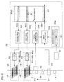
- FIG. 4 a functional block diagram of a printer head control substrate and peripheral devices
- FIG. 5 explanatory views of the printer head
- FIGS. 6 to 10 functional block diagrams each showing an outline of print processing with respect to tablets performed by the tablet printing apparatus.
- FIG. 11 is a functional block diagram showing an outline of print processing with respect to tablets performed by a tablet printing apparatus according to another embodiment.
- the tablet printing apparatus is an apparatus that carries out single-color or polychromic printing with respect to tablets. Specifically, it is an apparatus that discharges one or more types of color inks onto tablets by using an inkjet printer to form color dots on tablet surfaces, thereby providing multiple colors (including color printing).
- the single-color printing in this specification means printing effected in one color
- the polychromic printing means printing in two or more colors including color printing.
- a tablet printing apparatus 1 includes a housing 3, supplying means 10 that is provided in the housing 3 to supply tablets T, tablet conveying means 20 that is arranged to be continuous with the supplying means 10 and has a conveying path, position detecting means (an encoder 28, a tablet sensor 29), printing means 40 for performing printing by discharging inks to the tablets T conveyed by the tablet conveying means 20, printing controlling means 30 (a control computer 31, a unit control substrate 32, and others), and examining means 50 arranged on a downstream side of the conveying path of the tablet conveying means 20 as main constituent elements.
- position detecting means an encoder 28, a tablet sensor 29
- printing means 40 for performing printing by discharging inks to the tablets T conveyed by the tablet conveying means
- printing controlling means 30 a control computer 31, a unit control substrate 32, and others
- examining means 50 arranged on a downstream side of the conveying path of the tablet conveying means 20 as main constituent elements.
- the housing 3 is a square box type member that accommodates various kinds of devices such as a supply hopper 11, and an upper space partitioned by an intermediate plate 3a, a side plate 3b, and a top panel 3c is formed. It is to be noted that dotted lines indicate the side plate 3b and the top panel 3c to visualize various kinds of devices arranged in the upper space for facilitating the understanding of the invention.
- a circular opening 3d is formed in the top panel 3c on one end side in a longitudinal direction.
- the supplying means 10 is provided under the opening 3d in the upper space of the housing 3.
- the supplying means 10 includes the supply hopper 11, a vibrating feeder 12 that is arranged below the supply hopper 11 and has a discharge opening, and a rectifying turntable 13 arranged below the discharge opening of the vibrating feeder 12.
- the supply hopper 11 is a device that supplies the tablets T to the vibrating feeder 12, and it is formed of a funnel-shaped member that has a slot at an upper part and has a lower part with a reduced diameter.
- the supply hopper 11 is positioned in the upper space in such a manner that the slot coincides with the opening 3d of the top panel 3c, and each tablet T is put into the supply hopper 11 through the opening 3d of the top panel 3c.
- the vibrating feeder 12 is a device that feeds the tablet T supplied from the supply hopper 11 to the rectifying turntable 13.
- the vibrating feeder 12 in this embodiment has a non-illustrated electromagnetic oscillator therein, and it can convey the tablet T by using oscillation energy generated by the electromagnetic oscillator.
- the vibrating feeder 12 is formed of a horizontal portion that is placed on the supply hopper 11 side and horizontally arranged and an inclined portion that is placed on the rectifying turntable 13 side and has an end side obliquely inclined toward the lower side. On an end face of this inclined portion, a discharge opening from which the tablets T conveyed from the supply hopper 11 are dropped onto the rectifying turntable 13 is formed.
- the rectifying turntable 13 is a device that brings the tablets T dropped from the vibrating feeder 12 into line and transfers them to the tablet conveying means 20.
- a rotatably provided discoid rotator, a peripheral wall vertically erected toward the upper side so as to surround an entire peripheral portion of the rotator, and a conveying path formed toward the tablet conveying means 20 from a part of the peripheral wall are provided on an upper surface of the rectifying turntable 13.
- the tablets T that have dropped onto the upper surface of the rectifying turntable 13 roll and move to the outer periphery with the rotation of the rotator, and they align along the peripheral wall. Some of the tablets T that move along the peripheral wall are transferred to a conveying belt 24 of the tablet conveying means 20 through a conveying path provided on the peripheral wall.
- the tablet conveying means 20 has a case body 21, the conveying belt 24 that revolves and moves on and in the case body 21, a motor 25 (not shown in FIG. 1 ) as driving means for rotating and driving the conveying belt 24, a plurality of pulleys 26 wound around the conveying belt 24, and a suction pump 27 (not shown in FIG. 1 ) as negative pressure means for forming a negative pressure in the case body 21 as main constituent elements.
- FIG. 3 is a vertical cross-sectional view of the tablet conveying means 20 and shows a state from a direction of a line B-B in FIG. 2 .
- the case body 21 is formed of a square box body having an opened upper surface, and an accommodating space is formed in this case body.
- a pair of left and right slit plates 22a and 22b are arranged in the opening of the case body 21 along the longitudinal direction of the case body 21.
- Each of the slit plates 22a and 22b is a member formed of a material such as aluminum.
- the slit plates 22a and 22b are fixed to the case body 21 in a state where they face each other in the horizontal direction, and a slit 20a serving as an inlet opening is formed between upper edges of the slit plates 22a and 22b. Respective opposite surfaces of the slit plates 22a and 22b protrude toward the other sides on the upper side, and a lateral width of the slit 20a is narrowed in this protruding region. Upper surfaces of the slit plates 22a and 22b are subjected to, e.g., TUFRAM (registered trademark) processing, whereby skidding between these surfaces and the conveying belt 24 is smooth.
- TUFRAM registered trademark
- the conveying belt 24 is a member that conveys the tablets T, and it is configured as an endless belt that circulates on and in the case body 21 along the longitudinal direction of this body.
- the conveying belt 24 according to this embodiment has a configuration that two belts 24a and 24b are arranged in parallel and the slit 20a is formed between these belts. Further, each of the belts 24a and 24b in this embodiment is a timing belt having convex teeth formed on one surface thereof.
- a material of the conveying belt 24 one that has appropriate elasticity and can adsorb and hold the tablets T can suffice, and rubber or plastic is used, for example.
- the conveying belt 24 forms a conveying path on the upper surfaces of the slit plates 22a and 22b along the longitudinal direction.
- the conveying belt 24 is wound around an output shaft of the motor 25 and the plurality of pulleys 26 and can revolve and move based on the swiveling motion of the motor 25.
- a gear is disposed to the output shaft of the motor 25, and both the belts 24a and 24b are wound around this gear to form a state that convex teeth of the belts 24a and 24b and the gear mesh with each other.
- each of the plurality of pulleys 26 is formed of a timing pulley having concave portions formed to mesh with the convex teeth of the belts 24a and 24b, and both the belts 24a and 24b are wound around these pulleys 26 so that the convex teeth of the belts 24a and 24b mesh with the concave portions of the pulleys 26.
- the belts 24a and 24b mesh with the pulleys 26 in this manner, slip does not occur between the belts 24a and 24b and the pulley 26 even if the conveying belt 24 is moved at a high speed. Therefore, the belts 24a and 24b can be moved at a high speed, thereby conveying the tablets T at a high speed. Furthermore, both the belts 24a and 26b mesh with the same pulleys 26, and hence the two belts 24a and 24b can revolve and move while synchronizing their speeds with each other. Accordingly, a difference in speed between the belts 24a and 24b is not produced, and displacement of the tablets T hardly occurs.
- Protruding portions that protrude toward the lower side along the longitudinal direction are formed on the lower surfaces of the belts 24a and 24b.
- concave grooves in which the protruding portions of the belts 24a and 24b are fitted are formed on the upper surfaces of the slit plates 22a and 22b.
- the belt 24a revolves and moves along the concave groove in a state that the protruding portions are fitted in the concave groove of the slit plate 22a.
- the belt 24b revolves and moves while being fitted in the concave groove of the slit plate 22b. Since the protruding portions of the belts 24a and 24b are fitted in the concave grooves of the slit plates 22a and 22b in this manner, the conveying belt 24 can be prevented from deviating in the lateral direction or coming off.
- a hollow protruding portion 21a protruding toward the lower side is formed on the lower surface of the case body 21, and this protruding portion 21a is connected with the suction pump 27.
- the suction pump 27 is a device that sucks air in the case body 21 to form a negative pressure in the case body 21.
- the suction pump 27 is arranged in a lower space partitioned by the intermediate plate 3a (see FIG. 1 ) of the housing 3, and the protruding portion 21a of the case body 21 communicates with lower space through this intermediate plate 3a.
- the inside of the case body 21 communicates with the outside through the slit 20a alone, and the airtightness is assured for any other portions. Therefore, when the suction pump 27 forms a negative pressure in the case body 21, outside air is sucked into the case body 21 through the slit 20a.
- the tablet T mounted on the upper surface of the conveying belt 24 in contact with the belts 24a and 24b is held and fixed in a state that they are adsorbed onto the upper surfaces of the belts 24a and 24b by suction of this outside air. In this state, the tablet T is conveyed toward a moving direction A1-A2 based on the swiveling motion of the conveying belt 24.
- the tablet conveying means 20 conveys the tablet T in the state that it is absorbed onto the conveying belt 24 as explained above, the tablet T hardly comes off even if the conveying belt 24 is moved at a high speed, thereby conveying the tablet T at a high speed.
- the absorption in the present invention includes fixing the tablet T by using the suction force.
- the tablet conveying means 20 is not restricted to one that adsorbs the tablet T onto the conveying belt 24 by suction using the pump like the embodiment, and the suction force (e.g., magnetic force or static electricity) may be generated by any other means to adsorb and hold the tablet T.
- the tablet conveying means 20 is not restricted to such means using the suction force, and the conveying belt 24 having an adhesive layer formed on a surface thereof may be used to adsorb the tablet T onto the surface of the conveying belt 24.
- the tablets T transferred from the rectifying turntable 13 can be sequentially adsorbed at irregular positions along the moving direction A1-A2 of the conveying belt 24 and conveyed every time they are transferred from the rectifying turntable 13 without aligning the tablets T at predetermined intervals. Therefore, the tablets T do not have to be aligned on the conveying belt 24 at predetermined intervals, and a wait time when transferring the tablets T from the rectifying turntable 13 to the conveying belt 24 is hardly produced. Accordingly, the tablets T transferred from the rectifying turntable 13 can be immediately conveyed, thereby reducing a tablet conveying time.
- the tablets T are adsorbed onto the conveying belt 24, the tablets T are hardly displaced or come off even if the conveying belt 24 is moved at a high speed. Therefore, a rotating speed of the conveying belt 24 can be increased to move the tablets T at a high speed.
- the conveying belt can move at a speed falling within the range of 500 mm/second to 2000 mm/second, the tablets T are conveyed at a moving speed of 1000 mm/second or above.
- later-described position detecting means detects a moving state or a moving position of each tablet T, and printing controlling means adjusts printing onto each tablet, thereby enabling printing at an accurate position with respect to the tablet T.
- the encoder 28 is means which is disposed to one of the pulleys 26 and detects a rotating position of the pulley 26.
- the encoder 28 detects a rotating position or/and a rotating state of the pulley 26 in this manner to acquire a moving position or/and a moving state of the conveying belt 24 wound around the pulleys 26.
- a moving state or/and a moving position of each tablet T can be indirectly acquired.
- the encoder 28 a known rotary encoder can be used. As a type of the rotary encoder, an absolute type or an incremental type can be adopted. Further, the means for detecting a position of each tablet T is not restricted to the above-described encoder 28, any other means for magnetizing the conveying belt at predetermined intervals and detecting a moving position or/and a moving state of the conveying belt by using a magnetic sensor may be used, for example.
- the tablet sensor 29 is means that is provided above the conveying belt 24 on an upstream side and detects each tablet T conveyed on the conveying belt 24. Furthermore, as the tablet sensor 29, for example, an infrared sensor adopting a scheme that an infrared ray is emitted toward the slit 20a of the conveying belt 24 and the infrared ray is blocked when the tablet T passes can be used. When the tablet T is detected, the tablet sensor 29 outputs a tablet detection signal. It is to be noted that, as the tablet sensor 29, one using any other optical detecting means or means other than the optical means, e.g., a nearby sensor that detects a change in electrostatic capacitance can be used.
- the encoder 28 and the tablet sensor 29 can acquire a moving position of each tablet T conveyed by the conveying belt 24. That is, the tablet sensor 29 detects that the tablet T has passed a predetermined position, and the encoder 28 counts an output pulse signal, thereby measuring a moving position of the conveying belt 24.
- the pulse signal output from the encoder 28 is, e.g., a pulse number output during elapse of 10 ⁇ s, and a signal in units of 10 ns obtained by integrating a wavelength per pulse number with respect to the output pulse number can be used.
- a later-described ink discharge signal can be configured to be output in synchronization with the pulse signal output from this encoder 28.
- the output pulse signal of the encoder 28 is matched with a print resolution in advance.
- the print resolution, a conveying speed of the tablet T, and an ink discharge frequency (Hz) have a close relationship
- the ink discharge frequency is a moving distance in units of millimeter/an interline distance in units of print resolution per second.
- the encoder 28 and the tablet sensor 29 are means that acquire a moving position and a moving state of the tablet T in cooperation with each other, and both these members constitute the position detecting means in the present invention.
- the printing controlling means 30 is formed of the control computer 31, the unit control substrate 32, and others.
- the control computer 31 includes a central processing unit (a CPU), a storage device (e.g., an HDD, an ROM, or an RAM), an input/output interface, and others, and the control computer 31 and the later-described unit control substrate 32 constitute the printing controlling means according to the present invention.
- This control computer 31 performs the management of the entire apparatus, e.g., ON/OFF of a power supply of the entire apparatus, various kinds of settings or changes in the entire apparatus, display of a state of the entire apparatus, and others.
- appropriate settings can be formed in accordance with a shape or a size of the tablet T as a printing target, a processing speed for the tablet T by the tablet printing apparatus 1, an installation environment of the tablet printing apparatus 1, and others.
- a distance between a nozzle hole 43a and the tablet T is approximately 2 mm
- a bore diameter of the nozzle hole 43a is approximately 20 ⁇ m
- an ink discharge amount (per droplet) is approximately 11 picoliters
- a distance from the tablet sensor 29 to a printer head 43 is approximately 120 mm
- a distance from the printer head 43 to a printer head 47 is approximately 850 mm.
- a print image of the tablet T can be directly created by an operator, or a print image created by an external device can be input.
- the print image is data that is created in a format such as bitmap or JPEG and has pixels represented by three primary colors of light including RGB (red, green, and blue) as constituent units.
- the created or input print image is stored in the control computer 31.
- the control computer 31 is electrically connected with the unit control substrate 32 and outputs a stored print image to the unit control substrate 32.
- the unit control substrate 32 is a substrate that controls inkjet printers 42 and 46, and it is electrically connected with respective printer head control substrates 44 and 48 of the inkjet printer 42 and the inkjet printer 46 through buses to input/output a control signal or image data. Further, the unit control substrate 32 is also connected with the encoder 28 and the tablet sensor 29, and it processes and outputs a print image based on a pulse signal supplied from the encoder 28 or a tablet detection signal fed from the tablet sensor 29.
- the unit control substrate 32 has an image data memory 32a that stores an image to be printed on the tablet T in a master image M, a timing generation controller 32b that generates a timing signal based on a signal from the encoder 28, a buffer memory 32c that temporarily stores the master image M of the image data memory 32a, a write controller 32d that controls writing the master image M into the buffer memory 32c based on a tablet detection signal from the tablet sensor 29 and a timing signal from the timing generation controller 32b, a first read controller 32e that controls reading the master image M from the buffer memory 32c, and a second read controller 32f that controls reading the master image M from the buffer memory 32c as main constituent elements.
- the image data memory 32a is means for storing an image to be printed onto the tablet T as the master image M.
- the master image M is image data having a format such as bitmap created by the control computer 31 and includes in a column direction a plurality of pieces of row data (line data) each associated with an image (a raster image) corresponding to one line along the moving direction A1-A2 of the tablets T.
- the timing generation controller 32b is means for controlling transfer of an address of line data stored in the buffer memory 32c and writing of line data into the buffer memory 32c by the controller 32d in synchronization with a pulse signal from the encoder 28.
- the timing generation controller 32b generates a latch signal as a timing signal every time it receives a pulse signal cyclically output from the encoder 28, and transmits it to the buffer memory 32c and the write controller 32d.
- the buffer memory 32c is means for temporarily storing the master image M stored in the image data memory 32a in accordance with each line data.
- the buffer memory 32c according to this embodiment is formed of an FIFO type ring buffer. That is, the buffer memory 32c is a fixed-length buffer having a start address ST and an end address END and has a configuration that an address following the end address END coincides with the start address ST.
- the buffer memory 32c has at least a capacity that can store a line number obtained by dividing a physical distance from a position immediately below the tablet sensor 29 to a position immediately below the printer head 47 (i.e., a printing point) by a printing unit of the line head. Moreover, the buffer memory 32c includes a pointer control circuit (not shown), and a pointer specified by this pointer control circuit specifies a write address and a read address for data in a memory array.
- a first read address RD1 and a second read address RD2 are provided in the buffer memory 32c.
- the first read address RD1 is associated with a position immediately below the printer head 43 of the inkjet printer 42. Additionally, the number of lines that can be stored in a space between the start address ST and the first read address RD1 coincides with the number obtained by dividing a physical distance from a position immediately below the tablet sensor 29 to a position immediately below the printer head 43 by a printing unit of the line head.
- the second read address RD2 is placed on the end address END side apart from the first read address RD1.
- the second read address RD2 is associated with a position immediately below the printer head 47 of the inkjet printer 46. Further, the number of lines that can be stored in a space between the first read address RD1 and the second read address RD2 coincides with the number obtained by dividing a physical distance from the position immediately below the printer head 43 to the position immediately below the printer head 47 by the printing unit of the line head.
- the write controller 32d is means for reading line data from the image data memory 32a and writing it into the buffer memory 32c based on a tablet detection signal from the tablet sensor 29.
- the write controller 32d receives the tablet detection signal from the tablet sensor 29, it reads out line data corresponding to one line from the master image M of the image data memory 32a at a timing of receiving a latch signal from the timing generation controller 32b and writes it at the start address ST of the buffer memory 32c.
- the pointer control circuit of the buffer memory 32c receives the latch signal from the timing generation controller 32b, instructs the buffer memory 32c to move a pointer, and shifts the address at which the master image M is stored in the buffer memory 32c toward the end address END side in increments of predetermined bits.
- the buffer memory 32c sequentially stores line data read from the image data memory 32a in the column direction in synchronization with the rotation of the encoder 28, and shifts already stored line data toward the end address END.
- the first read controller 32e is means for reading out image data stored at the read address RD1 of the buffer memory 32c and outputting it to the printer heads 43 via the printer head control substrate 44.
- the first read controller 32e reads out the master image M from the buffer memory 32c.
- the read master image M is output to the printer head control substrate 44 of the inkjet printer 42.
- the second read controller 32f is means for reading image data stored at the read address RD2 of the buffer memory 32c and outputting it to the printer heads 47 through the printer head control substrate 48.
- the second read controller 32f reads the master image M from the buffer memory 32c.
- the read master image M is output to the printer head control substrate 48 of the inkjet printer 46.
- the inkjet printers 42 and 46 will now be described.
- the inkjet printer 42 according to this embodiment is a printer unit that discharges yellow/magenta inks onto the tablet T to print yellow/magenta images.
- the inkjet printer 46 is a printer unit that discharges cyan/black inks onto the tablet T to print cyan/black images.
- the inkjet printer 42 includes the plurality of printer heads 43 that discharge the ink toward the tablets T, the printer head control substrate 44 that controls these printer heads 43, and a sub-tank 45 that stores the ink.
- An ink tank 41 that stores yellow, magenta, cyan, and black inks is arranged above the inkjet printers 42 and 46.
- Printing means 40 according to this embodiment adopts a line head scheme that the printing means 40 is fixed in a state that the plurality of printer heads 43 are arranged at predetermined positions above the conveying belt 24 in parallel and the tablets T themselves as printing targets move.
- the printer head 43 is a device that discharges droplets of the ink toward each tablet T.
- Each printer head 43 includes an ink chamber that accommodates the ink, nozzle holes communicating with the outside from the ink chamber, a piezo element (a piezo actuator) as an actuator that applies a pressure to the ink in the ink chamber to be discharged from the nozzle holes, and an electrode that applies a voltage for transforming the piezo element as main constituent elements (all the elements are not shown).
- the ink chamber communicates with the sub-tank 45, and it is filled with the ink accommodated in the sub-tank 45.
- the sub-tank 45 communicates with the ink-tank 41, and it can accommodate a yellow ink and a magenta ink stored in the ink tank 41, respectively.
- the nozzle holes are formed at a lower part of the ink chamber so that the ink filling the ink chamber can be discharged toward the outside.
- the piezo element is arranged on an opposite side of the nozzle holes in the ink chamber.
- the piezo element is configured to be sandwiched between a pair of electrodes, and it has properties of transforming in response to a voltage applied from a non-illustrated power supply connected with this electrodes.
- a volume in the ink chamber varies, and a part of the ink in the ink chamber is discharged through the nozzle holes.
- a piezo thin film formed by controlling polarizing directions is used.
- the piezo thin film is a thin film that is formed of, e.g., a lead zirconate titanate (Pb(Zr x ,Ti 1-x )O 3 ) and has a film thickness of approximately 2 to 5 ⁇ m, and it is formed by a technique such as sputtering.
- This piezo thin film element has a configuration that polarizing directions are aligned in one direction as compared with a general sintered body piezo element produced by sintering a material.
- the piezo thin film has a high electric field intensity and high piezoelectric properties, and its electromechanical conversion efficiency or intensity is approximately double a counterpart of the sintered body piezo element. Therefore, the number of nozzle holes per unit area is highly integrated to be double a counterpart of the conventional sintered body piezo element.
- FIG. 5(a) is a perspective view showing the printer heads 43 from an obliquely upper side. As shown in this drawing, the plurality of printer heads 43 are arranged in parallel in this embodiment. Further, each printer head 43 is arranged to be inclined in an oblique direction with respect to the moving direction A1-A2 of the tablets T.
- FIG. 5(b) is a bottom view showing the printer heads 43 from the lower side in a state where the nozzle holes are seen from the front side. As depicted in this drawing, a plurality of circular nozzle holes 43a are provided in the printer heads 43, and the ink is discharged toward the tablets T from these nozzle holes 43a.
- each printer head 43 two nozzle hole columns are formed along the longitudinal direction, and the respective nozzle hole columns are separated on left and right sides at a central portion of the printer head 43.
- the left and right nozzle hole columns are formed as a nozzle hole column group 43b (43b-1, 43b-2) and a nozzle hole column group 43c (43c-1, 43c-2), respectively.
- two columns on one end side in the longitudinal direction of the printer head 43 correspond to yellow nozzle hole columns 43b-1 and 43b-2, and two columns on the other end side of the same correspond to magenta nozzle hole columns 43c-1 and 43c-2.
- the printer head 43 is arranged in such a manner that an aligning direction of the nozzle holes 43a is inclined in the oblique direction with respect to the moving direction A1-A2 of the tablets T.
- an inclination angle of the aligning direction of the nozzle holes 43a with respect to the moving direction A1-A2 is approximately 5 to 60°.
- the nozzle holes 43a are arranged to be inclined with respect to the moving direction A1-A2.
- the respective nozzle holes 43a are translated to be aligned along a perpendicular direction (i.e., a width direction of the conveying belt 24) of the moving direction A1-A2, they are arranged at positions at which they are aligned at equal intervals to overlap some of the adjacent nozzle holes 43a.
- the nozzle holes 43a adjacent to each other are aligned at equal intervals in a state that they partially overlap each other when projection is carried out along the perpendicular direction of the moving direction A1-A2.
- the nozzle holes are likewise aligned at equal intervals.
- the nozzle holes 43a adjacent to each other are arranged at equal intervals so as to partially overlap.
- each printer head 43 is inclined with respect to the perpendicular direction (the width direction of the conveying belt 24) of the moving direction A1-A2, the number of the nozzle holes 43a per unit length in the width direction of the conveying belt 24 increases, thereby highly integrating the nozzle holes 43a. Therefore, a resolution of identifying information printed on the tablets T can be improved. It is to be noted that the nozzle holes 43a in the magenta nozzle hole columns 43c-1 and 43c-2 are arranged in the same manner.
- the printer head control substrate 44 is means for collectively controlling the plurality of printer heads 43 arranged in parallel. That is, the printer head control substrate 44 receives print data (line data) from the unit control substrate 32, drives and controls the plurality of printer heads 43 based on this line data to perform printing on the tablets T.
- the printer head control substrate 44 includes a storage section 44a that stores the line data supplied from the unit control substrate 32, a color converting section 44b that coverts RBG information for each pixel in the line data into color information of CMYK (cyan, magenta, yellow, and black), and a head output section 44c that drives the printer heads 43 based on the color information from the color converting section.
- CMYK cyan, magenta, yellow, and black
- the storage section 44a is formed of a memory such as an RAM, and it temporarily stores the line data (RGB information) supplied from the unit control substrate 32.
- the color converting section 44b is formed of an arithmetic device such as a DSP, and it reads out the line data stored in the storage section 44a and converts it into color information of CMYK.
- the line data fed from the unit control substrate 32 is constituted of 256-gradation data of RGB, and the color converting section 44b converts this RGB data into 256-gradation data of CMYK.
- the color-converted line data is supplied to the head output section 44c.
- the head output section 44c receives and sorts the line data and drives and controls the printer heads 43 based on data of yellow (Y) and magenta (M) alone in CMYK. Giving a more detailed explanation, the head output section 44c receives the CMYK color information and executes processing of sorting the color information of yellow (Y) and magenta (M) in a discharge order. In this sorting, the data is sorted and stored in a memory such as a non-illustrated RAM of the head output section 44c in such a manner that the data is output in an ink discharge order of the ink holes 43a of the printer heads 43.
- the ink discharge order is an order that the tablets T are conveyed along the moving direction of the tablets T.
- this order is an order from the left-hand side (an upstream side) to the right-hand side (a downstream side).
- the head output section 44c outputs the data of yellow and magenta in the color information of CMYK to the printer heads 43.
- each printer head 43 drives the piezo elements at positions associated with the respective ink holes 43a so as to discharge the yellow ink from the nozzle holes 43a of the yellow nozzle hole columns 43b-1 and 43b-2 and discharge the magenta ink from the nozzle holes 43a of the magenta nozzle hole columns 43c-1 and 43c-2.
- the inkjet printer 46 has the similar configuration. That is, the inkjet printer 46 includes the printer heads 47, the printer head control substrate 48, and a sub-tank 49 as main constituent elements.
- the sub-tank 49 communicates with the ink tank 41 and can accommodate the cyan ink and the black ink stored in the ink tank 41. It is to be noted that these constituent elements except the printer head control substrate 48 are the same as those described in relation to the inkjet printer 42, thereby omitting a detailed explanation thereof.
- the printer head control substrate 48 includes a storage section 48a that stores line data supplied from the unit control substrate 32, a color converting section 48b that converts RGB information for each pixel of the line data into color information of CMYK, and a head output section 48c that drives the printer heads 47 based on the color information from the color converting section.
- the color converting section 48b reads the line data stored in the storage section 48a and converts it into color information of CMYK.
- the head output section 48c drives and controls the printer heads 47 based on data of cyan (C) and black (K) alone in CMYK as different from the head output section 44c.
- Each printer head 47 discharges the cyan ink and the black ink toward each tablet T based on a control signal from the head output section 48c.
- images of cyan and black are printed on each tablet T.
- the examining means 50 includes a printing section examination unit 51 and a quality judgment unit 52 provided to be adjacent to the printing section examination unit 51.
- the printing section examination unit 51 is means for detecting identifying information printed on a printed surface of the tablet T.
- the printing section examination unit 51 includes, e.g., a CCD color camera, shoots each tablet T, and transmits acquired data to the quality judgment unit 52.
- the quality judgment unit 52 is means for judging whether printing on each tablet T is good.
- the quality judgment unit 52 stores a good printing pattern in the storage device in advance and compares imaging data of each tablet T supplied from the printing section examination unit 51 with the good printing pattern to judge whether a predetermined image has been printed on the tablet T. When it is determined that the predetermined pattern has not been printed on the tablet T as a result of the judgment, the tablet T is collected as a defective product through a route different from that for a group of other good products.
- the tablet as a printing target of the tablet printing apparatus will now be described.
- a type of the tablet subjected to printing by the tablet printing apparatus is not restricted in particular, printing can be effected with respect to a core tablet (a plain tablet) obtained by just carrying out shape forming of a raw material including active substances without surface coating or a coating tablet obtained by coating a surface of a core tablet with saccharose or a water-soluble polymer.
- a tablet shape forming method there is, e.g., a compression forming method for tableting a raw material to form a shape or a non-compression forming method for drying in a mold a raw material subjected to wet kneading without tableting. Since the tablet printing apparatus 1 according to this embodiment can perform printing in a non-contact manner, it can be preferably used with respect a core tablet that is difficult to be subjected to clear printing in regular offset printing since a powder adheres to a surface.
- an orally-disintegrating tablet As a type of the core tablet, there is, e.g., an orally-disintegrating tablet. Since the orally-disintegrating tablet is a medicinal substance that orally solves in saliva to turn to a liquid medication and can be taken without water, it is characterized in that even aged persons or children who have difficulty in swallowing can easily take such a tablet or taking such a tablet is easy even in an environment that water is difficult to obtain.
- the orally-disintegrating tablet can be roughly divided into a template tablet produced by non-compression forming, a molded tablet formed by performing tableting under a very low pressure, and a compressed tablet formed by performing tableting under a relatively high tableting pressure.
- the template tablet can be produced by precisely filling a casting mold with chemicals, sugars, binders, and others and removing moisture by freeze drying or low-temperature draught drying.
- a specific example of such a template tablet there is "Zydis” (a product name: Zofran (a registered trademark) Zydis (a registered trademark)).
- the molded tablet is a tablet that can be produced by tableting while maintaining porosity equivalent to that of the template tablet, and it is produced by, e.g., moistening a mixture of chemicals, sugars, and a binder with a mixed liquid of a small amount of water and alcohol and molding this moist mixture under a very low pressure to be dried. Further, as the molded tablet, it is possible to adopt a tablet that is produced by, e.g., a tableting machine incorporating a pressurized weight filling mechanism and a polymeric film intervening forming mechanism for avoiding attachment.
- the compressed tablet is produced by tableting chemicals, a binder, and others by a general tabling facility. Since the compressed tablet is formed under a tableting pressure higher than that for the template tablet or the molded tablet, it has high hardness and a low void ratio as compared with these tablets. It is to be noted that the compressed tablet may contain sugar for maintaining high porosity or an additive having a disintegrating function.
- the compressed tablet can be manufactured by granulating sugar having low formability by using sugar having high formability and compressing and forming the granulated sugar.
- Such a compressed tablet is obtained by applying disintegrating properties provided by the sugar that is superior in disintegrating properties but has low formability and physical characteristics with different tablet formability provided by the sugar that is inferior in disintegrating properties but has high formability, and it has predetermined strength and characteristics of rapid disintegration in the oral cavity.
- sugar having low formability there is sugar selected from, e.g., lactose, mannitol, glucose, saccharose, xylitol, and others.
- sugar having high formability there is sugar selected from maltose, maltitol, sorbitol, lacose and fructose, and others.
- the compressed tablet can be also obtained by performing compression forming with sugar (A) and amorphous sugar (B) being used as binders.
- This compressed tablet has tablet strength improved by utilizing a change in physicality due to transition from an amorphous material to a crystal of the sugar.
- the sugar (A) is sugar or sugar alcohol that can solve in the oral cavity, and there are, e.g., lactose, glucose, trehalose, mannitol, erythritol, and others.
- the amorphous sugar (B) means sugar in an amorphous state or sugar that is going to be amorphous, it is obtained by dissolving crystalline sugar that is going to be amorphous in a solvent such as water or alcohol, removing the solvent from this dissolved liquid, and effecting drying.
- An additive amount of the amorphous sugar (B) is approximately 2 to 20 weight% with respect to the sugar (A).
- the compressed tablet may be a compressed tablet obtained by performing compression forming with respect to a microcapsulated chemical and a foam disintegrating agent that foams with moisture (an organic acid and a carbonate) together with a diluting agent.
- the organic acid at least one acid is preferably selected from a group including a citric acid, a tartaric acid, a malic acid, a fumaric acid, an adipic acid, a succinic acid, an acid anhydride obtained from these acids and salt, and mixtures of these materials.
- the tablet disintegration of this compressed tablet advances when the foam disintegrating agent foams due to permeation of saliva in the mouth to help disintegration of the tablet and saliva production is facilitated by stimulation of the foam.
- the compressed tablet may be a tablet that contains active substances as fine crystals or fine particles and that can be obtained by mixing the effective substances with a disintegrating agent and an expansive agent to be subjected to compression forming.
- active substances as fine crystals or fine particles and that can be obtained by mixing the effective substances with a disintegrating agent and an expansive agent to be subjected to compression forming.
- a disintegrating agent for example, carboxymethyl cellulose, reticular polyvinyl pyrrolidone, and others as the disintegrating agent, and there are microcrystalline cellulose, starch, modified starch, and others as the expansive agent.
- the compressed tablet may be a tablet obtained by performing compression forming by using a special tableting machine.
- a tablet there is, e.g., a tablet obtained by spraying a lubricant onto surfaces of a mortar and a pestle to be diffused by a high-tension pulse air generation apparatus and effecting external lubricant tableting. Since the lubricant can be uniformly diffused with respect to desired regions of the mortal and the pestle by using the high-tension pulse air, an additive amount can be reduced to at least 1/10 of a regular amount as compared with the conventional method, and a quality of the tablet can be also improved.
- the core tablet it is possible to adopt not only a circular shape seen in a planar view but also any shapes such as an elliptic shape, a long elliptic shape, a triangular shape, a square shape, or a polygonal shape as long as it is a shape that can be conveyed by the tablet conveying means 20.
- the ink is apt to permeate pores of the tablet as the void ratio is high, and a powder amount on the surface is also increased, whereby bleeding or detachment of the ink readily occurs. Therefore, it is preferable for the void ratio to fall within the range of 5% to 40%, more preferably the range of 5% to 35%, or the range of 5% to 30% as another preferred conformation. When the void ratio is in this range, bleeding or detachment of the printed ink hardly occurs, and the identifying information can be clearly printed on the surface of the tablet.
- active substances contained in the tablet are not restricted in particular, and substances configured to have desired components can be determined as the active substances depending on medical benefits of each tablet.
- active substances contained in the tablet there are famotidine, tamsulosin hydrochloride, and others.
- the tablet printing apparatus can be preferably used with respect to the tablets, but it can be also used with respect to other solid medicines such as capsules or trochiscis besides the tablet. Additionally, it can be also used with respect to sweets such as a lemon soda or block sugar and food items. That is, printing can be basically performed with respect to small goods including the tablet as long as they can be conveyed by the conveying device and on which the identifying information can be printed.
- an edible ink that is safe even if ingested by persons is preferable.
- Thee edible ink is a constituent mainly including an edible dye, a water-soluble solvent, and purified water.
- an edible dye a dye that is in a specified additive list in artificial colors determined by a food hygiene law is preferable.
- identifying information printed on the surface of the tablet there are characters, figures, photographic images, and others.
- a product name of a medical agent, a titer, a pharmaceutical manufacturer name, a pharmaceutical manufacturer logo, and others can be printed.
- the tablet production method includes a tablet forming step S1, a tablet conveying step S2, a position detecting step S3, a printing controlling step S4, and a printing step S5.
- a tablet forming step S1 a raw material containing active substances is utilized to form tablets based on compression forming by a known technology.
- the tablet conveying step S2 is executed.
- this tablet conveying step S2 as shown in FIG.
- the tablets T are first supplied to the supply hopper 11 and then fed to the rectifying turntable 13 by vibration energy of the vibrating feeder 12.
- the tablets T supplied to the rectifying turntable 13 are sequentially pushed out onto the conveying belt 24 of the tablet conveying means 20 in a state that they are aligned in line by the rotator.
- the tablets T pushed out and mounted on the conveying belt 24 are held and fixed on the conveying belt 24 by the suction pump 27 and conveyed in the moving direction A1-A2 at a high speed. Then, the position detecting step S3 is carried out.
- the tablet sensor 29 is provided in the middle of the conveying path of the tablet conveying means 20, the tablets T conveyed immediately below the tablet sensor 29 are detected by the tablet sensor 29, and a tablet detection signal is generated.
- the tablet detection signal is input to the write controller 32d of the unit control substrate 32.
- a predetermined number of pulse signals are output per rotation from the encoder 28 coupled with the pulley 26 while the conveying belt 24 rotates.
- the pulse signals are input to the timing generation controller 32b of the inkjet printer 42 through the unit control substrate 32. Then, the printing controlling step S4 is effected.
- the timing generation controller 32b generates a latch signal synchronized with each pulse signal to be output to the write controller 32d and the buffer memory 32c.
- the write controller 32d receives the tablet detection signal from the tablet sensor 29, then reads line data corresponding to one line of the master image M from the image data memory 32a at a timing of receiving the latch signal from the timing generation controller 32b for the first time, and writes the read data at the start address ST in the buffer memory 32c.
- the timing generation controller 32b shifts an address storing the master image M stored in the buffer memory 32c toward the end address END for predetermined bits every time the pulse signal is received.
- the write controller 32d sequentially reads the line data of the master image M stored in the image data memory 32a for each line in the columnar direction in synchronization with this address shift, and writes the read data at the start address ST in the buffer memory 32c.
- the master image M is sequentially written into the buffer memory 32c in accordance with each line.
- the line data in the first line of the master image M reaches the first read address RD1.
- the first read address RD1 in the buffer memory 32c is a position corresponding to a place immediately below the printer head 43.
- the first read controller 32e reads the line data of the master image M stored at the first read address RD1 and outputs it to the printer head control substrate 44 of the inkjet printer 42.
- the printing step S5 is effected.
- the line data is temporarily stored in the storage section 44a, this data is converted into color information of CMYK by the color converting section 44b, then, the head output section 44c outputs yellow and magenta information to the printer heads 43, and ink discharge control is effected.
- the printer heads 43 discharge the yellow ink and the magenta ink toward the tablets T based on the yellow and magenta information supplied from the head output section 44c. As a result, images of yellow and magenta in the line data are printed on the surface of each tablet T.
- the address shift of the master image M and the reading of the line data from the first read address RD1 are executed every time the pulse signal is output from the encoder 28, and the tablets T conveyed immediately below the printer heads 43 are sequentially subjected to printing.
- the tablets T finish passing the printer heads 43, images of yellow and magenta in images of the master image M are finally printed onto the surface of each tablet T.
- the line data stored in the buffer memory 32c is thereby subjected to the address shift and reaches the second read address RD2 as depicted in FIG. 10 .
- the second read controller 32f reads the line data stored at the second read address RD2 and outputs it to the printer head control substrate 48 of the inkjet printer 46.
- the line data of the master image M is temporarily stored in the storage section 48a and converted into color information of CMYK in the color converting section 48b, then the head output section 48c outputs cyan and black information to the printer heads 47, and ink discharge control is carried out.
- the printer heads 47 discharge the cyan ink and the black ink toward the tablets T based on cyan and black information supplied from the head output section 48c.
- images of cyan and black in the line data are printed onto the surface of each tablet T.
- the master image M stored in the buffer memory 32c is subjected to the address shift in synchronization with the pulse signal from the encoder 28, and the data is erased when the master image M reaches the end address END.
- the yellow/magenta inks are discharged, and the yellow/magenta master image M is printed.
- the cyan/black inks are discharged at a timing further delayed from the discharge timing in the inkjet printer 42.
- cyan/black images are printed onto the yellow/magenta images printed on the surface of each tablet T on the upstream side.
- the tablet detection signal is received from the tablet sensor 29 and, at the same time, the tablets conveyed at a high speed are subjected to printing in synchronization with the number of the pulse signals received from the encoder 28 provided to the conveying belt 24. That is, since the encoder 28 detects a moving distance of the conveying belt 24, a printing timing and others can be adjusted even if the movement of the conveying belt 24 is distorted, thereby enabling accurate printing just like an image.
- Each tablet T after printing is further conveyed toward the downstream side by the conveying belt 24 and imaged by the printing section examination unit 51.
- the quality judgment unit 52 judges whether a print state of each tablet T is good based on imaging data, and the tablet T determined to have a printing defect as a result of the judgment is collected in a conveying route different from the regular route. Then, the polychromic printing with respect to each tablet T is terminated.
- Using the tablet printing apparatus 1 according to this embodiment enables printing on the tablets T at a high processing speed of 100000 pieces/hour.
- a tablet printing apparatus according to another embodiment (a second embodiment) of the present invention will now be described.
- the conveying path for the tablets T is provided in a single column in the tablet printing apparatus 1 according to the foregoing embodiment (the first embodiment)
- the tablet printing apparatus according to this embodiment is characterized in that conveying paths for the tablets T are provided in multiple columns and parallel print processing can be executed with respect to the plurality of tablets T.
- This embodiment has substantially the same configuration as that of the tablet printing apparatus 1 according to the first embodiment, but it is partially different. The different configuration alone will be described hereinafter.
- a plurality of belts 124a to 124c i.e., conveying paths
- tablet sensors 129a to 129c are arranged with respect to the belts 124a to 124c, respectively.
- the belts 124a to 124c may be configured by simply providing the tablet conveying means 20 according to the first embodiment in parallel, or they may be configured by sharing other devices such as a case body 21 or a suction pump 27 and providing the plurality of belts alone in parallel.
- an image data memory 132a stores master images M1 to M3 associated with the belts 124a to 124c.
- the write controller 132d receives tablet detection signals from the tablet sensors 129a to 129c and controls writing the master images M1 to M3 into the buffer memory 132c. For example, upon receiving the tablet detection signal from the tablet sensor 129c, the write controller 132d reads the master image M3 in the image data memory 132a for one line and writes the read image at a start address ST in the buffer memory 132c. Then, line data in the buffer memory 132c is shifted toward an end address END in synchronization with a pulse signal input from the encoder 128, and the master image M3 is read in accordance with each line to be written at the start address ST.
- any other tablet sensor e.g., the tablet sensor 129a
- write processing is executed in the following procedure.
- the write controller 132d when the write controller 132d receives the tablet detection signal, the write controller 132d reads the master image M2 associated with the tablet sensor 129a from the image data memory 132a. At the same time, the tablet sensor 129c has already detected the tablets T, and line data of the master image M3 has been read in accordance with each line.
- the write controller 132d executes an OR arithmetic operation (a logical addition operation) with respect to the line data of the simultaneously read master images M2 and M3 to be combined, thereby creating image data (a combined master image).
- This combined master image is written at the start address ST of the buffer memory 132c.
- the combined master image is subjected to address shift in response to a pulse signal from the encoder 128 like the first embodiment, read out at a second read address RD1 by the first read controller 132e, and output to the printer head control substrate 144 of the inkjet printer 142.
- the printer head control substrate 144 drives and controls the printer heads 143 to print yellow and magenta images onto each tablet T.
- the combined master image is read out from the second read address RD2 by the second read controller 132f and output to the printer head control substrate 148 of the inkjet printer 146.
- the printer head control substrate 148 drives and controls the printer heads 147 to print cyan and black images onto each tablet T.
- the buffer memory does not have to be provided in accordance with each conveying path, and the configuration of the tablet printing apparatus can be simplified. It is to be noted that the example where the conveying paths are provided in three columns has been explained in this embodiment, any other conveying paths provided in multiple columns, e.g., two columns or four columns or more can be adopted.
- the present invention is not restricted to the apparatus using four types of inks like the foregoing embodiments.
- two (e.g., yellow and cyan) in four types of colors inks alone may be used to perform printing.
- the inkjet printer 42 prints yellow/magenta images and the inkjet printer 46 prints cyan/black images in each of the foregoing embodiments
- the types of colors discharged from each printer is not restricted those in such embodiments.
- the inkjet printer 42 may discharge cyan.
- one inkjet printer performs printing using two types of color inks in each embodiment
- the present invention is not restricted to such embodiments.
- one inkjet printer may be provided for each color ink, or one inkjet printer may perform printing using three types of inks and the other inkjet printer may effect printing using the remaining one ink.
- the unit control substrate side may convert the RGB information into the color information of CMYK and output the color information to the printer head control substrate, and the printer head control substrate may carry out printing and output based on the output color information.
- the ink tank shared by the respective inkjet printers is provided to supply the inks to the respective inkjet printers in the foregoing embodiment, it is possible to adopt a cartridge scheme that a plurality of ink cartridges accommodating respective color inks are inserted into the inkjet printers to be used.
- the same tablet printing apparatus was utilized with respect to three types of core tablets having different void ratios and different forming methods to perform printing under the same conditions.
- an inkjet printer manufactured by Mastermind, MMP813BT
- a black ink was adopted, and "H A" and "0.2" were written as print characters in two lines.
- the core tablets as printing targets are the following three types.
- a Zofran (registered trademark) Zydis (registered trademark) 4 mg (Glaxo Smith Kline): approximately 93% as a void ratio: an orally-disintegrating tablet (a template tablet).
- FIGS. 13(a) to (e) show printing results.
- FIG. 13(a) shows a photograph obtained by shooting the entire tablet after printing characters on the Celecox (registered trademark) tablet
- FIG. 13(b) shows a photograph obtained by shooting the entire tablet after printing the characters on the Harnal (registered trademark) D tablet
- FIG. 13(c) shows a magnified photograph of the print characters after printing the characters on the Celecox (registered trademark) tablet
- FIG. 13(d) shows a magnified photograph of the print characters after printing the characters on the Harnal (registered trademark) D tablet
- FIG. 13(e) shows a magnified photograph of the print characters after printing the characters on the Zofran (registered trademark) Zydis (registered trademark), respectively.
- Table 1 shows results obtained by measuring a vertical line width and a lateral line width of a character "H" in the characters printed on each of the Celecox (registered trademark) tablet (Examples 1 and 2), the Harnal (registered trademark) D tablet (Examples 3 and 4), and Zofran (registered trademark) Zydis (registered trademark) (Examples 5 and 6).
- Example 1 Example 2
- Example 3 Example 4
- Example 5 Example 6 VERTICAL LINE WIDTH OF "H" 0.40 mm 0.38 mm 0.43 mm 0.46 mm 0.60 mm 0.63 mm
- the Celecox (registered trademark) tablet having the void ratio of approximately 9.7% Examples 1 and 2
- the Harnal (registered trademark) D tablet having the void ratio of approximately 30%
- Examples 3 and 4 have narrower line widths and more clear print characters than Zofran (registered trademark) Zydis (registered trademark) having the void ratio of approximately 93%.
- the ink is apt to bleed and the print characters become illegible as the void ratio is reduced. It can be understood from this result that a smaller void ratio of a core tablet can provide desirable printing in terms of acquisition of a tablet having clear printing.
Landscapes
- Health & Medical Sciences (AREA)
- Chemical & Material Sciences (AREA)
- Medicinal Chemistry (AREA)
- Pharmacology & Pharmacy (AREA)
- Life Sciences & Earth Sciences (AREA)
- Animal Behavior & Ethology (AREA)
- General Health & Medical Sciences (AREA)
- Public Health (AREA)
- Veterinary Medicine (AREA)
- Medical Preparation Storing Or Oral Administration Devices (AREA)
- Ink Jet (AREA)
Applications Claiming Priority (2)
| Application Number | Priority Date | Filing Date | Title |
|---|---|---|---|
| JP2007215994 | 2007-08-22 | ||
| PCT/JP2008/065046 WO2009025371A1 (fr) | 2007-08-22 | 2008-08-22 | Système d'impression de comprimés, procédé de production de comprimés, et comprimés |
Publications (2)
| Publication Number | Publication Date |
|---|---|
| EP2184047A1 true EP2184047A1 (fr) | 2010-05-12 |
| EP2184047A4 EP2184047A4 (fr) | 2010-12-15 |
Family
ID=40378271
Family Applications (1)
| Application Number | Title | Priority Date | Filing Date |
|---|---|---|---|
| EP08827968A Withdrawn EP2184047A4 (fr) | 2007-08-22 | 2008-08-22 | Système d'impression de comprimés, procédé de production de comprimés, et comprimés |
Country Status (4)
| Country | Link |
|---|---|
| US (1) | US20110128557A1 (fr) |
| EP (1) | EP2184047A4 (fr) |
| JP (1) | JP5281009B2 (fr) |
| WO (1) | WO2009025371A1 (fr) |
Cited By (5)
| Publication number | Priority date | Publication date | Assignee | Title |
|---|---|---|---|---|
| WO2016146458A1 (fr) * | 2015-03-13 | 2016-09-22 | Omya International Ag | Procédé de création d'un motif caché |
| KR20160138021A (ko) * | 2014-03-27 | 2016-12-02 | 쿠오리카프스 가부시키가이샤 | 잉크젯 마킹장치 및 방법 |
| EP3023187A4 (fr) * | 2013-07-16 | 2017-03-01 | Qualicaps Co., Ltd. | Appareil et procédé de marquage d'objet comestible |
| WO2017067685A1 (fr) * | 2015-10-21 | 2017-04-27 | Capsugel Belgium N.V. | Procédé d'impression pour des formes pharmaceutiques orales |
| CN107848297A (zh) * | 2015-09-02 | 2018-03-27 | 株式会社斯库林集团 | 片剂印刷装置以及片剂印刷方法 |
Families Citing this family (40)
| Publication number | Priority date | Publication date | Assignee | Title |
|---|---|---|---|---|
| KR101248057B1 (ko) * | 2009-09-22 | 2013-03-27 | 한국전자통신연구원 | 복용 지원 장치 및 복용 지원 방법 |
| JP5752081B2 (ja) | 2011-06-09 | 2015-07-22 | 株式会社京都製作所 | 錠剤印刷装置および錠剤印刷方法 |
| JP5824769B2 (ja) * | 2011-09-07 | 2015-12-02 | パナソニックヘルスケアホールディングス株式会社 | 固形製剤包装装置 |
| US9108431B2 (en) * | 2012-07-19 | 2015-08-18 | Otsuka Pharmaceuticals Co., Ltd. | Printer and tablet |
| CN104487094B (zh) | 2012-07-20 | 2017-05-17 | 大塚制药株式会社 | 表面具有干燥油墨被膜的片剂、及用于喷墨打印机的油墨 |
| ES2656335T3 (es) * | 2012-09-14 | 2018-02-26 | Unilin, Bvba | Un método y un aparato para decorar un panel |
| CN103551742B (zh) * | 2013-10-30 | 2015-08-05 | 马志敏 | 高速控释药片打孔机 |
| JP5934268B2 (ja) * | 2014-03-03 | 2016-06-15 | 第一実業ビスウィル株式会社 | 複合処理システム |
| JP2015166133A (ja) * | 2014-03-03 | 2015-09-24 | 第一実業ビスウィル株式会社 | 印刷装置 |
| JP6357351B2 (ja) * | 2014-05-28 | 2018-07-11 | 株式会社Screenホールディングス | 錠剤印刷装置および錠剤印刷方法 |
| WO2016084812A1 (fr) * | 2014-11-29 | 2016-06-02 | 芝浦メカトロニクス株式会社 | Dispositif d'impression de comprimé et procédé d'impression de comprimé |
| USD784647S1 (en) | 2015-03-18 | 2017-04-18 | Mars, Incorporated | Bar |
| JP6661610B2 (ja) * | 2015-03-31 | 2020-03-11 | 芝浦メカトロニクス株式会社 | 錠剤印刷装置及び錠剤印刷方法 |
| KR102048060B1 (ko) * | 2015-04-21 | 2019-11-22 | 시바우라 메카트로닉스 가부시끼가이샤 | 정제 인쇄 장치 및 정제 인쇄 방법 |
| JP6727689B2 (ja) * | 2015-06-12 | 2020-07-22 | 芝浦メカトロニクス株式会社 | 錠剤印刷装置及び錠剤印刷方法 |
| JP6116719B2 (ja) | 2015-08-19 | 2017-04-19 | フロイント産業株式会社 | 錠剤印刷装置 |
| JP6838927B2 (ja) * | 2015-10-16 | 2021-03-03 | 芝浦メカトロニクス株式会社 | 錠剤印刷装置及び錠剤印刷方法 |
| JP6677483B2 (ja) * | 2015-10-30 | 2020-04-08 | 芝浦メカトロニクス株式会社 | 錠剤印刷装置 |
| KR102084036B1 (ko) * | 2015-12-24 | 2020-03-03 | 시바우라 메카트로닉스 가부시끼가이샤 | 정제 인쇄 장치 및 정제 인쇄 방법 |
| KR102034266B1 (ko) | 2016-01-29 | 2019-10-18 | 시바우라 메카트로닉스 가부시끼가이샤 | 정제 인쇄 장치 및 정제 제조 방법 |
| JP6810632B2 (ja) * | 2016-02-18 | 2021-01-06 | 芝浦メカトロニクス株式会社 | 錠剤印刷装置及び錠剤製造方法 |
| JP6737616B2 (ja) * | 2016-03-29 | 2020-08-12 | 京セラ株式会社 | 印刷制御部、およびそれを用いた印刷装置 |
| JP6694664B2 (ja) * | 2016-06-13 | 2020-05-20 | フロイント産業株式会社 | 固形製剤印刷方法及び固形製剤印刷機 |
| JP6854202B2 (ja) * | 2016-06-28 | 2021-04-07 | 芝浦メカトロニクス株式会社 | 錠剤印刷装置及び錠剤印刷方法 |
| JP6908981B2 (ja) * | 2016-09-27 | 2021-07-28 | 株式会社Screenホールディングス | 印刷装置および印刷方法 |
| WO2018061852A1 (fr) | 2016-09-30 | 2018-04-05 | 芝浦メカトロニクス株式会社 | Appareil et procédé d'impression de comprimé |
| CN109982945B (zh) * | 2016-11-30 | 2022-03-11 | 快力胶囊股份有限公司 | 制剂输送装置和制剂打印装置 |
| KR102018227B1 (ko) * | 2017-06-26 | 2019-09-04 | 시바우라 메카트로닉스 가부시끼가이샤 | 정제 인쇄 장치 |
| JP7042164B2 (ja) * | 2017-06-26 | 2022-03-25 | 芝浦メカトロニクス株式会社 | 錠剤印刷装置 |
| JP7115905B2 (ja) * | 2018-05-21 | 2022-08-09 | 池上通信機株式会社 | 小型物品の処理システム |
| CN108888521A (zh) * | 2018-05-23 | 2018-11-27 | 夏文才 | 一种药片压制成型及包衣装置 |
| KR102268025B1 (ko) * | 2019-07-16 | 2021-06-28 | 임진홍 | 자동 피딩기능을 내장한 한약파우치 마킹 장치 |
| JP7194659B2 (ja) * | 2019-09-20 | 2022-12-22 | 芝浦メカトロニクス株式会社 | 溶液の塗布装置および錠剤印刷装置 |
| JP7424780B2 (ja) * | 2019-09-27 | 2024-01-30 | 芝浦メカトロニクス株式会社 | インクボトル保持装置、錠剤印刷装置、及び錠剤印刷方法 |
| JP6886503B2 (ja) * | 2019-10-28 | 2021-06-16 | 芝浦メカトロニクス株式会社 | 錠剤印刷装置 |
| JP2020110602A (ja) * | 2020-02-25 | 2020-07-27 | 芝浦メカトロニクス株式会社 | 錠剤印刷装置及び錠剤印刷方法 |
| KR102271655B1 (ko) * | 2020-06-12 | 2021-07-05 | (주)엔클로니 | 정제에 대한 인쇄 및 검사를 수행하는 정제 인쇄 겸 검사 장치 및 방법 |
| KR102415117B1 (ko) * | 2020-08-25 | 2022-07-01 | (주)자비스 | 엔코더 방식의 위치 결정 시스템 및 그에 의한 위치 결정 방법 |
| CN112571990B (zh) * | 2020-12-09 | 2023-10-13 | 南京中钞长城金融设备有限公司 | 一种基于高精度彩喷机的打印方法 |
| EP4151423B1 (fr) * | 2021-09-15 | 2024-06-05 | HP Scitex Ltd | Pilote de zone d'impression pour une bande transporteuse d'imprimante |
Citations (3)
| Publication number | Priority date | Publication date | Assignee | Title |
|---|---|---|---|---|
| US4757382A (en) * | 1985-03-14 | 1988-07-12 | Kanebo Ltd. | Transporting devices |
| JPH0781050A (ja) * | 1993-09-20 | 1995-03-28 | Video Jietsuto Japan Kk | 錠剤またはカプセル剤に対する印刷方法 |
| WO2005065951A1 (fr) * | 2004-01-07 | 2005-07-21 | Hewlett-Packard Industrial Printing Ltd. | Tete d'impression a jet d'encre |
Family Cites Families (8)
| Publication number | Priority date | Publication date | Assignee | Title |
|---|---|---|---|---|
| JPS581768A (ja) | 1981-06-29 | 1983-01-07 | Mitsubishi Heavy Ind Ltd | 真空引き接着における改良法 |
| JPS6033036A (ja) * | 1983-08-02 | 1985-02-20 | Ckd Corp | 錠剤の欠け検出装置 |
| JPS61211209A (ja) * | 1985-03-14 | 1986-09-19 | Kanebo Ltd | 被搬送物検査装置 |
| JP2505273Y2 (ja) * | 1990-01-26 | 1996-07-24 | 池上通信機株式会社 | 被検体搬送装置 |
| JPH1135451A (ja) * | 1994-07-27 | 1999-02-09 | Yamanouchi Pharmaceut Co Ltd | 口腔内溶解型錠剤およびその製造方法 |
| PT910346E (pt) | 1996-06-17 | 2004-07-30 | Janssen Pharmaceutica Nv | Marcacao de formas galenicas de desintegracao rapida |
| US6314876B1 (en) * | 1999-06-07 | 2001-11-13 | Ackley Machine Corporation | Method and apparatus for transporting and processing a plurality of articles, and shaped article having serially registered component images |
| JP4391953B2 (ja) * | 2005-02-14 | 2009-12-24 | 株式会社リコー | 画像形成装置 |
-
2008
- 2008-08-22 EP EP08827968A patent/EP2184047A4/fr not_active Withdrawn
- 2008-08-22 JP JP2009529081A patent/JP5281009B2/ja not_active Expired - Fee Related
- 2008-08-22 WO PCT/JP2008/065046 patent/WO2009025371A1/fr active Application Filing
- 2008-08-22 US US12/674,650 patent/US20110128557A1/en not_active Abandoned
Patent Citations (4)
| Publication number | Priority date | Publication date | Assignee | Title |
|---|---|---|---|---|
| US4757382A (en) * | 1985-03-14 | 1988-07-12 | Kanebo Ltd. | Transporting devices |
| JPH0781050A (ja) * | 1993-09-20 | 1995-03-28 | Video Jietsuto Japan Kk | 錠剤またはカプセル剤に対する印刷方法 |
| WO2005065951A1 (fr) * | 2004-01-07 | 2005-07-21 | Hewlett-Packard Industrial Printing Ltd. | Tete d'impression a jet d'encre |
| EP1728633A1 (fr) * | 2004-01-07 | 2006-12-06 | Hewlett-Packard Industrial Printing Ltd. | Tete d'impression a jet d'encre |
Non-Patent Citations (1)
| Title |
|---|
| See also references of WO2009025371A1 * |
Cited By (10)
| Publication number | Priority date | Publication date | Assignee | Title |
|---|---|---|---|---|
| EP3023187A4 (fr) * | 2013-07-16 | 2017-03-01 | Qualicaps Co., Ltd. | Appareil et procédé de marquage d'objet comestible |
| KR20160138021A (ko) * | 2014-03-27 | 2016-12-02 | 쿠오리카프스 가부시키가이샤 | 잉크젯 마킹장치 및 방법 |
| EP3124248A4 (fr) * | 2014-03-27 | 2017-12-20 | Qualicaps Co., Ltd. | Dispositif et procédé de marquage à jet d'encre |
| WO2016146458A1 (fr) * | 2015-03-13 | 2016-09-22 | Omya International Ag | Procédé de création d'un motif caché |
| US10618330B2 (en) | 2015-03-13 | 2020-04-14 | Omya International Ag | Method for creating a hidden pattern |
| EA035607B1 (ru) * | 2015-03-13 | 2020-07-15 | Омиа Интернэшнл Аг | Способ для создания скрытого рисунка |
| CN107848297A (zh) * | 2015-09-02 | 2018-03-27 | 株式会社斯库林集团 | 片剂印刷装置以及片剂印刷方法 |
| CN107848297B (zh) * | 2015-09-02 | 2020-04-24 | 株式会社斯库林集团 | 片剂印刷装置以及片剂印刷方法 |
| WO2017067685A1 (fr) * | 2015-10-21 | 2017-04-27 | Capsugel Belgium N.V. | Procédé d'impression pour des formes pharmaceutiques orales |
| US10661301B2 (en) | 2015-10-21 | 2020-05-26 | Capsugel Belgium Nv | Printing process for oral dosage forms |
Also Published As
| Publication number | Publication date |
|---|---|
| EP2184047A4 (fr) | 2010-12-15 |
| JP5281009B2 (ja) | 2013-09-04 |
| JPWO2009025371A1 (ja) | 2010-11-25 |
| WO2009025371A1 (fr) | 2009-02-26 |
| US20110128557A1 (en) | 2011-06-02 |
Similar Documents
| Publication | Publication Date | Title |
|---|---|---|
| EP2184047A1 (fr) | Système d'impression de comprimés, procédé de production de comprimés, et comprimés | |
| JP5752081B2 (ja) | 錠剤印刷装置および錠剤印刷方法 | |
| CN106456444B (zh) | 片剂印刷装置及片剂印刷方法 | |
| JP4320559B2 (ja) | 液滴吐出装置 | |
| KR102478914B1 (ko) | 입상물 처리 장치 및 입상물 처리 방법 | |
| KR102232362B1 (ko) | 반송 장치 및 반송 방법 | |
| JP6737616B2 (ja) | 印刷制御部、およびそれを用いた印刷装置 | |
| KR20070026236A (ko) | 액체 분사 장치 | |
| WO2018181024A1 (fr) | Tête d'éjection de liquide et appareil d'enregistrement utilisant celle-ci | |
| US20100060689A1 (en) | Printing device and printing method | |
| JP4320561B2 (ja) | 液滴吐出装置 | |
| KR101020277B1 (ko) | 약제포장장치 | |
| JP4320560B2 (ja) | 液滴吐出装置 | |
| WO2017217040A1 (fr) | Procédé d'impression sur préparation pharmaceutique solide et imprimante pour préparation pharmaceutique solide | |
| WO2018135410A1 (fr) | Dispositif de production de comprimés, procédé de production de comprimés et comprimés | |
| KR100694906B1 (ko) | 정제 및 캡슐 표면 인쇄장치 | |
| JP6804571B2 (ja) | 粒状物処理装置および粒状物処理方法 | |
| US8449060B2 (en) | Liquid ejecting apparatus and flying curve detecting method | |
| JP7468039B2 (ja) | 液体吐出ヘッド、液体吐出ヘッド装置及び液体を吐出する装置 | |
| JP2004082542A (ja) | アクチュエータ及び印刷ヘッド並びにプリンタ | |
| CN111629907A (zh) | 印刷物、读取装置、读取方法、印刷方法、以及印刷装置 | |
| KR20080059659A (ko) | 기판 상에 프린팅하는 시스템 및 방법 | |
| JP2019202506A (ja) | 印刷方法、印刷装置、および粒状物 | |
| JP6951294B2 (ja) | 錠剤および錠剤印刷装置 | |
| WO2022024511A1 (fr) | Procédé d'impression et pilule |
Legal Events
| Date | Code | Title | Description |
|---|---|---|---|
| PUAI | Public reference made under article 153(3) epc to a published international application that has entered the european phase |
Free format text: ORIGINAL CODE: 0009012 |
|
| 17P | Request for examination filed |
Effective date: 20100225 |
|
| AK | Designated contracting states |
Kind code of ref document: A1 Designated state(s): AT BE BG CH CY CZ DE DK EE ES FI FR GB GR HR HU IE IS IT LI LT LU LV MC MT NL NO PL PT RO SE SI SK TR |
|
| AX | Request for extension of the european patent |
Extension state: AL BA MK RS |
|
| DAX | Request for extension of the european patent (deleted) | ||
| A4 | Supplementary search report drawn up and despatched |
Effective date: 20101116 |
|
| RIC1 | Information provided on ipc code assigned before grant |
Ipc: B65G 15/12 20060101ALI20101110BHEP Ipc: B41J 11/00 20060101ALI20101110BHEP Ipc: B41J 3/407 20060101ALI20101110BHEP Ipc: A61J 3/06 20060101AFI20090313BHEP |
|
| 17Q | First examination report despatched |
Effective date: 20111028 |
|
| STAA | Information on the status of an ep patent application or granted ep patent |
Free format text: STATUS: THE APPLICATION IS DEEMED TO BE WITHDRAWN |
|
| 18D | Application deemed to be withdrawn |
Effective date: 20130425 |