EP2177376B1 - Radialluftreifen - Google Patents
Radialluftreifen Download PDFInfo
- Publication number
- EP2177376B1 EP2177376B1 EP08777748.8A EP08777748A EP2177376B1 EP 2177376 B1 EP2177376 B1 EP 2177376B1 EP 08777748 A EP08777748 A EP 08777748A EP 2177376 B1 EP2177376 B1 EP 2177376B1
- Authority
- EP
- European Patent Office
- Prior art keywords
- block
- projections
- sipe
- tread
- sipes
- Prior art date
- Legal status (The legal status is an assumption and is not a legal conclusion. Google has not performed a legal analysis and makes no representation as to the accuracy of the status listed.)
- Not-in-force
Links
Images


Classifications
-
- B—PERFORMING OPERATIONS; TRANSPORTING
- B60—VEHICLES IN GENERAL
- B60C—VEHICLE TYRES; TYRE INFLATION; TYRE CHANGING; CONNECTING VALVES TO INFLATABLE ELASTIC BODIES IN GENERAL; DEVICES OR ARRANGEMENTS RELATED TO TYRES
- B60C11/00—Tyre tread bands; Tread patterns; Anti-skid inserts
- B60C11/03—Tread patterns
- B60C11/11—Tread patterns in which the raised area of the pattern consists only of isolated elements, e.g. blocks
-
- B—PERFORMING OPERATIONS; TRANSPORTING
- B60—VEHICLES IN GENERAL
- B60C—VEHICLE TYRES; TYRE INFLATION; TYRE CHANGING; CONNECTING VALVES TO INFLATABLE ELASTIC BODIES IN GENERAL; DEVICES OR ARRANGEMENTS RELATED TO TYRES
- B60C11/00—Tyre tread bands; Tread patterns; Anti-skid inserts
- B60C11/03—Tread patterns
- B60C11/12—Tread patterns characterised by the use of narrow slits or incisions, e.g. sipes
- B60C11/1204—Tread patterns characterised by the use of narrow slits or incisions, e.g. sipes with special shape of the sipe
- B60C11/1218—Three-dimensional shape with regard to depth and extending direction
-
- B—PERFORMING OPERATIONS; TRANSPORTING
- B60—VEHICLES IN GENERAL
- B60C—VEHICLE TYRES; TYRE INFLATION; TYRE CHANGING; CONNECTING VALVES TO INFLATABLE ELASTIC BODIES IN GENERAL; DEVICES OR ARRANGEMENTS RELATED TO TYRES
- B60C11/00—Tyre tread bands; Tread patterns; Anti-skid inserts
- B60C11/03—Tread patterns
- B60C11/12—Tread patterns characterised by the use of narrow slits or incisions, e.g. sipes
- B60C11/1259—Depth of the sipe
- B60C11/1263—Depth of the sipe different within the same sipe
-
- B—PERFORMING OPERATIONS; TRANSPORTING
- B60—VEHICLES IN GENERAL
- B60C—VEHICLE TYRES; TYRE INFLATION; TYRE CHANGING; CONNECTING VALVES TO INFLATABLE ELASTIC BODIES IN GENERAL; DEVICES OR ARRANGEMENTS RELATED TO TYRES
- B60C11/00—Tyre tread bands; Tread patterns; Anti-skid inserts
- B60C11/03—Tread patterns
- B60C11/12—Tread patterns characterised by the use of narrow slits or incisions, e.g. sipes
- B60C11/1204—Tread patterns characterised by the use of narrow slits or incisions, e.g. sipes with special shape of the sipe
- B60C2011/1213—Tread patterns characterised by the use of narrow slits or incisions, e.g. sipes with special shape of the sipe sinusoidal or zigzag at the tread surface
-
- B—PERFORMING OPERATIONS; TRANSPORTING
- B60—VEHICLES IN GENERAL
- B60C—VEHICLE TYRES; TYRE INFLATION; TYRE CHANGING; CONNECTING VALVES TO INFLATABLE ELASTIC BODIES IN GENERAL; DEVICES OR ARRANGEMENTS RELATED TO TYRES
- B60C11/00—Tyre tread bands; Tread patterns; Anti-skid inserts
- B60C11/03—Tread patterns
- B60C11/12—Tread patterns characterised by the use of narrow slits or incisions, e.g. sipes
- B60C11/1204—Tread patterns characterised by the use of narrow slits or incisions, e.g. sipes with special shape of the sipe
- B60C2011/1227—Tread patterns characterised by the use of narrow slits or incisions, e.g. sipes with special shape of the sipe having different shape within the pattern
Definitions
- the present invention relates to a pneumatic radial tire, in particular, a pneumatic tire which is excellent in driving stability on a general road, as well as driving performance and braking performance on an icy or snowy road.
- a studless tire As a pneumatic radial tire for running on an icy or snowy road.
- a studless tire generally has a number of blocks formed by demarcating a tread surface, as well as plural sipes provided in the blocks to extend in the tire widthwise direction.
- sipes to be formed in the blocks include: what is called a two-dimensional sipe in which an opening of a sipe to a (ground) contact surface of a tread extends, for example, in a wavy, zigzag or linear shape and such an extending configuration of the sipe remains identical with that at the contact surface of the tread at any position in the depth direction of the sipe; and what is called a three-dimensional sipe which extends, for example, in a specific wavy, zigzag shape not only at the contact surface of the tread but also in the depth direction thereof.
- sipes can increase driving force, braking force and the like in the direction orthogonal to the extending direction of the sipe because each sipe is wedged into an icy or snowy road surface and causes an "edge effect" of enhancing friction force between a contact surface of the tread and the road surface.
- each of these sipes sucks and thus removes a thin water film generated on an icy or snowy road surface due to ice melting as the tire is rotated under a load exerted thereon, into the inside of the sipe, and thus increases a contact are between a road surface and each block surface, i.e. a contact area between the road surface and a contact surface of the tread, the sipe can function to enhance driving performance, braking performance and driving stability, respectively.
- a studless tire which exhibits both an edge effect caused by a sipe opening edge thereof and a water-film removing effect caused by the sipe itself, can demonstrate excellent running performance on an icy or snowy road surface.
- sectioned portions of a block which portions are sectioned by sipes, must be respectively provided with some degree of rigidity which should prevent the sipe from locally or entirely being narrowed or deformed even when the respective sectioned portions of a block are subjected to warping-deformation.
- protruded portions and recessed portions in a zigzag shape of the sipe sustain each other in the depth direction thereof when the respective sectioned portions of each block are subjected to warping-deformation due to an external force being exerted thereon, whereby the decrease in the contact area between the block and the ground is suppressed because of increased rigidity of the block and deterioration of driving stability can be prevented to some extent from occurring because of significantly even contact of the block with the ground, as compared with a two-dimensional sipe.
- JP 2007-055285 discloses a technique in which columnar projections are provided at respective facing groove walls of a sipe to face each other, so that the facing projections of the respective groove walls are brought into contact with each other to sustain respective sectioned portions of blocks when the respective sectioned portions of the blocks are warping-deformed, enabling efficient reservoir and drainage of water by ensuring a sufficiently large volume of the sipe.
- studless tires are often used on a general road surface such as a dry road surface or a wet road surface, as well as on an icy or snowy road surface. Therefore, if the number of provided sipes is increased only in view of driving performance, braking performance and the like on an icy or snowy road surface, rigidity of the entire block may not be sufficient and respective sectioned portions of the block may exhibit excessive collapse-deformation on a dry or wet road surface, whereby a contact area between the block and the ground decreases and driving stability may deteriorate.
- Document JP 03092403 discloses a tire according to the preamble of claim 1.
- An object of the present invention is therefore to provide a pneumatic radial tire which is excellent in driving stability on a general road, as well as driving performance and braking performance on an icy or snowy road, by effectively suppressing a relatively large magnitude of collapse-deformation of sectioned portions of blocks, which portions are demarcated by sipes provided in the blocks, and also effectively preventing the sipe from making narrowing-deformation.
- a pneumatic radial tire according to the present invention including:
- the circumferential grooves and the lateral grooves may extend not only in the linear extending configuration but also, for example, in a zigzag, wavy or crank-like configuration.
- the shape, in a developed plan view, of the block defined by a plurality of the circumferential grooves and the lateral grooves may be a square, a parallelogram, a polygon or an irregular shape.
- the dimension, the number to be provided and the like, of each block, may be appropriately selected according to necessity.
- the radially outwardly protruding projection is not limited to a projection linearly protruding radially outward and may be a projection curvedly protruding radially outward.
- the rear end of the projection may be either linear or curved.
- the sipe may of course have a linear extending configuration or have, for example, a zigzag, wavy or crank-like extending configuration.
- the sipe may be structured as either a two-dimensional sipe or a three-dimensional sipe.
- the sipe is not limited to that of which both ends open to the circumferential groove and/or the lateral groove and may be that of which both ends do not open to the circumferential groove and/or the lateral groove or that of which only one end opens to the circumferential groove or the lateral groove.
- the expression that "the sipe extends so as to be more inclined toward the tread widthwise direction than the tread circumferential direction” means that the sipe edge component extending in the tread widthwise direction is larger than the sipe edge component extending the tread circumferential direction.
- a “length along a sipe bottom” means a length along the widthwise center line of the sipe bottom.
- the upper end of the projection represents, regardless of the configuration of the top surface or the like of the projection, the upper end structure of a portion of the projection contributing to integral connection of sipe groove walls.
- the length along the sipe bottom of each projection is preferably in the range of 0.2 to 2.0 mm and the depth of the upper end of the projection, measured from the block surface, is preferably in the range of 20 to 80% of the sipe depth.
- the number(s) of the projections in a sipe/sipes located on the most-leading side or/and the most-trailing side of one block e.g. the numbers of the projections in respective sipes located on the most-leading side and the most-trailing side of one block, is preferably larger than the number of the projections in a sipe located in the middle portion of the block.
- a "sipe located in the middle portion of a block” represents a sipe present closest to the middle point between the sipe located on the most-leading side and the sipe located on the most-trailing side of the block.
- the ratio of the number of the projections in a sipe located in the middle portion of a block, with respect to the number(s) of the projections in a sipe/sipes located on the most-leading side or/and the most-trailing side of one block, is preferably is in the range of [0.2:1 to 1:1).
- the total sectional area(s) of the projections in a sipe/sipes located on the most-leading side or/and the most-trailing side of one block is preferably larger than the total sectional area of the projections in a sipe located in the middle portion of the block.
- a "sectional area" of a projection can be obtained from the average height of the projection measured from the sipe bottom and the average width thereof extending along the sipe.
- the total sum of the sectional areas of the projections in a sipe is "the total sectional area" of the projections.
- the ratio of the total sectional area of the projections in a sipe located in the middle portion of a block, with respect to the total sectional area(s) of the projections in a sipe/sipes located on the most-leading side or/and the most-trailing side of one block, is preferably is in the range of [0.1:1 to 1:1).
- the total number(s) of the projections in sipes of the block/blocks located on one outermost side/on respective outermost sides in the widthwise direction of a tread is preferably larger than the total number of the projections in sipes of a block located in the center region of the tread, and more preferably larger than the total number of the projections in sipes of blocks located adjacent on respective sides of the center region of the tread.
- a block located in the center region of the tread represents a block located closest to the pattern center of the tread.
- the ratio of the total number of the projections in sipes of a block located in the center region of the tread, with respect to the total number(s) of the projections in sipes of a block/blocks located on one outermost side/on respective outermost sides in the widthwise direction of a tread, is preferably in the range of [0.2:1 to 1:1).
- the total sectional area(s) of the projections in sipes of the block/blocks located on one outermost side/on respective outermost sides in the widthwise direction of a tread is preferably larger than the total sectional area of the projections in sipes of a block located in the center region of the tread.
- the ratio of the total sectional area of the projections in sipes of a block located in the center region of the tread, with respect to the total sectional area(s) of the projections in sipes of a block/blocks located on one outermost side/on respective outermost sides in the widthwise direction of a tread is preferably in the range of [0.1:1 to 1:1).
- the plural circumferential grooves formed in the contact surface of the tread to extend in the tread circumferential direction and the plural lateral grooves formed in the contact surface of the tread to extend in the tread widthwise direction to intersect these circumferential grooves each contribute, under the actions of the groove edges thereof, to improving anti-skid performance, driving performance and braking performance, respectively.
- sipes are formed in the blocks demarcated by the circumferential grooves and the lateral grooves such that these sipes extend to be more inclined toward the tread widthwise direction than the tread circumferential direction, driving force and braking force can be reliably increased by an edge effect as an action of the sipes in the blocks with respect to a road surface when a vehicle is driven or subjected to braking on an icy or snowy road surface.
- the bottoms of the plural sipes formed in a block as described are each provided with at least one and preferably more than one radially outwardly protruding projections for integrally connecting respective facing groove walls of the sipe with each other, such that the respective sectioned portions of each block, sectioned by the respective sipes, are connected with each other by way of the projections and the respective portions of each block can reliably support each other all the time.
- warping-deformation of the sectioned portions of each block can be suppressed by collaboration of the sectioned portions themselves.
- FIG. 1 is a partial developed view of a tread pattern showing an embodiment of a pneumatic radial tire of the present invention.
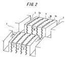
- FIG. 2 is a partially enlarged perspective view showing blocks in the tread pattern shown in FIG. 1 .
- FIG. 3 is a sectional perspective view cut along the III-III line of FIG. 2 .
- the reference number 1 represents a contact surface of a tread
- 2 represents plural annular circumferential grooves provided in the contact surface 1 of the tread to extend in the circumferential direction
- 3 represents plural lateral grooves extending in the tread widthwise direction to intersect the respective circumferential grooves
- 4 represents a block defined by the plural circumferential grooves 2 and the plural lateral grooves
- 5 represents plural sipes provided in each block 4 to extend so as to be more inclined toward the tread widthwise direction than the tread circumferential direction.
- each of the circumferential grooves in the contact surface 1 of the tread, four circumferential grooves 2 extending linearly in the tread circumferential direction are provided such that the width and the depth of each of the circumferential grooves are 5.0 to 8.0 mm and 8 to 9 mm, respectively and plural lateral grooves 3 extending in the tread widthwise direction to intersect these circumferential grooves 2 are provided such that the width and the depth of each of the lateral grooves are 3.0 to 7.0 mm and 7 to 9 mm, respectively, such that five rows of block rows 6 are defined between the grooves 2, 3 and the tread side ends.
- sipes 5 each having, for example, what is called a three-dimensional configuration including the width in the range of 5 to 40 mm and the depth in the range of 6.0 to 10.0 mm are formed in each block 4 of respective block rows 6 such that each sipe extends to be more inclined toward the tread widthwise direction than the tread circumferential direction.
- the sipe 5 shown in the drawings is a three-dimensional sipe extending in a zigzag form in both tread widthwise and depth directions.
- each projection 7 has the length along the sipe bottom, which length is in the range of 0.2 to 2.0 mm, and the depth of the upper end of the projection measured from a block surface, which is in the range of 20 to 80% of the sipe depth.
- each projection 7 By setting the length along the sipe bottom of each projection 7 in the range of 0.2 to 2.0 mm, collapse-deformation of sectioned portions 8 of each block can be suppressed to ensure a sufficiently large ground contact area on a general road surface such as a dry or wet road surface, as well as on an icy or snowy road surface, and water can be reliably drained into the sipes. That is, driving stability can be improved accordingly.
- the sectioned portions 8 of each block collapse-deform in an adequate manner when the tire is used as a brand-new tire on an icy road surface and therefore an edge effect and an effect of removing a water film can be both obtained.
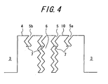
- FIG. 4 is a sectional view cut along the IV-IV line of FIG. 2 .
- FIG. 5 is a sectional view in the tread circumferential direction of a block formed at the contact surface of the tread of FIG. 1 and a graph showing the number of projections provided in respective sipes of the block.
- the number of the projections 7 provided in the leading-side sipe 5a located on the most-leading side of the block 4 and the number of the projections 7 provided in the trailing-side sipe 5b located on the most-trailing side of the block 4 are larger than the number of the projections 7 provided in a sipe located in the middle portion of the block 4, respectively.
- sectioned portions 8 of each block 4 in the vicinity of the middle portion thereof naturally experience a relatively small degree of collapse-deformation due to support provided by the other sectioned portions 8 adjacent thereto when an external force is exerted thereon.
- the sectioned portions 8 of each block 4 located on the most-leading side and the most-trailing side may experience a relatively large degree of collapse-deformation thereof when a relatively large force is exerted on the block 4 because these outermost sectioned portions 8 have no or hardly any other sectioned portions 8 adjacent thereto that would support them, which relatively large degree of collapse-deformation may deteriorate a ground contact area.
- the number(s) of the projections 7 in a sipe/sipes located on the most-leading side 5a or/and the most-trailing side 5b of the block 4 (the numbers of the projections 7 in the respective sipes 5a, 5b in FIG. 5 ) is made larger than the number of the projections 7 in a sipe located in the middle portion of the block 4, so that the force by which the sectioned portions 8 located on the most-leading side and the most-trailing side of the block 4 support each other, i.e. collapse-constraining force against warping-deformation, can be strengthened.
- a ground contact area is effectively prevented from decreasing, whereby driving performance and braking performance on an icy or snowy road surface improve and driving stability on a general road surface also improves.
- an effect of ensuring the water-removing function at the block center, with preventing the block edges from collapse-deforming can be obtained by gradually increasing the number of the projections 7 provided in the sipes of the block 4 from the middle portion toward the leading and the trailing sides of the block.
- a ground contact area increases, whereby driving performance and braking performance on an icy or snowy road surface improve and driving stability on a general road surface also improves.
- the number of the projections 7 provided in the leading-side sipe 5a of each block 4 and the number of the projections 7 provided in the trailing-side sipe 5b of the block are the same.
- the numbers of the projections 7 of the respective sipes 5a, 5b may differ from each other.
- the ratio of the number of the projections 7 in a sipe located in the middle portion of a block 4, with respect to the number/numbers of the projections 7 in the most-leading side sipe 5a or/and the most-trailing side sipe 5b of the block 4, is set in the range of 0.2:1 to 1:1 and specifically at 0.5:1.
- the total sectional area/areas of the projections 7 in the most-leading side sipe 5a or/and the most-trailing side sipe 5b of the block 4 is made larger than the total sectional area of the projections 7 in a sipe located in the middle portion of the block 4.
- the total sectional area of the projections 7 in each sipe of the block 4 is gradually increased from the middle portion toward the most-leading side sipe 5a and the most-trailing side sipe 5b of the block 4, whereby there can be obtained an effect of ensuring the water-removing function at the center of the block, while preventing the block ends from collapse-deforming.
- a ground contact area increases and thus driving performance and braking performance on an icy or snowy road surface improve and driving stability on a general road surface also improves.
- the total sectional area of the projections 7 provided in the most-leading side sipe 5a and the total sectional area of the projections 7 provided in the most-trailing side sipe 5b, of the block 4, may be either identical or different from each other.
- the ratio of the total sectional area of the projections 7 in a sipe 5 located in the middle portion of the block 4, with respect to the total sectional area/areas of the projections 7 in the most-leading side sipe 5a or/and the most-trailing side sipe 5b of the block 4, is set in the range of 0.1:1 to 1:1 and particularly at 0.5:1.
- each of the four sipes 5 formed in the block 4 is provided with the projection 7.
- the projection 7 may be provided to only some of the sipes 5 formed in the block 4.
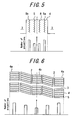
- FIG. 6 is a developed plan view showing respective five block rows of the tread pattern shown in FIG. 1 and a graph showing the respective total numbers of projections in sipes provided in the blocks of the respective block rows.
- the total number/numbers of the projections 7 in the sipes 5 of the block/blocks located on one outermost side/on respective outermost sides in the widthwise direction of the tread are preferably set larger than the total number of the projections 7 in the respective sipes 5 of the center-region block 4b as a block in the center region of the tread.
- the side-region block 4a primarily affects braking performance and/or cornering performance and the center-region block 4b primarily affects braking performance and driving performance.
- respective blocks 4 in plural block rows demarcated by a plurality of the circumferential grooves 2 and the lateral grooves 3 the total number of the projections 7 in the sipes 5 of a side-region block 4a located on one outermost side in the widthwise direction of a tread or the total numbers of the projections 7 in the sipes 5 of side-region blocks 4a, 4a located on respective outermost sides in the widthwise direction of a tread (the total members of the respective side-region blocks 4a, 4a in FIG.
- the sectioned portions 8 of the side-region block 4a can ensure sufficient rigidity due to mutual support therebetween by way of the projections 7 and braking performance on an icy or snowy road and driving stability on a general road can be improved.
- the sipes 5 in the center-region block 4b are provided with a relatively small total number of the projections 7, whereby mutual support between the sectioned portions 8 by way of the projections 7 is decreased and the sectioned portions 8 of the block 4b are subjected to an adequate degree of warping-deformation.
- the edge effect by the sipe edges is further enhanced and braking performance and acceleration performance on an icy or snowy road can be improved. Accordingly, braking performance, acceleration performance and driving stability can be simultaneously improved by effecting an optimal change in distribution of the total number of the projections 7 in the pattern.
- the total number of the projections 7 in the sipes 5 provided in the block 4 is gradually increased from the center-region block 4b toward the side-region blocks 4a so that the number of the projections 7 decreases and the edge effect enhances toward the center-region 4b.
- driving performance and braking performance on an icy or snowy road improve.
- driving stability on a general road also improves.
- the total number of the projections 7 provided in one side-region block 4a and the total number of the projections 7 provided in the other side-region block 4a are the same. However, the aforementioned total numbers of the projections 7 may be different from each other.
- the ratio of the total number of the projections 7 in the sipes 5 of the center-region block 4b with respect to the total number(s) of the projections 7 in the sipes 5 of at least one of the side-region blocks 4a, 4a is set in the range of 0.2:1 to 1: 1 and particularly set at 0.25:1.
- the total sectional area(s) of the projections 7 in the sipes 5 of at least one of the side-region blocks 4a, 4a is set larger than the total sectional area of the projections 7 in the sipes 5 of the center-region block 4b.
- rigidity of a shoulder portion of the tread in a cornering situation, as well as the edge effect at the center portion of the tread, which center portion is mainly for use in acceleration, is likely to be obtained.
- a sectional area of the projections 7 in the sipes 5 provided in each block 4 is gradually increased from the center-region block 4b toward the side-region blocks 4a so that the sectional area of the projections 7 decreases and the edge effect enhances toward the center-region 4b.
- the sectional area of the projections 7 provided in one side-region block 4a and the sectional area of the projections 7 provided in the other side-region block 4a, of the block 4, may be either the same or different from each other.
- the ratio of the total sectional area of the projections 7 in the sipes 5 of the center-region block 4b with respect to the total sectional area(s) of the projections 7 in the sipes 5 of at least one of the side-region blocks 4a, 4a is set in the range of 0.1:1 to 1:1 and particularly set at 0.25:1.
- the extending configuration of the sipe 5 opening to a surface of the block 4 is not limited to a zigzag shape and may have a linear, crank-like or other required shape. Either one end or both ends of the sipe 5 may terminate within the block 4.
- the sipe 5 may be formed to have either a two-dimensional configuration or a three-dimensional configuration. Accordingly, although the sipe 5 is a three-dimensional sipe in the drawings, the sipe 5 may be structured as a two-dimensional sipe.
- FIG. 7 is a sectional perspective view exemplarily showing a blade which is mounted to a vulcanization mold and can be used for forming the sipe 5 and the projection 7 in the sipe 5.
- FIG. 8 is a front view of the blade shown in FIG. 7 .
- the sipe 5 provided with the projection 7 in the present invention
- a slit in the blade 11 allows rubber to intrude therein and this rubber portion forms a projection 7, while the blade 11 itself expels rubber and thus forms a sipe 5.
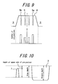
- test radial tires each having size of 195/65R15, pitch of 56 and a structure as show in FIGS. 1 , 9 and 10 were produced.
- the characteristics of the test tires were varied, respectively, to be Example 1 tire, Example 2 tire, Example 3 tire and Comparative Example 1 tire.
- the acceleration performance on an icy or snowy road was analyzed for the respective test tires.
- each of the four circumferential grooves has a dimension of width: 5 mm and depth: 9 mm and each of the lateral grooves has a dimension of width: 5 mm and depth: 9 mm.
- Four three-dimensional sipes each having width: 30 mm and depth: 7 mm are formed in each block of the respective five block rows defined in the tread circumferential direction.
- Each sipe is provided with a projection having width: 0.5 mm and depth which is 56% of the sipe depth.
- the number of the projections provided in the pattern as a whole are set to be the same among the respective test tires.
- the tire structures other than a contact surface of a tread, of the test tires, are substantially the same as those of the conventional radial tire because these structures need no modification in the present invention.
- Example 1 tire projections are provided to be evenly distributed throughout all sipes and three projections are provided with 7 mm interval therebetween in each sipe.
- Example 2 tire the respective sipes located on the leading side and the trailing side of each block are provided with four projections with 5 mm intervals therebetween and the respective sipes located in the middle portion of the block are provided with two projections with a 10 mm interval therebetween.
- Example 3 tire the blocks included in the tread center region in the tread pattern are each provided with a projection, the blocks adjacent to the center-region blocks are each provided with three sipes with 7 mm intervals therebetween, and the blocks on the respective tread side regions are each provided with four projections with 5 mm intervals therebetween.
- no projections are provided in sipes thereof.
- Example 2 tire where the numbers of projections in sipes located on the most-leading side and the most-trailing side of each block are set larger than the number of projections in sipes located at the middle portion of the block, exhibits relatively small decrease in a ground contact area of the tread portion and good braking performance.
- Example 3 From the results shown in Table 3, it is understood that the tires of Examples 1 to 3, where the projections inside the sipes reinforce each block, exhibit better cornering performance on a general road than the tire of Comparative Example 1. Further, it is understood that Example 3 tire exhibits the highest rigidity of the blocks on the respective tread side regions and is satisfactory.
Landscapes
- Engineering & Computer Science (AREA)
- Mechanical Engineering (AREA)
- Tires In General (AREA)
Claims (9)
- Radialluftreifen, der umfasst: eine Lauffläche mit einer Aufstandsfläche (1); mehrere Umfangsrillen (2), die in der Aufstandsfläche der Lauffläche vorhanden sind, um sich jeweils in der Umfangsrichtung der Lauffläche zu erstrecken; mehrere seitliche Rillen (3), die in der Aufstandsfläche (1) der Lauffläche vorhanden sind, um sich jeweils in der Breitenrichtung der Lauffläche so zu erstrecken, dass sie die Umfangsrillen (2) schneiden; Blöcke (4), die durch die Umfangsrillen (2) und die seitlichen Rillen (3) in der Aufstandsfläche der Lauffläche begrenzt werden; und mehrere Lamellen (5), die in den Blöcken (4) vorhanden sind, die sich so erstrecken, dass sie zur Breitenrichtung der Lauffläche stärker geneigt sind als zur Umfangsrichtung der Lauffläche, wobei
der untere Abschnitt einer jeden Lamelle (5) mit mindestens einem radial nach außen vorstehenden Vorsprung (7) für das zusammenhängende Verbinden der jeweiligen gegenüberliegenden Rillenwände der Lamelle versehen ist; dadurch gekennzeichnet, dass:die Anzahl der Vorsprünge (7) in der Lamelle/den Lamellen (5a, 5b), die auf der vordersten Seite oder/und der hintersten Seite eines Blockes (4) angeordnet sind, größer ist als die Anzahl der Vorsprünge in einer Lamelle (5), die im mittleren Abschnitt des Blockes angeordnet sind. - Radialluftreifen nach Anspruch 1, bei dem eine Länge längs des Lamellenbodens eines jeden Vorsprunges (7) im Bereich von 0,2 bis 2,0 mm und eine Tiefe des oberen Endes des Vorsprunges, gemessen von der Oberfläche des Blockes (4), im Bereich von 20 bis 80 % der Lamellentiefe liegt.
- Radialluftreifen nach Anspruch 1 oder Anspruch 2, bei dem das Verhältnis der Anzahl der Vorsprünge (7) in einer Lamelle (5), die im mittleren Abschnitt eines Blockes angeordnet sind, mit Bezugnahme auf die Anzahl der Vorsprünge (7) in einer Lamelle/Lamellen (5a, 5b), die auf der vordersten Seite oder/und der hintersten Seite eines Blockes angeordnet sind, im Bereich von [0,2:1 bis 1:1) liegt.
- Radialluftreifen nach einem der Ansprüche 1 bis 3, bei dem die gesamte Querschnittsfläche/Querschnittsflächen der Vorsprünge (7) in einer Lamelle/Lamellen (5a, 5b), die auf der vorderen Seite oder/und der hintersten Seite des Blockes (4) angeordnet sind, gleich oder größer ist/sind als die gesamte Querschnittsfläche der Vorsprünge in einer Lamelle (5), die im mittleren Abschnitt des Blockes angeordnet ist.
- Radialluftreifen nach Anspruch 4, bei dem das Verhältnis der gesamten Querschnittsfläche der Vorsprünge (7) in einer Lamelle (5), die im mittleren Abschnitt eines Blockes (4) angeordnet sind, mit Bezugnahme auf die gesamte Querschnittsfläche/Querschnittsflächen der Vorsprünge (7) in einer Lamelle/Lamellen (5a, 5b), die auf der vordersten Seite oder/und der hintersten Seite eines Blockes (4) angeordnet sind, im Bereich von [0,1:1 bis 1:1) liegt.
- Radialluftreifen nach einem der Ansprüche 1 bis 5, bei dem betreffs der jeweiligen Blöcke (4) in mehreren Blockreihen (6), die durch die mehreren Umfangsrillen (2) und die mehreren seitlichen Rillen (3) begrenzt werden, die Gesamtanzahl der Vorsprünge (7) in den Lamellen (5) des Blockes/der Blöcke (4a), die auf einer äußersten Seite/auf den jeweiligen äußersten Seiten in der Breitenrichtung einer Lauffläche angeordnet sind, gleich oder größer ist als die gesamte Anzahl der Vorsprünge (7) in den Lamellen (5) eines Blockes (4b), die im mittleren Bereich der Lauffläche angeordnet sind.
- Radialluftreifen nach Anspruch 6, bei dem das Verhältnis der gesamten Anzahl der Vorsprünge (7) in den Lamellen (5) des Blockes (4b), die im mittleren Bereich der Lauffläche angeordnet sind, mit Bezugnahme auf die gesamte Anzahl der Vorsprünge (7) in den Lamellen (5) eines Blockes/der Blöcke (4a), die auf einer äußersten Seite/auf den jeweiligen äußersten Seiten in der Breitenrichtung einer Lauffläche angeordnet sind, im Bereich von [0,2:1 bis 1:1) liegt.
- Radialluftreifen nach einem der Ansprüche 1 bis 7, bei dem betreffs der jeweiligen Blöcke (4) in mehreren Blockreihen (6), die durch die mehreren Umfangsrillen (2) und die mehreren seitlichen Rillen (3) begrenzt werden, die gesamte Querschnittsfläche/Querschnittsflächen der Vorsprünge (7) in den Lamellen (5) des Blockes/der Blöcke (4a), die auf einer äußersten Seite/auf den jeweiligen äußersten Seiten in der Breitenrichtung einer Lauffläche angeordnet sind, gleich oder größer ist als die gesamte Querschnittsfläche der Vorsprünge (7) in den Lamellen (5) eines Blockes (4b), die im mittleren Bereich der Lauffläche angeordnet sind.
- Radialluftreifen nach Anspruch 8, bei dem das Verhältnis der gesamten Querschnittsfläche der Vorsprünge (7) in den Lamellen (5) des Blockes (4b), die im mittleren Bereich der Lauffläche angeordnet sind, mit Bezugnahme auf die gesamte Querschnittsfläche/Querschnittsflächen der Vorsprünge (7) in den Lamellen (5) eines Blockes/der Blöcke (4a), die auf einer äußersten Seite/auf den jeweiligen äußersten Seiten in der Breitenrichtung einer Lauffläche angeordnet sind, im Bereich von [0,1:1 bis 1:1) liegt.
Applications Claiming Priority (2)
| Application Number | Priority Date | Filing Date | Title |
|---|---|---|---|
| JP2007177502A JP2009012648A (ja) | 2007-07-05 | 2007-07-05 | 空気入りラジアルタイヤ |
| PCT/JP2008/061897 WO2009005056A1 (ja) | 2007-07-05 | 2008-07-01 | 空気入りラジアルタイヤ |
Publications (3)
| Publication Number | Publication Date |
|---|---|
| EP2177376A1 EP2177376A1 (de) | 2010-04-21 |
| EP2177376A4 EP2177376A4 (de) | 2011-09-07 |
| EP2177376B1 true EP2177376B1 (de) | 2013-06-12 |
Family
ID=40226101
Family Applications (1)
| Application Number | Title | Priority Date | Filing Date |
|---|---|---|---|
| EP08777748.8A Not-in-force EP2177376B1 (de) | 2007-07-05 | 2008-07-01 | Radialluftreifen |
Country Status (5)
| Country | Link |
|---|---|
| US (1) | US9409446B2 (de) |
| EP (1) | EP2177376B1 (de) |
| JP (1) | JP2009012648A (de) |
| CN (1) | CN101784401B (de) |
| WO (1) | WO2009005056A1 (de) |
Families Citing this family (17)
| Publication number | Priority date | Publication date | Assignee | Title |
|---|---|---|---|---|
| JP5215903B2 (ja) * | 2009-02-19 | 2013-06-19 | 東洋ゴム工業株式会社 | 空気入りタイヤ |
| JP2010254154A (ja) * | 2009-04-24 | 2010-11-11 | Bridgestone Corp | タイヤ |
| EP2448775A4 (de) * | 2009-06-29 | 2013-01-23 | Michelin Rech Tech | Verfahren und konstruktion für verbesserte traktion im schnee, verminderten strassenverschleiss und erhöhte geländeleistung |
| ITPD20110087A1 (it) * | 2011-03-21 | 2012-09-22 | Pirelli | Pneumatico invernale |
| US9566829B2 (en) | 2012-02-01 | 2017-02-14 | Bridgestone Corporation | Pneumatic tire |
| JP5835112B2 (ja) * | 2012-06-05 | 2015-12-24 | 横浜ゴム株式会社 | 空気入りタイヤ |
| NL2009980C2 (en) * | 2012-12-13 | 2014-06-16 | Ct Voor Tech Informatica B V | A method of producing glass products from glass product material and an assembly for performing said method. |
| JP6086836B2 (ja) * | 2013-07-25 | 2017-03-01 | 株式会社ブリヂストン | 空気入りタイヤ |
| US10926586B2 (en) | 2013-12-26 | 2021-02-23 | Bridgestone Americas Tire Operations, Llc | Tire tread having a flexible gate apparatus |
| JP6329010B2 (ja) * | 2014-06-13 | 2018-05-23 | 株式会社ブリヂストン | 空気入りタイヤ |
| FR3022493B1 (fr) * | 2014-06-24 | 2016-07-01 | Michelin & Cie | Bande de roulement incisee pour pneu genie civil |
| JP6699245B2 (ja) * | 2016-03-04 | 2020-05-27 | 住友ゴム工業株式会社 | 空気入りタイヤ |
| JP7225490B2 (ja) | 2019-02-15 | 2023-02-21 | Toyo Tire株式会社 | 空気入りタイヤ |
| KR102185593B1 (ko) * | 2019-04-16 | 2020-12-03 | 한국타이어앤테크놀로지 주식회사 | 중하중용 타이어의 트레드블록 |
| JP6888706B1 (ja) * | 2020-03-04 | 2021-06-16 | 横浜ゴム株式会社 | タイヤ |
| JP7494491B2 (ja) | 2020-03-06 | 2024-06-04 | 住友ゴム工業株式会社 | タイヤ |
| JP2024087558A (ja) * | 2022-12-19 | 2024-07-01 | 住友ゴム工業株式会社 | タイヤ |
Family Cites Families (21)
| Publication number | Priority date | Publication date | Assignee | Title |
|---|---|---|---|---|
| JPS63137003A (ja) * | 1986-11-29 | 1988-06-09 | Yokohama Rubber Co Ltd:The | 雪氷路用タイヤ |
| JPH061442Y2 (ja) * | 1987-02-19 | 1994-01-12 | 株式会社ブリヂストン | 空気入りラジアルタイヤ |
| JPH0325007A (ja) * | 1989-06-23 | 1991-02-01 | Toyo Tire & Rubber Co Ltd | ラジアルタイヤ |
| JPH0392403A (ja) * | 1989-09-04 | 1991-04-17 | Bridgestone Corp | サイプつきブロックパターンを有する空気入りタイヤ |
| JP2906067B2 (ja) * | 1989-11-29 | 1999-06-14 | 横浜ゴム株式会社 | 空気入りスタッドレスタイヤ |
| JPH06219108A (ja) * | 1993-01-22 | 1994-08-09 | Yokohama Rubber Co Ltd:The | 雪氷路用タイヤ |
| JP3079026B2 (ja) * | 1995-11-15 | 2000-08-21 | 住友ゴム工業株式会社 | スタッドレスタイヤ |
| JP3471503B2 (ja) * | 1995-11-20 | 2003-12-02 | 横浜ゴム株式会社 | 空気入りタイヤ |
| JPH10151915A (ja) * | 1996-11-21 | 1998-06-09 | Sumitomo Rubber Ind Ltd | 空気入りタイヤ |
| JP3709256B2 (ja) * | 1997-05-08 | 2005-10-26 | 株式会社ブリヂストン | 空気入りタイヤ |
| JP3273772B2 (ja) * | 1999-12-07 | 2002-04-15 | 住友ゴム工業株式会社 | スタッドレスタイヤ |
| DE60017329T2 (de) | 1999-10-06 | 2005-12-01 | Sumitomo Rubber Industries Ltd., Kobe | Spikeloser Reifen |
| JP3273771B2 (ja) * | 1999-10-06 | 2002-04-15 | 住友ゴム工業株式会社 | 空気入りタイヤ |
| JP3894743B2 (ja) * | 2001-04-05 | 2007-03-22 | 横浜ゴム株式会社 | 空気入りタイヤ |
| JP4340112B2 (ja) * | 2003-08-20 | 2009-10-07 | 住友ゴム工業株式会社 | 空気入りタイヤ |
| JP4377649B2 (ja) * | 2003-10-15 | 2009-12-02 | 住友ゴム工業株式会社 | 空気入りタイヤ |
| JP4414726B2 (ja) * | 2003-10-30 | 2010-02-10 | 住友ゴム工業株式会社 | 空気入りタイヤ |
| JP2006062468A (ja) * | 2004-08-25 | 2006-03-09 | Bridgestone Corp | 空気入りタイヤ |
| JP4521285B2 (ja) | 2005-01-14 | 2010-08-11 | 株式会社ブリヂストン | 空気入りタイヤ |
| JP2007055285A (ja) | 2005-08-22 | 2007-03-08 | Bridgestone Corp | 空気入りタイヤおよび空気入りタイヤの製造方法 |
| JP4730952B2 (ja) * | 2005-09-05 | 2011-07-20 | 東洋ゴム工業株式会社 | 空気入りタイヤ |
-
2007
- 2007-07-05 JP JP2007177502A patent/JP2009012648A/ja active Pending
-
2008
- 2008-07-01 EP EP08777748.8A patent/EP2177376B1/de not_active Not-in-force
- 2008-07-01 WO PCT/JP2008/061897 patent/WO2009005056A1/ja active Application Filing
- 2008-07-01 US US12/667,572 patent/US9409446B2/en not_active Expired - Fee Related
- 2008-07-01 CN CN2008801040189A patent/CN101784401B/zh not_active Expired - Fee Related
Also Published As
| Publication number | Publication date |
|---|---|
| US9409446B2 (en) | 2016-08-09 |
| US20100212794A1 (en) | 2010-08-26 |
| CN101784401A (zh) | 2010-07-21 |
| JP2009012648A (ja) | 2009-01-22 |
| CN101784401B (zh) | 2013-02-20 |
| EP2177376A4 (de) | 2011-09-07 |
| WO2009005056A1 (ja) | 2009-01-08 |
| EP2177376A1 (de) | 2010-04-21 |
Similar Documents
| Publication | Publication Date | Title |
|---|---|---|
| EP2177376B1 (de) | Radialluftreifen | |
| US10836215B2 (en) | Tire | |
| EP2436535B1 (de) | Reifenlauffläche | |
| EP2163405B1 (de) | Luftreifen | |
| EP3521064B1 (de) | Reifen | |
| US7637295B2 (en) | Pneumatic tire with tread including sipes having bent portions formed with zigzag shape with amplitude in radial direction | |
| JP5115487B2 (ja) | 空気入りタイヤ | |
| EP3135504B1 (de) | Schwerlastreifen | |
| EP2692543B1 (de) | Luftreifen | |
| KR101808870B1 (ko) | 공기 타이어 | |
| CN108290456B (zh) | 轮胎 | |
| CN110662660B (zh) | 充气轮胎 | |
| US20130020001A1 (en) | Pneumatic tire | |
| CN108621710B (zh) | 充气轮胎 | |
| KR20110043462A (ko) | 공기 타이어 | |
| JP2007106314A (ja) | 空気入りタイヤ | |
| CN108349323B (zh) | 轮胎 | |
| JP4614791B2 (ja) | 空気入りタイヤ | |
| JP4020685B2 (ja) | 空気入りタイヤ | |
| CN114683776B (zh) | 充气轮胎 | |
| JP4878987B2 (ja) | 空気入りタイヤ | |
| CN114683777B (zh) | 充气轮胎 | |
| CN114746285B (zh) | 充气轮胎 | |
| EP1167084B1 (de) | Luftreifen | |
| JP7494491B2 (ja) | タイヤ |
Legal Events
| Date | Code | Title | Description |
|---|---|---|---|
| PUAI | Public reference made under article 153(3) epc to a published international application that has entered the european phase |
Free format text: ORIGINAL CODE: 0009012 |
|
| 17P | Request for examination filed |
Effective date: 20100111 |
|
| AK | Designated contracting states |
Kind code of ref document: A1 Designated state(s): AT BE BG CH CY CZ DE DK EE ES FI FR GB GR HR HU IE IS IT LI LT LU LV MC MT NL NO PL PT RO SE SI SK TR |
|
| AX | Request for extension of the european patent |
Extension state: AL BA MK RS |
|
| DAX | Request for extension of the european patent (deleted) | ||
| A4 | Supplementary search report drawn up and despatched |
Effective date: 20110805 |
|
| RIC1 | Information provided on ipc code assigned before grant |
Ipc: B60C 11/12 20060101AFI20110801BHEP |
|
| GRAP | Despatch of communication of intention to grant a patent |
Free format text: ORIGINAL CODE: EPIDOSNIGR1 |
|
| GRAS | Grant fee paid |
Free format text: ORIGINAL CODE: EPIDOSNIGR3 |
|
| GRAA | (expected) grant |
Free format text: ORIGINAL CODE: 0009210 |
|
| AK | Designated contracting states |
Kind code of ref document: B1 Designated state(s): AT BE BG CH CY CZ DE DK EE ES FI FR GB GR HR HU IE IS IT LI LT LU LV MC MT NL NO PL PT RO SE SI SK TR |
|
| REG | Reference to a national code |
Ref country code: GB Ref legal event code: FG4D |
|
| REG | Reference to a national code |
Ref country code: CH Ref legal event code: EP |
|
| REG | Reference to a national code |
Ref country code: AT Ref legal event code: REF Ref document number: 616534 Country of ref document: AT Kind code of ref document: T Effective date: 20130615 |
|
| REG | Reference to a national code |
Ref country code: IE Ref legal event code: FG4D |
|
| REG | Reference to a national code |
Ref country code: DE Ref legal event code: R096 Ref document number: 602008025317 Country of ref document: DE Effective date: 20130808 |
|
| REG | Reference to a national code |
Ref country code: SE Ref legal event code: TRGR |
|
| PG25 | Lapsed in a contracting state [announced via postgrant information from national office to epo] |
Ref country code: GR Free format text: LAPSE BECAUSE OF FAILURE TO SUBMIT A TRANSLATION OF THE DESCRIPTION OR TO PAY THE FEE WITHIN THE PRESCRIBED TIME-LIMIT Effective date: 20130913 Ref country code: SI Free format text: LAPSE BECAUSE OF FAILURE TO SUBMIT A TRANSLATION OF THE DESCRIPTION OR TO PAY THE FEE WITHIN THE PRESCRIBED TIME-LIMIT Effective date: 20130612 Ref country code: LT Free format text: LAPSE BECAUSE OF FAILURE TO SUBMIT A TRANSLATION OF THE DESCRIPTION OR TO PAY THE FEE WITHIN THE PRESCRIBED TIME-LIMIT Effective date: 20130612 Ref country code: NO Free format text: LAPSE BECAUSE OF FAILURE TO SUBMIT A TRANSLATION OF THE DESCRIPTION OR TO PAY THE FEE WITHIN THE PRESCRIBED TIME-LIMIT Effective date: 20130912 Ref country code: ES Free format text: LAPSE BECAUSE OF FAILURE TO SUBMIT A TRANSLATION OF THE DESCRIPTION OR TO PAY THE FEE WITHIN THE PRESCRIBED TIME-LIMIT Effective date: 20130923 |
|
| REG | Reference to a national code |
Ref country code: AT Ref legal event code: MK05 Ref document number: 616534 Country of ref document: AT Kind code of ref document: T Effective date: 20130612 |
|
| REG | Reference to a national code |
Ref country code: NL Ref legal event code: VDEP Effective date: 20130612 |
|
| REG | Reference to a national code |
Ref country code: LT Ref legal event code: MG4D |
|
| PG25 | Lapsed in a contracting state [announced via postgrant information from national office to epo] |
Ref country code: BG Free format text: LAPSE BECAUSE OF FAILURE TO SUBMIT A TRANSLATION OF THE DESCRIPTION OR TO PAY THE FEE WITHIN THE PRESCRIBED TIME-LIMIT Effective date: 20130912 Ref country code: HR Free format text: LAPSE BECAUSE OF FAILURE TO SUBMIT A TRANSLATION OF THE DESCRIPTION OR TO PAY THE FEE WITHIN THE PRESCRIBED TIME-LIMIT Effective date: 20130612 |
|
| PG25 | Lapsed in a contracting state [announced via postgrant information from national office to epo] |
Ref country code: LV Free format text: LAPSE BECAUSE OF FAILURE TO SUBMIT A TRANSLATION OF THE DESCRIPTION OR TO PAY THE FEE WITHIN THE PRESCRIBED TIME-LIMIT Effective date: 20130612 |
|
| PG25 | Lapsed in a contracting state [announced via postgrant information from national office to epo] |
Ref country code: BE Free format text: LAPSE BECAUSE OF FAILURE TO SUBMIT A TRANSLATION OF THE DESCRIPTION OR TO PAY THE FEE WITHIN THE PRESCRIBED TIME-LIMIT Effective date: 20130612 Ref country code: IS Free format text: LAPSE BECAUSE OF FAILURE TO SUBMIT A TRANSLATION OF THE DESCRIPTION OR TO PAY THE FEE WITHIN THE PRESCRIBED TIME-LIMIT Effective date: 20131012 Ref country code: SK Free format text: LAPSE BECAUSE OF FAILURE TO SUBMIT A TRANSLATION OF THE DESCRIPTION OR TO PAY THE FEE WITHIN THE PRESCRIBED TIME-LIMIT Effective date: 20130612 Ref country code: AT Free format text: LAPSE BECAUSE OF FAILURE TO SUBMIT A TRANSLATION OF THE DESCRIPTION OR TO PAY THE FEE WITHIN THE PRESCRIBED TIME-LIMIT Effective date: 20130612 Ref country code: PT Free format text: LAPSE BECAUSE OF FAILURE TO SUBMIT A TRANSLATION OF THE DESCRIPTION OR TO PAY THE FEE WITHIN THE PRESCRIBED TIME-LIMIT Effective date: 20131014 Ref country code: EE Free format text: LAPSE BECAUSE OF FAILURE TO SUBMIT A TRANSLATION OF THE DESCRIPTION OR TO PAY THE FEE WITHIN THE PRESCRIBED TIME-LIMIT Effective date: 20130612 Ref country code: CZ Free format text: LAPSE BECAUSE OF FAILURE TO SUBMIT A TRANSLATION OF THE DESCRIPTION OR TO PAY THE FEE WITHIN THE PRESCRIBED TIME-LIMIT Effective date: 20130612 |
|
| PG25 | Lapsed in a contracting state [announced via postgrant information from national office to epo] |
Ref country code: RO Free format text: LAPSE BECAUSE OF FAILURE TO SUBMIT A TRANSLATION OF THE DESCRIPTION OR TO PAY THE FEE WITHIN THE PRESCRIBED TIME-LIMIT Effective date: 20130612 Ref country code: PL Free format text: LAPSE BECAUSE OF FAILURE TO SUBMIT A TRANSLATION OF THE DESCRIPTION OR TO PAY THE FEE WITHIN THE PRESCRIBED TIME-LIMIT Effective date: 20130612 Ref country code: NL Free format text: LAPSE BECAUSE OF FAILURE TO SUBMIT A TRANSLATION OF THE DESCRIPTION OR TO PAY THE FEE WITHIN THE PRESCRIBED TIME-LIMIT Effective date: 20130612 |
|
| REG | Reference to a national code |
Ref country code: CH Ref legal event code: PL |
|
| PG25 | Lapsed in a contracting state [announced via postgrant information from national office to epo] |
Ref country code: MC Free format text: LAPSE BECAUSE OF FAILURE TO SUBMIT A TRANSLATION OF THE DESCRIPTION OR TO PAY THE FEE WITHIN THE PRESCRIBED TIME-LIMIT Effective date: 20130612 |
|
| PLBE | No opposition filed within time limit |
Free format text: ORIGINAL CODE: 0009261 |
|
| STAA | Information on the status of an ep patent application or granted ep patent |
Free format text: STATUS: NO OPPOSITION FILED WITHIN TIME LIMIT |
|
| REG | Reference to a national code |
Ref country code: IE Ref legal event code: MM4A |
|
| PG25 | Lapsed in a contracting state [announced via postgrant information from national office to epo] |
Ref country code: DK Free format text: LAPSE BECAUSE OF FAILURE TO SUBMIT A TRANSLATION OF THE DESCRIPTION OR TO PAY THE FEE WITHIN THE PRESCRIBED TIME-LIMIT Effective date: 20130612 Ref country code: CH Free format text: LAPSE BECAUSE OF NON-PAYMENT OF DUE FEES Effective date: 20130731 Ref country code: LI Free format text: LAPSE BECAUSE OF NON-PAYMENT OF DUE FEES Effective date: 20130731 |
|
| 26N | No opposition filed |
Effective date: 20140313 |
|
| GBPC | Gb: european patent ceased through non-payment of renewal fee |
Effective date: 20130912 |
|
| PG25 | Lapsed in a contracting state [announced via postgrant information from national office to epo] |
Ref country code: IT Free format text: LAPSE BECAUSE OF FAILURE TO SUBMIT A TRANSLATION OF THE DESCRIPTION OR TO PAY THE FEE WITHIN THE PRESCRIBED TIME-LIMIT Effective date: 20130612 |
|
| REG | Reference to a national code |
Ref country code: DE Ref legal event code: R097 Ref document number: 602008025317 Country of ref document: DE Effective date: 20140313 |
|
| PG25 | Lapsed in a contracting state [announced via postgrant information from national office to epo] |
Ref country code: IE Free format text: LAPSE BECAUSE OF NON-PAYMENT OF DUE FEES Effective date: 20130701 Ref country code: GB Free format text: LAPSE BECAUSE OF NON-PAYMENT OF DUE FEES Effective date: 20130912 |
|
| REG | Reference to a national code |
Ref country code: DE Ref legal event code: R082 Ref document number: 602008025317 Country of ref document: DE Representative=s name: MARKS & CLERK (LUXEMBOURG) LLP, LU |
|
| REG | Reference to a national code |
Ref country code: FR Ref legal event code: CA Effective date: 20140812 |
|
| REG | Reference to a national code |
Ref country code: DE Ref legal event code: R081 Ref document number: 602008025317 Country of ref document: DE Owner name: BRIDGESTONE CORPORATION, JP Free format text: FORMER OWNER: BRIDGESTONE CORP., TOKIO/TOKYO, JP Effective date: 20140828 Ref country code: DE Ref legal event code: R082 Ref document number: 602008025317 Country of ref document: DE Representative=s name: MARKS & CLERK (LUXEMBOURG) LLP, LU Effective date: 20140828 |
|
| PG25 | Lapsed in a contracting state [announced via postgrant information from national office to epo] |
Ref country code: CY Free format text: LAPSE BECAUSE OF FAILURE TO SUBMIT A TRANSLATION OF THE DESCRIPTION OR TO PAY THE FEE WITHIN THE PRESCRIBED TIME-LIMIT Effective date: 20130612 Ref country code: TR Free format text: LAPSE BECAUSE OF FAILURE TO SUBMIT A TRANSLATION OF THE DESCRIPTION OR TO PAY THE FEE WITHIN THE PRESCRIBED TIME-LIMIT Effective date: 20130612 Ref country code: MT Free format text: LAPSE BECAUSE OF FAILURE TO SUBMIT A TRANSLATION OF THE DESCRIPTION OR TO PAY THE FEE WITHIN THE PRESCRIBED TIME-LIMIT Effective date: 20130612 |
|
| PG25 | Lapsed in a contracting state [announced via postgrant information from national office to epo] |
Ref country code: LU Free format text: LAPSE BECAUSE OF NON-PAYMENT OF DUE FEES Effective date: 20130701 Ref country code: HU Free format text: LAPSE BECAUSE OF FAILURE TO SUBMIT A TRANSLATION OF THE DESCRIPTION OR TO PAY THE FEE WITHIN THE PRESCRIBED TIME-LIMIT; INVALID AB INITIO Effective date: 20080701 |
|
| REG | Reference to a national code |
Ref country code: FR Ref legal event code: PLFP Year of fee payment: 9 |
|
| REG | Reference to a national code |
Ref country code: FR Ref legal event code: PLFP Year of fee payment: 10 |
|
| REG | Reference to a national code |
Ref country code: FR Ref legal event code: PLFP Year of fee payment: 11 |
|
| PGFP | Annual fee paid to national office [announced via postgrant information from national office to epo] |
Ref country code: FI Payment date: 20190722 Year of fee payment: 12 Ref country code: SE Payment date: 20190719 Year of fee payment: 12 |
|
| PGFP | Annual fee paid to national office [announced via postgrant information from national office to epo] |
Ref country code: DE Payment date: 20200721 Year of fee payment: 13 Ref country code: FR Payment date: 20200723 Year of fee payment: 13 |
|
| REG | Reference to a national code |
Ref country code: FI Ref legal event code: MAE |
|
| REG | Reference to a national code |
Ref country code: SE Ref legal event code: EUG |
|
| PG25 | Lapsed in a contracting state [announced via postgrant information from national office to epo] |
Ref country code: FI Free format text: LAPSE BECAUSE OF NON-PAYMENT OF DUE FEES Effective date: 20200701 |
|
| PG25 | Lapsed in a contracting state [announced via postgrant information from national office to epo] |
Ref country code: SE Free format text: LAPSE BECAUSE OF NON-PAYMENT OF DUE FEES Effective date: 20200702 |
|
| REG | Reference to a national code |
Ref country code: DE Ref legal event code: R119 Ref document number: 602008025317 Country of ref document: DE |
|
| PG25 | Lapsed in a contracting state [announced via postgrant information from national office to epo] |
Ref country code: DE Free format text: LAPSE BECAUSE OF NON-PAYMENT OF DUE FEES Effective date: 20220201 |
|
| PG25 | Lapsed in a contracting state [announced via postgrant information from national office to epo] |
Ref country code: FR Free format text: LAPSE BECAUSE OF NON-PAYMENT OF DUE FEES Effective date: 20210731 |