EP2175477B1 - Procede de fabrication de tranche liee - Google Patents
Procede de fabrication de tranche liee Download PDFInfo
- Publication number
- EP2175477B1 EP2175477B1 EP08776766.1A EP08776766A EP2175477B1 EP 2175477 B1 EP2175477 B1 EP 2175477B1 EP 08776766 A EP08776766 A EP 08776766A EP 2175477 B1 EP2175477 B1 EP 2175477B1
- Authority
- EP
- European Patent Office
- Prior art keywords
- wafer
- oxide film
- heat treatment
- bonded wafer
- atmosphere
- Prior art date
- Legal status (The legal status is an assumption and is not a legal conclusion. Google has not performed a legal analysis and makes no representation as to the accuracy of the status listed.)
- Active
Links
- 238000004519 manufacturing process Methods 0.000 title claims description 21
- 238000000034 method Methods 0.000 claims description 100
- 239000010408 film Substances 0.000 claims description 89
- 230000008569 process Effects 0.000 claims description 60
- 239000012298 atmosphere Substances 0.000 claims description 52
- 239000010410 layer Substances 0.000 claims description 38
- 238000010438 heat treatment Methods 0.000 claims description 37
- 239000010409 thin film Substances 0.000 claims description 28
- 239000007789 gas Substances 0.000 claims description 27
- 238000004140 cleaning Methods 0.000 claims description 25
- 230000032798 delamination Effects 0.000 claims description 25
- 238000005468 ion implantation Methods 0.000 claims description 22
- 230000001590 oxidative effect Effects 0.000 claims description 22
- CBENFWSGALASAD-UHFFFAOYSA-N Ozone Chemical compound [O-][O+]=O CBENFWSGALASAD-UHFFFAOYSA-N 0.000 claims description 19
- 239000001257 hydrogen Substances 0.000 claims description 18
- 229910052739 hydrogen Inorganic materials 0.000 claims description 18
- XLYOFNOQVPJJNP-UHFFFAOYSA-N water Substances O XLYOFNOQVPJJNP-UHFFFAOYSA-N 0.000 claims description 17
- UFHFLCQGNIYNRP-UHFFFAOYSA-N Hydrogen Chemical compound [H][H] UFHFLCQGNIYNRP-UHFFFAOYSA-N 0.000 claims description 14
- 239000012300 argon atmosphere Substances 0.000 claims description 4
- 239000000758 substrate Substances 0.000 claims description 3
- 239000002344 surface layer Substances 0.000 claims description 2
- 235000012431 wafers Nutrition 0.000 description 128
- 230000007547 defect Effects 0.000 description 47
- XUIMIQQOPSSXEZ-UHFFFAOYSA-N Silicon Chemical compound [Si] XUIMIQQOPSSXEZ-UHFFFAOYSA-N 0.000 description 27
- 238000002474 experimental method Methods 0.000 description 23
- 230000003647 oxidation Effects 0.000 description 16
- 238000007254 oxidation reaction Methods 0.000 description 16
- 229910052710 silicon Inorganic materials 0.000 description 16
- 239000010703 silicon Substances 0.000 description 16
- 230000000052 comparative effect Effects 0.000 description 15
- 238000005530 etching Methods 0.000 description 15
- 150000002500 ions Chemical class 0.000 description 13
- 238000013508 migration Methods 0.000 description 11
- 230000005012 migration Effects 0.000 description 11
- 230000000694 effects Effects 0.000 description 10
- 239000013078 crystal Substances 0.000 description 9
- 238000005259 measurement Methods 0.000 description 7
- VHUUQVKOLVNVRT-UHFFFAOYSA-N Ammonium hydroxide Chemical compound [NH4+].[OH-] VHUUQVKOLVNVRT-UHFFFAOYSA-N 0.000 description 6
- 230000003746 surface roughness Effects 0.000 description 6
- 230000007423 decrease Effects 0.000 description 5
- 239000011259 mixed solution Substances 0.000 description 5
- 238000007796 conventional method Methods 0.000 description 4
- 230000006866 deterioration Effects 0.000 description 4
- 238000009826 distribution Methods 0.000 description 4
- 238000011156 evaluation Methods 0.000 description 4
- -1 hydrogen ions Chemical class 0.000 description 4
- 238000007788 roughening Methods 0.000 description 4
- 239000007864 aqueous solution Substances 0.000 description 3
- 238000011109 contamination Methods 0.000 description 3
- 230000001698 pyrogenic effect Effects 0.000 description 3
- XKRFYHLGVUSROY-UHFFFAOYSA-N Argon Chemical compound [Ar] XKRFYHLGVUSROY-UHFFFAOYSA-N 0.000 description 2
- 229910052786 argon Inorganic materials 0.000 description 2
- QVGXLLKOCUKJST-UHFFFAOYSA-N atomic oxygen Chemical compound [O] QVGXLLKOCUKJST-UHFFFAOYSA-N 0.000 description 2
- 229910001385 heavy metal Inorganic materials 0.000 description 2
- 238000002513 implantation Methods 0.000 description 2
- 239000011261 inert gas Substances 0.000 description 2
- 239000007788 liquid Substances 0.000 description 2
- 239000001301 oxygen Substances 0.000 description 2
- 229910052760 oxygen Inorganic materials 0.000 description 2
- 239000000243 solution Substances 0.000 description 2
- 239000000853 adhesive Substances 0.000 description 1
- 230000001070 adhesive effect Effects 0.000 description 1
- 238000005054 agglomeration Methods 0.000 description 1
- 230000002776 aggregation Effects 0.000 description 1
- 238000003776 cleavage reaction Methods 0.000 description 1
- 238000001816 cooling Methods 0.000 description 1
- GPRLSGONYQIRFK-UHFFFAOYSA-N hydron Chemical compound [H+] GPRLSGONYQIRFK-UHFFFAOYSA-N 0.000 description 1
- 239000012212 insulator Substances 0.000 description 1
- 238000011835 investigation Methods 0.000 description 1
- 239000000203 mixture Substances 0.000 description 1
- 230000035515 penetration Effects 0.000 description 1
- 238000005498 polishing Methods 0.000 description 1
- 230000008707 rearrangement Effects 0.000 description 1
- 230000007017 scission Effects 0.000 description 1
- 238000000926 separation method Methods 0.000 description 1
Images
Classifications
-
- H—ELECTRICITY
- H01—ELECTRIC ELEMENTS
- H01L—SEMICONDUCTOR DEVICES NOT COVERED BY CLASS H10
- H01L21/00—Processes or apparatus adapted for the manufacture or treatment of semiconductor or solid state devices or of parts thereof
- H01L21/70—Manufacture or treatment of devices consisting of a plurality of solid state components formed in or on a common substrate or of parts thereof; Manufacture of integrated circuit devices or of parts thereof
- H01L21/71—Manufacture of specific parts of devices defined in group H01L21/70
- H01L21/76—Making of isolation regions between components
- H01L21/762—Dielectric regions, e.g. EPIC dielectric isolation, LOCOS; Trench refilling techniques, SOI technology, use of channel stoppers
- H01L21/7624—Dielectric regions, e.g. EPIC dielectric isolation, LOCOS; Trench refilling techniques, SOI technology, use of channel stoppers using semiconductor on insulator [SOI] technology
- H01L21/76251—Dielectric regions, e.g. EPIC dielectric isolation, LOCOS; Trench refilling techniques, SOI technology, use of channel stoppers using semiconductor on insulator [SOI] technology using bonding techniques
- H01L21/76254—Dielectric regions, e.g. EPIC dielectric isolation, LOCOS; Trench refilling techniques, SOI technology, use of channel stoppers using semiconductor on insulator [SOI] technology using bonding techniques with separation/delamination along an ion implanted layer, e.g. Smart-cut, Unibond
-
- H—ELECTRICITY
- H01—ELECTRIC ELEMENTS
- H01L—SEMICONDUCTOR DEVICES NOT COVERED BY CLASS H10
- H01L21/00—Processes or apparatus adapted for the manufacture or treatment of semiconductor or solid state devices or of parts thereof
- H01L21/02—Manufacture or treatment of semiconductor devices or of parts thereof
- H01L21/02041—Cleaning
- H01L21/02057—Cleaning during device manufacture
-
- H—ELECTRICITY
- H01—ELECTRIC ELEMENTS
- H01L—SEMICONDUCTOR DEVICES NOT COVERED BY CLASS H10
- H01L21/00—Processes or apparatus adapted for the manufacture or treatment of semiconductor or solid state devices or of parts thereof
- H01L21/02—Manufacture or treatment of semiconductor devices or of parts thereof
- H01L21/04—Manufacture or treatment of semiconductor devices or of parts thereof the devices having potential barriers, e.g. a PN junction, depletion layer or carrier concentration layer
- H01L21/18—Manufacture or treatment of semiconductor devices or of parts thereof the devices having potential barriers, e.g. a PN junction, depletion layer or carrier concentration layer the devices having semiconductor bodies comprising elements of Group IV of the Periodic Table or AIIIBV compounds with or without impurities, e.g. doping materials
- H01L21/26—Bombardment with radiation
- H01L21/263—Bombardment with radiation with high-energy radiation
- H01L21/265—Bombardment with radiation with high-energy radiation producing ion implantation
- H01L21/26506—Bombardment with radiation with high-energy radiation producing ion implantation in group IV semiconductors
Definitions
- the present invention relates to a method for manufacturing a bonded wafer by using so-called an ion implantation delamination method in which the bonded wafer is manufactured by delaminating a wafer implanted ions after bonding and particularly to a method for manufacturing a bonded wafer in which a damaged layer remaining in a thin film on a surface of the bonded wafer after delaminating etc. can be removed.
- a method for manufacturing a bonded wafer in which the bonded wafer is manufactured by delaminating a wafer implanted ions after bonding (so-called an ion implantation delamination method) has been known.
- an SOI (silicon on insulator) wafer and the like are manufactured by using the method for manufacturing a bonded wafer.
- the method is a technology of (See also Japanese Patent Application Laid-open (kokai) No. H5-211128 ), for example in the case of manufacturing a SOI wafer, forming an oxide film on at least one of two silicon wafers, implanting hydrogen ions or rare gas ions from a surface of the silicon wafer to form a micro bubble layer (an enclosed layer) in the wafer, then bringing the surface of the wafer that is implanted ions into close contact with the surface of the other silicon wafer via the oxide film, then performing heat treatment (delaminating heat treatment) to delaminate one of the wafers as a thin film so that the micro bubble layer is a cleavage plane and consequently providing an SOI wafer.
- heat treatment delaminating heat treatment
- Damage caused by the ion implantation remains in the thin film SOI layer by the conventional ion implantation delamination method as described above. This remaining damage affects device characteristics etc.
- the SOI layer after delamination is subjected process.
- the surface of the SOI layer after delamination is subjected to so-called sacrificial oxidation process to remove a damaged layer caused by the ion implantation.
- Document EP 1045 448 proposes a method for removing a damage on the SOI layer and improving surface roughness by performing heat treatment in a reducing atmosphere without polishing the surface of the SOI wafer obtained by the hydrogen ion delamination method. According to the method, the damage remaining on the SOI layer after delamination and surface roughness of the surface of the SOI layer can be improved, with maintaining thickness uniformity.
- the present inventors have examined the bonded wafer in which the thin film (SOI layer of SOI wafer etc.) on a surface of the bonded wafer after delaminating was subjected to conventional process, e.g. sacrificial oxidation process and measured the surface of the thin film by AFM (Atomic Force Microscope). As a result, the present inventors have discovered there were pits (hereinafter referred to as concave defect) having a diameter of 0.5 to 2 ⁇ m and a depth of 1 to 4 nm in the surface of the thin film. An existence of the concave defect as described above could affect the currently latest device characteristics.
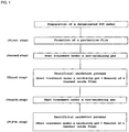
- the present invention provides a method for manufacturing a bonded wafer by an ion implantation delamination method including at least the steps of, bonding a bond wafer having a micro bubble layer formed by gas ion implantation with a base wafer to be a supporting substrate, delaminating the bond wafer along the micro bubble layer as a boundary to form a thin film on the base wafer, the method comprising, in this order, a first step of cleaning the bonded wafer right after delaminating the bond wafer using ozone water; a second step of performing rapid thermal anneal process under a hydrogen containing atmosphere; a third step of forming a thermal oxide film on a surface layer of the bonded wafer by subjecting to heat treatment under an oxidizing gas atmosphere and removing the thermal oxide film; a fourth step of subjecting to heat treatment under a non-oxidizing gas atmosphere.
- an oxide film having a thickness of about 1 nm is formed on the surface of the thin film after delaminating.
- the oxide film is different from a thermal oxide film having a uniform film thickness and has a nonuniform film thickness distribution over the whole surface in a period of micron order.
- the rapid thermal anneal process and sacrificial oxidation process (process of subjecting to heat treatment under an oxidizing gas atmosphere to form a thermal oxide film on a surface of a bonded wafer and removing the thermal oxide film) sufficiently reduce the damage caused by the ion implantation in a delaminating plane. Therefore, an occurrence of local etching is suppressed in heat treatment under a non-oxidizing gas atmosphere thereafter. As a result, the concave defect, which is pit having a depth of nano-level, can be improved. Consequently, a bonded wafer having a flat surface in which the occurrence of the concave defects is reduced can be obtained.
- RTO process is performed after cleaning using ozone water so that an oxide film of 1 to 4 nm in thickness is formed on the surface of the thin film in the first step.
- the oxide film formed in the first step is in the range as described above by RTO (Rapid Thermal Oxidation) process, the oxide film can be surely etched in the second step. Therefore, migration of silicon atoms can sufficiently occur.
- RTO Rapid Thermal Oxidation
- a temperature of the rapid thermal anneal is 1100 °C or more and 1250 °C or less in the rapid thermal anneal of the second step.
- the temperature of the rapid thermal anneal of the second step is 1100 °C or more, migration of silicon atoms can effectively occur. Further, when the temperature of the rapid thermal anneal of the second step is 1250 °C or less, an occurrence of slip dislocation in the SOI wafer can be suppressed and an occurrence of heavy metal contamination from a heat treatment furnace can be prevented.
- the non-oxidizing gas atmosphere is 100% argon atmosphere in the heat treatment of the fourth step.
- a fifth step of forming a thermal oxide film on the surface of the thin film by subjecting to heat treatment under an oxidizing gas atmosphere and removing the thermal oxide film is further performed after the fourth step.
- a thickness of the thin film can be easily adjusted to a desired thickness.
- the method for manufacturing a bonded wafer of the present invention as described above enables significantly reducing the occurrence of concave defects that occur on the surface of the thin film without deterioration of surface roughness of the surface of the thin film. Therefore, the method can respond to the currently latest device adequately, stabilize device characteristics and improve a yield.
- the present inventors made investigation into the thin film of the bonded wafer (e.g. SOI layer of a bonded SOI wafer etc.) manufactured by using the conventional ion implantation delamination method. As a result, it was revealed that the concave defects occurred by AFM measurement of the surface of the thin film. The concave defects have a bad influence on device characteristics.
- the bonded wafer e.g. SOI layer of a bonded SOI wafer etc.
- the present inventors investigated the concave defects in more detail. As a result, it is revealed that the concave defects exist in a density of about 1x10 5 /cm 2 on the surface of the thin film. In the case that the concave defects exist in the density on the surface of the thin film, few concave defects are detected by measurement in 1 to 10 ⁇ m square as an AFM measurement area. However, the concave defects are frequently detected by measurement in relatively wide areas e.g. about 30 ⁇ m square.
- the present inventors thought that if an SOI wafer right after delamination is subjected to rapid thermal anneal process (rapid heating/rapid cooling process) under a hydrogen containing atmosphere, which has a high migration effect of silicon atoms, etching effect is suppressed since heat treatment time is short and consequently the concave defects can be reduced. So the present inventors have performed the following experiments and have made extensive studies.
- the present inventors discovered that a surface state right after rapid thermal anneal process and a final concave defect density are affected by a process before rapid thermal anneal process under a hydrogen atmosphere, such as cleaning performed to the SOI wafer right after delamination (a pretreatment).
- a pretreatment a process before rapid thermal anneal process under a hydrogen atmosphere
- the present inventors found out that when cleaning that forms a thin oxide film is performed as a pretreatment, that is, when the formed oxide film has a certain degree of nonuniform film thickness distribution rather than having a uniform film thickness distribution, the final concave defect density can be suppressed without deterioration of surface roughness right after rapid thermal anneal process, thereby bringing the present invention to completion.
- the present inventors investigated the relationship between processes after delamination and the concave defects concerning a bonded wafer manufactured by using an ion implantation delamination method.
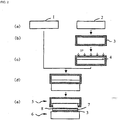
- a SOI wafer was manufactured by an ion implantation delamination method like a conventional method as described below. That is, the SOI wafer was manufactured by the process shown in Fig. 2 .
- process (A) is to prepare two silicon mirror-surface wafers and more specifically, to prepare a base wafer 1 to be a supporting substrate and a bond wafer 2 to be an SOI layer that meet the specification of a device.
- process (b) at least one of the wafers, the bond wafer 2 in this explanation, was subjected to thermal oxidation to form an oxide film 3 having a thickness of about 100 nm to 2000 nm on the wafer surface.
- the oxide film having a thickness of 400 nm was formed.
- gas ions such as hydrogen ions or rare gas ions, hydrogen ions in this explanation, were implanted to one surface of the bond wafer 2 of which the oxide film 3 was formed on its surface to form a microbubble layer (an enclosed layer) 4 parallel to the surface at an average penetration depth of the ions.
- Ion implanting conditions at this time were that the implanted ions were H + ions, implantation energy was 50 keV and dose amount was 5.0x10 16 /cm 2 .
- the hydrogen-ion-implanted surface of the bond wafer 2 to which hydrogen ions were implanted is superposed on the base wafer 1 through the oxide film 3 and brought into close contact with it.
- the wafers are boned together without using adhesives etc.
- the wafers are boned together under room temperature in usual way.
- the bond wafer was delaminated at the enclosed layer 4 as a boundary, thereby separating the bond wafer into a delaminated wafer 5 and an SOI wafer 6 (SOI layer 7 + buried oxide film 3 + base wafer 1).
- heat treatment is conducted under an inert gas atmosphere at a temperature about 400 °C to 600 °C, thereby permitting the separation into the delaminated wafer 5 and the SOI wafer 6 due to crystal rearrangement and agglomeration of bubbles in the enclosed layer.
- the damaged layer 8 remains in SOI layer 7 on the surface of the SOI wafer right after delamination.
- the delaminating heat treatment was performed at 500 °C for 2 hours under N 2 gas atmosphere.
- each SOI wafer after cleaning was subjected to the processes of the surface of the SOI layer.
- the final SOI surface after the processes was measured by AFM to obtain P-V value and concave defect density in 30 ⁇ m square.
- each SOI wafer after cleaning was separately prepared and after RTA process at 1050 °C for 5 seconds under 100% H 2 , the oxide film surface in 2 ⁇ m square was measured by AFM to calculate pit density of the oxide film surface formed by etching effect during the RTA process.
- experiment 2 and 3 the oxide film having a thickness approximately equal to each other was formed by cleaning of the pretreatment, but in experiment 2 in which the oxide film having a low pit density (that is, a high uniformity of the oxide film thickness) was formed, although the P-V value was an adequate value, the concave defect density was one digit higher than experiment 3 and the concave defects could not be sufficiently suppressed. In contrast to this, in experiment 3, a sufficient level of the P-V value and the concave defect density were obtained.
- the P-V value is improved and the damage caused by the ion implantation in a delaminating plane can be reduced, then the occurrence of local etching can be suppressed in heat treatment under a non-oxidizing gas atmosphere and consequently, the concave defect, which is pit having a depth of nano-level, can be improved.
- each thickness of the oxide films formed on the SOI surface was varied to be 3 nm and 4 nm by adding an oxidation process by RTO into each cleaning of two types (ozone water, NH 4 OH/H 2 O 2 /H 2 O mixed solution).
- a method for manufacturing a bonded wafer according to the present invention will be explained referring to Fig. 1 .
- the case of manufacturing a bonded SOI wafer is described by way of example.
- the present invention is not limited thereto. Whenever a bonded wafer is manufactured by an ion implantation delamination method, the present invention can be applied and can be obtained its effects.
- Fig. 1 shows an example flow of steps of the method for manufacturing a bonded wafer of the present invention. It is to be noted that the SOI wafer after delamination manufactured by an ion implantation delamination method can be prepared by the same process as shown in experiments 1 - 7 and Fig. 2 .
- a SOI wafer having a thin film SOI layer on a surface is cleaned using ozone water to form a thin oxide film on the SOI layer surface.
- An ozone concentration of the ozone water is not restricted in particular, it can be 0.1 to 50 ppm for example.
- a temperature of ozone water is usually room temperature but it is not restricted thereto.
- the oxide film having a thin thickness (e.g. about 1 nm) is formed on the SOI layer surface by cleaning using ozone water.
- RTO process is performed after cleaning using ozone water so that the oxide film of 1 to 4 nm in thickness can be formed in the first step.
- the thickness of the oxide film is 4 nm or less, possibility of the occurrence of roughening of a surface by subsequent heat treatments can be eliminated.
- the oxide film formed by cleaning using ozone water having a nonuniform film thickness is removed early at a position (a random position in a plane) where the oxide film thickness is thin to occur etching of a silicon surface exposed then, consequently etching of the silicon surface proceeds at a random position in a plane, a particular crystal orientation disappears and effect of migration of silicon atoms can be obtained sufficiently.
- a temperature of the heat treatment at this time is not restricted in particular, it is preferable that the temperature is 1100 °C or more to effectively generate the migration of silicon atoms. Moreover, when the temperature is 1250 °C or less, an occurrence of slip dislocation and heavy-metal contamination from a heat treatment furnace can be prevented.
- a hydrogen containing atmosphere is atmosphere containing H 2 . It is preferable that the atmosphere is 100% H 2 to effectively generate the migration of silicon atoms, but the atmosphere may be a mixed gas atmosphere of H 2 and inert gas such as argon.
- sacrificial oxidation process is performed. That is, first, heat treatment under an oxidizing gas atmosphere is performed to form a thermal oxide film on the surface of the SOI wafer and then the thermal oxide film is removed using HF aqueous solution and the like.
- the remaining damaged area can be removed by the sacrificial oxidation process.
- the heat treatment under an oxidizing gas atmosphere has effect of growing defects generated in the damaged portion by the ion implantation. Therefore, when heat treatment under a non-oxidizing gas atmosphere that is a fourth step is performed after the third step, the defect growing in the third step and the strain related to the defect are etched in fourth step and thereby the concave defects occur.
- the SOI wafer having a nonuniform film thickness is subjected to RTA process under a hydrogen containing atmosphere in the first step and the second step and thereby the surface is flattened and the damaged portion is subjected to recovering process using effect of migration of silicon atoms. Therefore, when the heat treatment under an oxidizing gas atmosphere is performed in the third step, the number of growing defects decreases since the number of damage decreases. Thus, an occurrence of the local etching resulted from the growing defects and the strain in the fourth step also decreases and consequently, the number of concave defects that occur by the etching effect can be significantly reduced.
- Heat treatment conditions and a method for removing the formed thermal oxide film in the third step are not restricted in particular, these can be decided every time.
- the sacrificial oxidation process may be performed in the same manner as the conventional method.
- heat treatment is performed under a non-oxidizing gas atmosphere.
- the number of defects that conventionally occur in the damaged portion and grow decreases extremely.
- the number of growing defects and strain related to the defects naturally decreases, the number of occurrences of the local etching resulted from these is extremely supressed.
- the heat treatment atmosphere in the fourth step may be a non-oxidizing gas and is not restricted in particular.
- the atmosphere contains 1% oxygen, the atmosphere become an oxidizing atmosphere and effect of suppressing the occurrence of the concave defects is reduced.
- the atmosphere is ,for example, 100% Ar.
- the thickness of the SOI layer can be adjusted to a desired thickness, for example, by further performing sacrificial oxidation process in the fifth step.
- the sacrificial oxidation process itself may be performed in the same manner as the conventional method like the third step.
- the method for manufacturing a bonded wafer of the present invention as described above enables removing the damage that remains in the thin film after delamination and that is caused by the ion implantation without deterioration of surface roughness and contamination of the thin film such as the SOI layer and the like, and significantly suppressing the occurrence of concave defects on the surface of the thin film, which frequently occur by conventional method. That is, a bonded wafer having a better device characteristics can be obtained.
- An SOI wafer was fabricated by using the method for manufacturing a bonded wafer of the present invention.
- a silicon single crystal ingot produced by the Czochralski method and having a crystal orientation of ⁇ 100>, conductivity type of p-type and a resistivity of 10 ⁇ •cm was sliced and processed to fabricate silicon mirror surface wafers having a diameter of 300 mm. These were divided into bond wafer and base wafer, and a SOI wafer having a thin film SOI layer on a surface was obtained as a sample by the process shown in Fig. 2 .
- a thickness of the SOI layer was 400 nm and a thickness of a buried oxide film was 150 nm.
- Ion implanting conditions were that implanted ions were H + ions, implantation energy was 50 keV and dose amount was 5.0x10 16 /cm 2 .
- delaminating heat treatment was heat treatment at 500 °C for 2 hours under N 2 gas atmosphere.
- the SOI wafer after delaminating obtained as describe above was cleaned for 3 minutes using ozone water of a temperature of 25 °C and an ozone concentration of 16 ppm to form an oxide film on a bonded wafer as the first step. A thickness of the oxide film was measured thereafter.
- RTA process was performed at 1150 °C for 30 seconds under 100% H 2 atmosphere as the second step.
- sacrificial oxidation process was performed as the third step. Specifically, after forming a thermal oxide film having a thickness of 150 nm by pyrogenic oxidation at 950 °C under a pyrogenic atmosphere, the thermal oxide film formed on the wafer surface was removed by 5% HF aqueous solution.
- the thermal oxide film formed on the surface of the wafer was removed by 5% HF aqueous solution to adjust a thickness of the SOI layer to a desired thickness as the fifth step.
- the surface of the SOI wafer was measured in 30 ⁇ m square by AFM to evaluate roughening of a surface of the SOI wafer surface and the P-V (Peak to Valley) value and the concave defect density was evaluated.
- the SOI wafer was fabricated in the same conditions as Example 1 except that cleaning the surface of the SOI wafer in the first step of Example 1 was performed using HF solution of a concentration of 1.5% (Comparative Example 2) and the same evaluation as Example 1 carried out.
- a thickness of the oxide film formed on the wafer surface after the first step of Example 1 was 1 nm and a thickness of the oxide film formed on the surface of the wafer of Comparative Example 1 was 1.2 nm.
- the wafer of Comparative Example 2 did not have the oxide film since the oxide film on the surface was removed by the process of the first step.
- the pit density of the wafer surface of Example 1 was 2.5x10 8 numbers/cm 2 and the pit density of the wafer surface of Comparative Example 1 was 1x10 7 numbers/cm 2 .
- the pit density of the wafer of Comparative Example 2 could not be evaluated since the oxide film was nct formed on the surface and was removed the oxide film by the process in the first step.
- results of the concave defect density were 2x10 2 numbers/cm 2 in the wafer surface of Example 1, 3x10 3 numbers/cm 2 in the wafer surface of Comparative Example 1 and 1x10 2 numbers/cm 2 in the wafer surface of Comparative Example 2. From the results, it is revealed that the occurrence of the concave defects was suppressed in the SOI wafer surface of Example 1 compared with the SOI wafer surface of Comparative Example 1.
- the bonded wafer having a flat surface and having few concave defects, which are pits having a depth of nano-level can be fabricated by cleaning the thin film surface of the boned wafer using ozone water and performing RTA process under a hydrogen containing atmosphere.
- a SOI wafer was manufactured in the same conditions as Example 1 except that RTO process for forming an oxide film having a thickness of 3 nm (Example 2) and 4 nm (Example 3) on a SOI layer surface was performed in between the first step and the second step and the same evaluation as Example 1 carried out.
- a thickness of the oxide film formed after the first step of the SOI wafer of Example 2 was 3.0 nm
- pit density of the oxide film surface after the second step was 3x10 8 numbers/cm 2
- the oxide film surface was nonuniform.
- the P-V value of the wafer surface after the fifth step was 2.3 nm and the concave defect density was 3x10 2 numbers/cm 2 . From the results, it was revealed that the SOI wafer surface of Example 2 was as flat as one of Example 1 and had few concave defects.
- a thickness of the oxide film formed after the first step of the SOI wafer of Example 3 was 4.0 nm
- pit density of the oxide film surface after the second step was 2x10 8 numbers/cm 2
- the oxide film surface was nonuniform as well as Example 1 and 2.
- the P-V value of the wafer surface after the fifth step was 2.1 nm and the concave defect density was 4x10 2 numbers/cm 2 .
- the SOI wafer surface of Example 3 was as flat as one of Example 1 and 2, and had few concave defects.
- the present invention was explained above by way of example of SOI wafer, the present invention is not limited to those, and it can also be applied to the case of a variety of bonded wafers.
Landscapes
- Engineering & Computer Science (AREA)
- Physics & Mathematics (AREA)
- Condensed Matter Physics & Semiconductors (AREA)
- General Physics & Mathematics (AREA)
- Manufacturing & Machinery (AREA)
- Computer Hardware Design (AREA)
- Microelectronics & Electronic Packaging (AREA)
- Power Engineering (AREA)
- Element Separation (AREA)
Claims (5)
- Procédé de fabrication d'une plaquette liée par un procédé d'implantation d'ions et décollage incluant au moins les étapes de liaison d'une plaquette de liaison ayant une couche de microbulles formée par implantation d'ions gazeux avec une plaquette de base destinée à être un substrat support, de décollage de la plaquette de liaison le long de la couche de microbulles comme une limite pour former un film mince sur la plaquette de base, le procédé comprenant, dans cet ordre :une première étape de nettoyage de la plaquette liée juste après le décollage de la plaquette de liaison en utilisant de l'eau ozonisée ;une deuxième étape d'exécution d'un traitement de recuit thermique rapide sous une atmosphère contenant de l'hydrogène ;une troisième étape de formation d'un film d'oxyde thermique sur une couche de surface de la plaquette liée par soumission à un traitement thermique sous une atmosphère de gaz oxydant et élimination du film d'oxyde thermique ;une quatrième étape de soumission à un traitement thermique sous une atmosphère de gaz non oxydant.
- Procédé de fabrication d'une plaquette liée selon la revendication 1, dans lequel un traitement d'OTR est exécuté après le nettoyage en utilisant de l'eau ozonisée de telle sorte qu'un film d'oxyde de 1 à 4 nm d'épaisseur est formé sur une surface du film mince à la première étape.
- Procédé de fabrication d'une plaquette liée selon la revendication 1 ou 2, dans lequel une température du recuit thermique rapide est 1 100 °C ou plus et 1 250 °C ou moins dans le recuit thermique rapide de la deuxième étape.
- Procédé de fabrication d'une plaquette liée selon l'une quelconque des revendications 1 à 3, dans lequel l'atmosphère de gaz non oxydant est une atmosphère 100 % argon dans le traitement thermique de la quatrième étape.
- Procédé de fabrication d'une plaquette liée selon l'une quelconque des revendications 1 à 4, dans lequel une cinquième étape de formation d'un film d'oxyde thermique sur la surface du film mince par soumission à un traitement thermique sous une atmosphère de gaz oxydant et élimination du film d'oxyde thermique est en outre mise en oeuvre après la quatrième étape.
Applications Claiming Priority (2)
| Application Number | Priority Date | Filing Date | Title |
|---|---|---|---|
| JP2007196467A JP5135935B2 (ja) | 2007-07-27 | 2007-07-27 | 貼り合わせウエーハの製造方法 |
| PCT/JP2008/001754 WO2009016795A1 (fr) | 2007-07-27 | 2008-07-03 | Procédé de fabrication de tranche liée |
Publications (3)
| Publication Number | Publication Date |
|---|---|
| EP2175477A1 EP2175477A1 (fr) | 2010-04-14 |
| EP2175477A4 EP2175477A4 (fr) | 2010-10-20 |
| EP2175477B1 true EP2175477B1 (fr) | 2017-01-04 |
Family
ID=40304039
Family Applications (1)
| Application Number | Title | Priority Date | Filing Date |
|---|---|---|---|
| EP08776766.1A Active EP2175477B1 (fr) | 2007-07-27 | 2008-07-03 | Procede de fabrication de tranche liee |
Country Status (6)
| Country | Link |
|---|---|
| US (1) | US8173521B2 (fr) |
| EP (1) | EP2175477B1 (fr) |
| JP (1) | JP5135935B2 (fr) |
| KR (1) | KR101462397B1 (fr) |
| CN (1) | CN101765901B (fr) |
| WO (1) | WO2009016795A1 (fr) |
Families Citing this family (18)
| Publication number | Priority date | Publication date | Assignee | Title |
|---|---|---|---|---|
| US8252700B2 (en) * | 2009-01-30 | 2012-08-28 | Covalent Materials Corporation | Method of heat treating silicon wafer |
| FR2943458B1 (fr) * | 2009-03-18 | 2011-06-10 | Soitec Silicon On Insulator | Procede de finition d'un substrat de type "silicium sur isolant" soi |
| JP5387450B2 (ja) * | 2010-03-04 | 2014-01-15 | 信越半導体株式会社 | Soiウェーハの設計方法及び製造方法 |
| JP5387451B2 (ja) * | 2010-03-04 | 2014-01-15 | 信越半導体株式会社 | Soiウェーハの設計方法及び製造方法 |
| JP5703920B2 (ja) * | 2011-04-13 | 2015-04-22 | 信越半導体株式会社 | 貼り合わせウェーハの製造方法 |
| CN102280387B (zh) * | 2011-08-31 | 2016-05-04 | 上海华虹宏力半导体制造有限公司 | Sonos结构和sonos存储器的形成方法 |
| CN102280378B (zh) * | 2011-08-31 | 2016-06-29 | 上海华虹宏力半导体制造有限公司 | Sonos结构的形成方法 |
| JP5704039B2 (ja) * | 2011-10-06 | 2015-04-22 | 信越半導体株式会社 | 貼り合わせsoiウェーハの製造方法 |
| JP5927894B2 (ja) * | 2011-12-15 | 2016-06-01 | 信越半導体株式会社 | Soiウェーハの製造方法 |
| JP2013143407A (ja) * | 2012-01-06 | 2013-07-22 | Shin Etsu Handotai Co Ltd | 貼り合わせsoiウェーハの製造方法 |
| JP5673572B2 (ja) * | 2012-01-24 | 2015-02-18 | 信越半導体株式会社 | 貼り合わせsoiウェーハの製造方法 |
| JP6086031B2 (ja) | 2013-05-29 | 2017-03-01 | 信越半導体株式会社 | 貼り合わせウェーハの製造方法 |
| JP6200273B2 (ja) * | 2013-10-17 | 2017-09-20 | 信越半導体株式会社 | 貼り合わせウェーハの製造方法 |
| JP6107709B2 (ja) * | 2014-03-10 | 2017-04-05 | 信越半導体株式会社 | 貼り合わせsoiウェーハの製造方法 |
| JP6036732B2 (ja) | 2014-03-18 | 2016-11-30 | 信越半導体株式会社 | 貼り合わせウェーハの製造方法 |
| JP6344271B2 (ja) * | 2015-03-06 | 2018-06-20 | 信越半導体株式会社 | 貼り合わせ半導体ウェーハ及び貼り合わせ半導体ウェーハの製造方法 |
| JP6380245B2 (ja) * | 2015-06-15 | 2018-08-29 | 信越半導体株式会社 | Soiウェーハの製造方法 |
| JP6473970B2 (ja) * | 2015-10-28 | 2019-02-27 | 信越半導体株式会社 | 貼り合わせsoiウェーハの製造方法 |
Family Cites Families (14)
| Publication number | Priority date | Publication date | Assignee | Title |
|---|---|---|---|---|
| FR2681472B1 (fr) | 1991-09-18 | 1993-10-29 | Commissariat Energie Atomique | Procede de fabrication de films minces de materiau semiconducteur. |
| JP4476390B2 (ja) * | 1998-09-04 | 2010-06-09 | 株式会社半導体エネルギー研究所 | 半導体装置の作製方法 |
| JP2000124092A (ja) * | 1998-10-16 | 2000-04-28 | Shin Etsu Handotai Co Ltd | 水素イオン注入剥離法によってsoiウエーハを製造する方法およびこの方法で製造されたsoiウエーハ |
| JP4379943B2 (ja) * | 1999-04-07 | 2009-12-09 | 株式会社デンソー | 半導体基板の製造方法および半導体基板製造装置 |
| FR2797713B1 (fr) | 1999-08-20 | 2002-08-02 | Soitec Silicon On Insulator | Procede de traitement de substrats pour la microelectronique et substrats obtenus par ce procede |
| CN100454552C (zh) * | 2001-07-17 | 2009-01-21 | 信越半导体株式会社 | 贴合晶片的制造方法及贴合晶片、以及贴合soi晶片 |
| JP4407127B2 (ja) * | 2003-01-10 | 2010-02-03 | 信越半導体株式会社 | Soiウエーハの製造方法 |
| US7256104B2 (en) * | 2003-05-21 | 2007-08-14 | Canon Kabushiki Kaisha | Substrate manufacturing method and substrate processing apparatus |
| WO2005027214A1 (fr) * | 2003-09-10 | 2005-03-24 | Shin-Etsu Handotai Co., Ltd. | Procede de nettoyage de substrat multicouche, procede de liaison de substrat et procede de fabrication de tranche liee |
| EP1801859A4 (fr) * | 2004-09-30 | 2009-02-11 | Shinetsu Handotai Kk | Méthode de nettoyage d une tranche soi |
| DE602004022882D1 (de) * | 2004-12-28 | 2009-10-08 | Soitec Silicon On Insulator | Ner geringen dichte von löchern |
| JP2006216826A (ja) * | 2005-02-04 | 2006-08-17 | Sumco Corp | Soiウェーハの製造方法 |
| EP1868230B1 (fr) | 2005-04-06 | 2013-10-23 | Shin-Etsu Handotai Co., Ltd. | Procede de fabrication d' une galette soi et galette soi ainsi fabriquee |
| JP4977999B2 (ja) * | 2005-11-21 | 2012-07-18 | 株式会社Sumco | 貼合せ基板の製造方法及びその方法で製造された貼合せ基板 |
-
2007
- 2007-07-27 JP JP2007196467A patent/JP5135935B2/ja active Active
-
2008
- 2008-07-03 CN CN2008801006440A patent/CN101765901B/zh active Active
- 2008-07-03 WO PCT/JP2008/001754 patent/WO2009016795A1/fr active Application Filing
- 2008-07-03 KR KR1020107001557A patent/KR101462397B1/ko active IP Right Grant
- 2008-07-03 US US12/452,085 patent/US8173521B2/en active Active
- 2008-07-03 EP EP08776766.1A patent/EP2175477B1/fr active Active
Non-Patent Citations (1)
| Title |
|---|
| None * |
Also Published As
| Publication number | Publication date |
|---|---|
| EP2175477A4 (fr) | 2010-10-20 |
| CN101765901A (zh) | 2010-06-30 |
| US20100120223A1 (en) | 2010-05-13 |
| US8173521B2 (en) | 2012-05-08 |
| KR20100033414A (ko) | 2010-03-29 |
| CN101765901B (zh) | 2012-06-13 |
| EP2175477A1 (fr) | 2010-04-14 |
| WO2009016795A1 (fr) | 2009-02-05 |
| KR101462397B1 (ko) | 2014-11-17 |
| JP5135935B2 (ja) | 2013-02-06 |
| JP2009032972A (ja) | 2009-02-12 |
Similar Documents
| Publication | Publication Date | Title |
|---|---|---|
| EP2175477B1 (fr) | Procede de fabrication de tranche liee | |
| EP1408551B1 (fr) | Procede de production de plaquettes de liaison | |
| EP1045448B1 (fr) | Procede de production de tranche soi utilisant un procede de separation d'implantation d'ions hydrogene | |
| US7763541B2 (en) | Process for regenerating layer transferred wafer | |
| EP0966034B1 (fr) | Méthode de fabrication d'un substrat silicium sur isolant | |
| KR100752467B1 (ko) | 마이크로 전자 부품용 기판 처리 방법 및 이 방법에 의해얻어진 기판 | |
| TWI310962B (fr) | ||
| TW575902B (en) | SOI wafer and manufacturing method of SOI wafer | |
| EP1981063B1 (fr) | Procede de production de tranches soi | |
| JP2006216826A (ja) | Soiウェーハの製造方法 | |
| US20040142542A1 (en) | Film or layer made of semi-conductive material and method for producing said film or layer | |
| US6903032B2 (en) | Method for preparing a semiconductor wafer surface | |
| WO2001017024A1 (fr) | Procede de fabrication d'une tranche du type silicium sur isolant collee et tranche du type silicium sur isolant collee | |
| US7563697B2 (en) | Method for producing SOI wafer | |
| EP1596437A1 (fr) | Tranche soi et son procede de fabrication | |
| KR20090081335A (ko) | 접합 웨이퍼의 제조 방법 | |
| TWI355711B (en) | Method of producing simox wafer | |
| EP2187429B1 (fr) | Procédé de fabrication de tranche de liaison | |
| EP2879177B1 (fr) | Procédé de production de substrats sos et substrat sos | |
| EP1906450A1 (fr) | Procede pour produire un substrat simox et substrat simox produit par ledit procede | |
| JP2005286282A (ja) | Simox基板の製造方法及び該方法により得られるsimox基板 |
Legal Events
| Date | Code | Title | Description |
|---|---|---|---|
| PUAI | Public reference made under article 153(3) epc to a published international application that has entered the european phase |
Free format text: ORIGINAL CODE: 0009012 |
|
| 17P | Request for examination filed |
Effective date: 20091218 |
|
| AK | Designated contracting states |
Kind code of ref document: A1 Designated state(s): AT BE BG CH CY CZ DE DK EE ES FI FR GB GR HR HU IE IS IT LI LT LU LV MC MT NL NO PL PT RO SE SI SK TR |
|
| AX | Request for extension of the european patent |
Extension state: AL BA MK RS |
|
| A4 | Supplementary search report drawn up and despatched |
Effective date: 20100922 |
|
| DAX | Request for extension of the european patent (deleted) | ||
| 17Q | First examination report despatched |
Effective date: 20130205 |
|
| RAP1 | Party data changed (applicant data changed or rights of an application transferred) |
Owner name: SHIN-ETSU HANDOTAI CO., LTD. |
|
| REG | Reference to a national code |
Ref country code: DE Ref legal event code: R079 Ref document number: 602008048242 Country of ref document: DE Free format text: PREVIOUS MAIN CLASS: H01L0021020000 Ipc: H01L0021762000 |
|
| GRAP | Despatch of communication of intention to grant a patent |
Free format text: ORIGINAL CODE: EPIDOSNIGR1 |
|
| RIC1 | Information provided on ipc code assigned before grant |
Ipc: H01L 21/02 20060101ALI20160614BHEP Ipc: H01L 21/762 20060101AFI20160614BHEP Ipc: H01L 21/265 20060101ALI20160614BHEP |
|
| INTG | Intention to grant announced |
Effective date: 20160701 |
|
| GRAJ | Information related to disapproval of communication of intention to grant by the applicant or resumption of examination proceedings by the epo deleted |
Free format text: ORIGINAL CODE: EPIDOSDIGR1 |
|
| STAA | Information on the status of an ep patent application or granted ep patent |
Free format text: STATUS: EXAMINATION IS IN PROGRESS |
|
| GRAR | Information related to intention to grant a patent recorded |
Free format text: ORIGINAL CODE: EPIDOSNIGR71 |
|
| GRAS | Grant fee paid |
Free format text: ORIGINAL CODE: EPIDOSNIGR3 |
|
| STAA | Information on the status of an ep patent application or granted ep patent |
Free format text: STATUS: GRANT OF PATENT IS INTENDED |
|
| GRAA | (expected) grant |
Free format text: ORIGINAL CODE: 0009210 |
|
| STAA | Information on the status of an ep patent application or granted ep patent |
Free format text: STATUS: THE PATENT HAS BEEN GRANTED |
|
| INTC | Intention to grant announced (deleted) | ||
| AK | Designated contracting states |
Kind code of ref document: B1 Designated state(s): AT BE BG CH CY CZ DE DK EE ES FI FR GB GR HR HU IE IS IT LI LT LU LV MC MT NL NO PL PT RO SE SI SK TR |
|
| INTG | Intention to grant announced |
Effective date: 20161129 |
|
| REG | Reference to a national code |
Ref country code: GB Ref legal event code: FG4D |
|
| REG | Reference to a national code |
Ref country code: CH Ref legal event code: EP |
|
| REG | Reference to a national code |
Ref country code: AT Ref legal event code: REF Ref document number: 859994 Country of ref document: AT Kind code of ref document: T Effective date: 20170115 |
|
| REG | Reference to a national code |
Ref country code: IE Ref legal event code: FG4D |
|
| REG | Reference to a national code |
Ref country code: DE Ref legal event code: R096 Ref document number: 602008048242 Country of ref document: DE |
|
| REG | Reference to a national code |
Ref country code: LT Ref legal event code: MG4D Ref country code: NL Ref legal event code: MP Effective date: 20170104 |
|
| REG | Reference to a national code |
Ref country code: FR Ref legal event code: PLFP Year of fee payment: 10 |
|
| REG | Reference to a national code |
Ref country code: AT Ref legal event code: MK05 Ref document number: 859994 Country of ref document: AT Kind code of ref document: T Effective date: 20170104 |
|
| PG25 | Lapsed in a contracting state [announced via postgrant information from national office to epo] |
Ref country code: NL Free format text: LAPSE BECAUSE OF FAILURE TO SUBMIT A TRANSLATION OF THE DESCRIPTION OR TO PAY THE FEE WITHIN THE PRESCRIBED TIME-LIMIT Effective date: 20170104 |
|
| PG25 | Lapsed in a contracting state [announced via postgrant information from national office to epo] |
Ref country code: FI Free format text: LAPSE BECAUSE OF FAILURE TO SUBMIT A TRANSLATION OF THE DESCRIPTION OR TO PAY THE FEE WITHIN THE PRESCRIBED TIME-LIMIT Effective date: 20170104 Ref country code: HR Free format text: LAPSE BECAUSE OF FAILURE TO SUBMIT A TRANSLATION OF THE DESCRIPTION OR TO PAY THE FEE WITHIN THE PRESCRIBED TIME-LIMIT Effective date: 20170104 Ref country code: GR Free format text: LAPSE BECAUSE OF FAILURE TO SUBMIT A TRANSLATION OF THE DESCRIPTION OR TO PAY THE FEE WITHIN THE PRESCRIBED TIME-LIMIT Effective date: 20170405 Ref country code: NO Free format text: LAPSE BECAUSE OF FAILURE TO SUBMIT A TRANSLATION OF THE DESCRIPTION OR TO PAY THE FEE WITHIN THE PRESCRIBED TIME-LIMIT Effective date: 20170404 Ref country code: IS Free format text: LAPSE BECAUSE OF FAILURE TO SUBMIT A TRANSLATION OF THE DESCRIPTION OR TO PAY THE FEE WITHIN THE PRESCRIBED TIME-LIMIT Effective date: 20170504 Ref country code: LT Free format text: LAPSE BECAUSE OF FAILURE TO SUBMIT A TRANSLATION OF THE DESCRIPTION OR TO PAY THE FEE WITHIN THE PRESCRIBED TIME-LIMIT Effective date: 20170104 |
|
| PG25 | Lapsed in a contracting state [announced via postgrant information from national office to epo] |
Ref country code: LV Free format text: LAPSE BECAUSE OF FAILURE TO SUBMIT A TRANSLATION OF THE DESCRIPTION OR TO PAY THE FEE WITHIN THE PRESCRIBED TIME-LIMIT Effective date: 20170104 Ref country code: PL Free format text: LAPSE BECAUSE OF FAILURE TO SUBMIT A TRANSLATION OF THE DESCRIPTION OR TO PAY THE FEE WITHIN THE PRESCRIBED TIME-LIMIT Effective date: 20170104 Ref country code: BG Free format text: LAPSE BECAUSE OF FAILURE TO SUBMIT A TRANSLATION OF THE DESCRIPTION OR TO PAY THE FEE WITHIN THE PRESCRIBED TIME-LIMIT Effective date: 20170404 Ref country code: PT Free format text: LAPSE BECAUSE OF FAILURE TO SUBMIT A TRANSLATION OF THE DESCRIPTION OR TO PAY THE FEE WITHIN THE PRESCRIBED TIME-LIMIT Effective date: 20170504 Ref country code: AT Free format text: LAPSE BECAUSE OF FAILURE TO SUBMIT A TRANSLATION OF THE DESCRIPTION OR TO PAY THE FEE WITHIN THE PRESCRIBED TIME-LIMIT Effective date: 20170104 Ref country code: ES Free format text: LAPSE BECAUSE OF FAILURE TO SUBMIT A TRANSLATION OF THE DESCRIPTION OR TO PAY THE FEE WITHIN THE PRESCRIBED TIME-LIMIT Effective date: 20170104 Ref country code: SE Free format text: LAPSE BECAUSE OF FAILURE TO SUBMIT A TRANSLATION OF THE DESCRIPTION OR TO PAY THE FEE WITHIN THE PRESCRIBED TIME-LIMIT Effective date: 20170104 |
|
| REG | Reference to a national code |
Ref country code: DE Ref legal event code: R097 Ref document number: 602008048242 Country of ref document: DE |
|
| PG25 | Lapsed in a contracting state [announced via postgrant information from national office to epo] |
Ref country code: SK Free format text: LAPSE BECAUSE OF FAILURE TO SUBMIT A TRANSLATION OF THE DESCRIPTION OR TO PAY THE FEE WITHIN THE PRESCRIBED TIME-LIMIT Effective date: 20170104 Ref country code: CZ Free format text: LAPSE BECAUSE OF FAILURE TO SUBMIT A TRANSLATION OF THE DESCRIPTION OR TO PAY THE FEE WITHIN THE PRESCRIBED TIME-LIMIT Effective date: 20170104 Ref country code: RO Free format text: LAPSE BECAUSE OF FAILURE TO SUBMIT A TRANSLATION OF THE DESCRIPTION OR TO PAY THE FEE WITHIN THE PRESCRIBED TIME-LIMIT Effective date: 20170104 Ref country code: IT Free format text: LAPSE BECAUSE OF FAILURE TO SUBMIT A TRANSLATION OF THE DESCRIPTION OR TO PAY THE FEE WITHIN THE PRESCRIBED TIME-LIMIT Effective date: 20170104 Ref country code: EE Free format text: LAPSE BECAUSE OF FAILURE TO SUBMIT A TRANSLATION OF THE DESCRIPTION OR TO PAY THE FEE WITHIN THE PRESCRIBED TIME-LIMIT Effective date: 20170104 |
|
| PLBE | No opposition filed within time limit |
Free format text: ORIGINAL CODE: 0009261 |
|
| STAA | Information on the status of an ep patent application or granted ep patent |
Free format text: STATUS: NO OPPOSITION FILED WITHIN TIME LIMIT |
|
| PG25 | Lapsed in a contracting state [announced via postgrant information from national office to epo] |
Ref country code: DK Free format text: LAPSE BECAUSE OF FAILURE TO SUBMIT A TRANSLATION OF THE DESCRIPTION OR TO PAY THE FEE WITHIN THE PRESCRIBED TIME-LIMIT Effective date: 20170104 |
|
| 26N | No opposition filed |
Effective date: 20171005 |
|
| PG25 | Lapsed in a contracting state [announced via postgrant information from national office to epo] |
Ref country code: SI Free format text: LAPSE BECAUSE OF FAILURE TO SUBMIT A TRANSLATION OF THE DESCRIPTION OR TO PAY THE FEE WITHIN THE PRESCRIBED TIME-LIMIT Effective date: 20170104 |
|
| REG | Reference to a national code |
Ref country code: CH Ref legal event code: PL |
|
| GBPC | Gb: european patent ceased through non-payment of renewal fee |
Effective date: 20170703 |
|
| REG | Reference to a national code |
Ref country code: IE Ref legal event code: MM4A |
|
| PG25 | Lapsed in a contracting state [announced via postgrant information from national office to epo] |
Ref country code: LI Free format text: LAPSE BECAUSE OF NON-PAYMENT OF DUE FEES Effective date: 20170731 Ref country code: IE Free format text: LAPSE BECAUSE OF NON-PAYMENT OF DUE FEES Effective date: 20170703 Ref country code: GB Free format text: LAPSE BECAUSE OF NON-PAYMENT OF DUE FEES Effective date: 20170703 Ref country code: CH Free format text: LAPSE BECAUSE OF NON-PAYMENT OF DUE FEES Effective date: 20170731 |
|
| REG | Reference to a national code |
Ref country code: BE Ref legal event code: MM Effective date: 20170731 |
|
| REG | Reference to a national code |
Ref country code: FR Ref legal event code: PLFP Year of fee payment: 11 |
|
| PG25 | Lapsed in a contracting state [announced via postgrant information from national office to epo] |
Ref country code: LU Free format text: LAPSE BECAUSE OF NON-PAYMENT OF DUE FEES Effective date: 20170703 |
|
| PG25 | Lapsed in a contracting state [announced via postgrant information from national office to epo] |
Ref country code: BE Free format text: LAPSE BECAUSE OF NON-PAYMENT OF DUE FEES Effective date: 20170731 |
|
| PG25 | Lapsed in a contracting state [announced via postgrant information from national office to epo] |
Ref country code: MT Free format text: LAPSE BECAUSE OF NON-PAYMENT OF DUE FEES Effective date: 20170703 |
|
| PG25 | Lapsed in a contracting state [announced via postgrant information from national office to epo] |
Ref country code: HU Free format text: LAPSE BECAUSE OF FAILURE TO SUBMIT A TRANSLATION OF THE DESCRIPTION OR TO PAY THE FEE WITHIN THE PRESCRIBED TIME-LIMIT; INVALID AB INITIO Effective date: 20080703 Ref country code: MC Free format text: LAPSE BECAUSE OF FAILURE TO SUBMIT A TRANSLATION OF THE DESCRIPTION OR TO PAY THE FEE WITHIN THE PRESCRIBED TIME-LIMIT Effective date: 20170104 |
|
| PG25 | Lapsed in a contracting state [announced via postgrant information from national office to epo] |
Ref country code: CY Free format text: LAPSE BECAUSE OF NON-PAYMENT OF DUE FEES Effective date: 20170104 |
|
| PG25 | Lapsed in a contracting state [announced via postgrant information from national office to epo] |
Ref country code: TR Free format text: LAPSE BECAUSE OF FAILURE TO SUBMIT A TRANSLATION OF THE DESCRIPTION OR TO PAY THE FEE WITHIN THE PRESCRIBED TIME-LIMIT Effective date: 20170104 |
|
| PGFP | Annual fee paid to national office [announced via postgrant information from national office to epo] |
Ref country code: FR Payment date: 20230620 Year of fee payment: 16 |
|
| PGFP | Annual fee paid to national office [announced via postgrant information from national office to epo] |
Ref country code: DE Payment date: 20230531 Year of fee payment: 16 |