EP2156993B1 - Vorhangairbag und verfahren zu seiner herstellung - Google Patents
Vorhangairbag und verfahren zu seiner herstellung Download PDFInfo
- Publication number
- EP2156993B1 EP2156993B1 EP08751727.2A EP08751727A EP2156993B1 EP 2156993 B1 EP2156993 B1 EP 2156993B1 EP 08751727 A EP08751727 A EP 08751727A EP 2156993 B1 EP2156993 B1 EP 2156993B1
- Authority
- EP
- European Patent Office
- Prior art keywords
- bag body
- strip
- brackets
- shaped coupling
- airbag device
- Prior art date
- Legal status (The legal status is an assumption and is not a legal conclusion. Google has not performed a legal analysis and makes no representation as to the accuracy of the status listed.)
- Active
Links
Images


Classifications
-
- B—PERFORMING OPERATIONS; TRANSPORTING
- B60—VEHICLES IN GENERAL
- B60R—VEHICLES, VEHICLE FITTINGS, OR VEHICLE PARTS, NOT OTHERWISE PROVIDED FOR
- B60R21/00—Arrangements or fittings on vehicles for protecting or preventing injuries to occupants or pedestrians in case of accidents or other traffic risks
- B60R21/02—Occupant safety arrangements or fittings, e.g. crash pads
- B60R21/16—Inflatable occupant restraints or confinements designed to inflate upon impact or impending impact, e.g. air bags
- B60R21/20—Arrangements for storing inflatable members in their non-use or deflated condition; Arrangement or mounting of air bag modules or components
- B60R21/213—Arrangements for storing inflatable members in their non-use or deflated condition; Arrangement or mounting of air bag modules or components in vehicle roof frames or pillars
-
- B—PERFORMING OPERATIONS; TRANSPORTING
- B60—VEHICLES IN GENERAL
- B60R—VEHICLES, VEHICLE FITTINGS, OR VEHICLE PARTS, NOT OTHERWISE PROVIDED FOR
- B60R21/00—Arrangements or fittings on vehicles for protecting or preventing injuries to occupants or pedestrians in case of accidents or other traffic risks
- B60R21/02—Occupant safety arrangements or fittings, e.g. crash pads
- B60R21/16—Inflatable occupant restraints or confinements designed to inflate upon impact or impending impact, e.g. air bags
- B60R21/23—Inflatable members
- B60R21/231—Inflatable members characterised by their shape, construction or spatial configuration
- B60R21/232—Curtain-type airbags deploying mainly in a vertical direction from their top edge
-
- Y—GENERAL TAGGING OF NEW TECHNOLOGICAL DEVELOPMENTS; GENERAL TAGGING OF CROSS-SECTIONAL TECHNOLOGIES SPANNING OVER SEVERAL SECTIONS OF THE IPC; TECHNICAL SUBJECTS COVERED BY FORMER USPC CROSS-REFERENCE ART COLLECTIONS [XRACs] AND DIGESTS
- Y10—TECHNICAL SUBJECTS COVERED BY FORMER USPC
- Y10T—TECHNICAL SUBJECTS COVERED BY FORMER US CLASSIFICATION
- Y10T29/00—Metal working
- Y10T29/49—Method of mechanical manufacture
- Y10T29/49826—Assembling or joining
Definitions
- the present invention relates to a curtain airbag device for protecting passengers by inflating an airbag (bag body) inside of windows in a curtain state when a vehicle emergency (a roll-over, a lateral collision, an overturn, and the like) occurs. More particularly, the invention relates to a structure of portions of a curtain airbag attached to a vehicle.
- an inner panel (body panel) covered by a headlining (roof) is disposed above side windows of a passenger compartment.
- a bag body of a curtain airbag is accommodated in a folded state in a space formed by the headlining and the inner panel (Patent Documents 1 and 2).
- the curtain airbag device When the curtain airbag device is operated, the bag body is expanded by a gas supplied from an inflator and inflated into a compartment by pushing down and expanding the lower edge of the headlining.
- a cushion airbag body
- metal parts brackets
- the curtain airbag has such a structure that bolt holes are formed to the brackets, and bolts are inserted through the brackets and the cushion passing through the bolt holes and fixed to the vehicle.
- the cushion exists between the brackets, there is a possibility that an initial torque at the time when the brackets are fixed by the bolts is lowered as a time passes.
- the brackets are coupled with the cushion, since the brackets are attached to the cushion by being deformed, dedicated equipment is required in a manufacturing process of the airbag.
- US 2006/0061074 A1 shows a curtain airbag device that is coupled to a vehicle.
- the upper edge area of the bag body is mounted to the vehicle near the roof rail of the vehicle via brackets.
- the front edge area and the rear edge area are coupled to the A- and C-pillar respectively.
- the bracket comprises an oval hole through which the strap extends. The same applies for the coupling to the C-pillar.
- JP 2004 210099 A shows a curtain airbag which is coupled to the vehicle via a bar extending parallel to the roof rail. This bar extends through loop-shaped straps coupled to the upper edge area of the bag body.
- a first object of the present invention which was made in view of the above circumstances, is to provide an airbag device, which can maintain an airbag attaching stability (a tightening torque) for a long period and a method of manufacturing the airbag device.
- a second object is to provide an airbag device which can easily couple an airbag body (cushion) with brackets without requiring special equipment when they are coupled with each other and a method of manufacturing the airbag device.
- the curtain airbag device comprises strip-shaped coupling members coupled to the upper edge portion of the bag body and a plurality of brackets.
- Each bracket has a fixing hole and a laterally long slit-shaped coupling hole through which one of the strip-shaped coupling members extends. The width of the coupling hole exceeds the width of the strip-shaped coupling member.
- a method of manufacturing a curtain airbag device has a step of coupling the airbag body with the brackets by inserting the one end of the strip-shaped coupling members through the coupling holes of the brackets and then coupling both the ends with the bag body, and a step of folding and compressing the airbag body including the brackets.
- the brackets are directly tightened and fixed to the vehicle without interposing the bag body (cushion) therebetween, a tightening torque can be suppressed from being reduced as a time passes.
- the bag body is coupled with the brackets by inserting the strip-shaped coupling members through the coupling holes formed to the brackets and sewing, for example, both the ends of strip-shaped coupling members to the bag body, a coupling job can be easily performed without using special equipment.
- the brackets are caused to come into contact with the strip-shaped coupling members over the entire surfaces of the strip-shaped coupling members, there is a merit in that the coupling strength of the brackets with the bag body and further the coupling strength of the vehicle with the bag body can be improved. More specifically, when the bag body is inflated at the time the airbag device is operated and a force for pulling the brackets downward acts on the brackets, the force can be supported by the entire width of the strip-shaped coupling members.
- the brackets namely the coupling holes
- the strip-shaped coupling members are designed so that the strip-shaped coupling members move with respect to the brackets. Because the strip-shaped coupling members freely (smoothly) move with respect to the brackets, the brackets can be kept in a free attitude without being restricted by the long and relatively heavy bag body. As a result, an attachment job to the vehicle can be easily performed using a tightening tool such as bolts and the like.
- Fig. 1 is a sectional view of a passenger compartment having a curtain airbag device according to the example of the present invention.
- a curtain airbag device As shown in Fig. 1 , for example, in a passenger car type vehicle, an inner panel covered by a headlining is disposed above side windows of the passenger compartment.
- the curtain airbag device is fixed to the inner panel by bolts using brackets 100.
- reference numeral 102 denotes fixing holes (bolt holes) for the bolts formed to the brackets 100.
- the curtain airbag device has a bag body 12 and a gas supply unit (inflator) 14.
- the bag body 12 is accommodated in a state that it is covered by the headlining disposed to a window upper edge of the vehicle and protects passengers in the vehicle by being expanded and inflated downward from a gap between the headlining and the inner panel when it is operated, and the inflator 14 supplies an expansion gas to the bag body 12.
- the bag body 12 is formed in a bag-shaped body by sewing, bonding, or welding two overlapping sheets or has a bag portion formed by weaving a single sheet.
- the bag body 12 has a plurality of chambers which expand when the bag body 12 is operated and a duct portion which extends in a longitudinal direction on the upper side of the chambers and distributes the gas to the respective chambers.
- a method of folding the bag body 12 is not particularly limited and various methods such as a so-called “accordion folding” method, a “rolling” method, and the like can be employed.
- a sensor disposed to the vehicle detects abnormal vibrations and sends an ignition signal to the not shown inflator (gas generation unit) 14 based on the signal.
- the inflator 14 has a propellant which is disposed therein and drives the inflator 14 in response to the ignition signal from the sensor.
- the expansion gas is filled in the bag body 12 by operating the inflator 14, and the bag body 12 is inflated so that the headlining is pressed down and expanded (forcibly torn and blown off).
- the side windows are covered by the inflated bag body 12 so that the passengers in the vehicle are protected.
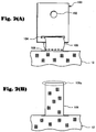
- Fig. 2A and Fig.2B are explanatory views showing a structure of a main portion of a curtain airbag device according to a first example of the invention, wherein the Fig.2A shows a state that a bracket 100 is coupled with a bag body 12, and the Fig.2B shows a state of a tab 106 before the bracket 100 is attached thereto.
- the curtain airbag device according to the example has the bag body 12, a plurality of the tabs 106, and a plurality of the brackets 100.
- the bag body 12 is accommodated to a window upper edge of a vehicle in a compressed state and expanded and inflated toward inside of the vehicle when it is operated, the plurality of tabs 106 are coupled with the bag body 12, and the plurality of brackets 100 fix the bag body 12 to the vehicle.
- the plurality of brackets 100 have slit-shaped coupling holes 104, through which the tabs 106 are inserted, circular fixing holes 102 through which bolts are inserted.
- the bag body 12 is coupled with the brackets 100 by the tabs 106.
- the bag body 12 is fixed to the vehicle by the bolts (not shown) through the brackets 100.
- the strip-shaped tab 106 is formed of the same material as that of the bag body 12 integrally therewith.
- An end portion 106a of the tab 106 is annularly formed passing through the coupling hole 104 of the bracket 100 and is sewed to a portion which is coupled with the bag body 12 or to the other end of the tab 106 itself.
- the bracket 100 is molded of a metal sheet having a strength sufficient to support the bag body 12 that is expanded and inflated.
- the fixing hole 102 has an inside diameter which is necessary for the bolt to pass therethrough.
- the coupling hole 104, through which the tab 106 passes, is formed in a laterally long slit-shape and has a width and a height to allow the tab 106 to easily move therein.
- the curtain airbag device arranged as described above is manufactured (assembled), after the end portions 106a of the tabs 106 are inserted through the coupling holes 104 of the brackets 100, the end portions 106a are sewed to the bag body 12 or to the end portions (roots) of the tabs 106. As a result, the airbag body 12 is coupled with the brackets 100. In this state, the airbag body 12 having the brackets 100 is folded and compressed.
- the airbag device which is folded to a thick rope-shape, is carried to the vicinity of the window upper edge, the bolts (not shown) are inserted into the fixing holes 102 of the brackets 100, and the airbag device is fixed to the vehicle by tightening the bolts.
- brackets 100 are directly tightened and fixed to the vehicle without interposing the bag body (cushion) 12 therebetween, a tightening torque can be suppressed from being reduced as a time passes.
- the brackets 100 can be kept in a free attitude without being restricted by the long and relatively heavy bag body 12. As a result, an attachment job to the vehicle can be easily performed using a tightening tool of a bolt and the like.
- Fig. 3A and Fig.3B are explanatory views showing a structure of a main portion of a curtain airbag device according to a second example of the present invention, wherein Fig.3A shows a state that a bracket 100 is coupled with a bag body 212, and Fig.3B shows a state before the bracket 100 is attached thereto.
- the curtain airbag device according to the second example is different from the airbag device according to the first example described above in that strip-shaped coupling members 206 are composed of members different from the bag body 212. Since the other main arrangements of the second example are similar to those of the first example, an overlapping explanation is omitted.
- each strip-shaped coupling member 206 is composed of the member different from the bag body 212 and has an end portion 206a inserted through a coupling hole 104 of each bracket 100.
- the strip-shaped coupling member 206 is formed in annular shape and sewed to a portion with which the bag body 212 is coupled or to the other end of the strip-shaped coupling member 206 itself.
- a structure of the bracket 100 is similar to that of the first example described above.
- one end of the strip-shaped coupling members 206 are previously sewed to the upper edge portion of the bag body 212.
- the end portions 206a of the strip-shaped coupling members 206 are inserted through the coupling holes 104 of the brackets 100, the end portions 206a are sewed to the bag body 212 or to the end portions (roots) of the strip-shaped coupling members 206.
- the airbag body 212 is coupled with the brackets 100.
- the airbag body 12 having the brackets 100 is folded and compressed. Note that it is also possible to sew and fix both the ends of the strip-shaped coupling members 206 to the bag body 212 at the same time after the strip-shaped coupling members 206 are inserted through the coupling holes 104 of the brackets 100.
- a method of assembling the curtain airbag device according to the second example to a vehicle is also similar to that of the first example described above.
- the strip-shaped coupling member 206 is composed of the different members in the second example, there is an advantage in that a degree of freedom of a coupling job for coupling the brackets 100 to the bag body 212 is increased in addition to the advantage of the first example described above. More specifically, for example, it is possible to perform a sewing job at the same time to a plurality of units, each of which has the strip-shaped coupling member 206 caused to previously pass through the coupling hole 104 of the bracket 100 and which are disposed along the edge portion of the bag body 212.
- the curtain airbag device according to the invention can be applied not only to a passenger car type vehicle but also to various types of vehicles such as one-box type vehicle and the like. Further, although the material of the brackets 10 is the metal in the examples, other material (resin and the like) having a sufficient mechanical strength may be used.
Landscapes
- Engineering & Computer Science (AREA)
- Mechanical Engineering (AREA)
- Air Bags (AREA)
Claims (9)
- Vorhangairbag, umfassend:einen Beutelkörper (12), welcher in einem komprimierten Zustand an einer oberen Fensterkante eines Fahrzeugs angebracht ist, zum Expandieren und Aufblasen in das Innere des Fahrzeugs bei einem Auslösen;eine Mehrzahl von Schellen (100), die mit einem oberen Kantenabschnitt des Beutelkörpers (12) verbunden sind, zum Befestigen des Beutelkörpers an dem Fahrzeug,wobei jede der Mehrzahl von Schellen (100) ein Befestigungsloch (102) aufweist, in welches jedes von vorbestimmten Spannelementen eingeführt wird,wobeider Beutelkörper (12) mit den Schellen (100) durch streifenförmige Verbindungselemente (106, 206) verbunden ist, die mit einem oberen Kantenabschnitt des Beutelkörpers (12) verbunden sind, undjede der Mehrzahl von Schellen (100) ein seitlich langes, schlitzförmiges Verbindungsloch (104) aufweist, durch welches jedes der streifenförmigen Verbindungselemente (106, 206) eingeführt wird, derart, dass ein Endabschnitt (106a) des streifenförmigen Verbindungselements (106, 206) ringförmig ausgebildet ist, wobei dieser durch das Verbindungsloch (104) der Schelle (100) läuft, wobei das Verbindungsloch (104) eine Breite und eine Höhe aufweist, damit sich das streifenförmige Verbindungselement (106, 206) darin leicht bewegen kann, wobei die Breite des Verbindungslochs (104) die Breite des kreisförmigen Verbindungselements (106, 206) überschreitet,derart, dass dann, wenn der Beutelkörper (12) zu der Zeit aufgeblasen wird, wenn der Airbag ausgelöst wird und eine Kraft zum Herunterziehen der Schellen (100) auf die Schellen (100) einwirkt, die Kraft durch die gesamte Breite der streifenförmigen Verbindungselemente (106, 206) gehalten werden kann.
- Vorhangairbag nach Anspruch 1, dadurch gekennzeichnet, dass die streifenförmigen Verbindungselemente (106, 206) einen derartigen Aufbau aufweisen, dass Enden an dem Beutelkörper (12) befestigt sind.
- Vorhangairbag nach Anspruch 2, dadurch gekennzeichnet, dass die Enden der streifenförmigen Verbindungselemente (106, 206) mit dem Beutelkörper (12) durch Nähen verbunden sind.
- Vorhangairbag nach Anspruch 1, 2 oder 3, dadurch gekennzeichnet, dass die streifenförmigen Verbindungselemente (106, 206) Schlaufen (106) sind, die aus dem gleichen Material wie jenes des Beutelkörpers integral damit gebildet sind.
- Vorhangairbag nach Anspruch 1, 2 oder 3, dadurch gekennzeichnet, dass die streifenförmigen Verbindungselemente (206) als Elemente ausgelegt sind, welche sich von dem Beutelkörper unterscheiden.
- Verfahren zum Herstellen des Airbags nach Anspruch 1, dadurch gekennzeichnet, dass es umfasst:einen Schritt eines Verbindens des Airbagkörpers (12) mit den Schellen (100) durch Einführen des einen Endes der streifenförmigen Verbindungselemente (106, 206) durch die Verbindungslöcher (104) der Schellen (100) und dann eines Verbindens beider Enden mit dem Beutelkörper (12); undeinen Schritt eines Faltens und Komprimierens des Airbagskörpers (12) einschließlich der Schellen (100).
- Verfahren zum Herstellen des Vorhangairbags nach Anspruch 6, dadurch gekennzeichnet, dass die Enden der streifenförmigen Verbindungselemente (106, 206) mit dem Beutelkörper (12) durch Nähen verbunden werden.
- Verfahren zum Herstellen des Vorhangairbags nach Anspruch 6 oder 7, dadurch gekennzeichnet, dass die streifenförmigen Verbindungselemente (106, 206) Schlaufen sind, die aus dem gleichen Material wie jenem des Beutelkörpers (12) integral damit gebildet werden.
- Verfahren zum Herstellen des Vorhangairbags nach Anspruch 6 oder 7, dadurch gekennzeichnet, dass die streifenförmigen Verbindungselemente als Elemente unterschiedlich von dem Beutelkörper ausgelegt werden.
Applications Claiming Priority (2)
| Application Number | Priority Date | Filing Date | Title |
|---|---|---|---|
| JP2007127526 | 2007-05-14 | ||
| PCT/JP2008/001209 WO2008139737A1 (ja) | 2007-05-14 | 2008-05-14 | カーテンエアバッグ装置及びその製造方法 |
Publications (3)
| Publication Number | Publication Date |
|---|---|
| EP2156993A1 EP2156993A1 (de) | 2010-02-24 |
| EP2156993A4 EP2156993A4 (de) | 2013-04-24 |
| EP2156993B1 true EP2156993B1 (de) | 2017-05-10 |
Family
ID=40001962
Family Applications (1)
| Application Number | Title | Priority Date | Filing Date |
|---|---|---|---|
| EP08751727.2A Active EP2156993B1 (de) | 2007-05-14 | 2008-05-14 | Vorhangairbag und verfahren zu seiner herstellung |
Country Status (4)
| Country | Link |
|---|---|
| US (1) | US8562016B2 (de) |
| EP (1) | EP2156993B1 (de) |
| JP (1) | JP5037611B2 (de) |
| WO (1) | WO2008139737A1 (de) |
Families Citing this family (15)
| Publication number | Priority date | Publication date | Assignee | Title |
|---|---|---|---|---|
| JP5024956B2 (ja) * | 2007-06-28 | 2012-09-12 | 日本プラスト株式会社 | エアバッグ用取付具及びエアバッグ装置 |
| JP4852510B2 (ja) * | 2007-10-04 | 2012-01-11 | 本田技研工業株式会社 | エアバッグ取付金具 |
| DE102008061282B4 (de) * | 2008-12-11 | 2021-03-04 | Autoliv Development Ab | Vorhanggassack für ein Kraftfahrzeug und Beschlagteil zur Befestigung eines Vorhanggassackes an einem Kraftfahrzeug |
| DE102010049112B4 (de) * | 2010-10-22 | 2015-07-30 | Autoliv Development Ab | Beschlagteil zur Befestigung eines Spannbandes eines Vorhanggassackes an einem Fahrzeugteil |
| JP6101555B2 (ja) * | 2013-05-07 | 2017-03-22 | オートリブ ディベロップメント エービー | カーテンエアバッグ |
| KR102439459B1 (ko) * | 2015-09-11 | 2022-09-02 | 현대모비스 주식회사 | 루프 에어백장치 |
| JP6817296B2 (ja) * | 2015-10-07 | 2021-01-20 | キー セーフティー システムズ、 インコーポレイテッドKey Safety Systems, Inc. | サイドカーテンエアバッグモジュール |
| US9981625B2 (en) * | 2016-02-25 | 2018-05-29 | Autoliv Asp, Inc. | Airbag mounting bracket |
| DE102016120177A1 (de) * | 2016-10-24 | 2018-04-26 | Trw Automotive Gmbh | Gassackmodul |
| DE102017101092A1 (de) * | 2017-01-20 | 2018-07-26 | Trw Automotive Gmbh | Verfahren zum Zusammenlegen eines Gassacks |
| KR102475714B1 (ko) * | 2017-10-13 | 2022-12-09 | 현대모비스 주식회사 | 루프 에어백 장치 |
| US11260821B2 (en) * | 2019-07-11 | 2022-03-01 | ZF Passive Safety Systems US Inc. | Airbag mounting tab assembly |
| CN212604972U (zh) * | 2020-06-19 | 2021-02-26 | 奥托立夫开发公司 | 用于安全气囊的吊耳和安全气囊 |
| US11345302B2 (en) * | 2020-07-27 | 2022-05-31 | ZF Passive Safety Systems US Inc. | Curtain airbag with integral airbag wrap |
| KR20220158440A (ko) * | 2021-05-24 | 2022-12-01 | 현대모비스 주식회사 | 커튼에어백용 차체 결합 장치 |
Family Cites Families (22)
| Publication number | Priority date | Publication date | Assignee | Title |
|---|---|---|---|---|
| JP3444789B2 (ja) * | 1998-07-16 | 2003-09-08 | トヨタ自動車株式会社 | 頭部保護エアバッグ袋体の固定構造 |
| JP2000033846A (ja) * | 1998-07-17 | 2000-02-02 | Toyota Motor Corp | 頭部保護エアバッグ装置 |
| JP3716646B2 (ja) * | 1998-11-05 | 2005-11-16 | タカタ株式会社 | 布シート及びその車体への取付構造 |
| JP4278261B2 (ja) | 2000-02-10 | 2009-06-10 | 株式会社イノアックコーポレーション | カーテンエアバッグ付き車両のクォータウィンドガーニッシュ部の構造 |
| DE20014568U1 (de) * | 2000-08-23 | 2001-01-04 | Trw Repa Gmbh | Befestigungsvorrichtung |
| JP4743807B2 (ja) | 2000-12-20 | 2011-08-10 | タカタ株式会社 | カーテンエアバッグ |
| DE10148216A1 (de) * | 2001-09-28 | 2002-12-12 | Daimler Chrysler Ag | Befestigungselement |
| JP4106546B2 (ja) * | 2002-12-27 | 2008-06-25 | 日本プラスト株式会社 | カーテンエアバッグ |
| US6991256B2 (en) * | 2003-01-30 | 2006-01-31 | Autoliv Asp, Inc. | Quick connect cushion mounting system |
| JP2005096697A (ja) * | 2003-09-26 | 2005-04-14 | Toyoda Gosei Co Ltd | 頭部保護エアバッグ装置 |
| JP2005104234A (ja) * | 2003-09-29 | 2005-04-21 | Nippon Plast Co Ltd | エアバッグ装置 |
| US7125037B2 (en) * | 2003-10-21 | 2006-10-24 | Autoliv Asp, Inc. | Inflatable cushion retention system |
| US7083188B2 (en) * | 2003-11-13 | 2006-08-01 | Autoliv Asp, Inc. | Tearable retention apparatus and method for an airbag cushion |
| DE102004007415B4 (de) * | 2004-02-16 | 2006-02-09 | Key Safety Systems, Inc.(n.d.Ges.d.Staates Delaware), Sterling Heights | Befestigung für einen Gassack |
| US7172212B2 (en) * | 2004-09-22 | 2007-02-06 | Honda Motor Co., Ltd. | Vehicle occupant protection device |
| US7357408B2 (en) * | 2005-02-28 | 2008-04-15 | Autoliv Asp, Inc. | Inflatable curtain cushion tab shock absorption |
| EP1721788B1 (de) * | 2005-04-22 | 2011-08-24 | Lisi Automotive Rapid | Befestigungselement zum Anbringen und Rückhalten eines Airbags an einer Fahrzeugkarosserie |
| US7547038B2 (en) * | 2005-07-28 | 2009-06-16 | Autoliv Asp, Inc. | Inflatable curtain with multi-layered tab |
| EP1837252A1 (de) * | 2006-03-14 | 2007-09-26 | Delphi Korea Corporation | Halterung zum Sichern von seitlichen Airbags für Kraftfahrzeuge |
| US7823914B2 (en) * | 2007-05-14 | 2010-11-02 | Autoliv Asp, Inc. | Airbag mounting assembly and method of manufacture |
| JP2009262673A (ja) * | 2008-04-23 | 2009-11-12 | Takata Corp | カーテンエアバッグ用ブラケット及びカーテンエアバッグ装置 |
| JP2009292441A (ja) * | 2008-06-09 | 2009-12-17 | Takata Corp | カーテンエアバッグ用ブラケット及びカーテンエアバッグ装置 |
-
2008
- 2008-05-14 EP EP08751727.2A patent/EP2156993B1/de active Active
- 2008-05-14 WO PCT/JP2008/001209 patent/WO2008139737A1/ja active Application Filing
- 2008-05-14 US US12/600,155 patent/US8562016B2/en active Active
- 2008-05-14 JP JP2009514019A patent/JP5037611B2/ja active Active
Also Published As
| Publication number | Publication date |
|---|---|
| US8562016B2 (en) | 2013-10-22 |
| US20110215556A1 (en) | 2011-09-08 |
| WO2008139737A1 (ja) | 2008-11-20 |
| JP5037611B2 (ja) | 2012-10-03 |
| EP2156993A4 (de) | 2013-04-24 |
| JPWO2008139737A1 (ja) | 2010-07-29 |
| EP2156993A1 (de) | 2010-02-24 |
Similar Documents
| Publication | Publication Date | Title |
|---|---|---|
| EP2156993B1 (de) | Vorhangairbag und verfahren zu seiner herstellung | |
| EP1948483B1 (de) | Flexibles gehäuse für ein airbag-modul | |
| US6588793B2 (en) | Thin airbag module design for overhead applications | |
| US7125037B2 (en) | Inflatable cushion retention system | |
| US7896387B2 (en) | Air bag device for automobile | |
| EP1899199B1 (de) | Flexibles gehäuse für ein airbag-modul | |
| US9573550B1 (en) | Side curtain airbag compression inflator bracket | |
| US7654559B2 (en) | Airbag apparatus | |
| JPH1191489A (ja) | 頭部保護エアバッグ袋体を搭載した車両の内装品取付構造 | |
| US7896388B2 (en) | Seat airbag | |
| JPH11129857A (ja) | 頭部保護エアバッグ装置 | |
| US6616178B1 (en) | Head protective bag | |
| JP4609998B2 (ja) | エアバッグ装置 | |
| JP2004210099A (ja) | カーテンエアバッグとその組立体 | |
| EP2692590B1 (de) | Airbagvorrichtung | |
| JP2005104234A (ja) | エアバッグ装置 | |
| EP2703233B1 (de) | Airbagvorrichtung | |
| JP2009078717A (ja) | エアバッグ装置 | |
| JP3234564B2 (ja) | 頭部保護エアバッグ装置の組付方法 | |
| US11833991B2 (en) | Fixing apparatus for curtain airbag cushion and curtain airbag having the same | |
| JP3464858B2 (ja) | エアバッグ装置のカバー体 | |
| JP2002362283A (ja) | グラブレールの取付構造 | |
| JP5627398B2 (ja) | カーテンエアバッグ | |
| JP2006298286A (ja) | カーテンエアバッグ装置 | |
| JPH11301400A (ja) | 頭部保護エアバッグ装置の配設構造 |
Legal Events
| Date | Code | Title | Description |
|---|---|---|---|
| PUAI | Public reference made under article 153(3) epc to a published international application that has entered the european phase |
Free format text: ORIGINAL CODE: 0009012 |
|
| 17P | Request for examination filed |
Effective date: 20091109 |
|
| AK | Designated contracting states |
Kind code of ref document: A1 Designated state(s): AT BE BG CH CY CZ DE DK EE ES FI FR GB GR HR HU IE IS IT LI LT LU LV MC MT NL NO PL PT RO SE SI SK TR |
|
| AX | Request for extension of the european patent |
Extension state: AL BA MK RS |
|
| DAX | Request for extension of the european patent (deleted) | ||
| REG | Reference to a national code |
Ref country code: DE Ref legal event code: R079 Ref document number: 602008050219 Country of ref document: DE Free format text: PREVIOUS MAIN CLASS: B60R0021200000 Ipc: B60R0021213000 |
|
| A4 | Supplementary search report drawn up and despatched |
Effective date: 20130322 |
|
| RIC1 | Information provided on ipc code assigned before grant |
Ipc: B60R 21/213 20110101AFI20130318BHEP |
|
| 17Q | First examination report despatched |
Effective date: 20130408 |
|
| GRAP | Despatch of communication of intention to grant a patent |
Free format text: ORIGINAL CODE: EPIDOSNIGR1 |
|
| STAA | Information on the status of an ep patent application or granted ep patent |
Free format text: STATUS: GRANT OF PATENT IS INTENDED |
|
| INTG | Intention to grant announced |
Effective date: 20161128 |
|
| RIN1 | Information on inventor provided before grant (corrected) |
Inventor name: SAEGUSA, TAKAYOSHI Inventor name: HIGANO, MAKOTO |
|
| GRAS | Grant fee paid |
Free format text: ORIGINAL CODE: EPIDOSNIGR3 |
|
| GRAA | (expected) grant |
Free format text: ORIGINAL CODE: 0009210 |
|
| STAA | Information on the status of an ep patent application or granted ep patent |
Free format text: STATUS: THE PATENT HAS BEEN GRANTED |
|
| AK | Designated contracting states |
Kind code of ref document: B1 Designated state(s): AT BE BG CH CY CZ DE DK EE ES FI FR GB GR HR HU IE IS IT LI LT LU LV MC MT NL NO PL PT RO SE SI SK TR |
|
| REG | Reference to a national code |
Ref country code: GB Ref legal event code: FG4D |
|
| REG | Reference to a national code |
Ref country code: AT Ref legal event code: REF Ref document number: 891959 Country of ref document: AT Kind code of ref document: T Effective date: 20170515 Ref country code: CH Ref legal event code: EP |
|
| REG | Reference to a national code |
Ref country code: FR Ref legal event code: PLFP Year of fee payment: 10 |
|
| REG | Reference to a national code |
Ref country code: IE Ref legal event code: FG4D |
|
| REG | Reference to a national code |
Ref country code: DE Ref legal event code: R096 Ref document number: 602008050219 Country of ref document: DE |
|
| REG | Reference to a national code |
Ref country code: NL Ref legal event code: MP Effective date: 20170510 |
|
| REG | Reference to a national code |
Ref country code: LT Ref legal event code: MG4D |
|
| REG | Reference to a national code |
Ref country code: AT Ref legal event code: MK05 Ref document number: 891959 Country of ref document: AT Kind code of ref document: T Effective date: 20170510 |
|
| PG25 | Lapsed in a contracting state [announced via postgrant information from national office to epo] |
Ref country code: AT Free format text: LAPSE BECAUSE OF FAILURE TO SUBMIT A TRANSLATION OF THE DESCRIPTION OR TO PAY THE FEE WITHIN THE PRESCRIBED TIME-LIMIT Effective date: 20170510 Ref country code: HR Free format text: LAPSE BECAUSE OF FAILURE TO SUBMIT A TRANSLATION OF THE DESCRIPTION OR TO PAY THE FEE WITHIN THE PRESCRIBED TIME-LIMIT Effective date: 20170510 Ref country code: GR Free format text: LAPSE BECAUSE OF FAILURE TO SUBMIT A TRANSLATION OF THE DESCRIPTION OR TO PAY THE FEE WITHIN THE PRESCRIBED TIME-LIMIT Effective date: 20170811 Ref country code: ES Free format text: LAPSE BECAUSE OF FAILURE TO SUBMIT A TRANSLATION OF THE DESCRIPTION OR TO PAY THE FEE WITHIN THE PRESCRIBED TIME-LIMIT Effective date: 20170510 Ref country code: LT Free format text: LAPSE BECAUSE OF FAILURE TO SUBMIT A TRANSLATION OF THE DESCRIPTION OR TO PAY THE FEE WITHIN THE PRESCRIBED TIME-LIMIT Effective date: 20170510 Ref country code: NO Free format text: LAPSE BECAUSE OF FAILURE TO SUBMIT A TRANSLATION OF THE DESCRIPTION OR TO PAY THE FEE WITHIN THE PRESCRIBED TIME-LIMIT Effective date: 20170810 Ref country code: FI Free format text: LAPSE BECAUSE OF FAILURE TO SUBMIT A TRANSLATION OF THE DESCRIPTION OR TO PAY THE FEE WITHIN THE PRESCRIBED TIME-LIMIT Effective date: 20170510 |
|
| PG25 | Lapsed in a contracting state [announced via postgrant information from national office to epo] |
Ref country code: NL Free format text: LAPSE BECAUSE OF FAILURE TO SUBMIT A TRANSLATION OF THE DESCRIPTION OR TO PAY THE FEE WITHIN THE PRESCRIBED TIME-LIMIT Effective date: 20170510 Ref country code: PL Free format text: LAPSE BECAUSE OF FAILURE TO SUBMIT A TRANSLATION OF THE DESCRIPTION OR TO PAY THE FEE WITHIN THE PRESCRIBED TIME-LIMIT Effective date: 20170510 Ref country code: IS Free format text: LAPSE BECAUSE OF FAILURE TO SUBMIT A TRANSLATION OF THE DESCRIPTION OR TO PAY THE FEE WITHIN THE PRESCRIBED TIME-LIMIT Effective date: 20170910 Ref country code: SE Free format text: LAPSE BECAUSE OF FAILURE TO SUBMIT A TRANSLATION OF THE DESCRIPTION OR TO PAY THE FEE WITHIN THE PRESCRIBED TIME-LIMIT Effective date: 20170510 Ref country code: BG Free format text: LAPSE BECAUSE OF FAILURE TO SUBMIT A TRANSLATION OF THE DESCRIPTION OR TO PAY THE FEE WITHIN THE PRESCRIBED TIME-LIMIT Effective date: 20170810 Ref country code: LV Free format text: LAPSE BECAUSE OF FAILURE TO SUBMIT A TRANSLATION OF THE DESCRIPTION OR TO PAY THE FEE WITHIN THE PRESCRIBED TIME-LIMIT Effective date: 20170510 |
|
| REG | Reference to a national code |
Ref country code: CH Ref legal event code: PL |
|
| PG25 | Lapsed in a contracting state [announced via postgrant information from national office to epo] |
Ref country code: DK Free format text: LAPSE BECAUSE OF FAILURE TO SUBMIT A TRANSLATION OF THE DESCRIPTION OR TO PAY THE FEE WITHIN THE PRESCRIBED TIME-LIMIT Effective date: 20170510 Ref country code: EE Free format text: LAPSE BECAUSE OF FAILURE TO SUBMIT A TRANSLATION OF THE DESCRIPTION OR TO PAY THE FEE WITHIN THE PRESCRIBED TIME-LIMIT Effective date: 20170510 Ref country code: RO Free format text: LAPSE BECAUSE OF FAILURE TO SUBMIT A TRANSLATION OF THE DESCRIPTION OR TO PAY THE FEE WITHIN THE PRESCRIBED TIME-LIMIT Effective date: 20170510 Ref country code: CZ Free format text: LAPSE BECAUSE OF FAILURE TO SUBMIT A TRANSLATION OF THE DESCRIPTION OR TO PAY THE FEE WITHIN THE PRESCRIBED TIME-LIMIT Effective date: 20170510 Ref country code: SK Free format text: LAPSE BECAUSE OF FAILURE TO SUBMIT A TRANSLATION OF THE DESCRIPTION OR TO PAY THE FEE WITHIN THE PRESCRIBED TIME-LIMIT Effective date: 20170510 |
|
| REG | Reference to a national code |
Ref country code: DE Ref legal event code: R097 Ref document number: 602008050219 Country of ref document: DE |
|
| REG | Reference to a national code |
Ref country code: IE Ref legal event code: MM4A |
|
| PG25 | Lapsed in a contracting state [announced via postgrant information from national office to epo] |
Ref country code: CH Free format text: LAPSE BECAUSE OF NON-PAYMENT OF DUE FEES Effective date: 20170531 Ref country code: IT Free format text: LAPSE BECAUSE OF FAILURE TO SUBMIT A TRANSLATION OF THE DESCRIPTION OR TO PAY THE FEE WITHIN THE PRESCRIBED TIME-LIMIT Effective date: 20170510 Ref country code: LI Free format text: LAPSE BECAUSE OF NON-PAYMENT OF DUE FEES Effective date: 20170531 |
|
| PLBE | No opposition filed within time limit |
Free format text: ORIGINAL CODE: 0009261 |
|
| STAA | Information on the status of an ep patent application or granted ep patent |
Free format text: STATUS: NO OPPOSITION FILED WITHIN TIME LIMIT |
|
| PG25 | Lapsed in a contracting state [announced via postgrant information from national office to epo] |
Ref country code: LU Free format text: LAPSE BECAUSE OF NON-PAYMENT OF DUE FEES Effective date: 20170514 |
|
| 26N | No opposition filed |
Effective date: 20180213 |
|
| REG | Reference to a national code |
Ref country code: BE Ref legal event code: MM Effective date: 20170531 |
|
| PG25 | Lapsed in a contracting state [announced via postgrant information from national office to epo] |
Ref country code: IE Free format text: LAPSE BECAUSE OF NON-PAYMENT OF DUE FEES Effective date: 20170514 |
|
| REG | Reference to a national code |
Ref country code: FR Ref legal event code: PLFP Year of fee payment: 11 |
|
| PG25 | Lapsed in a contracting state [announced via postgrant information from national office to epo] |
Ref country code: SI Free format text: LAPSE BECAUSE OF FAILURE TO SUBMIT A TRANSLATION OF THE DESCRIPTION OR TO PAY THE FEE WITHIN THE PRESCRIBED TIME-LIMIT Effective date: 20170510 |
|
| PG25 | Lapsed in a contracting state [announced via postgrant information from national office to epo] |
Ref country code: BE Free format text: LAPSE BECAUSE OF NON-PAYMENT OF DUE FEES Effective date: 20170531 |
|
| PG25 | Lapsed in a contracting state [announced via postgrant information from national office to epo] |
Ref country code: MT Free format text: LAPSE BECAUSE OF NON-PAYMENT OF DUE FEES Effective date: 20170514 |
|
| PG25 | Lapsed in a contracting state [announced via postgrant information from national office to epo] |
Ref country code: HU Free format text: LAPSE BECAUSE OF FAILURE TO SUBMIT A TRANSLATION OF THE DESCRIPTION OR TO PAY THE FEE WITHIN THE PRESCRIBED TIME-LIMIT; INVALID AB INITIO Effective date: 20080514 Ref country code: MC Free format text: LAPSE BECAUSE OF FAILURE TO SUBMIT A TRANSLATION OF THE DESCRIPTION OR TO PAY THE FEE WITHIN THE PRESCRIBED TIME-LIMIT Effective date: 20170510 |
|
| PG25 | Lapsed in a contracting state [announced via postgrant information from national office to epo] |
Ref country code: CY Free format text: LAPSE BECAUSE OF NON-PAYMENT OF DUE FEES Effective date: 20170510 |
|
| PGFP | Annual fee paid to national office [announced via postgrant information from national office to epo] |
Ref country code: GB Payment date: 20190530 Year of fee payment: 12 |
|
| PG25 | Lapsed in a contracting state [announced via postgrant information from national office to epo] |
Ref country code: TR Free format text: LAPSE BECAUSE OF FAILURE TO SUBMIT A TRANSLATION OF THE DESCRIPTION OR TO PAY THE FEE WITHIN THE PRESCRIBED TIME-LIMIT Effective date: 20170510 |
|
| PG25 | Lapsed in a contracting state [announced via postgrant information from national office to epo] |
Ref country code: PT Free format text: LAPSE BECAUSE OF FAILURE TO SUBMIT A TRANSLATION OF THE DESCRIPTION OR TO PAY THE FEE WITHIN THE PRESCRIBED TIME-LIMIT Effective date: 20170510 |
|
| GBPC | Gb: european patent ceased through non-payment of renewal fee |
Effective date: 20200514 |
|
| PG25 | Lapsed in a contracting state [announced via postgrant information from national office to epo] |
Ref country code: GB Free format text: LAPSE BECAUSE OF NON-PAYMENT OF DUE FEES Effective date: 20200514 |
|
| P01 | Opt-out of the competence of the unified patent court (upc) registered |
Effective date: 20230507 |
|
| PGFP | Annual fee paid to national office [announced via postgrant information from national office to epo] |
Ref country code: FR Payment date: 20230519 Year of fee payment: 16 Ref country code: DE Payment date: 20230519 Year of fee payment: 16 |