EP2151192B1 - X-ray imaging apparatus - Google Patents
X-ray imaging apparatus Download PDFInfo
- Publication number
- EP2151192B1 EP2151192B1 EP09167185.9A EP09167185A EP2151192B1 EP 2151192 B1 EP2151192 B1 EP 2151192B1 EP 09167185 A EP09167185 A EP 09167185A EP 2151192 B1 EP2151192 B1 EP 2151192B1
- Authority
- EP
- European Patent Office
- Prior art keywords
- image
- ray imaging
- ray
- connection
- drive
- Prior art date
- Legal status (The legal status is an assumption and is not a legal conclusion. Google has not performed a legal analysis and makes no representation as to the accuracy of the status listed.)
- Not-in-force
Links
- 238000003384 imaging method Methods 0.000 title claims description 187
- 238000000034 method Methods 0.000 claims description 104
- 238000009825 accumulation Methods 0.000 claims description 78
- 238000004891 communication Methods 0.000 claims description 50
- 230000008859 change Effects 0.000 claims description 23
- 238000003672 processing method Methods 0.000 claims description 15
- 238000012937 correction Methods 0.000 claims description 13
- 230000009467 reduction Effects 0.000 claims description 13
- 230000005540 biological transmission Effects 0.000 claims description 3
- 230000005855 radiation Effects 0.000 description 40
- 238000012545 processing Methods 0.000 description 26
- 230000006870 function Effects 0.000 description 16
- 238000006243 chemical reaction Methods 0.000 description 15
- 238000007781 pre-processing Methods 0.000 description 14
- 230000008569 process Effects 0.000 description 10
- 230000015654 memory Effects 0.000 description 8
- 238000010586 diagram Methods 0.000 description 7
- 238000002360 preparation method Methods 0.000 description 4
- 210000000746 body region Anatomy 0.000 description 3
- 210000000038 chest Anatomy 0.000 description 3
- 210000004394 hip joint Anatomy 0.000 description 3
- 210000001694 thigh bone Anatomy 0.000 description 3
- 238000004590 computer program Methods 0.000 description 2
- 238000000354 decomposition reaction Methods 0.000 description 2
- 230000003111 delayed effect Effects 0.000 description 2
- 230000036541 health Effects 0.000 description 2
- 230000004044 response Effects 0.000 description 2
- 210000000115 thoracic cavity Anatomy 0.000 description 2
- 238000012546 transfer Methods 0.000 description 2
- 230000002411 adverse Effects 0.000 description 1
- 230000015556 catabolic process Effects 0.000 description 1
- 238000006731 degradation reaction Methods 0.000 description 1
- 238000003745 diagnosis Methods 0.000 description 1
- 230000001771 impaired effect Effects 0.000 description 1
- 230000003287 optical effect Effects 0.000 description 1
- 230000035945 sensitivity Effects 0.000 description 1
- 230000004936 stimulating effect Effects 0.000 description 1
- 239000000758 substrate Substances 0.000 description 1
- 238000002834 transmittance Methods 0.000 description 1
- 230000003313 weakening effect Effects 0.000 description 1
- 230000003936 working memory Effects 0.000 description 1
Images


Classifications
-
- A—HUMAN NECESSITIES
- A61—MEDICAL OR VETERINARY SCIENCE; HYGIENE
- A61B—DIAGNOSIS; SURGERY; IDENTIFICATION
- A61B6/00—Apparatus or devices for radiation diagnosis; Apparatus or devices for radiation diagnosis combined with radiation therapy equipment
- A61B6/56—Details of data transmission or power supply, e.g. use of slip rings
-
- H—ELECTRICITY
- H04—ELECTRIC COMMUNICATION TECHNIQUE
- H04L—TRANSMISSION OF DIGITAL INFORMATION, e.g. TELEGRAPHIC COMMUNICATION
- H04L67/00—Network arrangements or protocols for supporting network services or applications
- H04L67/01—Protocols
- H04L67/12—Protocols specially adapted for proprietary or special-purpose networking environments, e.g. medical networks, sensor networks, networks in vehicles or remote metering networks
Definitions
- the present invention relates to X-ray imaging apparatuses capable of capturing an X-ray image of a subject.
- X-ray imaging for medical diagnostic purposes, digital imaging apparatuses in which an imaging unit including a photoelectric conversion element performs imaging have been widely used in recent years.
- Such a digital imaging apparatus is capable of producing an X-ray image without developing a film etc., and thus is advantageous in terms of immediacy over an imaging apparatus using a film.
- an imaging unit and an X-ray generating unit are connected to each other via a dedicated line. This allows communication of drive timing signals and timing signals for X-ray generation, as well as power and image information, between the imaging unit and the X-ray generating unit.
- an X-ray imaging apparatus having an imaging unit including a photoelectric conversion element, after X-ray radiation, electrons converted by X-rays are read from the photoelectric conversion element. Thus, an image representing a distribution of transmittance of x-rays radiated during a specific period of time is produced.
- an X-ray generating unit transmits readout timing to an X-ray imaging unit for synchronization therebetween. Specifically, after completion of X-ray radiation, the X-ray generating unit transmits an X-ray radiation completion signal to the X-ray imaging unit. Upon receipt of the X-ray radiation completion signal, the X-ray imaging unit terminates accumulation of electric charge and starts reading out electrons.
- an X-ray generating unit radiates X-rays during a period of time in which it is permitted to radiate X-rays. Then, after receipt of an X-ray generation signal, an X-ray imaging unit reads out an image during a fixed period of image accumulation time.
- the X-ray generating unit and the X-ray imaging unit in response to instructions from a first switch to prepare for X-ray imaging, start preparing for imaging. Then, accumulation of electric charge is started.
- a time delay may occur depending on the method for connection between the X-ray generating unit and the X-ray imaging unit.
- a connection between an X-ray imaging unit and an X-ray generating unit can be made via a general-purpose line or a wireless connection, as well as via a dedicated line.
- a connection using a general-purpose line or a wireless connection is advantageous over a connection using a dedicated line, in terms of usability and cost.
- general-purpose lines include Ethernet (registered trademark) and Gigabit Ethernet (registered trademark).
- wireless connections include a wireless local area network (LAN) connection and a connection which allows communication using low and high frequency electromagnetic waves, such as those used in dedicated short-range communication.
- connection method other than that using a dedicated line that is, for example, when a wireless connection is used
- external factors including transmissibility of electromagnetic waves may prevent the connection from being established at one time.
- many retries for the connection may cause a time delay.
- line congestion may reduce communication speed and may also cause a time delay.
- Reasons for using a connection method other than a dedicated wired connection that is, reasons for using a wireless connection or the like are that digital X-ray imaging apparatuses are demanded to achieve improved usability and reduced cost, as well as high-quality images.
- a known X-ray imaging apparatus having a fix period of accumulation time, there may be a period of time in which signals cannot be accumulated during X-ray radiation. That is, there may be a period of time in which unnecessary x-ray radiation takes place. In other words, the known X-ray imaging apparatus does not optimize the timing control of imaging drive signals in accordance with different conditions.
- Japanese Patent Laid-Open No. 2005-46203 discloses a control method for controlling an X-ray imaging operation performed by the X-ray generating unit and the X-ray imaging unit.
- the X-ray generating unit generates X-rays, while the X-ray imaging unit accumulates electric charge corresponding to the amount of the X-rays and outputs an electric signal.
- This control method causes the X-ray generating unit to prepare for X-ray generation in accordance with an instruction to prepare for X-ray imaging.
- the control method includes the steps of starting accumulation of electric charge after the X-ray imaging unit completes preparation for X-ray imaging, generating X-rays in accordance with an instruction to perform X-ray imaging, and terminating the accumulation of electric charge and the generation of X-rays when a predetermined period of time has elapsed since the start of accumulation of electric charge.
- Japanese Patent Laid-Open No. 2005-46203 does not provide a means for changing the time for terminating the accumulation of electric charge depending on the connection method, accumulation time, and information about a region whose image is to be captured.
- An X-ray imaging apparatus disclosed in Japanese Patent No. 3105520 includes an image recording device and a synchronizing device.
- the image recording device applies a recording pulse to the synchronizing device, which adjusts synchronization of an X-ray source to changes in periodical operation.
- the X-ray imaging apparatus transmits an imaging drive signal for synchronization of the X-ray source.
- the drive method such as timing of the imaging drive signal, depending on the connection method etc.
- Japanese Patent Laid-Open No. 2001-276032 discloses an imaging apparatus that has a configuration for preventing degradation of image quality caused by vibrations and electromagnetic noise resulting from grid movement. With this configuration, the imaging apparatus is capable of capturing high-quality images most suitable for medical diagnosis. In this imaging apparatus, after a drive operation for driving the movement of a movable grid is stopped, a readout operation for reading out an accumulation signal of an image pickup element is started.
- a radiation imaging apparatus disclosed in Japanese Patent Laid-Open No. 2005-312949 includes a conversion circuit unit in which a plurality of pixels including conversion elements are arranged in an array on a substrate, a readout circuit unit configured to read out a signal from the conversion circuit unit, and a radiation generation switch used to instruct a radiation generating unit to emit radiation.
- An imaging operation period for capturing a radiation image includes two operation periods: an idling operation period before emission of radiation, and a reading operation period starting at the time of emission of radiation. To enable the operator to operate the radiation generation switch at appropriate time immediately after the end of the idling operation period, the radiation imaging apparatus generates an emission stimulating signal to the operator during the idling operation period.
- the radiation imaging apparatus disclosed in Japanese Patent Laid-Open No. 2005-312949 has no means to change the drive method, such as accumulation time, depending on the connection method etc.
- an X-ray imaging apparatus including a photoelectric conversion element performs communication using a connection method other than a connection method using a dedicated line, synchronization with an X-ray generating unit may be lost or radiation may take place during a period of time in which image accumulation is not performed.
- the above problems may be solved by significantly increasing the image accumulation time.
- dark current noise of a photoelectric conversion element increases and, as a result, image quality may be adversely affected.
- US-A-2004/0114725 discloses an X-ray imaging apparatus and method of use thereof as claimed in the precharacterizing portion of the independent claims herein.
- the present invention provides an X-ray imaging apparatus and method capable of solving the problems described above. That is, the present invention provides an X-ray imaging apparatus and method capable of preventing unnecessary X-ray radiation caused by communication delay depending on the communication method, while reducing image accumulation time in an imaging unit.
- an X-ray imaging method as specified in claim 10.
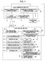
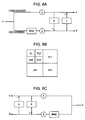
- Fig. 1 is a block diagram illustrating a circuit configuration of an X-ray imaging apparatus according to a first exemplary embodiment of the present invention.
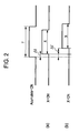
- Fig. 2 is a timing diagram of a known X-ray imaging apparatus.
- Fig. 3 is a timing diagram of the X-ray imaging apparatus according to the first exemplary embodiment.
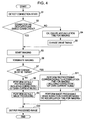
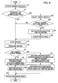
- Fig. 4 is a flowchart of a method of operation of the first exemplary embodiment.
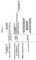
- Fig. 5 illustrates a sequence in the X-ray imaging apparatus of the first exemplary embodiment.
- Fig. 6 illustrates a sequence in a known X-ray imaging apparatus.
- Fig. 7 is a front view of an operation panel.
- Fig. 8A to Fig. 8C illustrate discrete wavelet transform and inverse transform for noise reduction.
- Fig. 9 is a flowchart of a method of operation of a second exemplary embodiment of the present invention.
- Fig. 10 is a perspective view of examples of imaging systems to which an X-ray imaging apparatus can be attached.
- Fig. 1 is a block diagram illustrating a circuit configuration of an entire X-ray imaging apparatus according to a first exemplary embodiment of the present invention.
- the X-ray imaging apparatus includes an X-ray generating section 1 that generates X-rays, and an X-ray imaging section 10 on which X-rays having passed through a subject P is incident.
- the X-ray generating section 1 and the X-ray imaging section 10 are arranged opposite each other.
- the X-ray generating section 1 includes an X-ray generating unit 2 that generates X-rays.
- the X-ray generating unit 2 is connected to an X-ray generation control unit 3.
- a plurality of communication connection units that is, a wireless communication connection unit 5 for wireless communication with the X-ray imaging section 10 and a wired communication connection unit 6 for wired communication with the X-ray imaging section 10 are connected to the X-ray generation control unit 3 via a bus 4.
- An operation unit 7 for operating the X-ray generating section 1 via the bus 4 is connected to the X-ray generating section 1.
- the X-ray imaging section 10 includes a two-dimensional X-ray imaging unit 11 including a photoelectric conversion element that receives X-rays having passed through the subject P.
- the two-dimensional X-ray imaging unit 11 is connected through a central processing unit (CPU) bus 12 to an analog-to-digital (A/D) conversion unit 13, an amplifying unit 14, a data collecting unit 15 that collects captured image data, and a preprocessing unit 16 that preprocesses an image obtained by the data collecting unit 15.
- CPU central processing unit
- A/D analog-to-digital
- An image processing unit 17, a storage unit 18 that stores an image, a CPU 19, a main memory 20, an operation panel 21, an image display unit 22, a drive-method changing unit 23, a drive-method-table switching determining unit 24, and a target-region selecting unit 25 are connected to the CPU bus 12.
- a plurality of communication connection units that is, a wireless communication connection unit 26 and a wired communication connection unit 27 for communicating with the X-ray generating section 1 are also connected to the CPU bus 12.
- the main memory 20 stores various types of data necessary for processing in the CPU 19. At the same time, the main memory 20 functions as a working memory for the CPU 19.
- the CPU 19 uses the main memory 20 to control an overall operation of the X-ray imaging apparatus in accordance with an operation on the operation panel 21.
- the X-ray imaging section 10 communicates through the wireless communication connection unit 26 or the wired communication connection unit 27 with the wireless communication connection unit 5 or the wired communication connection unit 6 in the X-ray generating section 1, for example, every 10 minutes.
- the X-ray imaging section 10 indicates, on the operation panel 21, a communication connection unit used to perform imaging.
- the imaging instructions are displayed on the operation panel 21 as well as being stored in the storage unit 18.
- the operator uses the target-region selecting unit 25 on the operation panel 21 to select a specific region whose image is to be captured (hereinafter referred to as "target region").
- the imaging instructions are transmitted by the CPU 19 via the CPU bus 12 to the drive-method changing unit 23.
- the drive-method changing unit 23 changes a drive method through the drive-method-table switching determining unit 24.
- the X-ray generating section 1 controls the X-ray generating unit 2 through the X-ray generation control unit 3 to perform X-ray imaging by radiating X-rays.
- X-rays radiated from the X-ray generating unit 2 pass through the subject P while attenuating, and reach the two-dimensional X-ray imaging unit 11. Then, the two-dimensional X-ray imaging unit 11 outputs an X-ray image signal.
- the subject P is a human body. This means that an X-ray image output from the two-dimensional X-ray imaging unit 11 is a human body image.
- the X-ray image signal output from the two-dimensional X-ray imaging unit 11 is converted into a predetermined digital signal by the A/D conversion unit 13, and transferred as X-ray image data to the preprocessing unit 16.
- the preprocessing unit 16 corrects characteristics of the X-ray imaging apparatus.
- the preprocessing unit 16 performs gain correction on the X-ray image data to correct variations in sensitivity among pixels of the two-dimensional X-ray imaging unit 11.
- the preprocessing unit 16 performs dark current correction on the X-ray image data to correct variations in dark current among pixels of the two-dimensional X-ray imaging unit 11.
- the preprocessing unit 16 stores, in the main memory 20, a gain correction image for use in gain correction and a dark-current correction image for use in dark current correction.
- the stored images are called by the preprocessing unit 16 when necessary for correction.
- the X-ray image data preprocessed by the preprocessing unit 16 is transferred, as original image data, via the CPU bus 12 to the main memory 20 and the image processing unit 17 under the control of the CPU 19.
- the image processing unit 17 performs image processing on the X-ray image data for better viewing of information that a doctor wants to observe. Examples of the image processing include noise reduction, frequency processing, and gradation processing depending on the type of display medium, such as a monitor or a film.
- the X-ray image data subjected to the image processing is output to the image display unit 22.
- Fig. 2 is a timing diagram of a known X-ray imaging operation.
- Fig. 3 is a timing diagram of an X-ray imaging operation according to the first exemplary embodiment. The present exemplary embodiment will be described by comparison of Fig. 2 and Fig. 3 .
- normal X-ray delay time ⁇ t and X-ray radiation time X can fall within image accumulation time T (Accumulate-ON time) which starts from the time when the two-dimensional X-ray imaging unit 11 starts accumulating electric charge to the time when the two-dimensional X-ray imaging unit 11 starts reading out the electric charge.
- delay time ⁇ t' caused by communication retries etc. occurs in addition to the normal X-ray delay time ⁇ t.
- delay time ⁇ t' caused by communication retries etc. occurs in addition to the normal X-ray delay time ⁇ t.
- signals (CNN-CHK and CNN-RET) for checking the connection state are communicated in advance, between the X-ray generating section 1 and the X-ray imaging section 10 in the first exemplary embodiment.
- connection states on the network layer and other lower layers in the open systems interconnection (OSI) reference model are obtained.
- the OSI reference model includes the physical layer, the data-link layer, the network layer, the transport layer, the session layer, the presentation layer, and the application layer.
- the connection state on the physical layer is checked as to which of a dedicated line, a general-purpose line (Ethernet etc.), and a wireless connection (wireless LAN, IEEE802.11a, etc.) is used.
- the physical layer primarily deals with transmission of a raw bitstream through a physical transfer medium. In the case of a wireless LAN, free space serves as a transfer medium.
- the physical layer defines a date rate, a modulation method, signal system parameters, and parameters for synchronization between a transmitter and a receiver.
- the X-ray imaging apparatus of the first exemplary embodiment checks the connection state as described above and displays the current connection state on the operation panel 21. Even when there is a plurality of possible connection methods, the X-ray imaging apparatus selects one of them. This is because the purpose of checking the connection state in the first exemplary embodiment is to determine the possibility and degree of communication delay to prevent unnecessary X-ray radiation.
- a table for changing the image accumulation time T depending on the detected connection state For example, when the connection is made through a method, such as a wireless connection, having relatively low communication stability, the delay time ⁇ t' caused by communication retries etc. may be increased depending on the external environment. Even when the delay time ⁇ t' occurs, the image accumulation time T can be changed depending on the connection state. Therefore, it is possible to reduce possibility that X-rays will be radiated outside the image accumulation time T.
- the normal image accumulation time T As a method to ensure that image accumulation is reliably performed during X-ray radiation, it may be possible to increase the normal image accumulation time T. However, as the image accumulation time T increases, the level of noise called dark current noise increases. Typically, in the two-dimensional X-ray imaging unit 11 including a photoelectric conversion element, the degree of variations in dark current noise increases as the image accumulation time T increases. Therefore, to improve image quality, it is necessary to reduce the image accumulation time T as much as possible.
- Fig. 4 is a flowchart of a method of operation of an X-ray imaging operation.
- step S1 a connection state is detected by a detecting unit that detects a communication method of a communication connection unit. It is desirable that the connection state be obtained every time immediately before an imaging operation is performed. However, if the connection state is obtained for every imaging operation, the time required for one imaging operation increases. For example, in facilities frequently visited by patients for health checkups, it may be useless to check the connection state for every imaging operation in an environment where there is little change in connection state. Therefore, for imaging operations for health checkup purposes, it is desirable to make it possible to check the connection state every predetermined period of time (e.g., every 10 minutes), rather than every time an imaging operation is performed.
- a predetermined period of time e.g., every 10 minutes
- step S2 on the basis of the connection state detected in step S1, a determination is made as to whether the connection is a wired connection via a dedicated line. If it is determined that the connection is a wired connection via a dedicated line (Yes in step S2), it can be predicted that the stability of communication will be maintained without significant deviation from a known value. Therefore, without changing default drive timing, the process proceeds to step S3 to start an imaging operation. On the other hand, if it is determined in step S2 that the connection is not a wired connection via a dedicated line (No in step S2), since the stability of communication may differ from that in the case of a dedicated line, the process proceeds to step S4.
- step S5 After the image accumulation time T for the imaging operation is calculated in step S4, the process proceeds to step S5. On the basis of the image accumulation time T obtained in step S4, the drive timing is changed in step S5. Specifically, signal readout timing is delayed in step S5. Then, the process proceeds to step S3.
- step S3 the imaging operation starts at the determined drive timing.
- the X-ray imaging section 10 outputs a preparation completion signal to the X-ray generating section 1.
- the X-ray generating section 1 After receipt of the preparation completion signal, when an X-ray radiation button (not shown) is pressed, the X-ray generating section 1 outputs an X-ray generation signal to the X-ray imaging section 10.
- the X-ray imaging section 10 receives the X-ray generation signal
- the X-ray generating section 1 generates X-rays.
- the two-dimensional X-ray imaging unit 11 in the X-ray imaging section 10 reads out an image during the image accumulation time T determined as described above.
- step S6 Upon completion of the imaging operation in step S3, the process proceeds to step S6.
- step S6 the imaging operation is terminated, for example, by interlocking the X-ray generation.
- step S7 a determination is made as to whether the drive timing has been changed for the captured image. If there has been no change in drive timing (No in step S7), the process proceeds to step S8.
- step S8 the preprocessing unit 16 performs default preprocessing, for example, in an accumulation time of 500 ms.
- step S9 the image processing unit 17 performs default image processing.
- step S10 the image processed in step S9 is output to a medium, such as a film or a monitor, specified in advance by the operator on the operation panel 21.
- step S7 If it is determined in step S7 that there has been a change in drive timing (Yes in step S7), the process proceeds to step S11.
- step S11 preprocessing corresponding to the image accumulation time T for the imaging operation is performed. Unlike the default preprocessing of step S8, dark current correction is performed in the preprocessing of step S11. This is because when the image accumulation time T is changed by the change in drive timing, the amount of dark current is changed accordingly. That is, a dark current image has characteristics depending on the image accumulation time T. Therefore, to improve image quality, it is desirable that correction be performed on a dark current image corresponding to the same image accumulation time T.
- step S7 If it is determined in step S7 that there has been a change in drive timing, unlike the default image processing of step S9, noise reduction corresponding to the image accumulation time T for the imaging operation is performed.
- the drive timing is changed to increase the image accumulation time T.
- the level of noise in an image increases.
- the present exemplary embodiment involves noise reduction including frequency processing.
- the two-dimensional X-ray imaging unit 11 including a photoelectric conversion element
- One is to capture a dark current image immediately after an X-ray image is obtained.
- the other is to obtain dark current images, in advance, over several cycles of the image accumulation time T.
- capturing a still image involves additional time required to obtain only one image before image display, but capturing a moving image involves additional time required to obtain a plurality of images before image display.
- the latter method it is necessary to store, in advance, a plurality of dark current images corresponding to the corresponding accumulation. In this case, since it is not necessary to obtain a dark current image after an X-ray image is obtained, the latter method is advantageous over the former method in terms of the speed of image display.
- Dark current correction is made by subtracting, from an X-ray image, a dark current image corresponding to the image accumulation time T for the X-ray image.
- the dark current correction is followed by gain correction.
- an image in which photoelectric conversion characteristics are corrected is output.
- step S11 Upon completion of the preprocessing in step S11, the process proceeds to step S12, where image processing is performed. Then, in step S10, the image processed in step S11 is output to a medium, such as a film or a monitor, specified in advance by the operator on the operation panel 21.
- a medium such as a film or a monitor
- Fig. 5 illustrates a sequence between the X-ray generating section 1 and the X-ray imaging section 10 according to the first exemplary embodiment.
- Fig. 6 illustrates a known sequence. The sequence of the present exemplary embodiment will be described by comparison of Fig. 5 and Fig. 6 .
- the X-ray imaging section 10 knows a connection state.
- the X-ray imaging section 10 transmits a signal (CNN-CHK) for checking the connection state to the X-ray generating section 1, and receives a signal (CNN-RET) returned from the X-ray generating section 1.
- a signal CNN-CHK
- CNN-RET signal returned from the X-ray generating section 1.
- OS operating system
- ping packet internet groper
- a purpose of the present sequence is to check the stability of communication in the connection state. Therefore, in the present exemplary embodiment, commands on Windows (or MS-DOS), such as winipcfg, arp, traceroute, netstat, ipconfig, route, and telnet, may be used. It is desirable to check the communication state on an application actually used by the X-ray imaging section 10. For example, IP-level information that can be checked with the ping command, that is, information at the network layer of the OSI reference model can also be used in the first exemplary embodiment.
- the operator places the subject P between the X-ray generating section 1 and the X-ray imaging section 10.
- the operator turns on a first-stage switch of the X-ray generating section 1.
- the X-ray generating section 1 transmits an RDY-REQ signal to the X-ray imaging section 10.
- the X-ray imaging section 10 stops reading out the previous image and starts preparing for imaging.
- a sensor which requires dummy reading drives dummy reading.
- the X-ray imaging section 10 transmits an RDY-OK signal to the X-ray generating section 1 to permit the X-ray generating section 1 to turn on a second-stage switch.
- the X-ray generating section 1 transmits an X-REQ signal to the X-ray imaging section 10 and sets up a generator.
- the X-ray imaging section 10 initializes the two-dimensional X-ray imaging unit 11 serving as a sensor unit. After a delay of about 100 ms, the X-ray imaging section 10 transmits an X-OK signal to the X-ray generating section 1, so that generator X-rays are released.
- the X-ray generating section 1 and the X-ray imaging section 10 are wired to each other via a dedicated line and the stability of the communication is ensured. Therefore, for example, as illustrated in Fig. 6 , when the image accumulation time T is 500 ms, it is quick enough to start image reading after the fixed time of 500 ms.
- the timing of releasing generator X-rays will be delayed.
- the X-ray imaging apparatus has a setting table for setting the image accumulation time T in accordance with a communication method and a target region.
- Fig. 5 illustrates a sequence performed when the image accumulation time T is set to 1000 ms.
- the X-ray generating section 1 instructs the X-ray imaging section 10 to start image reading after the elapse of the image accumulation time T.
- the X-ray imaging section 10 releases an interlock in a state where the sensor is not in a sleep mode. Then, the X-ray imaging section 10 transmits an interlock signal to the X-ray generating section 1, where the RDY-REQ signal is cut off.
- Fig. 7 illustrates a screen of the operation panel 21 in the X-ray imaging section 10 according to the first exemplary embodiment.
- the operation panel 21 has a patient information display field 31 indicating the patient's name etc., an X-ray image display area 32, and a connection method display area 33 indicating the connection method for an image-obtaining timing signal. Additionally, the operation panel 21 has a connection method switching button 34 used to change the connection method, an imaging start button 35 used to give an instruction to start imaging, a message display field 36 indicating a comment etc., and region buttons 37 serving as the target-region selecting unit 25 that allows selection and display of a target region.
- connection method display area 33 indicates "Dedicated line".
- the connection method switching button 34 provides, for example, a pull-down menu which allows the operator to select a connection method applicable to the X-ray imaging apparatus.
- a message such as "Ready for X-ray imaging" is displayed in the message display field 36. Then, by selecting the imaging start button 35, the operator can give an instruction to capture an X-ray image.
- Fig. 8A to Fig. 8C illustrate discrete wavelet transform and inverse transform for noise reduction in the image processing unit 17.
- Fig. 8A is a circuit diagram illustrating decomposition of an image into a plurality of frequency components.
- Fig. 8B illustrates a configuration of a group of two-level transform coefficients obtained by two-dimensional transform.
- Fig. 8C illustrates a reconstruction circuit.
- Noise reduction decomposes an image into a plurality of frequency components, and analyzes noise superimposed on each of the frequency components to generate noise data. By subtracting noise data from each frequency component, it is possible to reduce noise present in the corresponding frequency band.
- X-ray radiation time can fall within the image accumulation time T of the X-ray imaging apparatus. Since this can be realized by increasing the image accumulation time T, dark current noise may appear in the image.
- the dark current noise may be caused by variations in the characteristics of photodiodes and amplifiers corresponding to respective pixels, and fixed pattern noise and random noise appear in a mixed manner.
- the level of dark current noise increases monotonously as the image accumulation time T increases.
- the dark current noise differs in frequency from an image representing the distribution of X-rays having passed through the subject P. Therefore, by performing frequency decomposition and weighting the corresponding frequency component image with a value obtained by weakening an emphasis coefficient to realize reconstruction, it is possible to reduce negative impacts on image quality.
- the dark current noise has a fixed pattern depending on the accumulation time. Therefore, the corresponding frequency components have a certain tendency in an image divided into subbands. If spatial frequencies in noise components increased by an increase in accumulation time correspond to, for example, a frequency subband HH2 of Fig. 8B , the noise reduction according to the first exemplary embodiment suppresses components corresponding to the frequency subband HH2 and sums them up in Fig. 8C .
- the noise reduction of the first exemplary embodiment can adjust the amount of subtraction, for example, to 10 different levels. By changing a parameter value for adjusting the amount of subtraction, it is possible to suppress noise in the corresponding frequency band.
- the image accumulation time T of the X-ray imaging apparatus is changed in accordance with the connection state in communication.
- an accumulation table is changed by using not only connection information, but also target region information.
- Fig. 9 is a flowchart illustrating a method of operation of an X-ray imaging apparatus according to the second exemplary embodiment.
- steps identical to those of Fig. 4 are given the same step numbers and their description will be omitted.
- step S2 if it is determined in step S2 that the connection is not a wired connection via a dedicated line (No in step S2), the process proceeds to step S21.
- step S21 the operator selects, on the operation panel 21, a target region with the target-region selecting unit 25. By selecting a target region whose image is to be captured in imaging, a frequency and gradation appropriate for image processing can be used.
- step S22 a determination is made as to whether the target region selected in step S21 is a region where the amount of X-ray radiation is large. For example, if a lumber side, a hip joint, or a thigh bone is selected, the process proceeds to step S4, where the image accumulation time T for imaging is changed. When, for example, an image of a region near a heart is to be captured, the X-ray radiation time is generally short. Therefore, even when the connection state detected in step S1 shows that the method of communication has less immediacy, it is not very necessary to change the timing for driving the imaging operation of the X-ray imaging apparatus.
- step S22 as described above, the X-ray radiation time is estimated on the basis of the selected target region.
- X-ray radiation time input to the X-ray generating section 1 may be obtained by the data collecting unit 15, so that a determination in step S22 as to whether to change the drive timing can be made on the basis of the X-ray radiation time input to the X-ray generating section 1.
- Table 1 shows examples of the image accumulation time T and the image processing method corresponding to the connection method (connection state) and the body region according to the second exemplary embodiment. As shown in Table 1, the image accumulation time T of the X-ray imaging apparatus is changed in accordance with the connection method of the X-ray imaging apparatus and the body region.
- Table 1 Connection Method Body Region X-ray Radiation Time Image Accumulation Time T Image Processing Method wireless chest 20 ms 500 ms image processing 1 wireless side of thoracic vertebrae etc. 350 ms 1000 ms image processing 2 wired chest 20 ms 500 ms image processing 1 wired side of thoracic vertebrae etc. 350 ms 500 ms image processing 1
- the image processing method is changed in accordance with a change in image accumulation time T, as shown by numerical values in Table 1.
- the image accumulation time T is changed depending on the connection method.
- the connection is a wired connection via a dedicated line
- the image accumulation time T of the X-ray imaging apparatus and the image processing method are not changed.
- connection method is roughly divided into a wired connection and a wireless connection.
- types of connections are not limited to them.
- the stability of wired communication differs between the case where a dedicated line is used and the case where a general-purpose Ethernet or Gigabit Ethernet connection is used.
- the stability of communication may be determined on the basis of whether the connection is made peer-to-peer or there are collisions from other communications on the network, the packet size for transmission control protocol/Internet protocol (TCP/IP) connection, etc.
- TCP/IP transmission control protocol/Internet protocol
- a target region is also used as a factor to determine whether the image accumulation time T is to be changed. This is because the probability of occurrence of the problems described above varies depending on the target region. Specifically, this is because the X-ray radiation time and the image accumulation time T vary depending on the target region. For example, when an image of a chest front including a heart is to be captured, since there are many regions that move as the heart moves, the image is typically captured in the shortest possible X-ray radiation time of about 30 to 50 ms, which may vary depending on the maximum rated output of the X-ray generating section 1. To prevent image blur caused by body movement of the subject P during imaging, images of other regions are often captured in a short X-ray radiation time of about 30 to 150 ms.
- the X-ray radiation time for the lumber side, hip joint, and thigh bone is often about 500 ms. If the accumulation time is 500 ms and the connection is made via a dedicated line, although the image accumulation time T may fall within the X-ray radiation time, an allowance to communication delay is small.
- the image accumulation time T is changed in accordance with the target region and the connection method.
- the target region is selected by the operator with the target-region selecting unit 25 before imaging.
- the image processing method in Table 1 is changed in accordance with the target region, accumulation time, and connection method. That is, the image processing method can be determined as a function of the target region, image accumulation time, and wireless or wired connection.
- the connection is a wired connection via a dedicated line
- the drive method and the image processing method of the X-ray imaging apparatus may be the same as those of the related art.
- Fig. 10 illustrates examples of various imaging systems to which an X-ray imaging apparatus according to at least one exemplary embodiment of the present invention can be attached.
- the examples include a head imaging apparatus, a bucky upright imaging stand, a bucky table of top plate lifting type, and a bucky imaging apparatus of DU alarm type.
- the timing of an imaging drive signal is changed depending on the connection method. This can improve both communication stability and image quality.
- the present invention can be applied to an apparatus including a single device or to a system constituted by a plurality of devices.
- the invention can be implemented by supplying a software program, which implements the functions of the foregoing exemplary embodiments, directly or indirectly to a system or apparatus, reading the supplied program code with a computer of the system or apparatus, and then executing the program code.
- a software program which implements the functions of the foregoing exemplary embodiments
- reading the supplied program code with a computer of the system or apparatus, and then executing the program code.
- the mode of implementation need not rely upon a program.
- the program code installed in the computer also implements the present invention.
- the claims of the present invention also cover a computer program for the purpose of implementing the functions of the present invention.
- the program may be executed in any form, such as object code, a program executed by an interpreter, or script data supplied to an operating system.
- Examples of storage media that can be used for supplying the program are a floppy disk, a hard disk, an optical disk, a magneto-optical disk, a compact-disk read-only memory (CD-ROM), a CD recordable (CD-R), a CD-rewritable (CD-RW), a magnetic tape, a non-volatile type memory card, a ROM, and a digital versatile disk (DVD) (DVD-ROM and DVD-R).
- a client computer can be connected to a website on the Internet using a browser of the client computer, and the computer program of the present invention or an automatically-installable compressed file of the program can be downloaded to a recording medium such as a hard disk.
- the program of the present invention can be supplied by dividing the program code constituting the program into a plurality of files and downloading the files from different websites.
- a World Wide Web (WWW) server that downloads, to multiple users, the program files that implement the functions of the present invention by computer is also covered by the claims of the present invention.
- a storage medium such as a CD-ROM
- distribute the storage medium to users allow users who meet certain requirements to download decryption key information from a website via the Internet, and allow these users to decrypt the encrypted program by using the key information, whereby the program is installed in the user computer.
- an operating system or the like running on the computer may perform all or a part of the actual processing so that the functions of the foregoing exemplary embodiments can be implemented by this processing.
Landscapes
- Engineering & Computer Science (AREA)
- Health & Medical Sciences (AREA)
- Life Sciences & Earth Sciences (AREA)
- Medical Informatics (AREA)
- General Health & Medical Sciences (AREA)
- Computer Networks & Wireless Communication (AREA)
- High Energy & Nuclear Physics (AREA)
- Biomedical Technology (AREA)
- Signal Processing (AREA)
- Biophysics (AREA)
- Computing Systems (AREA)
- Nuclear Medicine, Radiotherapy & Molecular Imaging (AREA)
- Optics & Photonics (AREA)
- Pathology (AREA)
- Radiology & Medical Imaging (AREA)
- Physics & Mathematics (AREA)
- Heart & Thoracic Surgery (AREA)
- Molecular Biology (AREA)
- Surgery (AREA)
- Animal Behavior & Ethology (AREA)
- Public Health (AREA)
- Veterinary Medicine (AREA)
- Apparatus For Radiation Diagnosis (AREA)
Applications Claiming Priority (1)
| Application Number | Priority Date | Filing Date | Title |
|---|---|---|---|
| JP2008201430A JP5335313B2 (ja) | 2008-08-05 | 2008-08-05 | X線画像撮影装置、x線画像撮影システム、x線撮影制御装置、制御方法及びプログラム |
Publications (2)
| Publication Number | Publication Date |
|---|---|
| EP2151192A1 EP2151192A1 (en) | 2010-02-10 |
| EP2151192B1 true EP2151192B1 (en) | 2013-04-10 |
Family
ID=41119655
Family Applications (1)
| Application Number | Title | Priority Date | Filing Date |
|---|---|---|---|
| EP09167185.9A Not-in-force EP2151192B1 (en) | 2008-08-05 | 2009-08-04 | X-ray imaging apparatus |
Country Status (4)
| Country | Link |
|---|---|
| US (1) | US7856085B2 (enExample) |
| EP (1) | EP2151192B1 (enExample) |
| JP (1) | JP5335313B2 (enExample) |
| CN (1) | CN101642377B (enExample) |
Families Citing this family (36)
| Publication number | Priority date | Publication date | Assignee | Title |
|---|---|---|---|---|
| JP2010075677A (ja) * | 2008-08-28 | 2010-04-08 | Fujifilm Corp | 放射線画像撮影装置、及び画像処理装置 |
| US9024431B2 (en) | 2009-10-29 | 2015-05-05 | Taiwan Semiconductor Manufacturing Company, Ltd. | Semiconductor die contact structure and method |
| JP5854580B2 (ja) * | 2009-11-24 | 2016-02-09 | キヤノン株式会社 | X線撮影装置及び制御方法 |
| JP5371850B2 (ja) * | 2010-03-24 | 2013-12-18 | 富士フイルム株式会社 | 放射線撮影システム、コンソール、及びプログラム |
| JP5627275B2 (ja) * | 2010-04-21 | 2014-11-19 | キヤノン株式会社 | 画像処理装置、画像処理方法及びプログラム |
| US8922004B2 (en) | 2010-06-11 | 2014-12-30 | Taiwan Semiconductor Manufacturing Company, Ltd. | Copper bump structures having sidewall protection layers |
| JP5562767B2 (ja) * | 2010-08-26 | 2014-07-30 | 富士フイルム株式会社 | 放射線画像撮影システム及び放射線画像撮影方法 |
| JP5539139B2 (ja) * | 2010-09-28 | 2014-07-02 | キヤノン株式会社 | 撮像装置、撮像システム、撮像装置の制御方法 |
| JP2012135381A (ja) * | 2010-12-24 | 2012-07-19 | Fujifilm Corp | 可搬型放射線画像撮影装置、撮影制御装置及び放射線画像撮影システム |
| JP5508340B2 (ja) * | 2011-05-30 | 2014-05-28 | 富士フイルム株式会社 | 放射線画像検出装置及び放射線画像検出装置の制御方法 |
| US8716858B2 (en) | 2011-06-24 | 2014-05-06 | Taiwan Semiconductor Manufacturing Company, Ltd. | Bump structure with barrier layer on post-passivation interconnect |
| JP5814659B2 (ja) * | 2011-07-04 | 2015-11-17 | キヤノン株式会社 | 放射線撮影システム及びその制御方法 |
| WO2013047489A1 (ja) | 2011-09-29 | 2013-04-04 | 富士フイルム株式会社 | 放射線撮影システム及びその制御方法、並びに放射線画像検出装置 |
| US8581400B2 (en) | 2011-10-13 | 2013-11-12 | Taiwan Semiconductor Manufacturing Company, Ltd. | Post-passivation interconnect structure |
| JP5799750B2 (ja) * | 2011-10-28 | 2015-10-28 | コニカミノルタ株式会社 | 放射線画像撮影システムおよび放射線画像撮影装置 |
| US9613914B2 (en) | 2011-12-07 | 2017-04-04 | Taiwan Semiconductor Manufacturing Company, Ltd. | Post-passivation interconnect structure |
| US20130279661A1 (en) * | 2012-04-19 | 2013-10-24 | Canon Kabushiki Kaisha | Radiant ray generation control apparatus, radiation imaging system, and method for controlling the same |
| JP6021403B2 (ja) * | 2012-04-19 | 2016-11-09 | キヤノン株式会社 | 放射線撮像装置 |
| US9190348B2 (en) | 2012-05-30 | 2015-11-17 | Taiwan Semiconductor Manufacturing Company, Ltd. | Scheme for connector site spacing and resulting structures |
| US9472521B2 (en) | 2012-05-30 | 2016-10-18 | Taiwan Semiconductor Manufacturing Company, Ltd. | Scheme for connector site spacing and resulting structures |
| US10304217B2 (en) * | 2012-07-30 | 2019-05-28 | Toshiba Medical Systems Corporation | Method and system for generating image using filtered backprojection with noise weighting and or prior in |
| JP6091181B2 (ja) * | 2012-11-21 | 2017-03-08 | キヤノン株式会社 | 放射線画像撮影装置及びその制御方法、並びに、プログラム |
| EP2767236A1 (en) * | 2013-02-15 | 2014-08-20 | Koninklijke Philips N.V. | X-ray collimator size and position adjustment based on pre-shot |
| JP2014171542A (ja) * | 2013-03-06 | 2014-09-22 | Canon Inc | 撮像制御装置、その制御方法及びプログラム |
| JP6224901B2 (ja) * | 2013-03-14 | 2017-11-01 | キヤノン株式会社 | 移動型放射線画像撮影装置、移動型放射線画像撮影装置の制御方法、プログラム |
| JP6257177B2 (ja) * | 2013-06-12 | 2018-01-10 | キヤノン株式会社 | X線画像撮影装置、x線画像撮影装置の制御方法 |
| JP2017196009A (ja) * | 2016-04-26 | 2017-11-02 | コニカミノルタ株式会社 | 放射線撮影装置及び放射線撮影システム |
| WO2018190291A1 (ja) * | 2017-04-13 | 2018-10-18 | 株式会社島津製作所 | X線撮影装置 |
| JP6854212B2 (ja) * | 2017-08-01 | 2021-04-07 | 株式会社日立製作所 | X線画像診断装置 |
| JP6882129B2 (ja) | 2017-09-22 | 2021-06-02 | キヤノン株式会社 | 放射線撮像システムおよび放射線撮像システムの制御方法 |
| JP7071095B2 (ja) * | 2017-11-15 | 2022-05-18 | キヤノン株式会社 | 放射線撮像装置 |
| JP6992638B2 (ja) * | 2018-03-23 | 2022-01-13 | コニカミノルタ株式会社 | 放射線撮影システム |
| JP7200520B2 (ja) * | 2018-07-09 | 2023-01-10 | コニカミノルタ株式会社 | 制御システム及び放射線撮影システム |
| JP6788648B2 (ja) * | 2018-10-24 | 2020-11-25 | キヤノン株式会社 | 放射線撮影装置、放射線撮影方法及びプログラム |
| JP2022085289A (ja) * | 2020-11-27 | 2022-06-08 | キヤノン株式会社 | 放射線撮影システム、放射線撮影システムの制御方法及びプログラム |
| US12322090B2 (en) * | 2022-05-19 | 2025-06-03 | Siemens Healthineers Ag | Machine learning-assisted computed tomography workflow |
Family Cites Families (17)
| Publication number | Priority date | Publication date | Assignee | Title |
|---|---|---|---|---|
| NL8901322A (nl) * | 1989-05-26 | 1990-12-17 | Philips Nv | Roentgenbeeldsynchronisatiemethode. |
| JP3181163B2 (ja) * | 1993-11-30 | 2001-07-03 | 株式会社モリタ製作所 | X線画像装置 |
| JP4557357B2 (ja) | 2000-03-31 | 2010-10-06 | キヤノン株式会社 | 撮影制御装置、撮影制御方法及び記憶媒体 |
| JP2003047607A (ja) * | 2001-08-07 | 2003-02-18 | Matsushita Electric Ind Co Ltd | X線撮影装置 |
| JP2004173907A (ja) * | 2002-11-27 | 2004-06-24 | Canon Inc | X線撮像装置 |
| JP2004222982A (ja) * | 2003-01-23 | 2004-08-12 | Konica Minolta Holdings Inc | 医用画像処理システム及び医用画像処理方法 |
| JP2005006979A (ja) * | 2003-06-19 | 2005-01-13 | Canon Inc | 放射線撮像装置、放射線撮像方法、及び、放射線撮像プログラム |
| JP2005046203A (ja) | 2003-07-29 | 2005-02-24 | Canon Inc | X線撮影の制御方法及びx線撮影システム |
| US7006600B1 (en) * | 2004-01-15 | 2006-02-28 | Progeny, Inc. | Integrated digital dental x-ray system |
| JP2005312949A (ja) | 2004-03-31 | 2005-11-10 | Canon Inc | 放射線撮像装置及びその制御方法 |
| JP2006192150A (ja) * | 2005-01-14 | 2006-07-27 | Canon Inc | X線撮影装置 |
| WO2006103794A1 (ja) * | 2005-03-25 | 2006-10-05 | Konica Minolta Medical & Graphic, Inc. | 放射線画像撮影システム、コンソール、コンソールで実行されるプログラム |
| JP2006320532A (ja) * | 2005-05-19 | 2006-11-30 | Canon Inc | 放射線撮影システム |
| JP4684747B2 (ja) * | 2005-05-31 | 2011-05-18 | キヤノン株式会社 | 放射線発生装置及び制御方法 |
| JP5403856B2 (ja) * | 2006-04-12 | 2014-01-29 | キヤノン株式会社 | X線撮影システム、その制御方法、制御プログラム、及びx線撮影制御装置 |
| JP4868926B2 (ja) * | 2006-04-21 | 2012-02-01 | キヤノン株式会社 | 放射線撮像装置 |
| FR2910266B1 (fr) | 2006-12-21 | 2009-03-06 | Trixell Sas Soc Par Actions Si | Systeme radiologique numerique et procede de mise en oeuvre du systeme radiologique |
-
2008
- 2008-08-05 JP JP2008201430A patent/JP5335313B2/ja not_active Expired - Fee Related
-
2009
- 2009-08-03 US US12/534,746 patent/US7856085B2/en not_active Expired - Fee Related
- 2009-08-04 CN CN2009101621268A patent/CN101642377B/zh not_active Expired - Fee Related
- 2009-08-04 EP EP09167185.9A patent/EP2151192B1/en not_active Not-in-force
Also Published As
| Publication number | Publication date |
|---|---|
| CN101642377B (zh) | 2012-01-25 |
| JP2010035778A (ja) | 2010-02-18 |
| EP2151192A1 (en) | 2010-02-10 |
| CN101642377A (zh) | 2010-02-10 |
| JP5335313B2 (ja) | 2013-11-06 |
| US20100034356A1 (en) | 2010-02-11 |
| US7856085B2 (en) | 2010-12-21 |
Similar Documents
| Publication | Publication Date | Title |
|---|---|---|
| EP2151192B1 (en) | X-ray imaging apparatus | |
| JP7764910B2 (ja) | 制御システム及び放射線画像撮影制御方法 | |
| JP7038840B2 (ja) | X線撮像のためのシステムおよび方法 | |
| US10966674B2 (en) | Radiographic image display apparatus, radiographic imaging system, and diagnostic method | |
| JP7308694B2 (ja) | 放射線撮像装置の制御装置及び制御方法並びに放射線撮像システム | |
| JP2013506498A5 (enExample) | ||
| US11903753B2 (en) | Dental x-ray imaging system for producing intraoral x-ray images | |
| KR20090126263A (ko) | 화상 생성 장치 | |
| CN103957803A (zh) | X射线诊断装置、医用图像处理装置、图像处理装置、x射线诊断装置控制程序、医用图像处理程序、以及图像处理程序 | |
| JP5888873B2 (ja) | 画像送信装置及び撮像表示システム | |
| JP2014100394A (ja) | 放射線画像撮影装置及びその制御方法、並びに、プログラム | |
| JP2023166607A (ja) | 放射線撮影システム及び放射線撮影方法 | |
| US8014489B2 (en) | Radiographic imaging apparatus and method for controlling the same | |
| JP6257177B2 (ja) | X線画像撮影装置、x線画像撮影装置の制御方法 | |
| JP2016101377A (ja) | 内視鏡装置及び内視鏡画像伝送方法 | |
| CN211155793U (zh) | 一种医学成像设备 | |
| US12507975B2 (en) | Intraoral X-ray sensor for automatic exposure control | |
| US7606406B2 (en) | Imaging method and apparatus | |
| JP2001178686A (ja) | 画像表示方法および画像生成装置 | |
| JP2014064909A (ja) | 医用x線画像処理システム、x線撮影装置及びx線検出器 | |
| CN115462798A (zh) | 信号获取装置和方法 | |
| JP2001087254A (ja) | X線画像診断装置 | |
| JP2006129985A (ja) | 放射線撮影装置 | |
| JP2009100848A (ja) | 画像処理装置及び画像処理方法 | |
| JP3162446B2 (ja) | X線tv装置 |
Legal Events
| Date | Code | Title | Description |
|---|---|---|---|
| PUAI | Public reference made under article 153(3) epc to a published international application that has entered the european phase |
Free format text: ORIGINAL CODE: 0009012 |
|
| AK | Designated contracting states |
Kind code of ref document: A1 Designated state(s): AT BE BG CH CY CZ DE DK EE ES FI FR GB GR HR HU IE IS IT LI LT LU LV MC MK MT NL NO PL PT RO SE SI SK SM TR |
|
| AX | Request for extension of the european patent |
Extension state: AL BA RS |
|
| 17P | Request for examination filed |
Effective date: 20100810 |
|
| 17Q | First examination report despatched |
Effective date: 20100914 |
|
| GRAP | Despatch of communication of intention to grant a patent |
Free format text: ORIGINAL CODE: EPIDOSNIGR1 |
|
| GRAS | Grant fee paid |
Free format text: ORIGINAL CODE: EPIDOSNIGR3 |
|
| GRAA | (expected) grant |
Free format text: ORIGINAL CODE: 0009210 |
|
| AK | Designated contracting states |
Kind code of ref document: B1 Designated state(s): AT BE BG CH CY CZ DE DK EE ES FI FR GB GR HR HU IE IS IT LI LT LU LV MC MK MT NL NO PL PT RO SE SI SK SM TR |
|
| REG | Reference to a national code |
Ref country code: GB Ref legal event code: FG4D |
|
| REG | Reference to a national code |
Ref country code: AT Ref legal event code: REF Ref document number: 605520 Country of ref document: AT Kind code of ref document: T Effective date: 20130415 Ref country code: CH Ref legal event code: EP |
|
| REG | Reference to a national code |
Ref country code: IE Ref legal event code: FG4D |
|
| REG | Reference to a national code |
Ref country code: DE Ref legal event code: R096 Ref document number: 602009014787 Country of ref document: DE Effective date: 20130606 |
|
| PG25 | Lapsed in a contracting state [announced via postgrant information from national office to epo] |
Ref country code: SI Free format text: LAPSE BECAUSE OF FAILURE TO SUBMIT A TRANSLATION OF THE DESCRIPTION OR TO PAY THE FEE WITHIN THE PRESCRIBED TIME-LIMIT Effective date: 20130410 |
|
| REG | Reference to a national code |
Ref country code: AT Ref legal event code: MK05 Ref document number: 605520 Country of ref document: AT Kind code of ref document: T Effective date: 20130410 |
|
| REG | Reference to a national code |
Ref country code: LT Ref legal event code: MG4D Ref country code: NL Ref legal event code: VDEP Effective date: 20130410 |
|
| PG25 | Lapsed in a contracting state [announced via postgrant information from national office to epo] |
Ref country code: LT Free format text: LAPSE BECAUSE OF FAILURE TO SUBMIT A TRANSLATION OF THE DESCRIPTION OR TO PAY THE FEE WITHIN THE PRESCRIBED TIME-LIMIT Effective date: 20130410 Ref country code: NL Free format text: LAPSE BECAUSE OF FAILURE TO SUBMIT A TRANSLATION OF THE DESCRIPTION OR TO PAY THE FEE WITHIN THE PRESCRIBED TIME-LIMIT Effective date: 20130410 Ref country code: FI Free format text: LAPSE BECAUSE OF FAILURE TO SUBMIT A TRANSLATION OF THE DESCRIPTION OR TO PAY THE FEE WITHIN THE PRESCRIBED TIME-LIMIT Effective date: 20130410 Ref country code: IS Free format text: LAPSE BECAUSE OF FAILURE TO SUBMIT A TRANSLATION OF THE DESCRIPTION OR TO PAY THE FEE WITHIN THE PRESCRIBED TIME-LIMIT Effective date: 20130810 Ref country code: ES Free format text: LAPSE BECAUSE OF FAILURE TO SUBMIT A TRANSLATION OF THE DESCRIPTION OR TO PAY THE FEE WITHIN THE PRESCRIBED TIME-LIMIT Effective date: 20130721 Ref country code: NO Free format text: LAPSE BECAUSE OF FAILURE TO SUBMIT A TRANSLATION OF THE DESCRIPTION OR TO PAY THE FEE WITHIN THE PRESCRIBED TIME-LIMIT Effective date: 20130710 Ref country code: GR Free format text: LAPSE BECAUSE OF FAILURE TO SUBMIT A TRANSLATION OF THE DESCRIPTION OR TO PAY THE FEE WITHIN THE PRESCRIBED TIME-LIMIT Effective date: 20130711 Ref country code: SE Free format text: LAPSE BECAUSE OF FAILURE TO SUBMIT A TRANSLATION OF THE DESCRIPTION OR TO PAY THE FEE WITHIN THE PRESCRIBED TIME-LIMIT Effective date: 20130410 Ref country code: BE Free format text: LAPSE BECAUSE OF FAILURE TO SUBMIT A TRANSLATION OF THE DESCRIPTION OR TO PAY THE FEE WITHIN THE PRESCRIBED TIME-LIMIT Effective date: 20130410 Ref country code: AT Free format text: LAPSE BECAUSE OF FAILURE TO SUBMIT A TRANSLATION OF THE DESCRIPTION OR TO PAY THE FEE WITHIN THE PRESCRIBED TIME-LIMIT Effective date: 20130410 Ref country code: PT Free format text: LAPSE BECAUSE OF FAILURE TO SUBMIT A TRANSLATION OF THE DESCRIPTION OR TO PAY THE FEE WITHIN THE PRESCRIBED TIME-LIMIT Effective date: 20130812 |
|
| PG25 | Lapsed in a contracting state [announced via postgrant information from national office to epo] |
Ref country code: CY Free format text: LAPSE BECAUSE OF FAILURE TO SUBMIT A TRANSLATION OF THE DESCRIPTION OR TO PAY THE FEE WITHIN THE PRESCRIBED TIME-LIMIT Effective date: 20130410 Ref country code: PL Free format text: LAPSE BECAUSE OF FAILURE TO SUBMIT A TRANSLATION OF THE DESCRIPTION OR TO PAY THE FEE WITHIN THE PRESCRIBED TIME-LIMIT Effective date: 20130410 Ref country code: LV Free format text: LAPSE BECAUSE OF FAILURE TO SUBMIT A TRANSLATION OF THE DESCRIPTION OR TO PAY THE FEE WITHIN THE PRESCRIBED TIME-LIMIT Effective date: 20130410 Ref country code: BG Free format text: LAPSE BECAUSE OF FAILURE TO SUBMIT A TRANSLATION OF THE DESCRIPTION OR TO PAY THE FEE WITHIN THE PRESCRIBED TIME-LIMIT Effective date: 20130710 Ref country code: HR Free format text: LAPSE BECAUSE OF FAILURE TO SUBMIT A TRANSLATION OF THE DESCRIPTION OR TO PAY THE FEE WITHIN THE PRESCRIBED TIME-LIMIT Effective date: 20130410 |
|
| PG25 | Lapsed in a contracting state [announced via postgrant information from national office to epo] |
Ref country code: DK Free format text: LAPSE BECAUSE OF FAILURE TO SUBMIT A TRANSLATION OF THE DESCRIPTION OR TO PAY THE FEE WITHIN THE PRESCRIBED TIME-LIMIT Effective date: 20130410 Ref country code: EE Free format text: LAPSE BECAUSE OF FAILURE TO SUBMIT A TRANSLATION OF THE DESCRIPTION OR TO PAY THE FEE WITHIN THE PRESCRIBED TIME-LIMIT Effective date: 20130410 Ref country code: SK Free format text: LAPSE BECAUSE OF FAILURE TO SUBMIT A TRANSLATION OF THE DESCRIPTION OR TO PAY THE FEE WITHIN THE PRESCRIBED TIME-LIMIT Effective date: 20130410 Ref country code: CZ Free format text: LAPSE BECAUSE OF FAILURE TO SUBMIT A TRANSLATION OF THE DESCRIPTION OR TO PAY THE FEE WITHIN THE PRESCRIBED TIME-LIMIT Effective date: 20130410 |
|
| PLBE | No opposition filed within time limit |
Free format text: ORIGINAL CODE: 0009261 |
|
| STAA | Information on the status of an ep patent application or granted ep patent |
Free format text: STATUS: NO OPPOSITION FILED WITHIN TIME LIMIT |
|
| PG25 | Lapsed in a contracting state [announced via postgrant information from national office to epo] |
Ref country code: RO Free format text: LAPSE BECAUSE OF FAILURE TO SUBMIT A TRANSLATION OF THE DESCRIPTION OR TO PAY THE FEE WITHIN THE PRESCRIBED TIME-LIMIT Effective date: 20130410 Ref country code: IT Free format text: LAPSE BECAUSE OF FAILURE TO SUBMIT A TRANSLATION OF THE DESCRIPTION OR TO PAY THE FEE WITHIN THE PRESCRIBED TIME-LIMIT Effective date: 20130410 |
|
| 26N | No opposition filed |
Effective date: 20140113 |
|
| REG | Reference to a national code |
Ref country code: CH Ref legal event code: PL |
|
| REG | Reference to a national code |
Ref country code: DE Ref legal event code: R097 Ref document number: 602009014787 Country of ref document: DE Effective date: 20140113 |
|
| PG25 | Lapsed in a contracting state [announced via postgrant information from national office to epo] |
Ref country code: LI Free format text: LAPSE BECAUSE OF NON-PAYMENT OF DUE FEES Effective date: 20130831 Ref country code: MC Free format text: LAPSE BECAUSE OF FAILURE TO SUBMIT A TRANSLATION OF THE DESCRIPTION OR TO PAY THE FEE WITHIN THE PRESCRIBED TIME-LIMIT Effective date: 20130410 Ref country code: CH Free format text: LAPSE BECAUSE OF NON-PAYMENT OF DUE FEES Effective date: 20130831 |
|
| REG | Reference to a national code |
Ref country code: IE Ref legal event code: MM4A |
|
| REG | Reference to a national code |
Ref country code: FR Ref legal event code: ST Effective date: 20140430 |
|
| PG25 | Lapsed in a contracting state [announced via postgrant information from national office to epo] |
Ref country code: IE Free format text: LAPSE BECAUSE OF NON-PAYMENT OF DUE FEES Effective date: 20130804 |
|
| PG25 | Lapsed in a contracting state [announced via postgrant information from national office to epo] |
Ref country code: FR Free format text: LAPSE BECAUSE OF NON-PAYMENT OF DUE FEES Effective date: 20130902 |
|
| PGFP | Annual fee paid to national office [announced via postgrant information from national office to epo] |
Ref country code: DE Payment date: 20140831 Year of fee payment: 6 |
|
| PGFP | Annual fee paid to national office [announced via postgrant information from national office to epo] |
Ref country code: GB Payment date: 20140822 Year of fee payment: 6 |
|
| PG25 | Lapsed in a contracting state [announced via postgrant information from national office to epo] |
Ref country code: SM Free format text: LAPSE BECAUSE OF FAILURE TO SUBMIT A TRANSLATION OF THE DESCRIPTION OR TO PAY THE FEE WITHIN THE PRESCRIBED TIME-LIMIT Effective date: 20130410 |
|
| PG25 | Lapsed in a contracting state [announced via postgrant information from national office to epo] |
Ref country code: MT Free format text: LAPSE BECAUSE OF FAILURE TO SUBMIT A TRANSLATION OF THE DESCRIPTION OR TO PAY THE FEE WITHIN THE PRESCRIBED TIME-LIMIT Effective date: 20130410 Ref country code: TR Free format text: LAPSE BECAUSE OF FAILURE TO SUBMIT A TRANSLATION OF THE DESCRIPTION OR TO PAY THE FEE WITHIN THE PRESCRIBED TIME-LIMIT Effective date: 20130410 |
|
| PG25 | Lapsed in a contracting state [announced via postgrant information from national office to epo] |
Ref country code: LU Free format text: LAPSE BECAUSE OF NON-PAYMENT OF DUE FEES Effective date: 20130804 Ref country code: MK Free format text: LAPSE BECAUSE OF FAILURE TO SUBMIT A TRANSLATION OF THE DESCRIPTION OR TO PAY THE FEE WITHIN THE PRESCRIBED TIME-LIMIT Effective date: 20130410 Ref country code: HU Free format text: LAPSE BECAUSE OF FAILURE TO SUBMIT A TRANSLATION OF THE DESCRIPTION OR TO PAY THE FEE WITHIN THE PRESCRIBED TIME-LIMIT; INVALID AB INITIO Effective date: 20090804 |
|
| REG | Reference to a national code |
Ref country code: DE Ref legal event code: R119 Ref document number: 602009014787 Country of ref document: DE |
|
| GBPC | Gb: european patent ceased through non-payment of renewal fee |
Effective date: 20150804 |
|
| PG25 | Lapsed in a contracting state [announced via postgrant information from national office to epo] |
Ref country code: DE Free format text: LAPSE BECAUSE OF NON-PAYMENT OF DUE FEES Effective date: 20160301 Ref country code: GB Free format text: LAPSE BECAUSE OF NON-PAYMENT OF DUE FEES Effective date: 20150804 |