EP2144128A2 - Verfahren zum Betrieb einer Servopressenlinie und Vorrichtung zur Steuerung des Betriebs einer Servopresse - Google Patents
Verfahren zum Betrieb einer Servopressenlinie und Vorrichtung zur Steuerung des Betriebs einer Servopresse Download PDFInfo
- Publication number
- EP2144128A2 EP2144128A2 EP09008779A EP09008779A EP2144128A2 EP 2144128 A2 EP2144128 A2 EP 2144128A2 EP 09008779 A EP09008779 A EP 09008779A EP 09008779 A EP09008779 A EP 09008779A EP 2144128 A2 EP2144128 A2 EP 2144128A2
- Authority
- EP
- European Patent Office
- Prior art keywords
- transfer
- servo
- slide
- press
- step phase
- Prior art date
- Legal status (The legal status is an assumption and is not a legal conclusion. Google has not performed a legal analysis and makes no representation as to the accuracy of the status listed.)
- Granted
Links
Images


Classifications
-
- B—PERFORMING OPERATIONS; TRANSPORTING
- B30—PRESSES
- B30B—PRESSES IN GENERAL
- B30B15/00—Details of, or accessories for, presses; Auxiliary measures in connection with pressing
- B30B15/14—Control arrangements for mechanically-driven presses
- B30B15/148—Electrical control arrangements
-
- B—PERFORMING OPERATIONS; TRANSPORTING
- B21—MECHANICAL METAL-WORKING WITHOUT ESSENTIALLY REMOVING MATERIAL; PUNCHING METAL
- B21D—WORKING OR PROCESSING OF SHEET METAL OR METAL TUBES, RODS OR PROFILES WITHOUT ESSENTIALLY REMOVING MATERIAL; PUNCHING METAL
- B21D43/00—Feeding, positioning or storing devices combined with, or arranged in, or specially adapted for use in connection with, apparatus for working or processing sheet metal, metal tubes or metal profiles; Associations therewith of cutting devices
- B21D43/02—Advancing work in relation to the stroke of the die or tool
- B21D43/04—Advancing work in relation to the stroke of the die or tool by means in mechanical engagement with the work
- B21D43/05—Advancing work in relation to the stroke of the die or tool by means in mechanical engagement with the work specially adapted for multi-stage presses
-
- B—PERFORMING OPERATIONS; TRANSPORTING
- B30—PRESSES
- B30B—PRESSES IN GENERAL
- B30B15/00—Details of, or accessories for, presses; Auxiliary measures in connection with pressing
- B30B15/14—Control arrangements for mechanically-driven presses
- B30B15/146—Control arrangements for mechanically-driven presses for synchronising a line of presses
-
- G—PHYSICS
- G05—CONTROLLING; REGULATING
- G05B—CONTROL OR REGULATING SYSTEMS IN GENERAL; FUNCTIONAL ELEMENTS OF SUCH SYSTEMS; MONITORING OR TESTING ARRANGEMENTS FOR SUCH SYSTEMS OR ELEMENTS
- G05B19/00—Program-control systems
- G05B19/02—Program-control systems electric
- G05B19/418—Total factory control, i.e. centrally controlling a plurality of machines, e.g. direct or distributed numerical control [DNC], flexible manufacturing systems [FMS], integrated manufacturing systems [IMS] or computer integrated manufacturing [CIM]
- G05B19/41815—Total factory control, i.e. centrally controlling a plurality of machines, e.g. direct or distributed numerical control [DNC], flexible manufacturing systems [FMS], integrated manufacturing systems [IMS] or computer integrated manufacturing [CIM] characterised by the cooperation between machine tools, manipulators and conveyor or other workpiece supply system, workcell
-
- G—PHYSICS
- G05—CONTROLLING; REGULATING
- G05B—CONTROL OR REGULATING SYSTEMS IN GENERAL; FUNCTIONAL ELEMENTS OF SUCH SYSTEMS; MONITORING OR TESTING ARRANGEMENTS FOR SUCH SYSTEMS OR ELEMENTS
- G05B2219/00—Program-control systems
- G05B2219/30—Nc systems
- G05B2219/39—Robotics, robotics to robotics hand
- G05B2219/39105—Manipulator cooperates with moving machine, like press brake
-
- G—PHYSICS
- G05—CONTROLLING; REGULATING
- G05B—CONTROL OR REGULATING SYSTEMS IN GENERAL; FUNCTIONAL ELEMENTS OF SUCH SYSTEMS; MONITORING OR TESTING ARRANGEMENTS FOR SUCH SYSTEMS OR ELEMENTS
- G05B2219/00—Program-control systems
- G05B2219/30—Nc systems
- G05B2219/39—Robotics, robotics to robotics hand
- G05B2219/39143—One program in robot controller for both robot and machine, press, mold
-
- G—PHYSICS
- G05—CONTROLLING; REGULATING
- G05B—CONTROL OR REGULATING SYSTEMS IN GENERAL; FUNCTIONAL ELEMENTS OF SUCH SYSTEMS; MONITORING OR TESTING ARRANGEMENTS FOR SUCH SYSTEMS OR ELEMENTS
- G05B2219/00—Program-control systems
- G05B2219/30—Nc systems
- G05B2219/45—Nc applications
- G05B2219/45142—Press-line
-
- Y—GENERAL TAGGING OF NEW TECHNOLOGICAL DEVELOPMENTS; GENERAL TAGGING OF CROSS-SECTIONAL TECHNOLOGIES SPANNING OVER SEVERAL SECTIONS OF THE IPC; TECHNICAL SUBJECTS COVERED BY FORMER USPC CROSS-REFERENCE ART COLLECTIONS [XRACs] AND DIGESTS
- Y02—TECHNOLOGIES OR APPLICATIONS FOR MITIGATION OR ADAPTATION AGAINST CLIMATE CHANGE
- Y02P—CLIMATE CHANGE MITIGATION TECHNOLOGIES IN THE PRODUCTION OR PROCESSING OF GOODS
- Y02P90/00—Enabling technologies with a potential contribution to greenhouse gas [GHG] emissions mitigation
- Y02P90/02—Total factory control, e.g. smart factories, flexible manufacturing systems [FMS] or integrated manufacturing systems [IMS]
Definitions
- the present invention relates to an operation method and an operation control device for a servo press line in which a servo press and a servo transfer device are alternately disposed in the workpiece transfer direction.
- the servo transfer device 30 thus performs a normal transfer operation.
- the workpiece 35 is sequentially transferred to the downstream side by each servo transfer device 30, and subjected to given press by each servo press 10 to obtain a product.
- the servo press line operation control method is classified as a master-slave method and an integral control method in the same manner as other industrial machines.
- the master-slave method causes a slave press to follow a master press so that a difference in speed between the presses does not occur.
- JP-A-2000-343294 discloses a method that causes the press speed of each press to follow the press speed of the first press (synchronous operation).
- the master-slave method relatively improves productivity as compared with a press line in which a press having a clutch-brake is disposed (i.e., the slide is temporarily stopped at the top dead center position corresponding to one rotation of the crank shaft).
- a problem e.g., a decrease in speed
- the press speed of the master press is reduced to a large extent in order to prevent a breakage of an expensive die.
- this method cannot be directly employed for the servo press line using the integral control method.
- the master-slave method cannot ensure the advantage (free slide motion) of the servo press.
- JP-A-2003-191096 discloses a servo press line in which the press speed of each servo press need not be reduced over the entire steps.
- This press line is formed so that each press is equally handled.
- the slide speed of each servo press is adjusted to the slide speed of one servo press (e.g., a servo press having the lowest slide speed) until the slide position reaches the workpiece transfer allowable position, and each slide position can reach the workpiece transfer allowable position at the same time. Therefore, the productivity can be improved while preventing interference.
- JP-A-2006-130560 discloses a servo press line in which an instruction value that quickens (or delays) the movement of the slide is output to the servo press that is determined to be delayed (or advanced) as compared with a reference press step (slide movement) so that the slide movement of each servo press is adjusted to (synchronized with) the reference slide movement.
- the servo press line disclosed in JP-A-2006-130560 performs synchronization control between the servo presses having a relatively high speed in the same manner as the servo press line disclosed in JP-A-2003-191096 , but does not perform synchronization control with the servo transfer device having a relatively low speed. Specifically, interference cannot be prevented by these technologies.
- the servo characteristics may change to some extent.
- a change in servo characteristics does not occur every cycle, but occurs due to accidents.
- a change in servo characteristics of the servo press occurs due to a change in load (press load), failure, or the like.
- a change in servo characteristics of the servo transfer device occurs due to a change in workpiece weight or mechanical friction, failure, or the like. In either case, the servo characteristics change to the low-speed side as compared with the set operation speed. The servo characteristics do not change to the high-speed side for the above-mentioned reasons.
- a change in operation speed affects the productivity to only a small extent, and may be canceled within a short time (e.g., until the subsequent cycle starts).
- a short time e.g., until the subsequent cycle starts.
- interference occurs due to the relative positional relationship instead of the temporal relationship, it is necessary to deal with such a change in operation speed.
- a method of operating a servo press line in which a servo press having a slide and servo transfer devices are alternately disposed in a workpiece transfer direction comprising:
- a servo press line operation control device in which a servo press having a slide and servo transfer devices are alternately disposed in a workpiece transfer direction, the operation control device comprising:
- the entire servo press line is operated by the integral control method from the viewpoint of improving productivity
- correction control is performed on an arbitrary servo press and servo transfer devices disposed on either side of the servo press by an individual control method. The invention thus prevents interference.
- a method of operating a servo press line in which a servo press having a slide and servo transfer devices are alternately disposed in a workpiece transfer direction comprising:
- the servo press line can be operated while reliably preventing interference and maximizing press productivity.
- a servo press line operation control device in which a servo press having a slide and servo transfer devices are alternately disposed in a workpiece transfer direction, the operation control device comprising:
- the above servo press line operation method can be implemented reliably and smoothly Moreover, the above servo press line operation control device can be easily implemented and allows simple handling.
- FIG. 1 is a block diagram for describing the configurations and the control relationship of a servo transfer device 30U disposed on the upstream side in the direction X (hereinafter may be referred to as "upstream-side servo transfer device”), a servo transfer device 30D disposed on the downstream side in the direction X (hereinafter may be referred to as “downstream-side servo transfer device”), and the servo press 10 disposed between the servo transfer device 30U and the servo transfer device 30D.
- upstream-side servo transfer device a servo transfer device 30D disposed on the upstream side in the direction X
- downstream-side servo transfer device a servo transfer device 30D disposed on the downstream side in the direction X
- the servo press 10 disposed between the servo transfer device 30U and the servo transfer device 30D.
- the servo press 10 is configured so that a slide 12 is moved up and down by controlling the rotation of a press motor 21 using a press controller 25 to rotate a crank shaft (i.e., press operation).
- the press controller 25 includes a control section 26 and a memory section 27, for example
- the press controller 25 controls the rotation of the servomotor 21 based on a press control signal Scp included in an integral control signal Sc input to the press controller 25.
- the press motor 21 is an AC servo motor. Note that the type of motor is not limited thereto Likewise, the type of the transfer motor 51 is not particularly limited.
- An encoder 22 connected to the press motor 21 detects the rotational angle of the press motor 21
- the encoder 22 generates a position feedback signals Sp and a velocity feedback signal Sv of the slide 12, and inputs (feeds back) the position feedback signal Sp and the velocity feedback signal Sv to the press controller 25.
- An encoder 23 that is directly or indirectly connected to a crank shaft of a crank mechanism (not illustrated) inputs a signal S ⁇ that corresponds to a detected crank angle ⁇ to a host controller 60.
- the host controller 60 handles the crank angle ⁇ detected and input by the encoder 23 as a slide position P.
- the host controller 60 includes an integral control section 61, a control section 62, and an interface section 65, and integrally controls the servo press 10 and the servo transfer device 30.
- a host PC is omitted in FIG. 1 .
- the control section 62 includes a control memory 63. an information memory 64, and other memories, for example.
- the integral control section 61 includes a CPU, a clock circuit, and the like, and integrally controls the entire press line.
- the control memory 63 mainly includes a nonvolatile memory, and stores an integral control program and a control program (e.g., determination control program) relating to various sections (e.g., detection section, determination section, correction section, and processing section) described later.
- each section such as the normal press operation control section is formed by the control memory 63 that stores the control program and the integral control section 61 that executes the control program, for example.
- the controllers 25 and 55 may serve as part of the sections, or part of the sections may be formed by the controllers 25 and 55 on condition that the controllers 25 and 55 are integrally controlled by the host controller 60.
- the information memory 64 includes a first information storage section 64A that stores the slide motion information in which the step phase is associated with the target slide position, and a second information storage section 64B that stores the transfer motion information in which the step phase is associated with the target transfer position.
- the step phase of the transfer motion information is the same as the step phase of the slide motion information.
- the step phase is an index 0 to 359.9 (time ti) that advances by 0.1 corresponding to one press cycle.
- the slide position Psi may be the actual vertical position of the slide 12.
- the crank angle ⁇ si (0 to 359.9°) at intervals of 0.1° is used as the slide position Psi based on the relationship with a slide drive mechanism (e.g., crank mechanism) of the servo press 10.
- the slide position detection section that directly or indirectly detects the actual slide position Pi of the servo press 10 is formed by the encoder 23, the integral control section 61, and the control memory 63, and indirectly detects the actual slide position Pi as the crank angle ⁇ i. Note that the slide position detection section may directly detect the actual slide position Pi.
- the transfer motion information of each servo transfer device 30 is graph information illustrated in FIG. 2B in which the horizontal axis indicates the step phase ti that is the same as the step phase ti (i.e., press phase) illustrated in FIG. 2A and the vertical axis indicates the target transfer position Xsi.
- the transfer motion information is stored in the second information storage section 64A, and can be selected by operating the operation section 72.
- the selected transfer motion information is loaded into a work memory (e.g., other memories) corresponding to the slide motion information
- the transfer position Xi equal to the neutral position Z illustrated in FIGS. 12 and 13 is set at the zero position (0) for convenience taking account of the relationship with the graph information illustrated in FIG. 2A .
- the transfer position Xi is a reference standby position.
- the transfer position Xi is the position of the constituent section (rear end) of the downstream-side servo transfer device 30 in the direction X that first enters the space between dies 13 and 17 from the downstream side in the direction X during a transfer Tr1 in an empty state in which the workpiece 35 is not adsorbed (see FIG. 3A ) (i.e., the position of the left side illustrated in FIG. 12 ).
- the transfer position Xi is the position of the constituent section (front end) of the upstream-side servo transfer device 30 in the direction X that is first removed from the space between the dies 13 and 17 toward the upstream side in the direction X during a transfer Tr4 in the empty state (see FIG. 3B ) (i.e., the position of the right side illustrated in FIG. 12 ).
- the transfer position Xi during a transfer Tr2 in a state in which the workpiece 35 is adsorbed is the position of the rear end of the workpiece 35 that is lastly removed from the space between the dies 13 and 17 toward the downstream side in the direction X (i.e., the position of the left side illustrated in FIG. 12 ).
- the transfer position Xi during a transfer Tr3 is the position of the front end of the workpiece 35 that first enters the space between the dies 13 and 17 (i.e., the position of the right side illustrated in FIG. 12 ).
- the transfer position Xi is thus defined from the viewpoint of preventing interference.
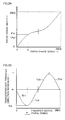
- the normal press operation control section 61 and 63 read the slide motion information (see FIG. 2A ) corresponding to each servo press 10 selected from the first information storage section 64A illustrated in FIG. 1 . load the slide motion information into the work area 62, and output the press operation control signal Scp (press instruction value) while causing the step phase ti based on the slide motion information to advance (ST30 to ST32 in FIG. 6 ).
- the normal press operation control section 61 and 63 then perform normal press operation control that adjusts the actual slide position ⁇ ai (Pai) of the servo press 10 to the target slide position ⁇ si corresponding to the current step phase (step phase ti) illustrated in FIG. 2A .
- the press controller 25 of the servo press 10 that has received the press operation control signal Scp (press instruction value) controls the rotation of the press motor 21 based on the press instruction value Scp (target value) and the signals Sp and Sv (feedback signals) from the encoder 22.
- the slide 12 is then moved upward and downward, and normal press operation control is performed (ST32).
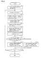
- the normal transfer operation control section 61 and 63 read the transfer motion information corresponding to the upstream-side servo transfer device 30U illustrated in FIG. 13 stored in the second information storage section 64B, load the transfer motion information into the work area 62, and output the transfer operation control signal Sctu (transfer instruction value) while causing the step phase ti based on the transfer motion information (the same as the step phase ti based on the slide motion information) to advance (ST10 to ST12 in FIG. 4 ). Specifically, the normal transfer operation control section 61 and 63 perform normal transfer operation control that adjusts the actual transfer position Xai to the target transfer position Xsi corresponding to the current step phase (step phase ti) illustrated in FIG 2B .
- the normal transfer operation control section 61 and 63 perform normal downstream-side transfer operation control on the downstream-side servo transfer device 30D (ST50 to ST52 in FIG. 8 ).
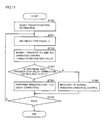
- the upstream-side transfer step delay determination section 61 and 63 read the step phase (e.g., ts4) at a time (e.g., t4) during normal transfer operation control (Tr3 and Tr4) referring to (B) in FIG. 5 , and store the step phase in the work area of the storage section 62 (ST13 in FIG. 4 ).
- the upstream-side transfer step delay determination section 61 and 63 cause the transfer position detection section 52, 61, and 63 to detect the actual transfer position Xa4 (ST14).
- the upstream-side transfer step delay determination section 61 and 63 then calculate the step phase ta4 (apparent step phase) of the upstream-side transfer step corresponding to the actual transfer position Xa4 by utilizing the transfer motion information (see dotted line of (B) in FIG. 5 ) (ST15).
- the upstream-side transfer step delay determination section 61 and 63 then determine whether or not the upstream-side transfer step Tr41 is delayed using the current step phase ts4 and the apparent step phase ta4.
- the upstream-side transfer step delay determination section 61 and 63 may determine that the upstream-side transfer step Tr41 is delayed when the step phase relationship is ta4 ⁇ ts4
- the allowable phase range ⁇ t4 is selected, set, and stored based on an allowable value during normal transfer operation, and is temporarily stored in the work memory in the step ST13.
- the target position ⁇ s4 is lower (e.g., closer to the bottom dead center) than the actual position ⁇ a4 corresponding to the apparent step phase ta4. Therefore, the slide 12 may enter (e.g., may be moved downward into) the downward movement interference area (i.e., interference may occur) in a period in which the rear end of the upstream-side servo transfer device 30U is positioned between the upper and lower dies 13 and 17 during the empty transfer step Tr4 or Tr41 (see FIG. 3B ).
- the slide downward movement step delay correction instruction section and the slide downward movement step delay correction control section are operated in order to prevent such a situation.
- the slide downward movement step delay correction instruction section 61 and 63 output a correction instruction that delays the slide downward movement step from the top dead center to the bottom dead center to the servo press 10 disposed on the downstream side of the upstream-side servo transfer device 30U in the direction X (ST18 in FIG. 4 ).
- the slide downward movement step delay correction instruction section 61 and 63 instruct the servo press 10 to increase the time required for the slide 12 to reach a position equal to or lower than the downward movement interference position illustrated in FIG. 3B .
- the slide downward movement step delay correction control section 61 and 63 have confirmed that the instruction has been received during the downward movement of the slide (NO in ST33 in FIG. 6 ) (YES in ST41), the servo press 10 causes the slide downward movement step delay correction control section 61 and 63 to perform a delay correction (ST42).
- the servo press 10 since the transfer step Tr41 is continuously performed even with a delay corresponding to the step phase ti, the servo press 10 is formed so that the operation speed can be temporarily reduced while controlling the operation corresponding to the step phase ti. Specifically, the servo press 10 waits for the transfer step Tr41 to catch up with the slide operation.
- the deceleration rate or the deceleration time can be set at a value proportional to the difference ⁇ tsa4.
- the slide downward movement step delay correction is not limited to the above-described deceleration method.
- the slide may be temporarily stopped once or several times.
- the invention effectively utilizes a phenomenon in which the slide position ⁇ i and the transfer position Xi return to the state ⁇ si and the state Xsi corresponding to the step phase tsi while the operation speed of the slide downward movement step of the servo press 10 is reduced by the slide downward movement step delay correction.
- the invention utilizes a phenomenon in which the delay is automatically canceled (NO in ST17 in FIG. 4 ).
- the press step delay determination section 61 and 63 then calculates the step phase ta1 (apparent step phase) corresponding to the detected actual slide position ⁇ a1 (ST36).
- the slide upward movement step delay determination section 61 and 63 then determine whether or not the slide upward movement step is delayed using the current step phase ts1 and the apparent step phase ta1 during the upward movement of the slide during press operation control.
- the apparent step phase ta1 is calculated referring to the slide motion information (see dotted line in (A) in FIG. 7 ).
- the slide upward movement step delay determination section 61 and 63 may determine that the slide upward movement step is delayed when the step phase relationship is ta1 ⁇ ts1.
- the allowable phase range ⁇ t2 is selected, set, and stored based on an allowable value during normal press operation, and is temporarily stored in the work memory in the step ST34.
- the downstream-side transfer step delay correction instruction section 61 and 63 output a correction instruction that causes the transfer step Tr11 of the servo transfer device 30D disposed on the downstream side of the servo press 10 to be delayed as compared with normal transfer operation control (ST39).
- the downstream-side transfer step delay correction instruction section 61 and 63 instruct an increase in the time required for the slide 13 illustrated in FIG. 3A to move upward to a sufficient height
- the downstream-side transfer step delay correction instruction section 61 and 63 instruct an increase in the time required for the servo transfer device to enter the space between the upper and lower dies illustrated in FIG.
- the slide position ⁇ i and the transfer position Xi return to the state ⁇ si and the state Xsi corresponding to the step phase tsi while the operation speed of the empty transfer step Tr11 is reduced by the downstream-side transfer step delay correction.
- the invention utilizes a phenomenon in which the delay in the slide upward movement step is automatically canceled.
- the downstream-side transfer step delay correction cancellation instruction section 61 and 63 have confirmed that the delay in the slide upward movement step has been canceled ( ⁇ tsa1 ⁇ t1) (NO in ST38 in FIG. 6 )
- the downstream-side transfer step delay correction cancellation instruction section 61 and 63 issue a cancellation instruction (ST40).
- recovery control section 61 and 63 of the servo transfer device 30D cancel the deceleration operation (ST55) to recover the normal transfer operation by the normal transfer operation control section 61 and 63 (ST52).
- the host controller 60 integrally controls each servo press 10 and each servo transfer device 30 from the viewpoint of improving the productivity of the entire servo press line Therefore, even if the slide upward movement step of the servo press 10 is delayed or the transfer step Tr41 of the servo transfer device 30U (upstream side) is delayed in the press cycle or the transfer cycle, integral control is not impaired due to such a change Therefore, operation control stability of the entire press line is achieved.
- the downstream-side transfer step Tr11 is delayed. Specifically, the transfer step is decelerated until the slide 12 is moved upward to a position equal to or higher than a given height, and the downstream-side transfer step Tr11 is then returned to the normal transfer step. Specifically, a speed mismatch is automatically corrected by an individual control method that locally monitors an arbitrary servo press 10 and the servo transfer device 30D disposed on the downstream side of the servo press 10. This reliably prevents interference. Since a delay in the slide upward movement step does not occur in each cycle, the productivity is affected to only a small extent.
- the relatively low-speed servo transfer device 30 can be subjected to a transfer operation in a top speed mode and the relatively high-speed servo press 10 can perform a press operation at a slide speed (cycle) corresponding to the transfer operation of the servo transfer device 30 in the top speed mode in order to maximize productivity, the transfer speed and the slide speed do not become higher than those of the normal operation. Specifically, since interference can be prevented by the individual control methods for the downstream-side transfer step and the slide downward movement step (i.e., delay correction), integral control is not affected to a large extent.
- the servo press line operation method according to the invention can be implemented reliably and smoothly, interference can be reliably prevented while maximizing press productivity.
- the normal press operation control section can perform normal press operation control so that the actual slide position ⁇ a is adjusted to the target slide position ⁇ s corresponding to the current step phase
- the normal transfer operation control section can perform normal transfer operation control so that the actual transfer position Xa is adjusted to the target transfer position Xs corresponding to the current step phase
- the downstream-side transfer step delay correction control section can delay the downstream-side transfer step when the upward movement step delay determination section has determined that the slide upward movement step is delayed
- the slide downward movement step delay correction control section can delay the slide downward movement step when the upstream-side transfer step delay determination section has determined that the upstream-side transfer step is delayed
- the servo press line operation control device can be easily implemented and allows simple handling
- the servo press line operation control device is formed so that the upward movement step can be determined to be delayed when the difference between the current step phase and the apparent step phase is larger than the first set phase range ⁇ t1 and the upstream-side transfer step can be determined to be delayed when the difference between the current step phase and the apparent step phase is larger than the second set phase range ⁇ t4, more stable slide upward/downward movement control and transfer control can be performed.
- the servo press line operation control device can be flexibly employed for an arbitrary servo press line irrespective of the types and the structures of the servo press 10 and the servo transfer device 30. Therefore, the servo press line operation control device has high industrial applicability.
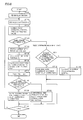
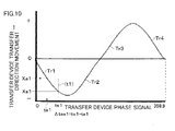
- the normal transfer operation control section 61 and 63 for the downstream-side servo transfer device 30D read transfer motion information illustrated in FIG. 10 , load the transfer motion information into the work area 62, and output the transfer operation control signal Sctd (transfer instruction value) while causing the step phase ti to advance (ST60 to ST62 in FIG. 9 ). Specifically, the normal transfer operation control section 61 and 63 perform normal transfer operation control that adjusts the actual transfer position Xa1 to the target transfer position Xsi corresponding to the current step phase (step phase t1) illustrated in FIG. 10 .
- the transfer controller 55 of the downstream-side servo transfer device 30D that has received the transfer operation control signal Sctd (transfer instruction value) controls the rotation of the transfer motor 51 based on the transfer instruction value Sctd (target value) and the signals Sp and Sv (feedback signals) from the encoder 52.
- the carrier 32 is then moved rightward and leftward, and normal downstream-side transfer operation control is performed (ST62).
- the normal transfer operation control section 61 and 63 for the upstream-side servo transfer device 30U perform normal upstream-side transfer operation control (ST80 to ST82 in FIG. 11 ).
- the downstream-side transfer step delay determination section 61 and 63 read the step phase ts1 at the time t1 during empty transfer operation control (Tr12 and/or Tr11) before the normal workpiece transfer step Tr2 (Tr21) referring to FIG. 10 , and store the step phase ts1 in the work area (storage section 62) (ST63 in FIG. 9 ).
- the downstream-side transfer step delay determination section 61 and 63 cause the transfer position detection section 52, 61, and 63 to detect the actual transfer position Xa1 (ST64).
- the downstream-side transfer step delay determination section 61 and 63 then calculate the apparent step phase ta1 of the downstream-side transfer step Tr1 corresponding to the actual transfer position Xa1 utilizing the transfer motion information (see dotted line in FIG. 10 ). The downstream-side transfer step delay determination section 61 and 63 then determine whether or not the downstream-side transfer step Tr12 is delayed using the step phase ts1 and the apparent step phase ta1 during control.
- the allowable phase range ⁇ t1 is selected, set, and stored based on an allowable value during normal transfer operation, and is temporarily stored in the work memory in the step ST63.
- the downstream-side transfer step delay determination section 61 and 63 may determine that the downstream-side transfer step Tr12 is delayed when the phase relationship is ta1 ⁇ ts1
- the current step phase of the downstream-side servo transfer device 30D should be the step phase ts1 illustrated in FIG. 10 , and the transfer position should be equal to the target position Xs1.
- the actual transfer position is the detected transfer position Xa1.
- the step phase corresponding to the actual transfer position Xa1 is the apparent step phase ta1.
- the apparent step phase ta1 is delayed with respect to the step phase ts1.
- the workpiece transfer step Tr3 (Tr32) of the upstream-side servo transfer device 30U may proceed before the rear end of the downstream-side servo transfer device 30D during the empty transfer step Tr1 (Tr11) (see FIG. 3A ) reaches the lower die 17 or the workpiece transfer step Tr2 (Tr21) starts so that the front end of the workpiece 35 may enter the space between the upper and lower dies In this case, the transfer devices or the workpieces collide (i.e., interference occurs).
- the upstream-side transfer step delay correction instruction section 61 and 63 output a correction instruction that delays the transfer step Tr3 (Tr31 and/or Tr32) of the upstream-side servo transfer device 30U (ST68). Specifically, the upstream-side transfer step delay correction instruction section 61 and 63 instruct an increase in the time required for the front end of the workpiece 35 to reach the lower die 17.
- the upstream-side transfer step delay correction control section 61 and 63 perform a delay correction (ST84).
- the upstream-side servo transfer device 30U is formed so that the operation speed of the upstream-side transfer step Tr3 (Tr31 and Tr32) can be temporarily reduced while controlling the operation corresponding to the step phase ti.
- the upstream-side servo transfer device 30U waits for the workpiece 35 to be removed from the lower die 17 due to the progress of the downstream-side transfer step Tr2 (Tr21).
- the upstream-side transfer step delay correction is not limited to the above-described deceleration method.
- the transfer device may be temporarily stopped once or several times.
- the invention effectively utilizes a phenomenon in which the downstream-side transfer position Xi returns to the state Xsi corresponding to the step phase tsi while the operation speed of the workpiece transfer step Tr3 is reduced by the upstream-side transfer step delay correction. Specifically, the delay in the downstream-side transfer step Tr2 (Tr21) is automatically canceled. Specifically, when the upstream-side transfer step delay correction cancellation instruction section 61 and 63 have confirmed that the delay in the workpiece transfer step Tr21 has been canceled ( ⁇ tsa1 ⁇ t1) (NO in ST67), the upstream-side transfer step delay correction cancellation instruction section 61 and 63 issue a cancellation instruction (ST69). Note that the upstream-side transfer step delay correction cancellation instruction section may be formed by interference area escape confirmation section 61 and 63 in the same manner as in the first embodiment.
- recovery control section 61 and 63 of the upstream-side servo transfer device 30U cancel the deceleration operation (ST85) to recover the normal transfer operation by the normal transfer operation control section 61 and 63 (ST82)
- the workpiece transfer step (Tr3) is decelerated until the workpiece transfer step Tr2 of the downstream-side servo transfer device 30D advances and the rear end of the downstream-side servo transfer device 30D is removed from the lower die 17 in the direction X, and the workpiece transfer step Tr3 is then returned to the normal downward movement step
- a speed mismatch between the upstream-side servo transfer device 30U and the downstream-side servo transfer device 30D is automatically corrected by an individual control method that locally monitors the upstream-side servo transfer device 30U and the downstream-side servo transfer device 30D disposed on either side of an arbitrary servo press 10 so that interference during the transfer step can be reliably prevented.
- the same effects as those of the first embodiment can be achieved while further reliably preventing interference between the servo transfer devices 30U and 30D.
- the servo press line can be operated utilizing a correction between the upstream-side and the downstream-side servo transfer devices 30U and 30D without performing a correction for the servo press 10 under conditions where a delay in the slide upward movement step and the slide downward movement step of the servo press 10 rarely occurs (e.g., when the load is very small with respect to the capacity of the servo press 10). Therefore, the application range can be further increased.
- the invention can contribute to providing a servo press line that can perform a press operation while reliably preventing interference between the servo press and the servo transfer device or the workpiece and maximizing productivity.
Landscapes
- Engineering & Computer Science (AREA)
- Mechanical Engineering (AREA)
- General Engineering & Computer Science (AREA)
- Manufacturing & Machinery (AREA)
- Quality & Reliability (AREA)
- Physics & Mathematics (AREA)
- General Physics & Mathematics (AREA)
- Automation & Control Theory (AREA)
- Control Of Presses (AREA)
- Presses And Accessory Devices Thereof (AREA)
- Press Drives And Press Lines (AREA)
Applications Claiming Priority (1)
| Application Number | Priority Date | Filing Date | Title |
|---|---|---|---|
| JP2008176972A JP4702901B2 (ja) | 2008-07-07 | 2008-07-07 | サーボプレスラインの運転方法および運転制御装置 |
Publications (3)
| Publication Number | Publication Date |
|---|---|
| EP2144128A2 true EP2144128A2 (de) | 2010-01-13 |
| EP2144128A3 EP2144128A3 (de) | 2011-04-06 |
| EP2144128B1 EP2144128B1 (de) | 2013-09-25 |
Family
ID=41202623
Family Applications (1)
| Application Number | Title | Priority Date | Filing Date |
|---|---|---|---|
| EP09008779.2A Active EP2144128B1 (de) | 2008-07-07 | 2009-07-03 | Verfahren zum Betrieb einer Servopressenlinie und Vorrichtung zur Steuerung des Betriebs einer Servopresse |
Country Status (3)
| Country | Link |
|---|---|
| US (1) | US8096233B2 (de) |
| EP (1) | EP2144128B1 (de) |
| JP (1) | JP4702901B2 (de) |
Cited By (3)
| Publication number | Priority date | Publication date | Assignee | Title |
|---|---|---|---|---|
| WO2012055916A1 (de) * | 2010-10-26 | 2012-05-03 | Schuler Pressen Gmbh | Steuereinrichtung und verfahren zur steuerung der stationen einer fertigungsstrasse |
| EP2811355A1 (de) * | 2013-06-06 | 2014-12-10 | Aida Engineering, Ltd. | Servotransferzufuhreinrichtung und Verfahren zur Steuerung einer Servotransferzufuhreinrichtung |
| DE102012020797B4 (de) * | 2011-10-26 | 2015-09-24 | Aida Engineering, Ltd. | Servotransferpressensystem |
Families Citing this family (8)
| Publication number | Priority date | Publication date | Assignee | Title |
|---|---|---|---|---|
| JP5138399B2 (ja) * | 2008-01-25 | 2013-02-06 | アイダエンジニアリング株式会社 | サーボプレス機械 |
| JP5688983B2 (ja) | 2011-01-28 | 2015-03-25 | アイダエンジニアリング株式会社 | サーボプレスシステム |
| JP5647059B2 (ja) * | 2011-04-27 | 2014-12-24 | アイダエンジニアリング株式会社 | タンデムプレスライン |
| JP5902500B2 (ja) * | 2012-02-10 | 2016-04-13 | 本田技研工業株式会社 | 搬送モーションの変更方法 |
| JP5844838B2 (ja) | 2013-05-30 | 2016-01-20 | アイダエンジニアリング株式会社 | サーボプレスラインの運転方法および運転制御装置 |
| US20180290198A1 (en) * | 2015-09-28 | 2018-10-11 | Aida Engineering, Ltd. | Operation control device and operation control method for press line |
| ES2697058B2 (es) * | 2017-07-19 | 2019-07-08 | Fagor Arrasate S Coop | Método de control para una instalación de prensas, e instalación asociada |
| EP3627258B1 (de) * | 2018-09-20 | 2024-07-31 | Siemens Aktiengesellschaft | Bewegungsplanung für eine servopresse |
Citations (4)
| Publication number | Priority date | Publication date | Assignee | Title |
|---|---|---|---|---|
| EP0837379A1 (de) | 1996-10-17 | 1998-04-22 | Müller-Weingarten AG | Hydraulische Transferpresse |
| JP2005297010A (ja) | 2004-04-13 | 2005-10-27 | Aida Eng Ltd | トランスファプレス運転方法およびトランスファプレス機械 |
| EP1615090A1 (de) | 2004-07-10 | 2006-01-11 | FAGOR, S.Coop | Vorrichtung zur synchronisierten Steuerung einer Reihe von Maschinen, insbesondere von Pressen |
| WO2007091964A2 (en) | 2006-02-06 | 2007-08-16 | Abb Research Ltd. | Press line system and method |
Family Cites Families (11)
| Publication number | Priority date | Publication date | Assignee | Title |
|---|---|---|---|---|
| JPS62179829A (ja) * | 1986-02-04 | 1987-08-07 | Aida Eng Ltd | フイ−ダ単独駆動トランスフアプレス |
| JP3528196B2 (ja) * | 1993-01-16 | 2004-05-17 | 株式会社安川電機 | プレス機に同期するロボットシステム |
| JPH08241126A (ja) * | 1995-03-02 | 1996-09-17 | Canon Inc | 同期位置制御方法および装置 |
| JP3773576B2 (ja) * | 1996-02-08 | 2006-05-10 | 株式会社小松製作所 | トランスファプレス |
| JP3818748B2 (ja) * | 1997-08-19 | 2006-09-06 | 株式会社小松製作所 | サーボプレスの起動位置設定装置及びその方法 |
| JP2000343294A (ja) | 1999-06-02 | 2000-12-12 | Yamada Dobby Co Ltd | トランスファプレスライン |
| JP2002316298A (ja) * | 2001-04-18 | 2002-10-29 | Komatsu Ltd | トランスファプレスおよびそのスライド駆動方法 |
| JP2003191096A (ja) | 2001-12-26 | 2003-07-08 | Aida Eng Ltd | プレス機械システム |
| JP4783106B2 (ja) * | 2004-10-04 | 2011-09-28 | 株式会社小松製作所 | プレス間同期制御装置 |
| JP4507250B2 (ja) * | 2004-10-29 | 2010-07-21 | アイダエンジニアリング株式会社 | トランスファプレス機械 |
| JP5019250B2 (ja) * | 2006-11-30 | 2012-09-05 | 株式会社Ihi | サーボプレス設備とその制御方法 |
-
2008
- 2008-07-07 JP JP2008176972A patent/JP4702901B2/ja active Active
-
2009
- 2009-07-03 EP EP09008779.2A patent/EP2144128B1/de active Active
- 2009-07-06 US US12/497,773 patent/US8096233B2/en not_active Expired - Fee Related
Patent Citations (4)
| Publication number | Priority date | Publication date | Assignee | Title |
|---|---|---|---|---|
| EP0837379A1 (de) | 1996-10-17 | 1998-04-22 | Müller-Weingarten AG | Hydraulische Transferpresse |
| JP2005297010A (ja) | 2004-04-13 | 2005-10-27 | Aida Eng Ltd | トランスファプレス運転方法およびトランスファプレス機械 |
| EP1615090A1 (de) | 2004-07-10 | 2006-01-11 | FAGOR, S.Coop | Vorrichtung zur synchronisierten Steuerung einer Reihe von Maschinen, insbesondere von Pressen |
| WO2007091964A2 (en) | 2006-02-06 | 2007-08-16 | Abb Research Ltd. | Press line system and method |
Cited By (6)
| Publication number | Priority date | Publication date | Assignee | Title |
|---|---|---|---|---|
| WO2012055916A1 (de) * | 2010-10-26 | 2012-05-03 | Schuler Pressen Gmbh | Steuereinrichtung und verfahren zur steuerung der stationen einer fertigungsstrasse |
| DE102012020797B4 (de) * | 2011-10-26 | 2015-09-24 | Aida Engineering, Ltd. | Servotransferpressensystem |
| EP2811355A1 (de) * | 2013-06-06 | 2014-12-10 | Aida Engineering, Ltd. | Servotransferzufuhreinrichtung und Verfahren zur Steuerung einer Servotransferzufuhreinrichtung |
| CN104226836A (zh) * | 2013-06-06 | 2014-12-24 | 会田工程技术有限公司 | 伺服多工位送料装置及伺服多工位送料装置的控制方法 |
| US9144903B2 (en) | 2013-06-06 | 2015-09-29 | Aida Engineering, Ltd. | Servo transfer feeder and method for controlling servo transfer feeder |
| CN104226836B (zh) * | 2013-06-06 | 2017-06-13 | 会田工程技术有限公司 | 伺服多工位送料装置及伺服多工位送料装置的控制方法 |
Also Published As
| Publication number | Publication date |
|---|---|
| JP4702901B2 (ja) | 2011-06-15 |
| EP2144128A3 (de) | 2011-04-06 |
| US20100000424A1 (en) | 2010-01-07 |
| EP2144128B1 (de) | 2013-09-25 |
| JP2010012511A (ja) | 2010-01-21 |
| US8096233B2 (en) | 2012-01-17 |
Similar Documents
| Publication | Publication Date | Title |
|---|---|---|
| EP2144128B1 (de) | Verfahren zum Betrieb einer Servopressenlinie und Vorrichtung zur Steuerung des Betriebs einer Servopresse | |
| US7049775B2 (en) | Servo motor control unit for press-forming machine | |
| EP2119557B1 (de) | Presse mit Steuerungsteil zum Einstellen der Lage des untersten Totpunktes | |
| US20100192788A1 (en) | Motor drive control device | |
| JP5647059B2 (ja) | タンデムプレスライン | |
| CN101024309B (zh) | 压力机线系统和方法 | |
| JP5665233B2 (ja) | サーボトランスファプレスシステム | |
| EP1798615A2 (de) | Festpositions-Anhaltesteuervorrichtung für eine Drehwelle | |
| US20140084838A1 (en) | Numerical controller having function for switching between pressure control and position control | |
| US9643232B2 (en) | Servo press line operation method and servo press line operation control device | |
| CN101122789A (zh) | 数值控制装置 | |
| JP5265533B2 (ja) | サイクリックな製造マシンをローダーまたはアンローダー・マシンと調整して運転するための改善された方法及びシステム | |
| JP5688983B2 (ja) | サーボプレスシステム | |
| US6474227B2 (en) | Method of controlling synchronous drive of pressing machine and pressing machine usable in the method | |
| JPH1158094A (ja) | サーボプレスの起動位置設定装置及びその方法 | |
| TWI486231B (zh) | 扭矩控制裝置 | |
| JP4783106B2 (ja) | プレス間同期制御装置 | |
| JP2001300793A (ja) | プレス機の同期駆動制御方法及びそれに用いるプレス機 | |
| JP2001134321A (ja) | 数値制御装置 | |
| TW202535573A (zh) | 折彎系統及折彎方法 | |
| JP2005262285A (ja) | トランスファプレス機械 | |
| US20230152782A1 (en) | Controller | |
| TW201000305A (en) | Method for synchronously controlling dual machines, control device and dual machine synchronous punching system | |
| JPS62133022A (ja) | 揺動式粗割機の自動運転制御方法 |
Legal Events
| Date | Code | Title | Description |
|---|---|---|---|
| PUAI | Public reference made under article 153(3) epc to a published international application that has entered the european phase |
Free format text: ORIGINAL CODE: 0009012 |
|
| AK | Designated contracting states |
Kind code of ref document: A2 Designated state(s): AT BE BG CH CY CZ DE DK EE ES FI FR GB GR HR HU IE IS IT LI LT LU LV MC MK MT NL NO PL PT RO SE SI SK SM TR |
|
| PUAL | Search report despatched |
Free format text: ORIGINAL CODE: 0009013 |
|
| AK | Designated contracting states |
Kind code of ref document: A3 Designated state(s): AT BE BG CH CY CZ DE DK EE ES FI FR GB GR HR HU IE IS IT LI LT LU LV MC MK MT NL NO PL PT RO SE SI SK SM TR |
|
| AX | Request for extension of the european patent |
Extension state: AL BA RS |
|
| RIC1 | Information provided on ipc code assigned before grant |
Ipc: G05B 19/418 20060101AFI20091027BHEP Ipc: B30B 15/28 20060101ALI20110225BHEP |
|
| 17P | Request for examination filed |
Effective date: 20111005 |
|
| RIC1 | Information provided on ipc code assigned before grant |
Ipc: B30B 15/28 20060101ALI20130311BHEP Ipc: G05B 19/418 20060101AFI20130311BHEP |
|
| GRAP | Despatch of communication of intention to grant a patent |
Free format text: ORIGINAL CODE: EPIDOSNIGR1 |
|
| INTG | Intention to grant announced |
Effective date: 20130419 |
|
| GRAS | Grant fee paid |
Free format text: ORIGINAL CODE: EPIDOSNIGR3 |
|
| GRAA | (expected) grant |
Free format text: ORIGINAL CODE: 0009210 |
|
| AK | Designated contracting states |
Kind code of ref document: B1 Designated state(s): AT BE BG CH CY CZ DE DK EE ES FI FR GB GR HR HU IE IS IT LI LT LU LV MC MK MT NL NO PL PT RO SE SI SK SM TR |
|
| REG | Reference to a national code |
Ref country code: GB Ref legal event code: FG4D |
|
| REG | Reference to a national code |
Ref country code: CH Ref legal event code: EP |
|
| REG | Reference to a national code |
Ref country code: AT Ref legal event code: REF Ref document number: 633946 Country of ref document: AT Kind code of ref document: T Effective date: 20131015 |
|
| REG | Reference to a national code |
Ref country code: IE Ref legal event code: FG4D |
|
| REG | Reference to a national code |
Ref country code: DE Ref legal event code: R096 Ref document number: 602009019003 Country of ref document: DE Effective date: 20131121 |
|
| PG25 | Lapsed in a contracting state [announced via postgrant information from national office to epo] |
Ref country code: LT Free format text: LAPSE BECAUSE OF FAILURE TO SUBMIT A TRANSLATION OF THE DESCRIPTION OR TO PAY THE FEE WITHIN THE PRESCRIBED TIME-LIMIT Effective date: 20130925 Ref country code: NO Free format text: LAPSE BECAUSE OF FAILURE TO SUBMIT A TRANSLATION OF THE DESCRIPTION OR TO PAY THE FEE WITHIN THE PRESCRIBED TIME-LIMIT Effective date: 20131225 Ref country code: HR Free format text: LAPSE BECAUSE OF FAILURE TO SUBMIT A TRANSLATION OF THE DESCRIPTION OR TO PAY THE FEE WITHIN THE PRESCRIBED TIME-LIMIT Effective date: 20130925 Ref country code: SE Free format text: LAPSE BECAUSE OF FAILURE TO SUBMIT A TRANSLATION OF THE DESCRIPTION OR TO PAY THE FEE WITHIN THE PRESCRIBED TIME-LIMIT Effective date: 20130925 |
|
| REG | Reference to a national code |
Ref country code: AT Ref legal event code: MK05 Ref document number: 633946 Country of ref document: AT Kind code of ref document: T Effective date: 20130925 |
|
| REG | Reference to a national code |
Ref country code: NL Ref legal event code: VDEP Effective date: 20130925 |
|
| REG | Reference to a national code |
Ref country code: LT Ref legal event code: MG4D |
|
| PG25 | Lapsed in a contracting state [announced via postgrant information from national office to epo] |
Ref country code: SI Free format text: LAPSE BECAUSE OF FAILURE TO SUBMIT A TRANSLATION OF THE DESCRIPTION OR TO PAY THE FEE WITHIN THE PRESCRIBED TIME-LIMIT Effective date: 20130925 Ref country code: GR Free format text: LAPSE BECAUSE OF FAILURE TO SUBMIT A TRANSLATION OF THE DESCRIPTION OR TO PAY THE FEE WITHIN THE PRESCRIBED TIME-LIMIT Effective date: 20131226 Ref country code: LV Free format text: LAPSE BECAUSE OF FAILURE TO SUBMIT A TRANSLATION OF THE DESCRIPTION OR TO PAY THE FEE WITHIN THE PRESCRIBED TIME-LIMIT Effective date: 20130925 Ref country code: FI Free format text: LAPSE BECAUSE OF FAILURE TO SUBMIT A TRANSLATION OF THE DESCRIPTION OR TO PAY THE FEE WITHIN THE PRESCRIBED TIME-LIMIT Effective date: 20130925 |
|
| PG25 | Lapsed in a contracting state [announced via postgrant information from national office to epo] |
Ref country code: BE Free format text: LAPSE BECAUSE OF FAILURE TO SUBMIT A TRANSLATION OF THE DESCRIPTION OR TO PAY THE FEE WITHIN THE PRESCRIBED TIME-LIMIT Effective date: 20130925 |
|
| PG25 | Lapsed in a contracting state [announced via postgrant information from national office to epo] |
Ref country code: NL Free format text: LAPSE BECAUSE OF FAILURE TO SUBMIT A TRANSLATION OF THE DESCRIPTION OR TO PAY THE FEE WITHIN THE PRESCRIBED TIME-LIMIT Effective date: 20130925 Ref country code: RO Free format text: LAPSE BECAUSE OF FAILURE TO SUBMIT A TRANSLATION OF THE DESCRIPTION OR TO PAY THE FEE WITHIN THE PRESCRIBED TIME-LIMIT Effective date: 20130925 Ref country code: SK Free format text: LAPSE BECAUSE OF FAILURE TO SUBMIT A TRANSLATION OF THE DESCRIPTION OR TO PAY THE FEE WITHIN THE PRESCRIBED TIME-LIMIT Effective date: 20130925 Ref country code: EE Free format text: LAPSE BECAUSE OF FAILURE TO SUBMIT A TRANSLATION OF THE DESCRIPTION OR TO PAY THE FEE WITHIN THE PRESCRIBED TIME-LIMIT Effective date: 20130925 Ref country code: CZ Free format text: LAPSE BECAUSE OF FAILURE TO SUBMIT A TRANSLATION OF THE DESCRIPTION OR TO PAY THE FEE WITHIN THE PRESCRIBED TIME-LIMIT Effective date: 20130925 Ref country code: IS Free format text: LAPSE BECAUSE OF FAILURE TO SUBMIT A TRANSLATION OF THE DESCRIPTION OR TO PAY THE FEE WITHIN THE PRESCRIBED TIME-LIMIT Effective date: 20140125 |
|
| PG25 | Lapsed in a contracting state [announced via postgrant information from national office to epo] |
Ref country code: AT Free format text: LAPSE BECAUSE OF FAILURE TO SUBMIT A TRANSLATION OF THE DESCRIPTION OR TO PAY THE FEE WITHIN THE PRESCRIBED TIME-LIMIT Effective date: 20130925 Ref country code: ES Free format text: LAPSE BECAUSE OF FAILURE TO SUBMIT A TRANSLATION OF THE DESCRIPTION OR TO PAY THE FEE WITHIN THE PRESCRIBED TIME-LIMIT Effective date: 20130925 Ref country code: PL Free format text: LAPSE BECAUSE OF FAILURE TO SUBMIT A TRANSLATION OF THE DESCRIPTION OR TO PAY THE FEE WITHIN THE PRESCRIBED TIME-LIMIT Effective date: 20130925 Ref country code: CY Free format text: LAPSE BECAUSE OF FAILURE TO SUBMIT A TRANSLATION OF THE DESCRIPTION OR TO PAY THE FEE WITHIN THE PRESCRIBED TIME-LIMIT Effective date: 20130925 |
|
| REG | Reference to a national code |
Ref country code: DE Ref legal event code: R097 Ref document number: 602009019003 Country of ref document: DE |
|
| PG25 | Lapsed in a contracting state [announced via postgrant information from national office to epo] |
Ref country code: PT Free format text: LAPSE BECAUSE OF FAILURE TO SUBMIT A TRANSLATION OF THE DESCRIPTION OR TO PAY THE FEE WITHIN THE PRESCRIBED TIME-LIMIT Effective date: 20140127 |
|
| PLBE | No opposition filed within time limit |
Free format text: ORIGINAL CODE: 0009261 |
|
| STAA | Information on the status of an ep patent application or granted ep patent |
Free format text: STATUS: NO OPPOSITION FILED WITHIN TIME LIMIT |
|
| 26N | No opposition filed |
Effective date: 20140626 |
|
| PG25 | Lapsed in a contracting state [announced via postgrant information from national office to epo] |
Ref country code: DK Free format text: LAPSE BECAUSE OF FAILURE TO SUBMIT A TRANSLATION OF THE DESCRIPTION OR TO PAY THE FEE WITHIN THE PRESCRIBED TIME-LIMIT Effective date: 20130925 |
|
| REG | Reference to a national code |
Ref country code: DE Ref legal event code: R097 Ref document number: 602009019003 Country of ref document: DE Effective date: 20140626 |
|
| PG25 | Lapsed in a contracting state [announced via postgrant information from national office to epo] |
Ref country code: LU Free format text: LAPSE BECAUSE OF FAILURE TO SUBMIT A TRANSLATION OF THE DESCRIPTION OR TO PAY THE FEE WITHIN THE PRESCRIBED TIME-LIMIT Effective date: 20140703 |
|
| REG | Reference to a national code |
Ref country code: CH Ref legal event code: PL |
|
| GBPC | Gb: european patent ceased through non-payment of renewal fee |
Effective date: 20140703 |
|
| REG | Reference to a national code |
Ref country code: IE Ref legal event code: MM4A |
|
| REG | Reference to a national code |
Ref country code: FR Ref legal event code: ST Effective date: 20150331 |
|
| PG25 | Lapsed in a contracting state [announced via postgrant information from national office to epo] |
Ref country code: LI Free format text: LAPSE BECAUSE OF NON-PAYMENT OF DUE FEES Effective date: 20140731 Ref country code: CH Free format text: LAPSE BECAUSE OF NON-PAYMENT OF DUE FEES Effective date: 20140731 |
|
| PG25 | Lapsed in a contracting state [announced via postgrant information from national office to epo] |
Ref country code: FR Free format text: LAPSE BECAUSE OF NON-PAYMENT OF DUE FEES Effective date: 20140731 Ref country code: GB Free format text: LAPSE BECAUSE OF NON-PAYMENT OF DUE FEES Effective date: 20140703 |
|
| PG25 | Lapsed in a contracting state [announced via postgrant information from national office to epo] |
Ref country code: IE Free format text: LAPSE BECAUSE OF NON-PAYMENT OF DUE FEES Effective date: 20140703 |
|
| PG25 | Lapsed in a contracting state [announced via postgrant information from national office to epo] |
Ref country code: SM Free format text: LAPSE BECAUSE OF FAILURE TO SUBMIT A TRANSLATION OF THE DESCRIPTION OR TO PAY THE FEE WITHIN THE PRESCRIBED TIME-LIMIT Effective date: 20130925 Ref country code: MC Free format text: LAPSE BECAUSE OF FAILURE TO SUBMIT A TRANSLATION OF THE DESCRIPTION OR TO PAY THE FEE WITHIN THE PRESCRIBED TIME-LIMIT Effective date: 20130925 |
|
| PG25 | Lapsed in a contracting state [announced via postgrant information from national office to epo] |
Ref country code: BG Free format text: LAPSE BECAUSE OF FAILURE TO SUBMIT A TRANSLATION OF THE DESCRIPTION OR TO PAY THE FEE WITHIN THE PRESCRIBED TIME-LIMIT Effective date: 20130925 Ref country code: MT Free format text: LAPSE BECAUSE OF FAILURE TO SUBMIT A TRANSLATION OF THE DESCRIPTION OR TO PAY THE FEE WITHIN THE PRESCRIBED TIME-LIMIT Effective date: 20130925 |
|
| PG25 | Lapsed in a contracting state [announced via postgrant information from national office to epo] |
Ref country code: HU Free format text: LAPSE BECAUSE OF FAILURE TO SUBMIT A TRANSLATION OF THE DESCRIPTION OR TO PAY THE FEE WITHIN THE PRESCRIBED TIME-LIMIT; INVALID AB INITIO Effective date: 20090703 Ref country code: TR Free format text: LAPSE BECAUSE OF FAILURE TO SUBMIT A TRANSLATION OF THE DESCRIPTION OR TO PAY THE FEE WITHIN THE PRESCRIBED TIME-LIMIT Effective date: 20130925 |
|
| PG25 | Lapsed in a contracting state [announced via postgrant information from national office to epo] |
Ref country code: MK Free format text: LAPSE BECAUSE OF FAILURE TO SUBMIT A TRANSLATION OF THE DESCRIPTION OR TO PAY THE FEE WITHIN THE PRESCRIBED TIME-LIMIT Effective date: 20130925 |
|
| PGFP | Annual fee paid to national office [announced via postgrant information from national office to epo] |
Ref country code: IT Payment date: 20180720 Year of fee payment: 10 |
|
| PG25 | Lapsed in a contracting state [announced via postgrant information from national office to epo] |
Ref country code: IT Free format text: LAPSE BECAUSE OF NON-PAYMENT OF DUE FEES Effective date: 20190703 |
|
| PGFP | Annual fee paid to national office [announced via postgrant information from national office to epo] |
Ref country code: DE Payment date: 20250528 Year of fee payment: 17 |