EP1615090A1 - Vorrichtung zur synchronisierten Steuerung einer Reihe von Maschinen, insbesondere von Pressen - Google Patents
Vorrichtung zur synchronisierten Steuerung einer Reihe von Maschinen, insbesondere von Pressen Download PDFInfo
- Publication number
- EP1615090A1 EP1615090A1 EP04380144A EP04380144A EP1615090A1 EP 1615090 A1 EP1615090 A1 EP 1615090A1 EP 04380144 A EP04380144 A EP 04380144A EP 04380144 A EP04380144 A EP 04380144A EP 1615090 A1 EP1615090 A1 EP 1615090A1
- Authority
- EP
- European Patent Office
- Prior art keywords
- path
- transfer device
- press
- piece transfer
- slide
- Prior art date
- Legal status (The legal status is an assumption and is not a legal conclusion. Google has not performed a legal analysis and makes no representation as to the accuracy of the status listed.)
- Granted
Links
Images


Classifications
-
- G—PHYSICS
- G05—CONTROLLING; REGULATING
- G05B—CONTROL OR REGULATING SYSTEMS IN GENERAL; FUNCTIONAL ELEMENTS OF SUCH SYSTEMS; MONITORING OR TESTING ARRANGEMENTS FOR SUCH SYSTEMS OR ELEMENTS
- G05B19/00—Programme-control systems
- G05B19/02—Programme-control systems electric
- G05B19/418—Total factory control, i.e. centrally controlling a plurality of machines, e.g. direct or distributed numerical control [DNC], flexible manufacturing systems [FMS], integrated manufacturing systems [IMS], computer integrated manufacturing [CIM]
- G05B19/41815—Total factory control, i.e. centrally controlling a plurality of machines, e.g. direct or distributed numerical control [DNC], flexible manufacturing systems [FMS], integrated manufacturing systems [IMS], computer integrated manufacturing [CIM] characterised by the cooperation between machine tools, manipulators and conveyor or other workpiece supply system, workcell
-
- G—PHYSICS
- G05—CONTROLLING; REGULATING
- G05B—CONTROL OR REGULATING SYSTEMS IN GENERAL; FUNCTIONAL ELEMENTS OF SUCH SYSTEMS; MONITORING OR TESTING ARRANGEMENTS FOR SUCH SYSTEMS OR ELEMENTS
- G05B2219/00—Program-control systems
- G05B2219/30—Nc systems
- G05B2219/39—Robotics, robotics to robotics hand
- G05B2219/39105—Manipulator cooperates with moving machine, like press brake
-
- G—PHYSICS
- G05—CONTROLLING; REGULATING
- G05B—CONTROL OR REGULATING SYSTEMS IN GENERAL; FUNCTIONAL ELEMENTS OF SUCH SYSTEMS; MONITORING OR TESTING ARRANGEMENTS FOR SUCH SYSTEMS OR ELEMENTS
- G05B2219/00—Program-control systems
- G05B2219/30—Nc systems
- G05B2219/45—Nc applications
- G05B2219/45142—Press-line
-
- Y—GENERAL TAGGING OF NEW TECHNOLOGICAL DEVELOPMENTS; GENERAL TAGGING OF CROSS-SECTIONAL TECHNOLOGIES SPANNING OVER SEVERAL SECTIONS OF THE IPC; TECHNICAL SUBJECTS COVERED BY FORMER USPC CROSS-REFERENCE ART COLLECTIONS [XRACs] AND DIGESTS
- Y02—TECHNOLOGIES OR APPLICATIONS FOR MITIGATION OR ADAPTATION AGAINST CLIMATE CHANGE
- Y02P—CLIMATE CHANGE MITIGATION TECHNOLOGIES IN THE PRODUCTION OR PROCESSING OF GOODS
- Y02P90/00—Enabling technologies with a potential contribution to greenhouse gas [GHG] emissions mitigation
- Y02P90/02—Total factory control, e.g. smart factories, flexible manufacturing systems [FMS] or integrated manufacturing systems [IMS]
Definitions
- the present invention relates to control systems of lines of machines and more specifically to control systems of lines of presses.
- Lines of presses and analogous machines used to carry out a process to form pieces, mainly metal plates, are already known.
- a specific forming operation is conducted on the pieces, which are then transferred successively between lines of presses by piece transfer devices such as crossbars or various types of piece handling robots.
- Said piece transfer devices are positioned between the presses in the line and link the press immediately upstream and the press immediately downstream so that the pieces can be transferred between said presses.
- Each press comprises a slide which performs a cyclical movement between an inoperative and an operative position so that the corresponding forming operation can be performed.
- the cyclical movement of the slide can be represented by a cyclogram in which an angle of 0° usually corresponds to the top dead centre of said slide.
- One complete stroke of the slide equates to one complete rotation of the cyclogram and each angle on the cyclogram corresponds to a specific position of the slide with bottom dead centre, for example, corresponding to an angle of 180°.
- EP 0434632 A2 describes a machine and a method for controlling the operation of a line of machines, particularly presses.
- this machine the operating cycles of the presses and the piece transfer devices of the line are synchronised.
- the operating cycle of the first press of the line is taken as the reference with the cycles of the other presses and the piece transfer devices being obtained in a cascade process.
- each piece transfer device starts running when the slide of the press immediately upstream reaches a certain point.
- the slide of each machine downstream from the first machine starts to move cyclically when the piece transfer device immediately downstream reaches a certain point.
- the first press in the line of presses described above operates continuously, i.e. the slide does not stop at top dead centre.
- the slide in the other presses performs the cyclical movement and does stop at top dead centre until it receives the signal telling it that the piece transfer device immediately upstream has deposited the piece and has withdrawn to a certain point.
- the main object of the invention is to provide a synchronised control system of a line of presses or analogous machines that allows the presses and the piece transfer devices used to transfer the pieces between the presses to operate continuously, i.e. without stops and starts occuring during synchronised operation.
- an optimal piece collection path in relation to the cyclogram of the slide of the press immediately upstream is set for each piece transfer device, in addition to an optimal piece positioning path in relation to the cyclogram of the slide of the press immediately downstream. This ensures that the synchronisation of the presses and the piece transfer devices is achieved by adjusting the path of each piece transfer device to the aforementioned optimal collection path and to the aforementioned optimal positioning path.
- phase lags i.e. if a piece transfer device moves too quickly or slowly in relation to the press immediately upstream or the press immediately downstream, said phase lags are not compensated for by stopping the piece transfer device repeatedly but by adapting the path of the piece transfer device to the corresponding optimal path with the speed of the piece transfer device in question thus being changed as a result.
- the synchronised control system allows both the piece transfer devices and the presses to operate continuously. As the piece transfer devices and the presses do not need to be stopped and started again and again the amount of energy consumed by the line of presses is reduced. In addition, the fact that the presses operate continuously reduces wear on the components in said presses, i.e. clutches, brakes, gears, etc. The useful life of the presses is thus extended.
- the synchronised control system of the invention is applied to lines of presses and to analogous lines of forming machines.
- the lines of presses comprise a plurality of presses (P1, P2,..., Pn) with each of the presses (P1, P2,..., Pn) comprising a slide (M1, M2,..., Mn) which performs a cyclical movement between an inoperative and an operative position.
- Figure 2 shows a press (Pi) with said characteristics.
- the cyclical movement of each slide (Mi) is represented by a cyclogram in which an angle of 0° usually corresponds to the top dead centre (S) of the slide (Mi).
- the lines of presses also comprise a plurality of piece transfer devices (C1, C2,..., Cn-1) positioned between the presses (P1, P2,..., Pn) in order to transfer pieces between said presses (P1, P2,..., Pn) with each piece transfer device (Ci) performing a path (ri) between the press (Pi) immediately upstream and the press (Pi+1) immediately downstream to transfer the pieces, as shown in figure 4.
- C1, C2,..., Cn-1 positioned between the presses (P1, P2,..., Pn) in order to transfer pieces between said presses (P1, P2,..., Pn) with each piece transfer device (Ci) performing a path (ri) between the press (Pi) immediately upstream and the press (Pi+1) immediately downstream to transfer the pieces, as shown in figure 4.
- This path (ri) passes through a first region of interference (trli) in which said piece transfer device (Ci) may interfere with the slide (Mi) of the press (Pi) immediately upstream, and then through a second region of interference (tr2i) in which said piece transfer device (Ci) may interfere with the slide (Mi+1) of the press (Pi+1) immediately downstream.
- the control system of the invention establishes an optimal piece collection path (rori) in relation to the cyclogram of the slide (Mi) of the press (Pi) immediately upstream, and an optimal piece positioning path (roci) in relation to the cyclogram of the slide (Mi+1) of the press (Pi+1) immediately downstream.
- This ensures that the synchronisation of the presses (P1, P2,..., Pn) and the piece transfer devices (C1, C2,..., Cn-1) is achieved by adjusting the path (ri) of each piece transfer device (Ci) to the aforementioned optimal collection path (rori) and to the aforementioned optimal positioning path (roci).
- Said path (ri) corresponds with the optimal collection path (rori) in the first region of interference (trli) and corresponds with the optimal positioning path (roci) in the second region of interference (tr2i).
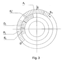
- Figure 3 shows, by way of example, the cyclogram of the slide (Mi) of the press (Pi) with the optimal collection path of the piece transfer device (Ci).
- the points at which the piece transfer device (Ci) has to advance, withdraw, lift up and descend are set in this cyclogram. More specifically, a withdrawal region (Ri) extending from point D up to the point at which the piece is collected is set along with an advance region (Ai), extending from this point up to a point (S1) along its path, a first elevation region (Ei), a descent region (Di) to access the piece and a second elevation region (Ei') to lift the piece up.
- a withdrawal region (Ri) extending from point D up to the point at which the piece is collected is set along with an advance region (Ai), extending from this point up to a point (S1) along its path, a first elevation region (Ei), a descent region (Di) to access the piece and a second elevation region (Ei') to lift the piece
- an optimal collection path (rori) is set for each piece transfer device (Ci) in accordance with the cyclogram of the slide (Mi) of the press (Pi) (see figure 5A) and an optimal positioning path (roci) in accordance with the cyclogram of the slide (Mi+1) of the press (Pi+1) (see figure 5B).
- the corresponding advance (Ai and Ai+1), withdrawal (Ri and Ri+1), descent (Di, Di+1 and Di+1') and elevation (Ei, Ei' and Ei+1) regions are set in each cyclogram.
- the path (ri) of the piece transfer device is adjusted to said paths (rori and roci).
- the line of presses also comprises a piece transfer device (Cc) to position the piece in the press (P1) and a piece transfer device (Cr) to collect the piece from the press (Pn) once the forming process is complete.
- the piece transfer device (Cc) moves in accordance with an optimal positioning path set in relation to the cyclogram of the slide (M1) of the press (P1) and the piece transfer device (Cr) moves in accordance with an optimal collecting path set in relation to the cyclogram of the slide (Mn) of the press (Pn).
- each piece transfer device (Ci) moves continuously all the way along its path (ri) and the slides (Mi) of each press (Pi) perform the cyclical movement continuously without stopping at top dead centre unless the piece transfer device (Ci-1) immediately upstream is delayed for too long.
- the delay (ti) is set, for each slide (Mi) except the slide (M1) of the first press (P1), following start-up until its programmed speed is reached with each slide (Mi) starting up beforehand in order to compensate for the delay (ti).
- the following test is used to set the delay (ti) for each press (Pi): a piece is formed in the first press (P1) which stops at top dead centre.
- the piece transfer device (C1) takes this piece and follows the optimal positioning path at the minimum speed at which the piece can be processed and positions the piece in the next press (P2).
- a start-up signal is sent to this press (P2) when the piece transfer device (C1) reaches, along its path, the point of the cyclogram at which the press (P2) is located.
- the degrees of phase lag between the actual cyclogram of the slide (M2) until it reaches the programmed speed are compared with the cyclogram corresponding to the slide (M2) when it operates continuously.
- Said degrees of phase lag are saved in a database along with the other setting data for the slide (M2).
- a delay time (t2) that corresponds with said degrees of phase lag is taken into consideration in the start-up of the slide (M2).
- This process is then repeated for the remaining presses (P3,..., Pn) with the respective delay times (t3,..., tn) being obtained.
- Figure 6 shows, from the moment the line starts up, the operating sequence of the first three presses (P1, P2 and P3) of a line of presses and of the piece transfer devices (C2, C3 and C4).
- the presses (P1, P2 and P3) and the piece transfer devices (C2, C3 and C4) operate continuously.
- the press (P1) starts operating at a low rate.
- the press (P1) maintains this low rate until the other presses detailed in figure 6, P2 and P3, also reach the same rate.
- the speed of the slides (M2 and M3) of the presses (P2 and P3) alters slightly in each path resulting in a cycle with shorter ⁇ t5 and ⁇ t7 times respectively than those obtained with the rate of P1.
- the rate of P1 gradually increases until it reaches the programmed rate or a rate at which some of the piece transfer devices (Ci) are close to their operating limit.
- the rate of the presses (P2, P3,..., Pn) increases gradually and in a synchronised manner with the press (Pi-1) immediately upstream being taken as the reference at all times for each press (Pi).
- the delay (ti) is taken into account after the corresponding press (Pi) starts up until the programmed speed is reached.
- the start-up order is given with an advance time (t2).
- This time (t2) is the delay corresponding to the press (P2).
- the start-up order for the press (P3) is given with an advance time of t3.
- the maximum connection value (Xi) is the maximum delay that the piece transfer device (Ci) may accumulate to enable it to synchronise itself once more with the press (Pi+1) without said press (Pi+1) having to stop.
Priority Applications (4)
| Application Number | Priority Date | Filing Date | Title |
|---|---|---|---|
| AT04380144T ATE386965T1 (de) | 2004-07-10 | 2004-07-10 | Vorrichtung zur synchronisierten steuerung einer reihe von maschinen, insbesondere von pressen |
| ES04380144T ES2300729T3 (es) | 2004-07-10 | 2004-07-10 | Sistema de control sincronizado de una linea de maquinas, particularmente prensas. |
| DE602004011916T DE602004011916T2 (de) | 2004-07-10 | 2004-07-10 | Vorrichtung zur synchronisierten Steuerung einer Reihe von Maschinen, insbesondere von Pressen |
| EP04380144A EP1615090B1 (de) | 2004-07-10 | 2004-07-10 | Vorrichtung zur synchronisierten Steuerung einer Reihe von Maschinen, insbesondere von Pressen |
Applications Claiming Priority (1)
| Application Number | Priority Date | Filing Date | Title |
|---|---|---|---|
| EP04380144A EP1615090B1 (de) | 2004-07-10 | 2004-07-10 | Vorrichtung zur synchronisierten Steuerung einer Reihe von Maschinen, insbesondere von Pressen |
Publications (2)
| Publication Number | Publication Date |
|---|---|
| EP1615090A1 true EP1615090A1 (de) | 2006-01-11 |
| EP1615090B1 EP1615090B1 (de) | 2008-02-20 |
Family
ID=34931852
Family Applications (1)
| Application Number | Title | Priority Date | Filing Date |
|---|---|---|---|
| EP04380144A Not-in-force EP1615090B1 (de) | 2004-07-10 | 2004-07-10 | Vorrichtung zur synchronisierten Steuerung einer Reihe von Maschinen, insbesondere von Pressen |
Country Status (4)
| Country | Link |
|---|---|
| EP (1) | EP1615090B1 (de) |
| AT (1) | ATE386965T1 (de) |
| DE (1) | DE602004011916T2 (de) |
| ES (1) | ES2300729T3 (de) |
Cited By (8)
| Publication number | Priority date | Publication date | Assignee | Title |
|---|---|---|---|---|
| EP1815972A2 (de) | 2006-02-06 | 2007-08-08 | Abb Research Ltd. | Pressenstrassensystem und Verfahren |
| WO2007141649A1 (en) * | 2006-06-06 | 2007-12-13 | Abb Research Ltd | Improved method and system for operating a cyclic production machine in coordination with a loader or unloader machine |
| EP2144128A2 (de) | 2008-07-07 | 2010-01-13 | Aida Engineering Ltd. | Verfahren zum Betrieb einer Servopressenlinie und Vorrichtung zur Steuerung des Betriebs einer Servopresse |
| WO2012055916A1 (de) * | 2010-10-26 | 2012-05-03 | Schuler Pressen Gmbh | Steuereinrichtung und verfahren zur steuerung der stationen einer fertigungsstrasse |
| WO2014063262A1 (en) * | 2012-10-22 | 2014-05-01 | Güdel Group AG | Method for the determination of workpiece transport trajectories in a multiple station press |
| US9126379B2 (en) | 2011-01-28 | 2015-09-08 | Aida Engineering Ltd. | Servo press system |
| WO2016146727A1 (de) * | 2015-03-18 | 2016-09-22 | Hsf Automation Gmbh | Verfahren und steuervorrichtung zum steuern einer bewegung einer transfervorrichtung zum transferieren eines bauteils sowie transfersystem |
| JP2018069336A (ja) * | 2016-10-25 | 2018-05-10 | シーメンス アクチエンゲゼルシヤフトSiemens Aktiengesellschaft | 移動プロフィールの最適化方法、移動プロフィールの調製方法、制御装置、設備およびコンピュータプログラム |
Citations (4)
| Publication number | Priority date | Publication date | Assignee | Title |
|---|---|---|---|---|
| US3557686A (en) * | 1967-06-14 | 1971-01-26 | Gulf & Western Ind Prod Co | Press line synchronization |
| US3948162A (en) * | 1971-03-05 | 1976-04-06 | Aida Engineering Limited | Press line system |
| EP0047056A2 (de) * | 1980-08-29 | 1982-03-10 | Danly Machine Corporation | Pressenanordnung |
| EP0434632A2 (de) * | 1989-12-20 | 1991-06-26 | COMAU S.p.A. | Anlage und Verfahren zur Steuerung des Betriebes einer Reihe von Maschinen, insbesondere von Pressen |
-
2004
- 2004-07-10 EP EP04380144A patent/EP1615090B1/de not_active Not-in-force
- 2004-07-10 AT AT04380144T patent/ATE386965T1/de not_active IP Right Cessation
- 2004-07-10 DE DE602004011916T patent/DE602004011916T2/de active Active
- 2004-07-10 ES ES04380144T patent/ES2300729T3/es active Active
Patent Citations (4)
| Publication number | Priority date | Publication date | Assignee | Title |
|---|---|---|---|---|
| US3557686A (en) * | 1967-06-14 | 1971-01-26 | Gulf & Western Ind Prod Co | Press line synchronization |
| US3948162A (en) * | 1971-03-05 | 1976-04-06 | Aida Engineering Limited | Press line system |
| EP0047056A2 (de) * | 1980-08-29 | 1982-03-10 | Danly Machine Corporation | Pressenanordnung |
| EP0434632A2 (de) * | 1989-12-20 | 1991-06-26 | COMAU S.p.A. | Anlage und Verfahren zur Steuerung des Betriebes einer Reihe von Maschinen, insbesondere von Pressen |
Cited By (16)
| Publication number | Priority date | Publication date | Assignee | Title |
|---|---|---|---|---|
| EP1815972B1 (de) * | 2006-02-06 | 2013-12-18 | ABB Research Ltd. | Pressenstrassensystem und Verfahren |
| US8423159B2 (en) | 2006-02-06 | 2013-04-16 | Abb Research Ltd. | Method and system for operating a cyclic production machine in coordination with a loader or unloader machine |
| EP1815972A2 (de) | 2006-02-06 | 2007-08-08 | Abb Research Ltd. | Pressenstrassensystem und Verfahren |
| CN101454733B (zh) * | 2006-06-06 | 2012-08-08 | Abb研究有限公司 | 用于操作循环生产机械与装载或卸载机械协同工作的改进方法和系统 |
| WO2007141649A1 (en) * | 2006-06-06 | 2007-12-13 | Abb Research Ltd | Improved method and system for operating a cyclic production machine in coordination with a loader or unloader machine |
| US8096233B2 (en) | 2008-07-07 | 2012-01-17 | Aida Engineering, Ltd. | Servo press line operation method and servo press line operation control device |
| EP2144128A3 (de) * | 2008-07-07 | 2011-04-06 | Aida Engineering, Ltd. | Verfahren zum Betrieb einer Servopressenlinie und Vorrichtung zur Steuerung des Betriebs einer Servopresse |
| EP2144128A2 (de) | 2008-07-07 | 2010-01-13 | Aida Engineering Ltd. | Verfahren zum Betrieb einer Servopressenlinie und Vorrichtung zur Steuerung des Betriebs einer Servopresse |
| WO2012055916A1 (de) * | 2010-10-26 | 2012-05-03 | Schuler Pressen Gmbh | Steuereinrichtung und verfahren zur steuerung der stationen einer fertigungsstrasse |
| US9126379B2 (en) | 2011-01-28 | 2015-09-08 | Aida Engineering Ltd. | Servo press system |
| WO2014063262A1 (en) * | 2012-10-22 | 2014-05-01 | Güdel Group AG | Method for the determination of workpiece transport trajectories in a multiple station press |
| CN104903804A (zh) * | 2012-10-22 | 2015-09-09 | 古德尔集团股份公司 | 用于在多工位压力机中确定工件传送轨迹的方法 |
| US9864822B2 (en) | 2012-10-22 | 2018-01-09 | Guedel Group Ag | Method for the determination of workpiece transport trajectories in a multiple station press |
| WO2016146727A1 (de) * | 2015-03-18 | 2016-09-22 | Hsf Automation Gmbh | Verfahren und steuervorrichtung zum steuern einer bewegung einer transfervorrichtung zum transferieren eines bauteils sowie transfersystem |
| JP2018069336A (ja) * | 2016-10-25 | 2018-05-10 | シーメンス アクチエンゲゼルシヤフトSiemens Aktiengesellschaft | 移動プロフィールの最適化方法、移動プロフィールの調製方法、制御装置、設備およびコンピュータプログラム |
| US11173680B2 (en) | 2016-10-25 | 2021-11-16 | Siemens Aktiengesellschaft | Method for optimizing movement profiles, method for providing movement profiles, control device, system and computer program product |
Also Published As
| Publication number | Publication date |
|---|---|
| EP1615090B1 (de) | 2008-02-20 |
| ATE386965T1 (de) | 2008-03-15 |
| DE602004011916D1 (de) | 2008-04-03 |
| DE602004011916T2 (de) | 2009-03-19 |
| ES2300729T3 (es) | 2008-06-16 |
Similar Documents
| Publication | Publication Date | Title |
|---|---|---|
| CN101015961B (zh) | 一种机械压力机及其驱动方法和包括该机械压力机的系统 | |
| EP1615090B1 (de) | Vorrichtung zur synchronisierten Steuerung einer Reihe von Maschinen, insbesondere von Pressen | |
| US11112776B2 (en) | Automatic synchronization of press machines and robots | |
| KR20170074723A (ko) | 다중스테이션프레스에서 워크피스의 이송궤적을 결정하는 방법 | |
| DE102012008444A1 (de) | Tandempressenanlage | |
| EP2024796B1 (de) | Verbessertes verfahren und system zum betreiben einer zyklischen produktionsmaschine zusammen mit einer lade- oder entlademaschine | |
| CN103376768A (zh) | 一种大侧压机多设备协调控制方法 | |
| CN107976930B (zh) | 优化运动轨迹的方法、控制装置、设备和计算机程序产品 | |
| CN100431735C (zh) | 中空玻璃金属框架的折弯方法 | |
| CN102650871A (zh) | 一种热轧板生产线板坯出炉控制方法 | |
| CN106077324B (zh) | 一种自动冲压加工设备及其送料系统 | |
| CN201455649U (zh) | 冷弯型材机组 | |
| WO2009004686A1 (ja) | 搬送装置 | |
| US10491195B2 (en) | Filter switching method for a machine control system | |
| EP2543450B1 (de) | Maschine und Verfahren zum Stanzen von Blechteilen | |
| CN101885247B (zh) | 压力机及其送料装置的智能控制系统 | |
| JP2009006385A (ja) | 複数プレス機械の制御方法及び装置 | |
| CN106232284B (zh) | 用于借助激光射束切出工件部分的方法和对应的激光切割机 | |
| EP3441155B1 (de) | Steuerungsverfahren für eine pressenanlage und zugehörige anlage | |
| EP3529829B1 (de) | Verfahren und bearbeitungsvorrichtung | |
| EP3627257B1 (de) | Bewegungsplanung für ein transportsystem einer servopressenanlage | |
| EP3653315B1 (de) | Anlage zum stanzen von blechteilen | |
| WO2019182541A3 (en) | Sheet metal perforating machine having eccentric system and rotating drum | |
| CN104843228B (zh) | 一种基于快速理料系统的控制算法 | |
| SU897583A1 (ru) | Механический пресс |
Legal Events
| Date | Code | Title | Description |
|---|---|---|---|
| PUAI | Public reference made under article 153(3) epc to a published international application that has entered the european phase |
Free format text: ORIGINAL CODE: 0009012 |
|
| AK | Designated contracting states |
Kind code of ref document: A1 Designated state(s): AT BE BG CH CY CZ DE DK EE ES FI FR GB GR HU IE IT LI LU MC NL PL PT RO SE SI SK TR |
|
| AX | Request for extension of the european patent |
Extension state: AL HR LT LV MK |
|
| 17P | Request for examination filed |
Effective date: 20060209 |
|
| 17Q | First examination report despatched |
Effective date: 20060809 |
|
| AKX | Designation fees paid |
Designated state(s): AT BE BG CH CY CZ DE DK EE ES FI FR GB GR HU IE IT LI LU MC NL PL PT RO SE SI SK TR |
|
| GRAP | Despatch of communication of intention to grant a patent |
Free format text: ORIGINAL CODE: EPIDOSNIGR1 |
|
| GRAS | Grant fee paid |
Free format text: ORIGINAL CODE: EPIDOSNIGR3 |
|
| GRAA | (expected) grant |
Free format text: ORIGINAL CODE: 0009210 |
|
| AK | Designated contracting states |
Kind code of ref document: B1 Designated state(s): AT BE BG CH CY CZ DE DK EE ES FI FR GB GR HU IE IT LI LU MC NL PL PT RO SE SI SK TR |
|
| REG | Reference to a national code |
Ref country code: GB Ref legal event code: FG4D |
|
| REG | Reference to a national code |
Ref country code: CH Ref legal event code: EP |
|
| REG | Reference to a national code |
Ref country code: IE Ref legal event code: FG4D |
|
| REF | Corresponds to: |
Ref document number: 602004011916 Country of ref document: DE Date of ref document: 20080403 Kind code of ref document: P |
|
| REG | Reference to a national code |
Ref country code: ES Ref legal event code: FG2A Ref document number: 2300729 Country of ref document: ES Kind code of ref document: T3 |
|
| PG25 | Lapsed in a contracting state [announced via postgrant information from national office to epo] |
Ref country code: FI Free format text: LAPSE BECAUSE OF FAILURE TO SUBMIT A TRANSLATION OF THE DESCRIPTION OR TO PAY THE FEE WITHIN THE PRESCRIBED TIME-LIMIT Effective date: 20080220 |
|
| NLV1 | Nl: lapsed or annulled due to failure to fulfill the requirements of art. 29p and 29m of the patents act | ||
| PG25 | Lapsed in a contracting state [announced via postgrant information from national office to epo] |
Ref country code: AT Free format text: LAPSE BECAUSE OF FAILURE TO SUBMIT A TRANSLATION OF THE DESCRIPTION OR TO PAY THE FEE WITHIN THE PRESCRIBED TIME-LIMIT Effective date: 20080220 |
|
| PG25 | Lapsed in a contracting state [announced via postgrant information from national office to epo] |
Ref country code: BE Free format text: LAPSE BECAUSE OF FAILURE TO SUBMIT A TRANSLATION OF THE DESCRIPTION OR TO PAY THE FEE WITHIN THE PRESCRIBED TIME-LIMIT Effective date: 20080220 Ref country code: SI Free format text: LAPSE BECAUSE OF FAILURE TO SUBMIT A TRANSLATION OF THE DESCRIPTION OR TO PAY THE FEE WITHIN THE PRESCRIBED TIME-LIMIT Effective date: 20080220 Ref country code: PL Free format text: LAPSE BECAUSE OF FAILURE TO SUBMIT A TRANSLATION OF THE DESCRIPTION OR TO PAY THE FEE WITHIN THE PRESCRIBED TIME-LIMIT Effective date: 20080220 |
|
| ET | Fr: translation filed | ||
| PG25 | Lapsed in a contracting state [announced via postgrant information from national office to epo] |
Ref country code: CZ Free format text: LAPSE BECAUSE OF FAILURE TO SUBMIT A TRANSLATION OF THE DESCRIPTION OR TO PAY THE FEE WITHIN THE PRESCRIBED TIME-LIMIT Effective date: 20080220 Ref country code: SK Free format text: LAPSE BECAUSE OF FAILURE TO SUBMIT A TRANSLATION OF THE DESCRIPTION OR TO PAY THE FEE WITHIN THE PRESCRIBED TIME-LIMIT Effective date: 20080220 Ref country code: SE Free format text: LAPSE BECAUSE OF FAILURE TO SUBMIT A TRANSLATION OF THE DESCRIPTION OR TO PAY THE FEE WITHIN THE PRESCRIBED TIME-LIMIT Effective date: 20080520 Ref country code: NL Free format text: LAPSE BECAUSE OF FAILURE TO SUBMIT A TRANSLATION OF THE DESCRIPTION OR TO PAY THE FEE WITHIN THE PRESCRIBED TIME-LIMIT Effective date: 20080220 Ref country code: PT Free format text: LAPSE BECAUSE OF FAILURE TO SUBMIT A TRANSLATION OF THE DESCRIPTION OR TO PAY THE FEE WITHIN THE PRESCRIBED TIME-LIMIT Effective date: 20080721 Ref country code: DK Free format text: LAPSE BECAUSE OF FAILURE TO SUBMIT A TRANSLATION OF THE DESCRIPTION OR TO PAY THE FEE WITHIN THE PRESCRIBED TIME-LIMIT Effective date: 20080220 |
|
| PG25 | Lapsed in a contracting state [announced via postgrant information from national office to epo] |
Ref country code: RO Free format text: LAPSE BECAUSE OF FAILURE TO SUBMIT A TRANSLATION OF THE DESCRIPTION OR TO PAY THE FEE WITHIN THE PRESCRIBED TIME-LIMIT Effective date: 20080220 |
|
| PLBE | No opposition filed within time limit |
Free format text: ORIGINAL CODE: 0009261 |
|
| STAA | Information on the status of an ep patent application or granted ep patent |
Free format text: STATUS: NO OPPOSITION FILED WITHIN TIME LIMIT |
|
| 26N | No opposition filed |
Effective date: 20081121 |
|
| REG | Reference to a national code |
Ref country code: CH Ref legal event code: PL |
|
| PG25 | Lapsed in a contracting state [announced via postgrant information from national office to epo] |
Ref country code: MC Free format text: LAPSE BECAUSE OF NON-PAYMENT OF DUE FEES Effective date: 20080731 |
|
| PG25 | Lapsed in a contracting state [announced via postgrant information from national office to epo] |
Ref country code: BG Free format text: LAPSE BECAUSE OF FAILURE TO SUBMIT A TRANSLATION OF THE DESCRIPTION OR TO PAY THE FEE WITHIN THE PRESCRIBED TIME-LIMIT Effective date: 20080520 Ref country code: EE Free format text: LAPSE BECAUSE OF FAILURE TO SUBMIT A TRANSLATION OF THE DESCRIPTION OR TO PAY THE FEE WITHIN THE PRESCRIBED TIME-LIMIT Effective date: 20080220 |
|
| PG25 | Lapsed in a contracting state [announced via postgrant information from national office to epo] |
Ref country code: CH Free format text: LAPSE BECAUSE OF NON-PAYMENT OF DUE FEES Effective date: 20080731 Ref country code: LI Free format text: LAPSE BECAUSE OF NON-PAYMENT OF DUE FEES Effective date: 20080731 |
|
| PG25 | Lapsed in a contracting state [announced via postgrant information from national office to epo] |
Ref country code: CY Free format text: LAPSE BECAUSE OF FAILURE TO SUBMIT A TRANSLATION OF THE DESCRIPTION OR TO PAY THE FEE WITHIN THE PRESCRIBED TIME-LIMIT Effective date: 20080220 Ref country code: IE Free format text: LAPSE BECAUSE OF NON-PAYMENT OF DUE FEES Effective date: 20080710 |
|
| PG25 | Lapsed in a contracting state [announced via postgrant information from national office to epo] |
Ref country code: IT Free format text: LAPSE BECAUSE OF FAILURE TO SUBMIT A TRANSLATION OF THE DESCRIPTION OR TO PAY THE FEE WITHIN THE PRESCRIBED TIME-LIMIT Effective date: 20080220 |
|
| PGFP | Annual fee paid to national office [announced via postgrant information from national office to epo] |
Ref country code: FR Payment date: 20090716 Year of fee payment: 6 |
|
| PGFP | Annual fee paid to national office [announced via postgrant information from national office to epo] |
Ref country code: GB Payment date: 20090720 Year of fee payment: 6 |
|
| PG25 | Lapsed in a contracting state [announced via postgrant information from national office to epo] |
Ref country code: LU Free format text: LAPSE BECAUSE OF NON-PAYMENT OF DUE FEES Effective date: 20080710 Ref country code: HU Free format text: LAPSE BECAUSE OF FAILURE TO SUBMIT A TRANSLATION OF THE DESCRIPTION OR TO PAY THE FEE WITHIN THE PRESCRIBED TIME-LIMIT Effective date: 20080821 |
|
| PG25 | Lapsed in a contracting state [announced via postgrant information from national office to epo] |
Ref country code: TR Free format text: LAPSE BECAUSE OF FAILURE TO SUBMIT A TRANSLATION OF THE DESCRIPTION OR TO PAY THE FEE WITHIN THE PRESCRIBED TIME-LIMIT Effective date: 20080220 |
|
| PG25 | Lapsed in a contracting state [announced via postgrant information from national office to epo] |
Ref country code: GR Free format text: LAPSE BECAUSE OF FAILURE TO SUBMIT A TRANSLATION OF THE DESCRIPTION OR TO PAY THE FEE WITHIN THE PRESCRIBED TIME-LIMIT Effective date: 20080521 |
|
| GBPC | Gb: european patent ceased through non-payment of renewal fee |
Effective date: 20100710 |
|
| REG | Reference to a national code |
Ref country code: FR Ref legal event code: ST Effective date: 20110331 |
|
| PG25 | Lapsed in a contracting state [announced via postgrant information from national office to epo] |
Ref country code: FR Free format text: LAPSE BECAUSE OF NON-PAYMENT OF DUE FEES Effective date: 20100802 |
|
| PG25 | Lapsed in a contracting state [announced via postgrant information from national office to epo] |
Ref country code: GB Free format text: LAPSE BECAUSE OF NON-PAYMENT OF DUE FEES Effective date: 20100710 |
|
| PGFP | Annual fee paid to national office [announced via postgrant information from national office to epo] |
Ref country code: DE Payment date: 20170727 Year of fee payment: 14 Ref country code: ES Payment date: 20170803 Year of fee payment: 14 |
|
| REG | Reference to a national code |
Ref country code: DE Ref legal event code: R119 Ref document number: 602004011916 Country of ref document: DE |
|
| PG25 | Lapsed in a contracting state [announced via postgrant information from national office to epo] |
Ref country code: DE Free format text: LAPSE BECAUSE OF NON-PAYMENT OF DUE FEES Effective date: 20190201 |
|
| REG | Reference to a national code |
Ref country code: ES Ref legal event code: FD2A Effective date: 20190917 |
|
| PG25 | Lapsed in a contracting state [announced via postgrant information from national office to epo] |
Ref country code: ES Free format text: LAPSE BECAUSE OF NON-PAYMENT OF DUE FEES Effective date: 20180711 |