EP2142136B1 - Zahnimplantatsystem - Google Patents
Zahnimplantatsystem Download PDFInfo
- Publication number
- EP2142136B1 EP2142136B1 EP08757938.9A EP08757938A EP2142136B1 EP 2142136 B1 EP2142136 B1 EP 2142136B1 EP 08757938 A EP08757938 A EP 08757938A EP 2142136 B1 EP2142136 B1 EP 2142136B1
- Authority
- EP
- European Patent Office
- Prior art keywords
- implant
- region
- transgingival
- endosseous
- head
- Prior art date
- Legal status (The legal status is an assumption and is not a legal conclusion. Google has not performed a legal analysis and makes no representation as to the accuracy of the status listed.)
- Not-in-force
Links
- 239000004053 dental implant Substances 0.000 title claims description 30
- 239000007943 implant Substances 0.000 claims description 151
- 230000001720 vestibular Effects 0.000 claims description 11
- 238000002513 implantation Methods 0.000 claims description 9
- RTAQQCXQSZGOHL-UHFFFAOYSA-N Titanium Chemical compound [Ti] RTAQQCXQSZGOHL-UHFFFAOYSA-N 0.000 claims description 6
- 238000004904 shortening Methods 0.000 claims description 6
- 239000010936 titanium Substances 0.000 claims description 6
- 229910052719 titanium Inorganic materials 0.000 claims description 5
- RVTZCBVAJQQJTK-UHFFFAOYSA-N oxygen(2-);zirconium(4+) Chemical compound [O-2].[O-2].[Zr+4] RVTZCBVAJQQJTK-UHFFFAOYSA-N 0.000 claims description 3
- 230000002093 peripheral effect Effects 0.000 claims description 3
- 229910001928 zirconium oxide Inorganic materials 0.000 claims description 3
- 210000001909 alveolar process Anatomy 0.000 claims description 2
- 210000003128 head Anatomy 0.000 description 39
- 210000000988 bone and bone Anatomy 0.000 description 18
- 210000001847 jaw Anatomy 0.000 description 12
- 238000002360 preparation method Methods 0.000 description 11
- 239000004568 cement Substances 0.000 description 7
- 238000000034 method Methods 0.000 description 7
- 230000023753 dehiscence Effects 0.000 description 6
- 230000006978 adaptation Effects 0.000 description 5
- 230000015572 biosynthetic process Effects 0.000 description 5
- 238000013461 design Methods 0.000 description 5
- 238000005553 drilling Methods 0.000 description 5
- 241000264877 Hippospongia communis Species 0.000 description 4
- 210000004195 gingiva Anatomy 0.000 description 4
- 238000004519 manufacturing process Methods 0.000 description 4
- 239000000463 material Substances 0.000 description 4
- 238000004140 cleaning Methods 0.000 description 3
- 238000002591 computed tomography Methods 0.000 description 3
- 238000006073 displacement reaction Methods 0.000 description 3
- 241000894006 Bacteria Species 0.000 description 2
- 206010061218 Inflammation Diseases 0.000 description 2
- 208000005888 Periodontal Pocket Diseases 0.000 description 2
- 230000001580 bacterial effect Effects 0.000 description 2
- 238000009826 distribution Methods 0.000 description 2
- 238000005516 engineering process Methods 0.000 description 2
- 239000003292 glue Substances 0.000 description 2
- PCHJSUWPFVWCPO-UHFFFAOYSA-N gold Chemical compound [Au] PCHJSUWPFVWCPO-UHFFFAOYSA-N 0.000 description 2
- 229910052737 gold Inorganic materials 0.000 description 2
- 239000010931 gold Substances 0.000 description 2
- 230000035876 healing Effects 0.000 description 2
- 230000004054 inflammatory process Effects 0.000 description 2
- 229910052751 metal Inorganic materials 0.000 description 2
- 239000002184 metal Substances 0.000 description 2
- 210000000214 mouth Anatomy 0.000 description 2
- 238000012545 processing Methods 0.000 description 2
- 230000007704 transition Effects 0.000 description 2
- OKTJSMMVPCPJKN-UHFFFAOYSA-N Carbon Chemical compound [C] OKTJSMMVPCPJKN-UHFFFAOYSA-N 0.000 description 1
- 208000003433 Gingival Pocket Diseases 0.000 description 1
- 235000008331 Pinus X rigitaeda Nutrition 0.000 description 1
- 235000011613 Pinus brutia Nutrition 0.000 description 1
- 241000018646 Pinus brutia Species 0.000 description 1
- 206010061363 Skeletal injury Diseases 0.000 description 1
- 238000010521 absorption reaction Methods 0.000 description 1
- 239000002253 acid Substances 0.000 description 1
- 150000007513 acids Chemical class 0.000 description 1
- 239000000853 adhesive Substances 0.000 description 1
- 238000004026 adhesive bonding Methods 0.000 description 1
- 230000001070 adhesive effect Effects 0.000 description 1
- 210000003484 anatomy Anatomy 0.000 description 1
- 238000004873 anchoring Methods 0.000 description 1
- 230000000721 bacterilogical effect Effects 0.000 description 1
- 230000033228 biological regulation Effects 0.000 description 1
- 230000005540 biological transmission Effects 0.000 description 1
- 229910052799 carbon Inorganic materials 0.000 description 1
- 238000005266 casting Methods 0.000 description 1
- 238000006243 chemical reaction Methods 0.000 description 1
- 230000001055 chewing effect Effects 0.000 description 1
- 150000001875 compounds Chemical class 0.000 description 1
- 238000010276 construction Methods 0.000 description 1
- 238000005520 cutting process Methods 0.000 description 1
- 230000006378 damage Effects 0.000 description 1
- 230000002950 deficient Effects 0.000 description 1
- 230000001066 destructive effect Effects 0.000 description 1
- 238000011161 development Methods 0.000 description 1
- 230000018109 developmental process Effects 0.000 description 1
- 230000029142 excretion Effects 0.000 description 1
- 201000005562 gingival recession Diseases 0.000 description 1
- 208000007565 gingivitis Diseases 0.000 description 1
- 238000009499 grossing Methods 0.000 description 1
- 210000003823 hyoid bone Anatomy 0.000 description 1
- 238000003780 insertion Methods 0.000 description 1
- 230000037431 insertion Effects 0.000 description 1
- 230000000622 irritating effect Effects 0.000 description 1
- 230000007794 irritation Effects 0.000 description 1
- 238000003754 machining Methods 0.000 description 1
- 230000014759 maintenance of location Effects 0.000 description 1
- 238000005259 measurement Methods 0.000 description 1
- 238000003801 milling Methods 0.000 description 1
- 238000012986 modification Methods 0.000 description 1
- 230000004048 modification Effects 0.000 description 1
- 238000005498 polishing Methods 0.000 description 1
- 238000010926 purge Methods 0.000 description 1
- 238000007788 roughening Methods 0.000 description 1
- 210000003296 saliva Anatomy 0.000 description 1
- 238000007493 shaping process Methods 0.000 description 1
- 210000004872 soft tissue Anatomy 0.000 description 1
- 230000006641 stabilisation Effects 0.000 description 1
- 238000011105 stabilization Methods 0.000 description 1
- 230000001954 sterilising effect Effects 0.000 description 1
- 238000004659 sterilization and disinfection Methods 0.000 description 1
- 238000003860 storage Methods 0.000 description 1
- 238000010998 test method Methods 0.000 description 1
- 210000001519 tissue Anatomy 0.000 description 1
- OGIDPMRJRNCKJF-UHFFFAOYSA-N titanium oxide Inorganic materials [Ti]=O OGIDPMRJRNCKJF-UHFFFAOYSA-N 0.000 description 1
- 238000003325 tomography Methods 0.000 description 1
Images


Classifications
-
- A—HUMAN NECESSITIES
- A61—MEDICAL OR VETERINARY SCIENCE; HYGIENE
- A61C—DENTISTRY; APPARATUS OR METHODS FOR ORAL OR DENTAL HYGIENE
- A61C8/00—Means to be fixed to the jaw-bone for consolidating natural teeth or for fixing dental prostheses thereon; Dental implants; Implanting tools
- A61C8/0048—Connecting the upper structure to the implant, e.g. bridging bars
- A61C8/0075—Implant heads specially designed for receiving an upper structure
-
- A—HUMAN NECESSITIES
- A61—MEDICAL OR VETERINARY SCIENCE; HYGIENE
- A61C—DENTISTRY; APPARATUS OR METHODS FOR ORAL OR DENTAL HYGIENE
- A61C8/00—Means to be fixed to the jaw-bone for consolidating natural teeth or for fixing dental prostheses thereon; Dental implants; Implanting tools
- A61C8/0018—Means to be fixed to the jaw-bone for consolidating natural teeth or for fixing dental prostheses thereon; Dental implants; Implanting tools characterised by the shape
-
- A—HUMAN NECESSITIES
- A61—MEDICAL OR VETERINARY SCIENCE; HYGIENE
- A61C—DENTISTRY; APPARATUS OR METHODS FOR ORAL OR DENTAL HYGIENE
- A61C8/00—Means to be fixed to the jaw-bone for consolidating natural teeth or for fixing dental prostheses thereon; Dental implants; Implanting tools
- A61C8/0048—Connecting the upper structure to the implant, e.g. bridging bars
- A61C8/005—Connecting devices for joining an upper structure with an implant member, e.g. spacers
-
- A—HUMAN NECESSITIES
- A61—MEDICAL OR VETERINARY SCIENCE; HYGIENE
- A61C—DENTISTRY; APPARATUS OR METHODS FOR ORAL OR DENTAL HYGIENE
- A61C8/00—Means to be fixed to the jaw-bone for consolidating natural teeth or for fixing dental prostheses thereon; Dental implants; Implanting tools
- A61C8/0048—Connecting the upper structure to the implant, e.g. bridging bars
- A61C8/0077—Connecting the upper structure to the implant, e.g. bridging bars with shape following the gingival surface or the bone surface
-
- A—HUMAN NECESSITIES
- A61—MEDICAL OR VETERINARY SCIENCE; HYGIENE
- A61K—PREPARATIONS FOR MEDICAL, DENTAL OR TOILETRY PURPOSES
- A61K6/00—Preparations for dentistry
- A61K6/80—Preparations for artificial teeth, for filling teeth or for capping teeth
- A61K6/802—Preparations for artificial teeth, for filling teeth or for capping teeth comprising ceramics
- A61K6/818—Preparations for artificial teeth, for filling teeth or for capping teeth comprising ceramics comprising zirconium oxide
-
- A—HUMAN NECESSITIES
- A61—MEDICAL OR VETERINARY SCIENCE; HYGIENE
- A61K—PREPARATIONS FOR MEDICAL, DENTAL OR TOILETRY PURPOSES
- A61K6/00—Preparations for dentistry
- A61K6/80—Preparations for artificial teeth, for filling teeth or for capping teeth
- A61K6/84—Preparations for artificial teeth, for filling teeth or for capping teeth comprising metals or alloys
Definitions
- the invention relates to a dental implant system consisting of an implant and a superstructure.
- the implant is therefore usually made in the form of a cylinder or a cone. After insertion into the jaw, the implant must heal for three to six months, d. H. firmly overgrown with the pine. During this time, the implant must not be mechanically stressed. After healing, usually the abutment is screwed or glued to the implant and then applied the superstructure on the abutment.
- the abutment carries a so-called build-up pin, which serves for mechanical attachment of the superstructure on the abutment.
- this structure has several disadvantages. Due to the design, a bacteriologically settable gap is created between the implant and the abutment. Gingival pockets along the abutment towards the bone form open entry points for bacteria. The acids produced by the bacteria as excretion products prevent the gingiva from growing together with the implant / abutment in the region of the gap. The jaw bone always forms back according to the biological latitude; In addition, inflammation of the gums and other bone injuries as well as following further gum loss often occur. As a consequence of this, bacterial pockets which, since they are inaccessible to the patient themselves, require expensive and for the patient annoying dental recall measures for bacterial purging and regularly lead to the loss of the implant.
- Carrying out the bag cleaning also has the disadvantage that the gums, due to these, in the area above the gap between the abutment and implant can not grow together with the abutment.
- the meantime unavoidable poor accessibility of the periodontal pockets prevents proper oral hygiene in this area and the implant is therefore perceived by the patient as very unpleasant.
- the inflammation and destruction of healthy tissue progresses.
- the root implants are usually designed as graduated in different sizes, prefabricated, rotationally symmetric standard implants. Due to the CE regulations for the sterilization of medical items, the dentist performing the implantation must not individually adapt the prefabricated implants during this procedure. Due to the given gradation, therefore, compromises often have to be made regarding the size of the implants used. It is also disadvantageous that the implant can not be adapted to the bone dehiscences resulting from the drilling in of the implant bed into the comb-shaped jaw. As a result, such implants have a much lower bone contact surface and associated inferior anchoring than would be possible with individual fitting. In addition, the anatomical soft tissue requirements of the gums are not taken into account. Aesthetics and hygiene are severely limited. The uncompensated bone dehiscences are regularly the cause of the formation of unwanted gum pockets. Finally, high storage costs arise because the prefabricated standard implants must be kept in many sizes and shapes.
- abutment which is provided with an axial continuous bore. It is intended to screw the abutment to the implant, whereby the screw connection is additionally fixed with cement.
- the continuous bore serves to push excess cement out during bonding and collect on the flat head of the implant. From the head, the cement can be easily removed. Thus, gingivitis can be prevented by leaking cement in other places.
- DE 10 2005 027 402 A1 discloses a method for making an individualized replacement tooth that can be received via a connecting pin in a healing implant. To reduce the effort in the creation of dentures, it is proposed to produce the replacement tooth in one piece. This can be dispensed with a separate abutment. This is undoubtedly a simplification achieved, but the problem of bacteriologically populated gap remains.
- a dental implant which consists of a conical shaft portion and a divergent head portion, wherein both portions are formed integrally or as a connected part.
- the dental implant system also includes an abutment matching the dental implant that supports a dental prosthesis / crown. The abutment is screwed into the conical shaft section of the dental implant using a screw.
- the one-piece or integral design of the shaft and head section avoids a micro-gap in the enossal area, the formation of a bacteriologically settable gap between the shaft / head section and the gingival abutment is unavoidable.
- a dental support bearing which is composed of an implant and an abutment.
- the upper edge of the abutment and correspondingly the lower edge of the attached crown are adapted to the corresponding exit profile and the sizes of the tooth to be replaced upon exiting the gum.
- the border between abutment and crown is adapted to the course of the gums, aesthetic and functional advantages over rotationally symmetric solutions are achieved.
- the border between abutment and crown is exactly at the level of the gingival margin or above. Since the gums usually recede over time, it is unavoidable that after some time, the metallic abutment extends over the gingival margin and becomes visible.
- Such implants thus avoid a priori a gap in the border area between the jaw bone and gums, the gums can easily grow together with the implant, as micro-movements are avoided. Nevertheless, these implants were unable to prevail for several key reasons.
- One reason is that the construction post protrudes into the oral cavity by design. This inevitably leads to mechanical stresses on the implant during ingrowth and consequent failure of implantation.
- Another reason is that, due to the rotational symmetry of the implant, it remains visible at the transition from crown to gum, which is unacceptable, in particular when using titanium for aesthetic reasons. It is particularly disadvantageous that the vestibular / buccal and palatal / lingual bone dehiscences caused by the bore in the comb-shaped jawbone are not taken into account by the shape of the implant.
- a one-piece implant made of zirconium oxide whose transgingival region is ground to the required shape only when implanted is in WO 01/34056 A1 disclosed.
- Out GB-A-1 431 563 is known an implant of a carbon modification whose surface is enlarged by circular circumferential grooves having a sawtooth-like structure in longitudinal section.
- DE 195 13 881 A1 describes a method for producing an implant, in which a blank corresponding to the natural cavity of the tooth root area is reproduced by copy milling.
- US2006 / 0292523 A1 discloses a dental implant system having an implant and a superstructure constructed thereon.
- the implant has a ridged, lower enossal area, an up-widening upper enossal area with a roughened surface, a transgingival area with a smooth wall surface, and a transgingival hexagonal implant head.
- the border between the roughened upper enossal area and the smooth transgingival area is crooked, and the coronal edge of the transgingival area is also crooked.
- the transgingival region has a non-rotationally symmetric shape.
- the object of the invention is to eliminate the disadvantages of the prior art.
- an aesthetically pleasing, invisible to the gingival margin dental implant system is to be created, which allows a good ingrowth of the gingiva in the gingival area and ensures a mechanically stable and durable connection of a tooth structure with the jawbone.
- a dental implant system which consists of an implant and a superstructure built on it.
- the implant is composed of a honeycomb-structured lower enossal area, an upwardly widening upper enossal area with a roughened surface, a transgingival area with a smooth wall surface and a transgingival implant head. All these areas connect seamlessly and without gaps.
- the lower endosteal region is usually rotationally symmetric cylindrical / conical, combines rotationally symmetric cylindrical / conical, rotationally symmetric stepped cylindrical / conical or combined rotationally symmetric stepped cylindrical / conical shaped.
- it is provided with a honeycomb structure with tips at the corners, for a good ingrowth behavior in the jawbone is known.
- the upper enossal region in each case in the vestibular / buccal direction and in the palatal / lingual direction, a shortening. Accordingly, the upper enossal area, where it rests on the side of the ridge, made higher.
- the implant is adapted exactly to the patient-specific comb shape of the jaw and, as a result, the bone dehiscences resulting from the drilling of the implant bed are completely taken into account by the implant.
- the fact that the upper endosseous area widens upwards results in a larger bone contact area during implantation and consequently better retention of the implant in the jawbone.
- the smooth transgingival region is shaped according to the cavity in the gum of the patient. Due to this anatomical shape, the transgingival region has a different shape for each longitudinal and each cross section than for the corresponding longitudinal or cross section lying before or after it.
- the transgingival region is bounded above by an individually shaped, three-dimensionally differentiated in height, width and depth designed transgingival implant head, d. H. the implant head forms the "lid surface" of the implant. It also has a different shape in each longitudinal section and each cross section than in the preceding or subsequent longitudinal section or cross section.
- the peripheral edge thus formed by the transgingival region and the transgingival implant head in this case corresponds to the preparation margin and is shaped such that after implantation it will run scarcely, typically 1 mm, below the gingival margin.
- the transgingival implant head has a flat area in its center. This is surrounded by a steep sloping portion that connects the flat portion with the transgingival region. In this case, the plateau formed by the flat region of the implant head is arranged so high that it lies in the approximal direction at the level of the upper gum border.
- the steeper portion of the implant head is vestibular / buccal Direction as well as in the palatal / lingual direction longer and steeper than in the other directions.
- the upper enossal area is adapted to the patient-specific comb shape of the jaw.
- a superstructure On the entire surface of the implant head is a superstructure with its underside, which is adapted to the shape of the implant head, glued or - cemented. This compound absorbs much of the forces acting between the implant and the superstructure.
- a build-up pin is additionally screwed into the transgingival region of the implant approximately in the center of the preparation surface and connected to the superstructure on the other side.
- the basal surface of the pens rests on the flat part of the transgingival implant head and acts as a force-compensating Kippmeider and as a force-absorbing and transmitting part.
- the implant is advantageously made of one piece (blank). Titanium and zirconium oxide as well as all materials suitable for dental implantation offer themselves as materials which have proven themselves in medical technology.
- the dental implant system according to the invention shows several advantages over the systems commonly used.
- An essential advantage of the implant system is that it does not require an abutment, which avoids a bacteriologically settable gap in the border area between the jawbone and gum from the outset. Since the preparation margin is just below the gingival margin, it is accessible to the patient and can be easily cleaned by the patient. The need for dental bag cleanings is eliminated. In addition, during the ingrowth phase of the enossal area into the jawbone, the implant can simultaneously grow together with the gum in the transgingival area. This is particularly advantageous if the gum is still "fresh and bloody" by the procedure for implantation. Since there is no need for bag cleaning, the gum grown on the implant does not have to be loosened later.
- the individual size and shape of the lower endosteal area adapted to the anatomy of the patient, maximizes the bone contact area. Due to the upwardly widening shape and the exact adaptation of the upper endosseous region to the comb shape of the jawbone and the associated complete adaptation to the bone implantations resulting from implant bed bore, a large bearing surface in the upper region of the jawbone is likewise guaranteed. Due to its structured or rough surface, the enossal area of the implant can quickly and securely grow together with the jawbone.
- connection point of the dental implant system is chosen so that it can be cleaned by the patient on the one hand, on the other hand, mechanical stresses during the ingrowth phase by mechanical contact, such. B. with other teeth, are largely avoided.
- the mechanical connection between the implant and superstructure mainly takes place via an abutment / a build-up pin
- a large-area cohesive connection formed by adhesive or cement between the implant head and underside of the superstructure the mechanical loads.
- the prosthetic post used has a supporting function, prevents lateral displacement during the introduction of the superstructure, and acts as a force-absorbing element by the basal support on the flat part of the transgingival implant head with laterally incident forces.
- the lower and upper endosteal region of the dental implant system is not rotationally symmetrical, its geometry corresponding to the superimposition of at least two rotationally symmetrical geometric bodies whose symmetry axes are offset parallel to one another or tilted relative to each other such that they are at least in the lower endosteal Cutting the area.
- the geometric bodies always overlap, at least in the upper endosteal area, so that non-rotationally symmetrical closed cross-sectional areas are formed there.
- the lower endosteal area may be formed like a toothread or may also have closed cross-sectional areas.
- the implant used with the jawbone forms an abutment that can withstand relatively high torsional and tilting loads.
- this embodiment enables the clear positioning and fixation of the implant in the jawbone.
- geometries are preferably selected that correspond to the superimposition of cylindrical geometric bodies with conical tips.
- the cylinders can not have the same radii or the same radius.
- the symmetry axes of the bodies are arranged so that they intersect at least in the lower endosseous area.
- the tilt angles of the symmetry axes relative to one another are usually 1 ° to 45 °.
- geometries are preferably selected that correspond to the superimposition of parallel, conical geometric bodies.
- the endosseous section is first shaped using the CAD / CAM technique based on the anatomical diagnostic data determined.
- This section is rotationally symmetric cylindrical / conical, combines rotationally symmetric cylindrical / conical, rotationally symmetric stepped cylindrical / conical or combined rotationally symmetric stepped cylindrical / conical shaped.
- the endosseous section is provided with a structure. Preferably, in this case, a proven honeycomb structure having peaks at their vertices selected.
- Another endosteal area is shaped by CAD / CAM according to the anatomical diagnostic data.
- CAD / CAM anatomical diagnostic data
- a transgingival region is prepared by manual processing or possibly by CAD / CAM on the basis of the anatomical diagnostic data determined.
- the individual shaping results in the transgingival region having a different shape for each longitudinal section and each cross section than in the corresponding preceding or following longitudinal section or cross section.
- the transgingival implant head which delimits the transgingival region, is then produced by manual processing or, if necessary, by CAD / CAM.
- the implant head is shaped according to the diagnostic measurement data of the shape and the edge course of the cavity in the gingiva in such a way that the edge formed by the preparation surface and the transgingival region runs below the gingival margin after implantation.
- Approximately in the middle of the implant head is formed a flat portion and this surrounding a steep sloping portion. Due to the steeper partial area, the flatter partial area and the transgingival area are connected to each other.
- a threaded hole for receiving aDopoststens is introduced into the flat portion of the implant head.
- the transgingival region and the transgingival implant head are smoothed.
- the smoothing is preferably carried out by mechanical manual polishing or by CAD / CAM.
- the roughening of the surface of the entire endosteal area of the implant takes place by means of suitable techniques.
- the next step is a gradual introduction of the diameter of the implant bed to be drilled.
- the implant bed is first drilled stepwise into the jawbone with corresponding drills, starting at a diameter that is about 1 mm smaller, to a 0.5 mm smaller diameter than the lower endosteal area of the implant.
- the hardness or quality of the bone is determined on the basis of the bore or by further test methods. Since the bone quality and hardness can drastically change during the expansion of a wellbore, the diameter of the wellbore is gradually increased in increments of 0.1 mm.
- the quality of the bone is re-determined and the diameter of the hole is checked by means of suitable measuring instruments and procedures. The hole is gradually enlarged until the bone quality and the size of the drill hole are optimally matched.
- the implant is inserted by knocking the enossal area into the borehole.
- the implant heals into the jaw over a period of 3 to 6 months.
- a suitable post is selected or manufactured. If the implant does not show any angulation, then a straight prefabricated abutment post can be threaded on one side for screwing into the transgingival Implant head and on the opposite side a pin for attachment to the superstructure carries, are used.
- a sleeve of burnable plastic is formed either subtractively by mechanical removal or additively by applying wax individually.
- the model thus produced is then cast in accordance with the casting method of the lost model of metal, wherein a screw is guided in the longitudinal direction through the sleeve and the pin sleeve is screwed to the transgingival implant head by means of this screw.
- the build-up pin can also be completely manufactured using CAD / CAM.
- an individually adapted to the diagnostic data of the patient suprastructure such.
- the inverted data of the surface of the implant head can be used for the underside of the superstructure, which serves as a connection surface to the implant, for the formation of the edge, the already existing geometric data of the preparation boundary and for the formation of the topology of the surface of the bottom.
- the peg is screwed into the threaded hole on the implant head.
- the underside of the superstructure shaped in accordance with the shape of the implant head is glued or cemented onto the entire surface of the implant head.
- the pylon is mechanically connected to the superstructure.
- Fig. 1 is a one-piece dental implant made of titanium with an attached crown 10 shown as a cross section with a palatal view.
- Fig. 2 an implant with a prosthetic abutment pin 7 in cross-section, but with a viewing direction in the direction of the jawbone.
- the implant consists of a lower endosteal area 1, an upper endosteal area 2, a transgingival area 3 and a transgingival implant head 4.
- CAD / CAM CAD / CAM
- transgingival implant head 4 molded from a blank using CAD / CAM or manual machining.
- the lower endosseous region 1 which sits deeply in the jawbone, has a honeycomb pattern, with tips in each case in the corners of the honeycombs. This proven structure allows for optimal ingrowth of the implant.
- the lower endosteal region 1 is adjoined by the upper endosteal region 2, which is shaped such that its upper edge extends exactly to the upper edge of the comb-shaped jawbone 5.
- the upper enossal area 2 on the vestibular side is usually made much shorter and on the palatal side somewhat shorter than in the remaining places.
- the palatal side has to be made shorter than the vestibular one for exact adaptation to the crest shape of the jaw.
- Bone dehiscence which results from drilling the implant bed, is completely anatomically captured by this special design.
- the upper endosteal region 2 becomes wider towards the top (funnel shape). Due to its roughened surface area 2 can also grow together with the jawbone 5.
- the region 2 follows the smooth polished transgingival region 3. This area is shaped so that it extends circumferentially to about 1 mm below the gingival margin, which corresponds approximately to the depth to which even in a healthy tooth, the gums with the Tooth is fused, but only loosely.
- the smooth polished titanium surface allows a good and irritation-free growth of the gum 6.
- the transgingival implant head 4 joins.
- the implant head 4 consists of a flat, almost flat inner portion 12 and a surrounding, steeper shaped portion 13; the areas 12/13 can (not shown here) also without transition, be summarized in spherical form. Due to the adaptation of the implant to the comb shape of the jawbone 5, the partial area 13 in the vestibular / buccal direction is usually much longer and steeper and slightly longer in the palatal / lingual direction steeper than in the remaining places.
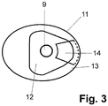
- Fig. 3 it can be seen, located in the flat portion 12 of the implant a threaded hole for the attachment of the prosthetic post.
- a groove 14 in the form of a circular segment piece is inserted in the portion 12, which prevents twisting of the crown;
- a corresponding counterpart is formed on the underside of the crown 10.
- an individually created prosthetic post 7 is used. This also engages in the groove 14 and is thus secured against rotation. If a straight, standardized philosophicalstatt 7 used, it does not engage in the groove 14, but it is only the pin-shaped part bevelled. During later cementing of the pin into the crown 10, which in turn is fastened to the implant over the groove 14 and the actual shape of the implant head 4 as far as the preparation margin 11, the latter is then connected to the crown 10 in a manner secure against rotation.
- the serving as a connection to the implant underside of the crown 10 is exactly adapted to the shape of the implant head 4 up to the preparation margin 11. It is advantageous that for the design of the edge of the bottom of the existing geometric data of the preparation margin 11 and for the production of the surface of the bottom of the inverted geometric data of the implant head 4 can be used.
- the underside of the crown 10 thus adapted is connected to the transgingival implant head 4 by cement or glue over its entire surface and free of gaps. Possibly when gluing or cementing leaking material can due to the good Accessibility of the preparation margin 11 can be easily removed.
- the smooth part of the prosthetic post 7 is cemented into the crown.
- the build-up pin 7 is screwed into the implant head 4 with the other, helical side.
- the entire surface bonding between the crown 10 and the implant absorbs a large proportion of the forces occurring during chewing.
- the connection made via the prosthetic post 7 and the flat support on the flat part 12 of the implant head 4 serve to prevent a lateral displacement and support the absorption and transmission of shear forces.
- FIGS. 4 to 6 the positions of the individual holes 17-19 required for the implant bed are shown in the upper part and the shape of the implant bed 20 in the lower part, which results from their superimposition.
- the holes are cylindrical and have the same diameter.
- Fig. 4 are two, in Fig. 5 three in a line and in Fig. 6 three in the form of an equilateral triangle spaced and tilted against each other holes 17-19 shown.
- the implant With the holes 17-19 arranged in a line and the implant bed 20 formed therefrom, the implant withstands comparatively higher rotational loads, whereas with an implant bed which is in the form of an equilateral one Triangular arranged holes 17-19 is formed, is less sensitive to tilting moments.
Landscapes
- Health & Medical Sciences (AREA)
- Oral & Maxillofacial Surgery (AREA)
- Veterinary Medicine (AREA)
- Epidemiology (AREA)
- Life Sciences & Earth Sciences (AREA)
- Animal Behavior & Ethology (AREA)
- General Health & Medical Sciences (AREA)
- Public Health (AREA)
- Dentistry (AREA)
- Orthopedic Medicine & Surgery (AREA)
- Chemical & Material Sciences (AREA)
- Ceramic Engineering (AREA)
- Plastic & Reconstructive Surgery (AREA)
- Engineering & Computer Science (AREA)
- Dental Prosthetics (AREA)
Description
- Die Erfindung betrifft ein aus einem Implantat und einer Suprastruktur bestehendes Zahnimplantatsystem.
- In Deutschland wird jährlich rund 700000 mal künstlicher Zahnersatz implantiert. Üblicherweise besteht dieser aus drei Komponenten: einer künstlichen Wurzel (Wurzelimplantat), einem Verbindungsstück, dem so genannten Abutment, und einer Suprakonstruktion wie die z. B. einer Krone oder einer Brücke.
- Zum Einsetzen des künstlichen Zahnersatzes müssten zuerst die Reste des defekten Zahnes, wie z. B. dessen Wurzeln, vollständig entfernt werden. Anschließend wird in den Kiefer eine Bohrung eingebracht bzw. in diesen ein Gewinde geschnitten und das Wurzelimplantat eingeschlagen bzw. eingeschraubt. Das Implantat wird deshalb meistens in Form eines Zylinders bzw. eines Konus hergestellt. Nach dem Einsetzen in den Kiefer muss das Implantat drei bis sechs Monate lang einheilen, d. h. fest mit dem Kiefer verwachsenen. In dieser Zeit darf das Implantat mechanisch nicht belastet werden. Nach dem Einheilen wird üblicherweise das Abutment mit dem Implantat verschraubt oder verklebt und anschließend die Suprakonstruktion auf das Abutment aufgebracht. Das Abutment trägt einen sog. Aufbaustift, welcher zur mechanischen Befestigung der Suprakonstruktion am Abutment dient.
- Dieser Aufbau bringt jedoch mehrere Nachteile mit sich. Konstruktionsbedingt entsteht zwischen dem Implantat und dem Abutment ein bakteriologisch besiedelbarer Spalt. Zahnfleischtaschen entlang dem Abutment in Richtung Knochen bilden offene Eintrittsstellen für Bakterien. Die von den Bakterien als Ausscheidungsprodukte gebildeten Säuren verhindern ein Verwachsen des Zahnfleisches mit dem Implantat/Abutment im Bereich des Spalts. Der Kieferknochen bildet sich immer entsprechend der biologischen Breite zurück; oft treten zusätzlich noch Entzündungen des Zahnfleisches und weitere Knocheneinbrüche sowie folgend weiterer Zahnfleischverlust auf. Als Konsequenz davon entstehen bakterielle Taschen, die, da sie dem Patienten selbst nicht zugänglich sind, teure und für den Patienten lästige zahnärztliche Recallmaßnahmen zur bakteriellen Taschensäuberung erforderlich machen und regelmäßig auch zum Verlust des Implantates führen. Die Durchführung der Taschensäuberung hat außerdem den Nachteil, dass das Zahnfleisch, bedingt durch diese, im Bereich oberhalb des Spalts zwischen Abutment und Implantat nicht mit dem Abutment verwachsenen kann. Hinzu kommt, dass die zwischenzeitlich unvermeidbare schlechte Zugänglichkeit der Zahnfleischtaschen eine ordentliche Mundhygiene in diesem Bereich verhindert und das Implantat infolgedessen vom Patienten als sehr unangenehm empfunden wird. Während dieser Zeit schreitet die Entzündung und Zerstörung des gesunden Gewebes weiter voran.
- Ein weiterer Nachteil ist, dass die Schraubverbindungen zwischen Wurzelimplantat und Abutment hohen mechanischen Belastungen ausgesetzt sind. Dadurch kommt es regelmäßig zu Mikrobewegungen zwischen dem Implantat und dem Abutment und nicht zuletzt zu Schraubenbrüchen mit der Folge hoher Kosten. Wird die Schraubenverbindung mit Zement oder Kleber fixiert, so kann außerdem austretendes Material zu Reizungen des Zahnfleisches führen.
- Die Wurzelimplantate sind üblicherweise als in verschiedenen Größen abgestufte, vorgefertigte, rotationssymmetrische Standardimplantate ausgeführt. Aufgrund der CE-Vorschriften für die Sterilisierung medizinischer Gegenstände darf der die Implantierung durchführende Zahnarzt während dieser die vorgefertigten Implantate nicht individuell anpassen. Aufgrund der vorgegebenen Abstufung müssen deshalb oft Kompromisse bezüglich der Größe der eingesetzten Implantate eingegangen werden. Nachteilig ist auch, dass das Implantat nicht an die durch das Einbohren des Implantatbettes in den kammförmigen Kiefer entstehenden Knochendehiszenzen angepasst werden kann. Infolgedessen weisen solche Implantate eine wesentlich geringere Knochenkontaktfläche und eine damit verbundene schlechtere Verankerung auf, als dies bei individueller Anpassung möglich wäre. Darüber hinaus werden die anatomischen Weichteilansprüche des Zahnfleisches nicht berücksichtigt. Ästhetik und Hygiene werden damit stark eingeschränkt. Die nicht kompensierten Knochendehiszenzen sind regelmäßig ursächlich für die Bildung von unerwünschten Zahnfleischtaschen. Schließlich entstehen hohe Lagerhaltungskosten, da die vorgefertigten Standardimplantate in vielen Größen und Formen vorgehalten werden müssen.
- Die Befestigung der Suprakonstruktion am Abutment mit Hilfe eines Aufbaustifts führt zu ungünstigen Kräfteverteilungen und Hebelverhältnissen, wodurch eine erhöhte Bruchgefahr besteht. Bei verschraubten Aufbaustiften treten außerdem noch nachweisbar zerstörerische Mikrobewegungen auf.
- In den letzten Jahren wurde ein erheblicher Fortschritt in der Implantattechnik erreicht; zahlreiche Entwicklungen richten sich auf die Beseitigung der o. g. Probleme.
- So wird in
DE 196 47 489 A1 vorgeschlagen, auf das Abutment an der Kontaktstelle zum enossalen Implantatkörper eine direkt aufgalvanisierte, plastisch verformbare Metallschicht aufzubringen. Damit soll die Bildung des bakteriologisch besiedelbaren Spaltes zwischen Abutment und Implantat vermieden werden. In analoger Weise wird inDE 196 47 490A1 angeregt, zwischen dem Implantat und dem Implantataufbau eine Goldscheibe einzubringen. Beide Lösungen führen zwar zu einer Minimierung des Spalts, es steht jedoch zu erwarten, dass der Kontakt zwischen Titan, Gold und Zahnfleisch sowie Speichel irritative chemische Reaktionen hervorruft. Eine bakteriologische Besiedlung ist zudem nicht auszuschließen. - In
WO2004/058096 A1 wird ein Abutment beschrieben, das mit einer axialen durchgängigen Bohrung versehen ist. Es ist vorgesehen, das Abutment mit dem Implantat zu verschrauben, wobei die Verschraubung zusätzlich mit Zement fixiert wird. Die durchgängige Bohrung dient dazu, dass während des Verklebens überschüssiger Zement durch diese herausgedrückt wird und sich auf dem flachen Kopf des Implantats sammelt. Von dem Kopf kann der Zement einfach entfernt werden. Damit können Zahnfleischentzündungen durch an anderen Stellen austretenden Zement verhindert werden. -
DE 10 2005 027 402 A1 offenbart ein Verfahren zur Herstellung eines individualisierten Ersatzzahns, der über einen Verbindungszapfen in einem eingeheilten Implantat aufgenommen werden kann. Um den Aufwand bei der Erstellung von Zahnersatz zu verringern, wird vorgeschlagen, den Ersatzzahn einteilig herzustellen. Damit kann auf ein separates Abutment verzichtet werden. Hierdurch wird unbestritten eine Vereinfachung erzielt, das Problem des bakteriologisch besiedelbaren Spalts bleibt jedoch bestehen. - In
EP 0 967 931 B1 wird ein Zahnimplantat vorgestellt, das aus einem konischen Schaftabschnitt und einem divergenten Kopfabschnitt besteht, wobei beide Abschnitte integral ausgebildet bzw. als ein verbundenes Teil ausgeführt sind. Das Zahnimplantatsystem umfasst außerdem ein zum Zahnimplantat passendes Abutment, das zum Stützen eines Zahnersatzes/einer Krone dient. Das Abutment wird mit Hilfe einer Schraube in den konischen Schaftabschnitt des Zahnimplantats eingeschraubt. - Durch die einteilige bzw. integrale Ausführung von Schaft- und Kopfabschnitt wird zwar ein Mikrospalt im enossalen Bereich vermieden, die Ausbildung eines bakteriologisch besiedelbaren Spaltes zwischen Schaft-/Kopfabschnitt und Abutment im gingivalen Bereich ist jedoch unvermeidlich.
- In
EP 0 891 163 B1 wird ein dentales Stützlager beschrieben, das aus einem Implantat und einem Abutment aufgebaut ist. Die Oberkante des Abutments und entsprechend die Unterkante der daran befestigten Krone sind beim Austritt aus dem Zahnfleisch an das entsprechende Austrittsprofil und die Größen des zu ersetzenden Zahnes angepasst. - Dadurch, dass die Grenze zwischen Abutment und Krone an den Verlauf des Zahnfleisches angepasst wird, werden ästhetische und funktionelle Vorteile gegenüber rotationssymmetrischen Lösungen erreicht. Die Grenze zwischen Abutment und Krone liegt jedoch genau auf der Höhe des Zahnfleischsaums oder darüber. Da sich das Zahnfleisch im Laufe der Zeit üblicherweise zurückbildet, lässt sich nicht vermeiden, dass nach einiger Zeit das metallische Abutment über den Zahnfleischsaum reicht und sichtbar wird.
- Alternativ zu dem vorstehend beschriebenen Zahnersatz ist es allgemeiner Stand der Technik, ein rotationssymmetrisches Implantat zu verwenden, bei dem die enossalen Teile des Implantats, das Abutment und ggf. der Aufbaustift aus einem Stück gefertigt oder zumindest nahtlos gefügt sind (s.
DE 10 2005 001 185 A1 ). - Derartige Implantate vermeiden demgemäß von vornherein einen Spalt im Grenzbereich zwischen Kieferknochen und Zahnfleisch, das Zahnfleisch kann mit dem Implantat problemlos verwachsen, da Mikrobewegungen vermieden werden. Trotzdem konnten sich diese Implantate aus mehreren wesentlichen Gründen nicht durchsetzen. Ein Grund ist, dass der Aufbaustift konstruktionsbedingt in den Mundraum ragt. Dies führt unweigerlich zu mechanischen Belastungen des Implantats während des Einwachsens und daraus folgend häufig zum Fehlschlagen der Implantierung. Ein weiterer Grund ist, dass aufgrund der Rotationssymmetrie des Implantats dieses am Übergang von Krone zum Zahnfleisch sichtbar bleibt, was insbesondere bei der Verwendung von Titan aus ästhetischen Gründen nicht akzeptabel ist. Besonders nachteilig ist, dass die durch die Bohrung in den kammförmigen Kieferknochen verursachten vestibulären/buccalen und palatinalen/lingualen Knochendehiszenzen von der Form des Implantates nicht berücksichtigt werden.
- Weitere Zahnimplantate bzw. Zahnimplantatsysteme mit rotationssymmetrischem Querschnitt des unteren enossalen Bereichs und/oder Gewinde zum Einschrauben in den Knochen sind aus
WO 2005/065571 A ,US 2006/252009 A1 ,DE 10 2004 055 831 A1 ,US 5 759 036 A ,WO 2006/084346 A ,EP 1 013 236 A undRU 2 146 113 C1 - Auch beschreibt
US 2004/0185419 A1 ein einstückiges Implantat mit einem Gewinde im enossalen Bereich. - Ein einstückiges Implantat aus Zirkonoxid, dessen transgingivaler Bereich erst im implantierten Zustand auf die benötigte Form geschliffen wird, ist in
WO 01/34056 A1 - Aus
GB-A-1 431 563 -
DE 195 13 881 A1 beschreibt ein Verfahren zur Herstellung eines Implantats, bei dem ein Rohling entsprechend der natürlichen Kavität des Zahnwurzelbereichs durch Kopierfräsen nachgebildet wird. -
US2006/0292523 A1 offenbart ein Zahnimplantatsystem mit einem Implantat und einer darauf aufgebauten Suprakonstruktion. Das Implantat weist einen mit Rillen strukturierten unteren enossalen Bereich, einen sich nach oben hin aufweitenden oberen enossalen Bereich mit aufgerauter Oberfläche, einen transgingivalen Bereich mit glatter Wandfläche und einen transgingivalen hexagonalen Implantatkopf auf. Die Grenze zwischen dem aufgerauten oberen enossalen Bereich und dem glatten transgingivalen Bereich ist krumm und die koronale Kante des transgingivalen Bereichs ist auch krumm. In einem Querschnitt senkrecht zur Implantatsachse hat der transgingivale Bereich eine nichtrotationssymmetrische Form. - Aufgabe der Erfindung ist es, die Nachteile des Standes der Technik zu beseitigen. Insbesondere soll ein ästhetisch ansprechendes, am Zahnfleischsaum unsichtbares Zahnimplantatsystem geschaffen werden, das ein gutes Verwachsen des Zahnfleisches im gingivalen Bereich ermöglicht und eine mechanisch stabile und langlebige Verbindung eines Zahnaufbaus mit dem Kieferknochen gewährleistet.
- Diese Aufgabe wird erfindungsgemäß durch die kennzeichnenden Merkmale des Anspruchs 1 gelöst; weitere vorteilhafte Ausführungen ergeben sich aus den Ansprüchen 2 bis 10.
- Ausgegangen wird von einem Zahnimplantatsystem, das aus einem Implantat und einer darauf aufgebauten Suprakonstruktion besteht. Das Implantat setzt sich aus einem wabenförmig strukturierten unteren enossalen Bereich, einem sich nach oben hin aufweitenden oberen enossalen Bereich mit aufgerauter Oberfläche, einem transgingivalen Bereich mit glatter Wandfläche und einem transgingivalen Implantatkopf zusammen. Alle diese Bereiche schließen naht- und spaltlos aneinander an.
- Der untere enossale Bereich ist üblicherweise rotationssymmetrisch zylindrisch/konisch, kombiniert rotationssymmetrisch zylindrisch/konisch, rotationssymmetrisch stufenförmig zylindrische/konisch oder kombiniert rotationssymmetrisch stufenförmig zylindrisch/konisch geformt. Bevorzugt ist er mit einer Wabenstruktur mit Spitzen an den Eckpunkten versehen, die für ein gutes Einwachsverhalten in den Kieferknochen bekannt ist. Nach Maßgabe der Erfindung weist der obere enossale Bereich jeweils in vestibulärer/bukkaler Richtung und in palatinaler/lingualer Richtung eine Verkürzung auf. Entsprechend ist der obere enossale Bereich, an den Stellen, an denen er seitlich am Kieferkamm anliegt, höher ausgeführt. Dadurch wird das Implantat genau an die patientenspezifische Kammform des Kiefers angepasst und infolgedessen werden die durch die Bohrung des Implantatbettes entstehenden Knochendehiszenzen vollständig vom Implantat berücksichtigt. Dadurch dass sich der obere enossale Bereich nach obenhin aufweitet, wird bei der Implantierung eine größere Knochenkontaktfläche und folglich ein besserer Halt des Implantats im Kieferknochen erreicht.
- Der glatte transgingivale Bereich ist entsprechend der Kavität im Zahnfleisch des Patienten geformt. Bedingt durch diese anatomische Ausformung weist der transgingivale Bereich bei jedem Längs- und jedem Querschnitt eine andere Form als bei dem entsprechenden davor oder danach liegenden Längs- bzw. Querschnitt auf. Der transgingivale Bereich wird nach oben durch einen individuell geformten, dreidimensional differenziert in Höhe, Breite und Tiefe gestalteten transgingivalen Implantatkopf begrenzt, d. h. der Implantatkopf bildet die "Deckelfläche" des Implantats. Er weist ebenfalls bei jedem Längsschnitt und jedem Querschnitt eine andere Form als bei dem davor oder danach liegenden Längsschnitt bzw. Querschnitt auf. Die so durch den transgingivalen Bereich und den transgingivalen Implantatkopf gebildete, umlaufende Kante entspricht hierbei der Präparationsgrenze und ist so geformt, dass diese nach erfolgter Implantierung knapp, typischerweise 1 mm, unterhalb des Zahnfleischsaums verlaufen wird.
- Der transgingivale Implantatkopf weist in seiner Mitte einen flachen Bereich auf. Dieser ist umgeben von einem steiler abfallenden Teilbereich, der den flachen Teilbereich mit dem transgingivalen Bereich verbindet. Dabei ist das durch den flachen Bereich des Implantatkopfs gebildete Plateau genau so hoch angeordnet, dass es in approximaler Richtung auf Höhe der oberen Zahnfleischbegrenzung liegt.
- Erfindungsgemäß, ist der steilere Teilbereich des Implantatkopfes in vestibulärer/buccaler Richtung sowie in palatinaler/lingualer Richtung länger und steiler als in den übrigen Richtungen.
- Somit wird der obere enossale Bereich an die patientenspezifische Kammform des Kiefers angepasst.
- Auf die gesamte Fläche des Implantatkopfes ist eine Suprakonstruktion mit ihrer Unterseite, die der Form des Implantatkopfes angepasst ist, aufgeklebt oder - zementiert. Diese Verbindung nimmt einen Großteil der zwischen Implantat und Suprakonstruktion wirkenden Kräfte auf. Zur Vermeidung einer seitlichen Verschiebung und um eine weitere mechanische Stabilisierung zu erreichen, ist zusätzlich ein Aufbaustift ungefähr im Zentrum der Präparationsfläche in den transgingivalen Bereich des Implantats eingeschraubt und auf der anderen Seite mit der Suprakonstruktion verbunden. Die Basalfläche des Aufbaustifts liegt auf dem flachen Teil des transgingivalen Implantatkopfes auf und wirkt als kraftkompensierender Kippmeider und als kraftaufnehmender und übertragender Teil.
- Das Implantat ist vorteilhafterweise aus einem Stück (Rohling) hergestellt. Als medizintechnisch bewährte Materialien bieten sich hierbei Titan und Zirkonoxid sowie alle zur Zahnimplantation geeigneten Materialien an.
- Das erfindungsgemäße Zahnimplantatsystem zeigt gegenüber den üblicherweise verwendeten Systemen mehrere Vorteile.
- Wesentlicher Vorteil des Implantatsystems ist, dass dieses ohne Abutment auskommt, wodurch ein bakteriologisch besiedelbarer Spalt im Grenzbereich zwischen Kieferknochen und Zahnfleisch von vornherein vermieden wird. Da sich die Präparationsgrenze knapp unterhalb des Zahnfleischsaums befindet, ist diese dem Patienten zugänglich und kann von diesem bequem gereinigt werden. Die Notwendigkeit von zahnärztlichen Taschensäuberungen entfällt. Außerdem kann das Implantat schon während der Einwachsphase des enossalen Bereichs in den Kieferknochen gleichzeitig im transgingivalen Bereich mit dem Zahnfleisch verwachsen. Dies ist besonders vorteilhaft, wenn das Zahnfleisch durch das Vorgehen zur Implantation noch "frisch und blutig" ist. Da keine Notwendigkeit zur Taschensäuberung besteht, muss das an das Implantat gewachsene Zahnfleisch auch nicht später wieder gelöst werden. Dies hat zur Folge, dass teure und für den Patienten lästige Recallmaßnahmen vermieden werden und außerdem, da sich nicht wie sonst üblich, Zahnfleischtaschen bilden, das Implantat vom Patienten kaum noch als Fremdkörper empfunden wird, da die Maßnahmen zur Mundhygiene in diesem Bereich einfach und vor allem sicher zu bewältigen sind.
- Durch das Wegfallen der Verschraubung zwischen Implantat und Abutment, werden die sonst konstruktiv bedingten Mikrobewegungen zwischen Implantat und Abutment, die häufig die Ursache für Schraubenbrüche aber auch für eine Rückbildung des umgebenden Kieferknochenabschnitts und folgend auch die Ursache für die Rückbildung des über dem Kieferknochen befindlichen und eben durch den Knochen unterstützten und stabilisierten Zahnfleisches sind, ausgeschlossen.
- Durch die individuelle, an die Anatomie des Patienten angepasste Größe und Form des unteren enossalen Bereichs, wird eine größtmögliche Knochenkontaktfläche erreicht. Durch die sich nach oben aufweitende Form sowie die genaue Anpassung des oberen enossalen Bereichs an die Kammform des Kieferknochens und die damit verbundene vollständige Anpassung an die durch Implantatbettbohrung entstehenden Knochendehiszenzen, wird gleichermaßen eine große Auflagefläche im oberen Bereich des Kieferknochens gewährleistet. Bedingt durch seine strukturierte bzw. raue Oberfläche kann der enossale Bereich des Implantats mit dem Kieferknochen zügig und sicher verwachsen.
- Die einzige Verbindungsstelle des Zahnimplantatsystems ist so gewählt, dass sie einerseits vom Patienten selbst gereinigt werden kann, andererseits jedoch mechanische Belastungen während der Einwachsphase durch mechanischen Kontakt, wie z. B. mit anderen Zähnen, weitgehend vermieden werden.
- Im Gegensatz zu den bislang verwendeten Zahnimplantatsystemen, bei denen die mechanische Verbindung zwischen Implantat und Suprastruktur hauptsächlich über ein Abutment/einen Aufbaustift erfolgt, nimmt bei dem erfindungsgemäßen System eine großflächige stoffschlüssige Verbindung, gebildet durch Kleber oder Zement zwischen Implantatkopf -und Unterseite der Suprastruktur, die mechanischen Belastungen auf. Der verwendete Prothetikpfosten hat eine unterstützende Funktion, verhindert ein seitliches Verschieben während des Einbringens der Suprastruktur, und fungiert durch die basale Auflage auf dem flachen Teil des transgingivalen Implantatkopfes bei seitlich einfallenden Kräften als kraftaufnehmendes Element.
- Es ist erfindungsgemäß auch vorgesehen, dass der untere und obere enossale Bereich des Zahnimplantatsystems nichtrotationssymmetrisch ausgeformt ist, wobei seine Geometrie der Überlagerung von mindestens zwei rotationssymmetrischen geometrischen Körpern entspricht, deren Symmetrieachsen zueinander parallel versetzt oder derart zueinander verkippt sind, dass sie sich zumindest im unteren enossalen Bereich schneiden. Die geometrischen Körper überlappen sich immer zumindest im oberen enossalen Bereich, sodass dort nichtrotationssymmetrische geschlossene Querschnittsflächen gebildet werden. Der untere enossale Bereich kann zahnwurzelartig ausgebildet sein oder gleichfalls geschlossene Querschnittsflächen aufweisen.
- Aufgrund der nichtrotationssymmetrischen Form des enossalen Bereichs bildet das eingesetzte Implantat mit den Kieferknochen ein Widerlager, das vergleichsweise hohen Dreh- und Kippbelastungen standhält. Zudem ermöglicht diese Ausgestaltung die eindeutige Positionierung und Fixierung des Implantates im Kieferknochen.
- Für die Teile des oberen und unteren enossalen Bereichs, die geschlossene Querschnittsflächen aufweisen, sind bevorzugt Geometrien gewählt, die der Überlagerung von zylindrischen geometrischen Körpern mit kegelförmigen Spitzen entsprechen. Die Zylinder können dieselben aber auch nicht dieselben Radien haben. Die Symmetrieachsen der Körper sind so angeordnet, dass sie sich zumindest im unteren enossalen Bereich schneiden. Die Kippwinkel der Symmetrieachsen zueinander betragen üblicherweise 1° bis 45°.
- Für zahnwurzelartig ausgebildete Teile des unteren enossalen Bereichs sind bevorzugt Geometrien gewählt, die der Überlagerung von parallel angeordneten, konischen geometrischen Körpern entsprechen.
- Das Verfahren zur Herstellung eines Zahnimplantatsystems und zu dessen Einbringung in den Kiefer bzw. Mundraum des Patienten umfasst die folgenden Schritte:
- Zuerst werden die Kieferform, und die Form des Zahnfleisches des zu behandelnden Patienten mit CT (Computertomographie), DVT (Volumentomographie) oder alternativ dazu mit OPG aufgenommen.
- An einem Rohling, aus dem das gesamte Implantat hergestellt werden soll, wird zuerst anhand der ermittelten anatomischen Diagnosedaten der enossale Abschnitt mithilfe der CAD/CAM-Technik geformt. Dieser Abschnitt ist rotationssymmetrisch zylindrisch/konisch, kombiniert rotationssymmetrisch zylindrischen/konisch, rotationssymmetrisch stufenförmig zylindrisch/ konisch oder kombiniert rotationssymmetrisch stufenförmig zylindrisch/konisch geformt. Um ein gutes Einwachsens in den Knochen zu ermöglichen, ist der enossale Abschnitt mit einer Struktur versehen. Vorzugsweise wird hierbei eine bewährte Wabenstruktur, die Spitzen an ihren Eckpunkten aufweist, gewählt.
- Anschließend wird angrenzend an den enossalen Abschnitt entsprechend den anatomischen Diagnosedaten ein weiterer enossaler Bereich durch CAD/CAM geformt. Zur individuellen Anpassung an die Kammform des Kiefers wird hierbei in vestibulärer/bukkaler Richtung eine stärkere und in palatinaler/lingualer Richtung eine geringere Verkürzung eingearbeitet. Auf diese Weise werden später bei der Bohrung des Implantatbettes entstehende Knochendehiszenzen von der Implantatform vollständig berücksichtigt.
- Danach wird ein transgingivaler Bereich anhand der ermittelten anatomischen Diagnosedaten durch manuelle Bearbeitung oder ggf. durch CAD/CAM hergestellt. Die individuelle Ausformung, führt dazu, dass in jedem Fall der transgingivale Bereich bei jedem Längsschnitt und jedem Querschnitt eine andere Form als bei dem entsprechenden davor oder danach liegenden Längsschnitt bzw. Querschnitt aufweist.
- Daraufhin wird der den transgingivalen Bereich nach oben begrenzende transgingivale Implantatkopf durch manuelle Bearbeitung oder ggf. durch CAD/CAM hergestellt. Der Implantatkopf wird nach den diagnostischen Vermessungsdaten der Form sowie des Randverlaufs der Kavität in der Gingiva so ausgeformt, dass die durch die Präparationsfläche und den transgingivalen Bereich gebildete Kante nach der Implantation unterhalb des Zahnfleischsaums verläuft. Ungefähr in der Mitte des Implantatkopfes wird ein flacher Teilbereich und diesen umgebend ein steiler abfallender Teilbereich geformt. Durch den steileren Teilbereich werden der flachere Teilbereich und der transgingivale Bereich miteinander verbunden. Außerdem ist eine Gewindebohrung für die Aufnahme eines Aufnahmepfostens in den flachen Teilbereich des Implantatkopfes eingebracht.
- Als nächstes wird der transgingivale Bereich und der transgingivale Implantatkopf geglättet. Das Glätten erfolgt vorzugsweise durch mechanisches manuelles Polieren bzw. durch CAD/CAM. Danach erfolgt das Aufrauen der Oberfläche des gesamten enossalen Bereiches des Implantates mittels geeigneter Techniken.
- Als nächster Schritt erfolgt ein stufenweises Heranführen des Durchmessers des zu bohrenden Implantatbettes. Dazu wird als erstes in den Kieferknochen das Implantatbett stufenweise mit entsprechenden Bohrern, beginnend bei einem ca. 1 mm kleineren bis hin zu einem 0,5 mm kleineren Durchmesser als der untere enossale Bereich des Implantates, eingebohrt. Anschließend wird anhand der Bohrung oder durch weitere Testverfahren die Härte bzw. Qualität des Knochens ermittelt. Da sich die Knochenqualität und -härte während der Erweiterung eines Bohrloches drastisch ändern können, wird der Durchmesser des Bohrloches stufenweise in Schritten von 0,1 mm vergrößert. Mit jeder erfolgten Bohrung wird die Knochenqualität neu ermittelt und der Durchmesser der Bohrung mit Hilfe von geeigneten Messinstrumenten und Verfahren geprüft. Die Bohrung wird solange schrittweise vergrößert, bis die Knochenqualität und die Größe des Bohrloches optimal aufeinander abgestimmt sind.
- Danach erfolgt ein Einsetzen des Implantats durch Einklopfen des enossalen Bereichs in das Bohrloch.
- Anschließend heilt das Implantat über einen Zeitraum von 3 bis 6 Monaten in den Kiefer ein.
- In einem weiteren Schritt wird ein geeigneter Aufbaustift gewählt bzw. hergestellt. Zeigt das Implantat keine Angulation, so kann ein gerader, vorkonfektionierter Aufbaustift, der auf einer Seite ein Gewinde zum Einschrauben in den transgingivalen Implantatkopf und auf der gegenüberliegenden Seite einen Stift zur Befestigung an der Suprastruktur trägt, verwendet werden. Beim Auftreten einer Angulation wird eine Hülse aus ausbrennbarem Kunststoff entweder subtraktiv durch mechanischen Abtrag oder additiv durch Aufbringen von Wachs individuell geformt. Das so erzeugte Modell wird anschließend nach der Gussmethode des verlorenen Modells aus Metall gegossen, wobei eine Schraube in Längsrichtung durch die Hülse geführt wird und die Stifthülse am transgingivalen Implantatkopf mittels dieser Schraube verschraubt wird. Alternativ dazu kann der Aufbaustift auch komplett mittels CAD/CAM hergestellt werden.
- Des Weiteren wird eine individuell an die Diagnosedaten des Patienten angepasste Suprastruktur, wie z. B. eine Krone oder Brücke, hergestellt. Dabei können für die Unterseite der Suprastruktur, die als Anschlussfläche an das Implantat dient, für die Formung des Randes die bereits vorhandenen geometrischen Daten der Präparationsgrenze und für die Formung der Topologie der Fläche der Unterseite die invertierten Daten der Fläche des Implantatkopfes verwendet werden.
- Nach erfolgter Einheilung des Implantats wird der Aufbaustift in die auf dem Implantatkopf befindliche Gewindebohrung eingeschraubt.
- Anschließend wird die entsprechend der Form des Implantatkopfes geformte Unterseite der Suprastruktur auf die gesamte Fläche des Implantatkopfes aufgeklebt bzw. aufzementiert. Im selben Schritt wird der Aufbaustift mit der Suprastruktur mechanisch verbunden.
- Die Erfindung wird nachfolgend anhand von vier Ausführungsbeispielen näher erläutert; hierzu zeigen in schematischer Darstellung zunächst:
- Fig. 1:
- ein Zahnimplantat mit Krone (Schnitt; Ansicht von vestibulär)
- Fig. 2:
- ein Zahnimplantat (Schnitt; Ansicht von approximal)
- Fig. 3:
- einen Implantatkopf in Draufsicht
- In
Fig. 1 ist ein einteiliges Zahnimplantat aus Titan mit einer daran befestigten Krone 10 als Querschnitt mit palatinaler Blickrichtung dargestellt. Zur besseren Verdeutlichung zeigtFig. 2 ein Implantat mit prothetischem Aufbaustift 7 im Querschnitt, jedoch mit einer Blickrichtung in Richtung des Kieferknochens. - Das Implantat besteht aus einem unteren enossalen Bereich 1, einem oberen enossalen Bereich 2, einem transgingivalen Bereich 3 und einem transgingivalen Implantatkopf 4. Zur Herstellung des Implantats werden Bereich 1 und Bereich 2 mit Hilfe von CAD/CAM sowie Bereich 3 und der transgingivale Implantatkopf 4 mit Hilfe von CAD/CAM oder durch manuelle Bearbeitung aus einem Rohling geformt.
- Der tief im Kieferknochen sitzende, untere enossale Bereich 1 weist ein Wabenmuster auf, wobei sich jeweils in den Ecken der Waben Spitzen befinden. Diese bewährte Struktur ermöglicht ein optimales Einwachsen des Implantats.
- An den unteren enossalen Bereich 1 schließt sich der obere enossale Bereich 2 an, der so ausgeformt ist, dass sein oberer Rand genau bis zur Oberkante des kammförmigen Kieferknochens 5 reicht. Um dies zu erreichen wird üblicherweise der obere enossale Bereich 2 auf der vestibulären Seite wesentlich kürzer und auf der palatinalen Seite etwas kürzer ausgeführt als an den restlichen Stellen. Es gibt jedoch auch Fälle, in denen zur genauen Anpassung an die Kammform des Kiefers die palatinale Seite kürzer ausgeführt werden muss als die vestibuläre. Knochendehiszenzen, die durch das Bohren des Implantatbettes entstehen, werden durch diese spezielle Formgebung vollständig anatomisch erfasst. Um außerdem eine breitere Auflagefläche und eine bessere Kräfteverteilung im Knochen 5 zu erreichen, wird der obere enossale Bereich 2 nach oben hin breiter (Trichterform). Aufgrund seiner aufgerauten Oberfläche kann der Bereich 2 auch mit dem Kieferknochen 5 verwachsen.
- Dem Bereich 2 folgt der glatt polierte transgingivale Bereich 3. Dieser Bereich ist derart geformt, dass er umlaufend bis ca. 1 mm unterhalb des Zahnfleischsaums reicht, was in etwa der Tiefe entspricht, bis zu welcher auch bei einem gesunden Zahn das Zahnfleisch nicht mit dem Zahn verwachsen ist, sondern lediglich lose anliegt. Die glatt polierte Titanoberfläche ermöglicht hierbei ein gutes und reizfreies Anwachsen des Zahnfleisches 6.
- An das Ende des transgingivalen Bereichs 3, welches gleichzeitig die Präparationsgrenze 11 bildet, schließt sich der transgingivale Implantatkopf 4 an. Der Implantatkopf 4 besteht aus einem flachen, nahezu ebenen inneren Teilbereich 12 und einen diesen umgebenden, steiler ausgeformten Teilbereich 13; die Bereiche 12/13 können (hier nicht dargestellt) auch übergangslos, etwa in balliger Form, zusammengefasst sein. Der steilere Teilbereich 13 verbindet den ebenen Teilbereich 12 mit dem transgingivalen Bereich 3. Bedingt durch die Anpassung des Implantats an die Kammform des Kieferknochens 5 ist der Teilbereich 13 in vestibulärer/bukkaler Richtung meistens wesentlich länger und steiler und in palatinaler/lingualer Richtung etwas länger und steiler als an den restlichen Stellen.
- Wie aus
Fig. 3 ersichtlich ist, befindet sich im flachen Teilbereich 12 des Implantats eine Gewindebohrung für die Befestigung des prothetischen Aufbaustifts. Außerdem ist im Teilbereich 12 eine Nut 14 in Form eines Kreissegmentstückes eingelassen, die ein Verdrehen der Krone verhindert; hierfür ist auf der Unterseite der Krone 10 ein entsprechendes Gegenstück ausgeformt. Wie inFig. 2 zu sehen ist, wird ein individuell erstellter prothetischer Aufbaustift 7 verwendet. Dieser greift ebenfalls in die Nut 14 ein und ist somit auch gegen Verdrehen gesichert. Wird ein gerader, standardisierter Aufbaustift 7 verwendet, so greift dieser nicht in die Nut 14 ein, sondern es wird lediglich dessen stiftförmiger Teil angeschrägt. Beim später erfolgenden Einzementieren des Stiftes in die Krone 10, die ihrerseits über die Nut 14 und die eigentliche Form des Implantatkopfes 4 bis hin zur Präparationsgrenze 11 verdrehsicher am Implantat befestigt ist, wird dieser dann verdrehsicher mit der Krone 10 verbunden. - Die als Anschluss an das Implantat dienende Unterseite der Krone 10 ist genau an die Form des Implantatkopfes 4 bis hin zur Präparationsgrenze 11 angepasst. Dabei ist es von Vorteil, dass für die Gestaltung des Randes der Unterseite die bereits vorhandenen geometrischen Daten der Präparationsgrenze 11 und für die Herstellung der Fläche der Unterseite die invertierten geometrischen Daten des Implantatkopfes 4 verwendet werden können.
- Die derart angepasste Unterseite der Krone 10 ist vollflächig und spaltfrei mit dem transgingivalen Implantatkopf 4 durch Zement bzw. Kleber verbunden. Eventuell beim Verkleben oder Zementieren austretendes Material kann aufgrund der guten Zugänglichkeit der Präparationsgrenze 11 unkompliziert entfernt werden. Zusätzlich ist in die Krone der glatte Teil des prothetischen Aufbaustifts 7 einzementiert. Der Aufbaustift 7 ist mit der anderen, schraubenförmigen Seite in den Implantatkopf 4 eingeschraubt. Hierbei nimmt die ganzflächige Verklebung zwischen Krone 10 und Implantat einen großen Anteil der beim Kauen auftretenden Kräfte auf. Die über den Prothetikposten 7 hergestellte Verbindung und flächige Auflage auf dem flachen Teil 12 des Implantatkopfes 4 dient dem Verhindern einer seitlichen Verschiebung und unterstützend der Aufnahme und Weiterleitung von Scherkräften.
-
Fig. 4 bis 7 zeigen nämlich das Einbringen der Bohrungen in den Kieferkamm, die die Form des Implantatbettes erzeugen und letztlich die Geometrie des enossalen Bereichs des Zahnimplantatsystems bestimmen. Im Einzelnen sind dargestellt: - Fig. 4:
- das Einbringen zweier zueinander versetzter Bohrungen und das dadurch entstandene (8-förmige) Implantatbett in Draufsicht;
- Fig. 5:
- das Einbringen dreier in Form einer Linie beabstandeter und gegeneinander verkippter (nicht ersichtlich) Bohrungen in Draufsicht;
- Fig. 6:
- das Einbringen dreier in Form eines gleichseitigen Dreiecks beabstandeter und gegeneinander verkippter (nicht ersichtlich) Bohrungen in Draufsicht;
- Fig. 7:
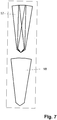
- das Einbringen dreier in einer Linie beabstandeter und gegeneinander verkippter Bohrungen in seitlicher Ansicht.
- In den
Figuren 4 bis 6 sind im oberen Teil die Positionen der einzelnen für das Implantatbett erforderlichen Bohrungen 17-19 und im unteren Teil die Form des Implantatbettes 20 dargestellt, das sich durch deren Überlagerung ergibt. Die Bohrungen sind zylindrisch und haben denselben Durchmesser. - In
Fig. 4 sind zwei, inFig. 5 drei in einer Linie und inFig. 6 drei in Form eines gleichseitigen Dreiecks beabstandete und gegeneinander verkippte Bohrungen 17-19 dargestellt. Bei den in einer Linie angeordneten Bohrungen 17-19 und dem daraus geformten Implantatbett 20 hält das Implantat vergleichsweise höheren Drehbelastungen stand, während es bei einem Implantatbett, das in Form eines gleichseitigen Dreiecks angeordneten Bohrungen 17-19 gebildet ist, unempfindlicher gegenüber Kippmomenten ist. - Aus
Fig. 7 ist ersichtlich, dass sich einerseits die Spitzen der Bohrungen 17-19 im untersten Punkt des Implantatbetts 20 treffen und andererseits die Bohrungen 17-19 sich über die gesamte Länge des Implantatbetts überschneiden. Damit wird eine konische Form des Implantatbettes 20 bzw. des unteren enossalen Bereichs erreicht, bei der jede Querschnittsfläche zusammenhängend ist. -
- 1
- unterer enossaler Bereich
- 2
- oberer enossaler Bereich
- 3
- transgingivaler Bereich
- 4
- transgingivaler Implantatkopf
- 5
- Kieferknochen
- 6
- Gingiva
- 7
- prothetischer Aufbaustift
- 8
- Gewinde
- 9
- Gewindebohrung
- 10
- Krone
- 11
- Präparationsgrenze/Kante
- 12
- flacher Teilbereich
- 13
- steilerer Teilbereich
- 14
- Nut
- 15
- vestibuläre/buccale Verkürzung
- 16
- palatinale/linguale Verkürzung
- 17-19
- Bohrung
- 20
- Implantatbett
Claims (10)
- Zahnimplantatsystem bestehend aus einem Implantat und einer darauf aufgebauten Suprakonstruktion, wobei sich das Implantat aus einem wabenförmig strukturierten unteren enossalen Bereich (1), einem sich nach oben hin aufweitenden oberen enossalen Bereich (2) mit aufgerauter Oberfläche, einem transgingivalen Bereich (3) mit glatter Wandfläche und einem transgingivalen Implantatkopf (4) zusammensetzt und alle Bereiche naht- und spaltlos aneinander anschließen,- wobei der obere enossale Bereich (2) jeweils in vestibulärer/buccaler Richtung eine Verkürzung (15) und in palatinaler/lingualer Richtung eine Verkürzung (16) aufweist, sodass der obere enossale Bereich (2), an den Stellen, an denen er seitlich am Kieferkamm anliegt, höher ausgeführt ist,- und der transgingivale Bereich (3) bei jedem Längsschnitt und jedem Querschnitt eine andere Form aufweist als bei jedem davor oder danach liegenden Längsschnitt bzw. Querschnitt,
und der transgingivale Bereich (3) nach oben durch einen dreidimensional in Höhe, Breite und Tiefe differenziert geformten transgingivalen Implantatkopf (4) begrenzt wird, wobei eine umlaufende Kante (11), durch das Aneinandergrenzen des Implantatkopfes (4) und des transgingivalen Bereiches (3) gebildet ist, sodass nach erfolgter Implantierung die umlaufende Kante (11) unterhalb des Zahnfleischsaums verlaufen wird,- wobei der Implantatkopf (4) ungefähr in seiner Mitte einen flachen Teilbereich (12) aufweist, an den sich diesen umgebend ein steiler abfallender Teilbereich (13) anschließt, durch welchen der flache Teilbereich (12) und der transgingivale Bereich (3) miteinander verbunden sind,- wobei der steilere Teilbereich (13) des Implantatkopfes (4) in vestibulärer/buccaler Richtung sowie in palatinaler/lingualer Richtung länger und steiler als in den übrigen Richtungen ist. - Zahnimplantatsystem nach Anspruch 1, dadurch gekennzeichnet, dass das Implantat, bestehend aus dem unteren enossalen Bereich (1), dem oberen enossalen Bereich (2), dem transgingivalen Bereich (3) und dem transgingivalen Implantatkopf (4), einteilig ausgeführt ist.
- Zahnimplantatsystem nach Anspruch 1 und 2, dadurch gekennzeichnet, dass der untere (1) und der obere (2) enossale Bereich des Implantats eine nichtrotationssymmetrische Geometrie aufweisen, die der Überlagerung von mindestens zwei rotationssymmetrischen geometrischen Körpern entspricht, deren Symmetrieachsen parallel verlaufen oder zueinander verkippt sind, dass sie sich zumindest im unteren enossalen Bereich schneiden, wobei sich die geometrischen Körper zumindest im oberen enossalen Bereich überlappen.
- Zahnimplantatsystem nach Anspruch 3 dadurch gekennzeichnet, dass die Geometrie des oberen und unteren enossalen Bereichs des Implantats der Überlagerung von geometrischen Körpern, die die Form eines Zylinders mit einer kegelförmigen Spitze haben, entspricht, wobei sich die Symmetrieachsen der Zylinder im unteren Ende des unteren enossalen Bereichs schneiden.
- Zahnimplantatsystem nach Anspruch 3 dadurch gekennzeichnet, dass die Geometrie des oberen und unteren enossalen Bereichs des Implantats der Überlagerung von geometrischen Körpern, die die Form eines Zylinders mit einer kegelförmigen Spitze haben, entspricht, wobei die Symmetrieachsen der Zylinder parallel verlaufen und in Form eines n-Ecks beabstandet sind.
- Zahnimplantatssystem nach den Ansprüchen 1 bis 5, dadurch gekennzeichnet, dass das Implantat aus Titan besteht.
- Zahnimplantatssystem nach den Ansprüchen 1 bis 5, dadurch gekennzeichnet, dass das Implantat aus Zirkonoxid besteht.
- Zahnimplantatsystem nach den Ansprüchen 1 bis 7, dadurch gekennzeichnet, dass der transgingivale Implantatkopf (4) eine Aussparung (14), welche als Sicherung gegen ein Verdrehen der Suprakonstruktion (10) dient, aufweist.
- Zahnimplantatsystem nach Anspruch 8, dadurch gekennzeichnet, dass die Aussparung (14) die Form eines Kreissegments hat.
- Zahnimplantatsystem nach den Ansprüchen 8 und 9, dadurch gekennzeichnet, dass ein prothetischer Aufbaustift (7) in die Aussparung (14) eingreift.
Priority Applications (1)
| Application Number | Priority Date | Filing Date | Title |
|---|---|---|---|
| PL08757938T PL2142136T3 (pl) | 2007-04-17 | 2008-04-15 | System implantacji zęba |
Applications Claiming Priority (4)
| Application Number | Priority Date | Filing Date | Title |
|---|---|---|---|
| DE102007018453A DE102007018453B3 (de) | 2007-04-17 | 2007-04-17 | Zahnimplantatsystem |
| DE200810017086 DE102008017086A1 (de) | 2007-04-17 | 2008-04-02 | Zahnimplantat |
| DE200810017085 DE102008017085A1 (de) | 2008-04-02 | 2008-04-02 | Zahnimplantat |
| PCT/DE2008/000627 WO2008125097A1 (de) | 2007-04-17 | 2008-04-15 | Zahnimplantatsystem |
Publications (2)
| Publication Number | Publication Date |
|---|---|
| EP2142136A1 EP2142136A1 (de) | 2010-01-13 |
| EP2142136B1 true EP2142136B1 (de) | 2017-01-25 |
Family
ID=41280277
Family Applications (1)
| Application Number | Title | Priority Date | Filing Date |
|---|---|---|---|
| EP08757938.9A Not-in-force EP2142136B1 (de) | 2007-04-17 | 2008-04-15 | Zahnimplantatsystem |
Country Status (12)
| Country | Link |
|---|---|
| US (1) | US20100330530A1 (de) |
| EP (1) | EP2142136B1 (de) |
| JP (1) | JP5543914B2 (de) |
| CN (1) | CN101808591B (de) |
| AU (1) | AU2008238423B2 (de) |
| BR (1) | BRPI0809733B8 (de) |
| CA (1) | CA2683978C (de) |
| DK (1) | DK2142136T3 (de) |
| ES (1) | ES2623455T3 (de) |
| PL (1) | PL2142136T3 (de) |
| RU (1) | RU2472466C2 (de) |
| WO (1) | WO2008125097A1 (de) |
Families Citing this family (11)
| Publication number | Priority date | Publication date | Assignee | Title |
|---|---|---|---|---|
| DE102008054186A1 (de) * | 2008-10-31 | 2010-05-12 | Böhm-van Diggelen, Bernd, Dr.med.dent. | Dentalimplantat sowie Verfahren zum Einbringen einer Ausnehmung in einen Kieferknochen, zur Insertion eines Implantats und zum Anbringen eines Zahnersatzes |
| DE102009003650A1 (de) * | 2009-03-20 | 2010-09-30 | Degudent Gmbh | Verfahren zum Herstellen eines Abutments |
| JP5680838B2 (ja) * | 2009-06-08 | 2015-03-04 | 廣田 誠 | 人工歯根 |
| IL201902A (en) | 2009-11-03 | 2012-12-31 | Ben-Zion Karmon | Dental implant |
| KR101134342B1 (ko) * | 2010-04-22 | 2012-04-09 | 주식회사 메가젠임플란트 | 치과용 임플란트의 픽스츄어 및 그를 구비하는 임플란트 시술용 세트 |
| US8712733B2 (en) * | 2010-09-17 | 2014-04-29 | Biocad Medical, Inc. | Adjusting dental prostheses based on soft tissue |
| CN202568500U (zh) * | 2010-12-10 | 2012-12-05 | 西安中邦种植体技术有限公司 | 一种头部带有凸缘的种植体 |
| US9168110B2 (en) | 2012-05-29 | 2015-10-27 | Biomet 3I, Llc | Dental implant system having enhanced soft-tissue growth features |
| KR101388846B1 (ko) * | 2013-09-10 | 2014-04-23 | 왕제원 | 일체형 임플란트 |
| USD765856S1 (en) | 2014-02-14 | 2016-09-06 | Vita Zahnfabrik H. Rauter Gmbh & Co. Kg | Dental implant |
| USD810294S1 (en) * | 2015-12-15 | 2018-02-13 | Betzalel Messinger | Bone implant |
Citations (2)
| Publication number | Priority date | Publication date | Assignee | Title |
|---|---|---|---|---|
| DE19513881A1 (de) * | 1994-07-19 | 1996-02-01 | Bernd Rademacher | Zahnmedizinisches Implantat und Verfahren zum Herstellen eines zahnmedizinischen Implantates |
| RU2146113C1 (ru) * | 1999-03-10 | 2000-03-10 | Перова Марина Дмитриевна | Остеоинтегрируемый зубной имплантат |
Family Cites Families (25)
| Publication number | Priority date | Publication date | Assignee | Title |
|---|---|---|---|---|
| FR1592462A (de) * | 1968-11-21 | 1970-05-11 | ||
| BR7202932D0 (pt) * | 1972-02-24 | 1973-12-06 | H Brainin | Implante dental |
| DE2630400C2 (de) * | 1976-07-06 | 1981-10-08 | Hans Dr.med. Dr.med.dent. 8000 München Scheicher | Knochenbohrer |
| CH625412A5 (de) * | 1976-07-06 | 1981-09-30 | Scheicher Hans | |
| JPS63119749A (ja) * | 1985-11-27 | 1988-05-24 | 川原 春幸 | 多重毛管構造を有するインプラント部材 |
| JPS63281643A (ja) * | 1987-05-14 | 1988-11-18 | Nikon Corp | 歯科インプラント用芯体 |
| JPH07102217B2 (ja) * | 1991-05-23 | 1995-11-08 | 克成 西原 | 天然歯根の機能を持つ人工歯根 |
| US5759036A (en) * | 1996-07-29 | 1998-06-02 | Hinds; Kenneth F. | Complete dental implant system and method |
| US5984681A (en) * | 1997-09-02 | 1999-11-16 | Huang; Barney K. | Dental implant and method of implanting |
| US6174167B1 (en) * | 1998-12-01 | 2001-01-16 | Woehrle Peter S. | Bioroot endosseous implant |
| EP1013236B1 (de) * | 1998-12-11 | 2000-11-08 | Dinkelacker, Wolfgang, Dr. med. dent. | Zahnimplantat und Verfahren zu seiner Herstellung |
| NL1013536C2 (nl) * | 1999-11-09 | 2001-05-11 | Johannes Cornelis Stanislas Be | Dentaal implantaat. |
| US6854972B1 (en) * | 2000-01-11 | 2005-02-15 | Nicholas Elian | Dental implants and dental implant/prosthetic tooth systems |
| US7303396B2 (en) * | 2001-08-10 | 2007-12-04 | Juan Carlos Abarno | Split implant for dental reconstruction |
| SE523024C2 (sv) * | 2002-07-25 | 2004-03-23 | Nobel Biocare Ab | Anordning för att medelst beninduktivt eller bioaktivt medel inducera ben och/eller öka stabiliteten för implantat i käkben samt implantat härför |
| US7179088B2 (en) * | 2003-03-18 | 2007-02-20 | Cagenix, Inc. | Lobed dental implant |
| CA2545515C (en) * | 2003-06-25 | 2012-03-27 | Baylor College Of Medicine | Tissue integration design for seamless implant fixation |
| DE20319904U1 (de) * | 2003-12-19 | 2004-04-01 | Trumpf Grüsch AG | Schlitzschere zum schneidenden Bearbeiten von plattenartigen Werkstücken, insbesondere von Blechen |
| ITMI20032618A1 (it) * | 2003-12-30 | 2005-06-30 | Ioannis Corcolis | Impianto dentale |
| US8911234B2 (en) * | 2004-02-20 | 2014-12-16 | Woodwelding Ag | Implant that can be implanted in osseous tissue, method for producing said implant and corresponding implant |
| ATE380517T1 (de) * | 2004-03-25 | 2007-12-15 | Straumann Holding Ag | Verbessertes enossales dentalimplantat |
| DE102004055831A1 (de) * | 2004-11-19 | 2006-06-01 | Richter, Ole, Dr. med. dent. | Zahnimplantat mit Keramiküberzug |
| WO2006084346A1 (en) * | 2005-02-11 | 2006-08-17 | Medin Tech | Implant system and method of installation thereof, and kit comprising the same |
| US7758344B2 (en) * | 2005-11-18 | 2010-07-20 | Form And Function Dental Services, P.C. | Asymmetrical dental implant and method of insertion |
| US7618258B2 (en) * | 2005-11-18 | 2009-11-17 | Form And Function Dental Services, P.C. | Slanted dental implant |
-
2008
- 2008-04-15 JP JP2010503350A patent/JP5543914B2/ja not_active Expired - Fee Related
- 2008-04-15 RU RU2009142022/14A patent/RU2472466C2/ru not_active IP Right Cessation
- 2008-04-15 AU AU2008238423A patent/AU2008238423B2/en not_active Ceased
- 2008-04-15 US US12/596,372 patent/US20100330530A1/en not_active Abandoned
- 2008-04-15 DK DK08757938.9T patent/DK2142136T3/en active
- 2008-04-15 CA CA2683978A patent/CA2683978C/en not_active Expired - Fee Related
- 2008-04-15 BR BRPI0809733A patent/BRPI0809733B8/pt not_active IP Right Cessation
- 2008-04-15 PL PL08757938T patent/PL2142136T3/pl unknown
- 2008-04-15 EP EP08757938.9A patent/EP2142136B1/de not_active Not-in-force
- 2008-04-15 ES ES08757938.9T patent/ES2623455T3/es active Active
- 2008-04-15 CN CN200880012722.1A patent/CN101808591B/zh not_active Expired - Fee Related
- 2008-04-15 WO PCT/DE2008/000627 patent/WO2008125097A1/de not_active Ceased
Patent Citations (2)
| Publication number | Priority date | Publication date | Assignee | Title |
|---|---|---|---|---|
| DE19513881A1 (de) * | 1994-07-19 | 1996-02-01 | Bernd Rademacher | Zahnmedizinisches Implantat und Verfahren zum Herstellen eines zahnmedizinischen Implantates |
| RU2146113C1 (ru) * | 1999-03-10 | 2000-03-10 | Перова Марина Дмитриевна | Остеоинтегрируемый зубной имплантат |
Also Published As
| Publication number | Publication date |
|---|---|
| BRPI0809733A2 (pt) | 2014-10-14 |
| ES2623455T3 (es) | 2017-07-11 |
| BRPI0809733B1 (pt) | 2018-11-27 |
| WO2008125097A1 (de) | 2008-10-23 |
| CN101808591A (zh) | 2010-08-18 |
| EP2142136A1 (de) | 2010-01-13 |
| DK2142136T3 (en) | 2017-05-08 |
| US20100330530A1 (en) | 2010-12-30 |
| RU2009142022A (ru) | 2011-05-27 |
| AU2008238423B2 (en) | 2013-10-10 |
| AU2008238423A1 (en) | 2008-10-23 |
| BRPI0809733B8 (pt) | 2021-06-22 |
| JP2010524524A (ja) | 2010-07-22 |
| RU2472466C2 (ru) | 2013-01-20 |
| CA2683978A1 (en) | 2008-10-23 |
| CN101808591B (zh) | 2014-05-28 |
| CA2683978C (en) | 2015-06-30 |
| JP5543914B2 (ja) | 2014-07-09 |
| WO2008125097A4 (de) | 2009-01-29 |
| PL2142136T3 (pl) | 2017-10-31 |
Similar Documents
| Publication | Publication Date | Title |
|---|---|---|
| EP2142136B1 (de) | Zahnimplantatsystem | |
| DE102012106468B4 (de) | Zahnimplantataufbausystem | |
| EP1617783B1 (de) | Zahnimplantat | |
| EP2874564B1 (de) | Zahnimplantataufbausystem | |
| EP1933758A1 (de) | Zahnimplantat | |
| DE102007018453B3 (de) | Zahnimplantatsystem | |
| EP2874563B1 (de) | Abutmentsystem für sofortimplantate zum erstellen eines zahnersatzes | |
| EP3964164A1 (de) | Verfahren zur erzeugung einer dentalprothese, rohling sowie dentalprothese | |
| DE102005006979A1 (de) | Keramisches enossales Zahnimplantat | |
| WO2009009909A1 (de) | Zahnimplantat | |
| EP2742905A1 (de) | Dentalimplantat | |
| EP1786354B1 (de) | Dentales implantatsystem | |
| EP2108330A1 (de) | Temporäres Zahnimplantat | |
| DE202008007189U1 (de) | Abutment für ein Schraubimplantat in einem Kieferknochen | |
| DE102013014690B4 (de) | Implantat mit einem enossalen Teil und System zum Zahnersatz | |
| WO2014131646A2 (de) | Dental-implantat-system mit schraube in passform | |
| WO2012069178A1 (de) | Dentalimplantatsystem | |
| EP2470112B1 (de) | Zahnimplantatsystem mit einem prothetikpfosten | |
| WO2005007012A2 (de) | Dentalimplantat | |
| EP3089697A1 (de) | Abutmentsystem für sofortimplantate | |
| DE29820971U1 (de) | Industriell gefertigte zahnfarbene Vollkeramikringe als transgingivaler Fertigungsbestandteil gängiger Dentalimplantate | |
| DE202024001136U1 (de) | Adapter zum Verbinden eines Dentalimplantats mit einer Zahnkrone | |
| WO2014203225A1 (de) | Dentalimplantat mit kurzem pfosten | |
| DE202013004584U1 (de) | Zahnimplantat zum Implantieren in einen Kieferknochen |
Legal Events
| Date | Code | Title | Description |
|---|---|---|---|
| PUAI | Public reference made under article 153(3) epc to a published international application that has entered the european phase |
Free format text: ORIGINAL CODE: 0009012 |
|
| 17P | Request for examination filed |
Effective date: 20091102 |
|
| AK | Designated contracting states |
Kind code of ref document: A1 Designated state(s): AT BE BG CH CY CZ DE DK EE ES FI FR GB GR HR HU IE IS IT LI LT LU LV MC MT NL NO PL PT RO SE SI SK TR |
|
| DAX | Request for extension of the european patent (deleted) | ||
| 17Q | First examination report despatched |
Effective date: 20150127 |
|
| GRAP | Despatch of communication of intention to grant a patent |
Free format text: ORIGINAL CODE: EPIDOSNIGR1 |
|
| INTG | Intention to grant announced |
Effective date: 20160819 |
|
| GRAS | Grant fee paid |
Free format text: ORIGINAL CODE: EPIDOSNIGR3 |
|
| RAP1 | Party data changed (applicant data changed or rights of an application transferred) |
Owner name: INDI IMPLANT SYSTEMS GMBH |
|
| GRAA | (expected) grant |
Free format text: ORIGINAL CODE: 0009210 |
|
| AK | Designated contracting states |
Kind code of ref document: B1 Designated state(s): AT BE BG CH CY CZ DE DK EE ES FI FR GB GR HR HU IE IS IT LI LT LU LV MC MT NL NO PL PT RO SE SI SK TR |
|
| REG | Reference to a national code |
Ref country code: GB Ref legal event code: FG4D Free format text: NOT ENGLISH |
|
| REG | Reference to a national code |
Ref country code: CH Ref legal event code: EP |
|
| REG | Reference to a national code |
Ref country code: AT Ref legal event code: REF Ref document number: 863664 Country of ref document: AT Kind code of ref document: T Effective date: 20170215 |
|
| REG | Reference to a national code |
Ref country code: IE Ref legal event code: FG4D Free format text: LANGUAGE OF EP DOCUMENT: GERMAN |
|
| REG | Reference to a national code |
Ref country code: DE Ref legal event code: R096 Ref document number: 502008014995 Country of ref document: DE |
|
| REG | Reference to a national code |
Ref country code: DE Ref legal event code: R082 Ref document number: 502008014995 Country of ref document: DE Representative=s name: KAUFMANN, SIGFRID, DR., DE |
|
| REG | Reference to a national code |
Ref country code: DK Ref legal event code: T3 Effective date: 20170502 |
|
| REG | Reference to a national code |
Ref country code: SE Ref legal event code: TRGR |
|
| REG | Reference to a national code |
Ref country code: LT Ref legal event code: MG4D |
|
| REG | Reference to a national code |
Ref country code: NO Ref legal event code: T2 Effective date: 20170125 |
|
| REG | Reference to a national code |
Ref country code: NL Ref legal event code: FP |
|
| REG | Reference to a national code |
Ref country code: ES Ref legal event code: FG2A Ref document number: 2623455 Country of ref document: ES Kind code of ref document: T3 Effective date: 20170711 |
|
| REG | Reference to a national code |
Ref country code: FR Ref legal event code: PLFP Year of fee payment: 10 |
|
| PG25 | Lapsed in a contracting state [announced via postgrant information from national office to epo] |
Ref country code: GR Free format text: LAPSE BECAUSE OF FAILURE TO SUBMIT A TRANSLATION OF THE DESCRIPTION OR TO PAY THE FEE WITHIN THE PRESCRIBED TIME-LIMIT Effective date: 20170426 Ref country code: HR Free format text: LAPSE BECAUSE OF FAILURE TO SUBMIT A TRANSLATION OF THE DESCRIPTION OR TO PAY THE FEE WITHIN THE PRESCRIBED TIME-LIMIT Effective date: 20170125 Ref country code: FI Free format text: LAPSE BECAUSE OF FAILURE TO SUBMIT A TRANSLATION OF THE DESCRIPTION OR TO PAY THE FEE WITHIN THE PRESCRIBED TIME-LIMIT Effective date: 20170125 Ref country code: LT Free format text: LAPSE BECAUSE OF FAILURE TO SUBMIT A TRANSLATION OF THE DESCRIPTION OR TO PAY THE FEE WITHIN THE PRESCRIBED TIME-LIMIT Effective date: 20170125 Ref country code: IS Free format text: LAPSE BECAUSE OF FAILURE TO SUBMIT A TRANSLATION OF THE DESCRIPTION OR TO PAY THE FEE WITHIN THE PRESCRIBED TIME-LIMIT Effective date: 20170525 |
|
| PG25 | Lapsed in a contracting state [announced via postgrant information from national office to epo] |
Ref country code: BG Free format text: LAPSE BECAUSE OF FAILURE TO SUBMIT A TRANSLATION OF THE DESCRIPTION OR TO PAY THE FEE WITHIN THE PRESCRIBED TIME-LIMIT Effective date: 20170425 Ref country code: LV Free format text: LAPSE BECAUSE OF FAILURE TO SUBMIT A TRANSLATION OF THE DESCRIPTION OR TO PAY THE FEE WITHIN THE PRESCRIBED TIME-LIMIT Effective date: 20170125 Ref country code: PT Free format text: LAPSE BECAUSE OF FAILURE TO SUBMIT A TRANSLATION OF THE DESCRIPTION OR TO PAY THE FEE WITHIN THE PRESCRIBED TIME-LIMIT Effective date: 20170525 |
|
| REG | Reference to a national code |
Ref country code: DE Ref legal event code: R097 Ref document number: 502008014995 Country of ref document: DE |
|
| PG25 | Lapsed in a contracting state [announced via postgrant information from national office to epo] |
Ref country code: RO Free format text: LAPSE BECAUSE OF FAILURE TO SUBMIT A TRANSLATION OF THE DESCRIPTION OR TO PAY THE FEE WITHIN THE PRESCRIBED TIME-LIMIT Effective date: 20170125 Ref country code: EE Free format text: LAPSE BECAUSE OF FAILURE TO SUBMIT A TRANSLATION OF THE DESCRIPTION OR TO PAY THE FEE WITHIN THE PRESCRIBED TIME-LIMIT Effective date: 20170125 Ref country code: SK Free format text: LAPSE BECAUSE OF FAILURE TO SUBMIT A TRANSLATION OF THE DESCRIPTION OR TO PAY THE FEE WITHIN THE PRESCRIBED TIME-LIMIT Effective date: 20170125 |
|
| PLBE | No opposition filed within time limit |
Free format text: ORIGINAL CODE: 0009261 |
|
| STAA | Information on the status of an ep patent application or granted ep patent |
Free format text: STATUS: NO OPPOSITION FILED WITHIN TIME LIMIT |
|
| 26N | No opposition filed |
Effective date: 20171026 |
|
| PG25 | Lapsed in a contracting state [announced via postgrant information from national office to epo] |
Ref country code: SI Free format text: LAPSE BECAUSE OF FAILURE TO SUBMIT A TRANSLATION OF THE DESCRIPTION OR TO PAY THE FEE WITHIN THE PRESCRIBED TIME-LIMIT Effective date: 20170125 |
|
| REG | Reference to a national code |
Ref country code: FR Ref legal event code: PLFP Year of fee payment: 11 |
|
| PGFP | Annual fee paid to national office [announced via postgrant information from national office to epo] |
Ref country code: MC Payment date: 20180518 Year of fee payment: 11 |
|
| PGFP | Annual fee paid to national office [announced via postgrant information from national office to epo] |
Ref country code: TR Payment date: 20180515 Year of fee payment: 11 |
|
| PG25 | Lapsed in a contracting state [announced via postgrant information from national office to epo] |
Ref country code: MT Free format text: LAPSE BECAUSE OF FAILURE TO SUBMIT A TRANSLATION OF THE DESCRIPTION OR TO PAY THE FEE WITHIN THE PRESCRIBED TIME-LIMIT Effective date: 20170125 |
|
| PG25 | Lapsed in a contracting state [announced via postgrant information from national office to epo] |
Ref country code: HU Free format text: LAPSE BECAUSE OF FAILURE TO SUBMIT A TRANSLATION OF THE DESCRIPTION OR TO PAY THE FEE WITHIN THE PRESCRIBED TIME-LIMIT; INVALID AB INITIO Effective date: 20080415 |
|
| PGFP | Annual fee paid to national office [announced via postgrant information from national office to epo] |
Ref country code: NL Payment date: 20190418 Year of fee payment: 12 Ref country code: LU Payment date: 20190418 Year of fee payment: 12 |
|
| PGFP | Annual fee paid to national office [announced via postgrant information from national office to epo] |
Ref country code: PL Payment date: 20190409 Year of fee payment: 12 Ref country code: CZ Payment date: 20190411 Year of fee payment: 12 Ref country code: DK Payment date: 20190425 Year of fee payment: 12 Ref country code: IE Payment date: 20190424 Year of fee payment: 12 Ref country code: IT Payment date: 20190419 Year of fee payment: 12 Ref country code: NO Payment date: 20190425 Year of fee payment: 12 |
|
| PGFP | Annual fee paid to national office [announced via postgrant information from national office to epo] |
Ref country code: SE Payment date: 20190425 Year of fee payment: 12 Ref country code: FR Payment date: 20190423 Year of fee payment: 12 Ref country code: BE Payment date: 20190418 Year of fee payment: 12 |
|
| PGFP | Annual fee paid to national office [announced via postgrant information from national office to epo] |
Ref country code: CH Payment date: 20190424 Year of fee payment: 12 |
|
| PG25 | Lapsed in a contracting state [announced via postgrant information from national office to epo] |
Ref country code: CY Free format text: LAPSE BECAUSE OF NON-PAYMENT OF DUE FEES Effective date: 20170125 |
|
| PGFP | Annual fee paid to national office [announced via postgrant information from national office to epo] |
Ref country code: AT Payment date: 20190416 Year of fee payment: 12 Ref country code: GB Payment date: 20190424 Year of fee payment: 12 |
|
| PG25 | Lapsed in a contracting state [announced via postgrant information from national office to epo] |
Ref country code: MC Free format text: LAPSE BECAUSE OF NON-PAYMENT OF DUE FEES Effective date: 20190430 |
|
| REG | Reference to a national code |
Ref country code: DE Ref legal event code: R084 Ref document number: 502008014995 Country of ref document: DE |
|
| REG | Reference to a national code |
Ref country code: DK Ref legal event code: EBP Effective date: 20200430 Ref country code: NO Ref legal event code: MMEP |
|
| REG | Reference to a national code |
Ref country code: CH Ref legal event code: PL |
|
| REG | Reference to a national code |
Ref country code: NL Ref legal event code: MM Effective date: 20200501 |
|
| REG | Reference to a national code |
Ref country code: AT Ref legal event code: MM01 Ref document number: 863664 Country of ref document: AT Kind code of ref document: T Effective date: 20200415 |
|
| PG25 | Lapsed in a contracting state [announced via postgrant information from national office to epo] |
Ref country code: NO Free format text: LAPSE BECAUSE OF NON-PAYMENT OF DUE FEES Effective date: 20200430 Ref country code: CZ Free format text: LAPSE BECAUSE OF NON-PAYMENT OF DUE FEES Effective date: 20200415 Ref country code: LU Free format text: LAPSE BECAUSE OF NON-PAYMENT OF DUE FEES Effective date: 20200415 Ref country code: FR Free format text: LAPSE BECAUSE OF NON-PAYMENT OF DUE FEES Effective date: 20200430 Ref country code: SE Free format text: LAPSE BECAUSE OF NON-PAYMENT OF DUE FEES Effective date: 20200416 Ref country code: CH Free format text: LAPSE BECAUSE OF NON-PAYMENT OF DUE FEES Effective date: 20200430 Ref country code: AT Free format text: LAPSE BECAUSE OF NON-PAYMENT OF DUE FEES Effective date: 20200415 Ref country code: LI Free format text: LAPSE BECAUSE OF NON-PAYMENT OF DUE FEES Effective date: 20200430 |
|
| REG | Reference to a national code |
Ref country code: BE Ref legal event code: MM Effective date: 20200430 |
|
| PG25 | Lapsed in a contracting state [announced via postgrant information from national office to epo] |
Ref country code: BE Free format text: LAPSE BECAUSE OF NON-PAYMENT OF DUE FEES Effective date: 20200430 |
|
| GBPC | Gb: european patent ceased through non-payment of renewal fee |
Effective date: 20200415 |
|
| PG25 | Lapsed in a contracting state [announced via postgrant information from national office to epo] |
Ref country code: NL Free format text: LAPSE BECAUSE OF NON-PAYMENT OF DUE FEES Effective date: 20200501 |
|
| PG25 | Lapsed in a contracting state [announced via postgrant information from national office to epo] |
Ref country code: IE Free format text: LAPSE BECAUSE OF NON-PAYMENT OF DUE FEES Effective date: 20200415 Ref country code: DK Free format text: LAPSE BECAUSE OF NON-PAYMENT OF DUE FEES Effective date: 20200430 Ref country code: GB Free format text: LAPSE BECAUSE OF NON-PAYMENT OF DUE FEES Effective date: 20200415 |
|
| REG | Reference to a national code |
Ref country code: ES Ref legal event code: FD2A Effective date: 20210902 |
|
| PG25 | Lapsed in a contracting state [announced via postgrant information from national office to epo] |
Ref country code: IT Free format text: LAPSE BECAUSE OF NON-PAYMENT OF DUE FEES Effective date: 20200415 |
|
| PG25 | Lapsed in a contracting state [announced via postgrant information from national office to epo] |
Ref country code: ES Free format text: LAPSE BECAUSE OF NON-PAYMENT OF DUE FEES Effective date: 20200416 |
|
| REG | Reference to a national code |
Ref country code: DE Ref legal event code: R082 Ref document number: 502008014995 Country of ref document: DE Representative=s name: WERNER, ANDRE, DR., DE |
|
| PG25 | Lapsed in a contracting state [announced via postgrant information from national office to epo] |
Ref country code: TR Free format text: LAPSE BECAUSE OF NON-PAYMENT OF DUE FEES Effective date: 20190415 |
|
| PGFP | Annual fee paid to national office [announced via postgrant information from national office to epo] |
Ref country code: DE Payment date: 20220511 Year of fee payment: 15 |
|
| PG25 | Lapsed in a contracting state [announced via postgrant information from national office to epo] |
Ref country code: PL Free format text: LAPSE BECAUSE OF NON-PAYMENT OF DUE FEES Effective date: 20200415 |
|
| REG | Reference to a national code |
Ref country code: DE Ref legal event code: R119 Ref document number: 502008014995 Country of ref document: DE |
|
| PG25 | Lapsed in a contracting state [announced via postgrant information from national office to epo] |
Ref country code: DE Free format text: LAPSE BECAUSE OF NON-PAYMENT OF DUE FEES Effective date: 20231103 |