EP2136196A1 - Verfahren zur extraktion von polychloriniertem biphenyl - Google Patents
Verfahren zur extraktion von polychloriniertem biphenyl Download PDFInfo
- Publication number
- EP2136196A1 EP2136196A1 EP08739128A EP08739128A EP2136196A1 EP 2136196 A1 EP2136196 A1 EP 2136196A1 EP 08739128 A EP08739128 A EP 08739128A EP 08739128 A EP08739128 A EP 08739128A EP 2136196 A1 EP2136196 A1 EP 2136196A1
- Authority
- EP
- European Patent Office
- Prior art keywords
- column
- silica gel
- layer
- gel layer
- pcbs
- Prior art date
- Legal status (The legal status is an assumption and is not a legal conclusion. Google has not performed a legal analysis and makes no representation as to the accuracy of the status listed.)
- Granted
Links
Images


Classifications
-
- G—PHYSICS
- G01—MEASURING; TESTING
- G01N—INVESTIGATING OR ANALYSING MATERIALS BY DETERMINING THEIR CHEMICAL OR PHYSICAL PROPERTIES
- G01N1/00—Sampling; Preparing specimens for investigation
- G01N1/28—Preparing specimens for investigation including physical details of (bio-)chemical methods covered elsewhere, e.g. G01N33/50, C12Q
- G01N1/40—Concentrating samples
- G01N1/4055—Concentrating samples by solubility techniques
-
- B—PERFORMING OPERATIONS; TRANSPORTING
- B01—PHYSICAL OR CHEMICAL PROCESSES OR APPARATUS IN GENERAL
- B01D—SEPARATION
- B01D15/00—Separating processes involving the treatment of liquids with solid sorbents; Apparatus therefor
-
- B—PERFORMING OPERATIONS; TRANSPORTING
- B01—PHYSICAL OR CHEMICAL PROCESSES OR APPARATUS IN GENERAL
- B01J—CHEMICAL OR PHYSICAL PROCESSES, e.g. CATALYSIS OR COLLOID CHEMISTRY; THEIR RELEVANT APPARATUS
- B01J20/00—Solid sorbent compositions or filter aid compositions; Sorbents for chromatography; Processes for preparing, regenerating or reactivating thereof
- B01J20/02—Solid sorbent compositions or filter aid compositions; Sorbents for chromatography; Processes for preparing, regenerating or reactivating thereof comprising inorganic material
- B01J20/10—Solid sorbent compositions or filter aid compositions; Sorbents for chromatography; Processes for preparing, regenerating or reactivating thereof comprising inorganic material comprising silica or silicate
- B01J20/103—Solid sorbent compositions or filter aid compositions; Sorbents for chromatography; Processes for preparing, regenerating or reactivating thereof comprising inorganic material comprising silica or silicate comprising silica
-
- B—PERFORMING OPERATIONS; TRANSPORTING
- B01—PHYSICAL OR CHEMICAL PROCESSES OR APPARATUS IN GENERAL
- B01J—CHEMICAL OR PHYSICAL PROCESSES, e.g. CATALYSIS OR COLLOID CHEMISTRY; THEIR RELEVANT APPARATUS
- B01J20/00—Solid sorbent compositions or filter aid compositions; Sorbents for chromatography; Processes for preparing, regenerating or reactivating thereof
- B01J20/30—Processes for preparing, regenerating, or reactivating
- B01J20/32—Impregnating or coating ; Solid sorbent compositions obtained from processes involving impregnating or coating
- B01J20/3202—Impregnating or coating ; Solid sorbent compositions obtained from processes involving impregnating or coating characterised by the carrier, support or substrate used for impregnation or coating
- B01J20/3204—Inorganic carriers, supports or substrates
-
- B—PERFORMING OPERATIONS; TRANSPORTING
- B01—PHYSICAL OR CHEMICAL PROCESSES OR APPARATUS IN GENERAL
- B01J—CHEMICAL OR PHYSICAL PROCESSES, e.g. CATALYSIS OR COLLOID CHEMISTRY; THEIR RELEVANT APPARATUS
- B01J20/00—Solid sorbent compositions or filter aid compositions; Sorbents for chromatography; Processes for preparing, regenerating or reactivating thereof
- B01J20/30—Processes for preparing, regenerating, or reactivating
- B01J20/32—Impregnating or coating ; Solid sorbent compositions obtained from processes involving impregnating or coating
- B01J20/3231—Impregnating or coating ; Solid sorbent compositions obtained from processes involving impregnating or coating characterised by the coating or impregnating layer
- B01J20/3234—Inorganic material layers
- B01J20/3236—Inorganic material layers containing metal, other than zeolites, e.g. oxides, hydroxides, sulphides or salts
-
- G—PHYSICS
- G01—MEASURING; TESTING
- G01N—INVESTIGATING OR ANALYSING MATERIALS BY DETERMINING THEIR CHEMICAL OR PHYSICAL PROPERTIES
- G01N1/00—Sampling; Preparing specimens for investigation
- G01N1/28—Preparing specimens for investigation including physical details of (bio-)chemical methods covered elsewhere, e.g. G01N33/50, C12Q
- G01N1/40—Concentrating samples
- G01N1/4022—Concentrating samples by thermal techniques; Phase changes
-
- G—PHYSICS
- G01—MEASURING; TESTING
- G01N—INVESTIGATING OR ANALYSING MATERIALS BY DETERMINING THEIR CHEMICAL OR PHYSICAL PROPERTIES
- G01N27/00—Investigating or analysing materials by the use of electric, electrochemical, or magnetic means
- G01N27/62—Investigating or analysing materials by the use of electric, electrochemical, or magnetic means by investigating the ionisation of gases, e.g. aerosols; by investigating electric discharges, e.g. emission of cathode
- G01N27/622—Ion mobility spectrometry
- G01N27/623—Ion mobility spectrometry combined with mass spectrometry
-
- G—PHYSICS
- G01—MEASURING; TESTING
- G01N—INVESTIGATING OR ANALYSING MATERIALS BY DETERMINING THEIR CHEMICAL OR PHYSICAL PROPERTIES
- G01N30/00—Investigating or analysing materials by separation into components using adsorption, absorption or similar phenomena or using ion-exchange, e.g. chromatography or field flow fractionation
- G01N30/02—Column chromatography
- G01N30/04—Preparation or injection of sample to be analysed
- G01N30/06—Preparation
-
- G—PHYSICS
- G01—MEASURING; TESTING
- G01N—INVESTIGATING OR ANALYSING MATERIALS BY DETERMINING THEIR CHEMICAL OR PHYSICAL PROPERTIES
- G01N30/00—Investigating or analysing materials by separation into components using adsorption, absorption or similar phenomena or using ion-exchange, e.g. chromatography or field flow fractionation
- G01N30/02—Column chromatography
- G01N30/26—Conditioning of the fluid carrier; Flow patterns
- G01N30/38—Flow patterns
- G01N30/46—Flow patterns using more than one column
- G01N30/461—Flow patterns using more than one column with serial coupling of separation columns
- G01N30/462—Flow patterns using more than one column with serial coupling of separation columns with different eluents or with eluents in different states
-
- G—PHYSICS
- G01—MEASURING; TESTING
- G01N—INVESTIGATING OR ANALYSING MATERIALS BY DETERMINING THEIR CHEMICAL OR PHYSICAL PROPERTIES
- G01N30/00—Investigating or analysing materials by separation into components using adsorption, absorption or similar phenomena or using ion-exchange, e.g. chromatography or field flow fractionation
- G01N30/02—Column chromatography
- G01N30/60—Construction of the column
- G01N30/6034—Construction of the column joining multiple columns
- G01N30/6039—Construction of the column joining multiple columns in series
-
- G—PHYSICS
- G01—MEASURING; TESTING
- G01N—INVESTIGATING OR ANALYSING MATERIALS BY DETERMINING THEIR CHEMICAL OR PHYSICAL PROPERTIES
- G01N30/00—Investigating or analysing materials by separation into components using adsorption, absorption or similar phenomena or using ion-exchange, e.g. chromatography or field flow fractionation
- G01N30/02—Column chromatography
- G01N30/88—Integrated analysis systems specially adapted therefor, not covered by a single one of the groups G01N30/04 - G01N30/86
-
- G—PHYSICS
- G01—MEASURING; TESTING
- G01N—INVESTIGATING OR ANALYSING MATERIALS BY DETERMINING THEIR CHEMICAL OR PHYSICAL PROPERTIES
- G01N33/00—Investigating or analysing materials by specific methods not covered by groups G01N1/00 - G01N31/00
- G01N33/26—Oils; Viscous liquids; Paints; Inks
- G01N33/28—Oils, i.e. hydrocarbon liquids
- G01N33/2835—Specific substances contained in the oils or fuels
-
- G—PHYSICS
- G01—MEASURING; TESTING
- G01N—INVESTIGATING OR ANALYSING MATERIALS BY DETERMINING THEIR CHEMICAL OR PHYSICAL PROPERTIES
- G01N1/00—Sampling; Preparing specimens for investigation
- G01N1/28—Preparing specimens for investigation including physical details of (bio-)chemical methods covered elsewhere, e.g. G01N33/50, C12Q
- G01N1/40—Concentrating samples
- G01N1/4055—Concentrating samples by solubility techniques
- G01N2001/4061—Solvent extraction
-
- G—PHYSICS
- G01—MEASURING; TESTING
- G01N—INVESTIGATING OR ANALYSING MATERIALS BY DETERMINING THEIR CHEMICAL OR PHYSICAL PROPERTIES
- G01N30/00—Investigating or analysing materials by separation into components using adsorption, absorption or similar phenomena or using ion-exchange, e.g. chromatography or field flow fractionation
- G01N30/02—Column chromatography
- G01N30/88—Integrated analysis systems specially adapted therefor, not covered by a single one of the groups G01N30/04 - G01N30/86
- G01N2030/8809—Integrated analysis systems specially adapted therefor, not covered by a single one of the groups G01N30/04 - G01N30/86 analysis specially adapted for the sample
- G01N2030/884—Integrated analysis systems specially adapted therefor, not covered by a single one of the groups G01N30/04 - G01N30/86 analysis specially adapted for the sample organic compounds
- G01N2030/8845—Integrated analysis systems specially adapted therefor, not covered by a single one of the groups G01N30/04 - G01N30/86 analysis specially adapted for the sample organic compounds involving halogenated organic compounds
-
- G—PHYSICS
- G01—MEASURING; TESTING
- G01N—INVESTIGATING OR ANALYSING MATERIALS BY DETERMINING THEIR CHEMICAL OR PHYSICAL PROPERTIES
- G01N30/00—Investigating or analysing materials by separation into components using adsorption, absorption or similar phenomena or using ion-exchange, e.g. chromatography or field flow fractionation
- G01N30/02—Column chromatography
- G01N30/88—Integrated analysis systems specially adapted therefor, not covered by a single one of the groups G01N30/04 - G01N30/86
- G01N2030/8809—Integrated analysis systems specially adapted therefor, not covered by a single one of the groups G01N30/04 - G01N30/86 analysis specially adapted for the sample
- G01N2030/884—Integrated analysis systems specially adapted therefor, not covered by a single one of the groups G01N30/04 - G01N30/86 analysis specially adapted for the sample organic compounds
- G01N2030/8854—Integrated analysis systems specially adapted therefor, not covered by a single one of the groups G01N30/04 - G01N30/86 analysis specially adapted for the sample organic compounds involving hydrocarbons
-
- Y—GENERAL TAGGING OF NEW TECHNOLOGICAL DEVELOPMENTS; GENERAL TAGGING OF CROSS-SECTIONAL TECHNOLOGIES SPANNING OVER SEVERAL SECTIONS OF THE IPC; TECHNICAL SUBJECTS COVERED BY FORMER USPC CROSS-REFERENCE ART COLLECTIONS [XRACs] AND DIGESTS
- Y10—TECHNICAL SUBJECTS COVERED BY FORMER USPC
- Y10T—TECHNICAL SUBJECTS COVERED BY FORMER US CLASSIFICATION
- Y10T436/00—Chemistry: analytical and immunological testing
- Y10T436/25—Chemistry: analytical and immunological testing including sample preparation
- Y10T436/25375—Liberation or purification of sample or separation of material from a sample [e.g., filtering, centrifuging, etc.]
- Y10T436/255—Liberation or purification of sample or separation of material from a sample [e.g., filtering, centrifuging, etc.] including use of a solid sorbent, semipermeable membrane, or liquid extraction
Definitions
- the present invention relates to a method for extracting polychlorinated biphenyls and in particular to a method for extracting polychlorinated biphenyls from a polychlorinated biphenyl-containing oily liquid.
- PCBs mineral oils containing polychlorinated biphenyls
- the toxicity of PCBs to the living body has been confirmed, so that in Japan, the production and import of PCBs have already been prohibited, and use of electric insulating oils containing PCBs came to be substantially prohibited.
- PCBs-containing electric insulating oils and the like used in the past might cause environmental pollution during their disposal process and have thus been stored as they are until now for a long time by manufacturers of electric instruments, enterprises using such oils, and industrial waste disposers.
- PCBs wastes that should be disposed of under the PCB Special Measures Law were limited to those electric insulating oils and the like which had been manufactured or used until production and use of PCBs were prohibited and which had been stored heretofore.
- PCBs estimated to be mixed during the production process were detected in electric insulating oils and the like manufactured after prohibition of use of PCBs, and thus some electric insulating oils used at present in electric instruments such as transformers may correspond to PCBs wastes subject to the PCB Special Measures Law.
- the PCB Special Measures Law set out the time limit as described above, so there has been demand for promptly judging whether electric insulating oils used in existing electric instruments and the like correspond to the PCBs wastes subject to the PCB Special Measures Law (that is, oils and the like containing PCBs at a concentration of not less than 0.5 mg/kg correspond to the PCBs wastes subject to the PCB Special Measures Law, and judgment of whether oils and the like correspond to the PCBs wastes or not is referred to as PCB screening).
- Whether samples collected from objects such as electric insulating oils contain PCBs at a predetermined concentration is judged usually on the basis of analysis results by highly sensitive analyzers such as gas chromatography-mass spectrometry (GC-MS) and gas chromatography-electron capture detection (GC/ECD), for which the samples should be subjected to advanced pretreatment to remove interfering components which can affect analysis results.
- GC-MS gas chromatography-mass spectrometry
- GC/ECD gas chromatography-electron capture detection
- JP 2003-114222 A (particularly, paragraph numbers 0004 and 0007) describes a pretreatment method in accordance with the method stipulated in JIS K 0311 "Method for Determination of Dioxins in Stationary Source Emissions".
- this pretreatment method organic components in a sample collected from an object to be judged are extracted with an organic solvent to prepare an extract, and this extract is passed through a silica gel column and an alumina column in this order in chromatography.
- the substitute method described above is troublesome in preparing an extract from a sample of an object to be judged, the time necessary for treatment still remains so long as about 2 to 3 days, and the cost for pretreatment is high. Accordingly, the substitute method is substantially meaningless at least as a pretreatment method for PCB screening, which is substituted for the official method.
- An object of the present invention is to enable PCBs to be extracted by an easy operation in a shorter time from an oily liquid such as an electric insulating oil containing PCBs.
- the present invention relates to a method for extracting polychlorinated biphenyls from a polychlorinated biphenyls-containing oily liquid.
- This extraction method includes the steps of: adding an oily liquid to a sulfuric acid silica gel layer, allowing the sulfuric acid silica gel layer to which the oily liquid is added to be kept in a state heated to at least 35 ⁇ C for a predetermined time and then cooling the layer to ordinary temperature, supplying an aliphatic hydrocarbon solvent to the sulfuric acid silica gel layer cooled to ordinary temperature, allowing the aliphatic hydrocarbon solvent passed through the sulfuric acid silica gel layer to be supplied to, and passed through, a silver nitrate silica gel layer, allowing the aliphatic hydrocarbon solvent passed through the silver nitrate silica gel layer to be supplied to, and passed through, an alumina layer, allowing a hydrophobic solvent capable of dissolving polychlorinated biphenyls to be supplied to, and passed through
- the sulfuric acid silica gel layer cooled to ordinary temperature is supplied with an aliphatic hydrocarbon solvent
- the aliphatic hydrocarbon solvent is passed through the sulfuric acid silica gel layer and supplied to a silver nitrate silica gel layer, and then passed through the silver nitrate silica gel layer.
- the polychlorinated biphenyls and a part of the decomposition products retained in the sulfuric acid silica gel layer are dissolved in the aliphatic hydrocarbon solvent supplied to the sulfuric acid silica gel layer and are supplied from the sulfuric acid silica gel layer to the silver nitrate silica gel layer.
- a part of the decomposition products contained in the aliphatic hydrocarbon solvent supplied to the silver nitrate silica gel layer is adsorbed by, and retained in, the silver nitrate silica gel layer.
- the polychlorinated biphenyls contained in the aliphatic hydrocarbon solvent supplied to the silver nitrate silica gel layer remain dissolved in the aliphatic hydrocarbon solvent and are passed through the silver nitrate silica gel layer.
- the aliphatic hydrocarbon solvent passed through the silver nitrate silica gel layer that is, the aliphatic hydrocarbon solvent in which the polychlorinated biphenyls are dissolved
- the polychlorinated biphenyls dissolved in the aliphatic hydrocarbon solvent are captured by the alumina layer, while impurity components (mainly paraffins when the oily liquid is an electric insulating oil consisting of mineral oils) other than polychlorinated biphenyls, remaining in the aliphatic hydrocarbon solvent, are not captured by the alumina layer but passed together with the aliphatic hydrocarbon solvent through the alumina layer.
- polychlorinated biphenyls can be extracted from a polychlorinated biphenyls-containing oily liquid in a shorter time by an easy operation.
- the sulfuric acid silica gel layer, the silver nitrate silica gel layer and the alumina layer used are not particularly limited in form for use, and may be used by packing them in a column or disposing them in a suitable strainer but usually are preferably used by packing them in a column.
- Columns packed with the sulfuric acid silica gel layer, the silver nitrate silica gel layer and the alumina layer are preferably a first column packed with the sulfuric acid silica gel layer stacked on the silver nitrate silica gel layer and a second column packed with the alumina layer and attachable to and detachable from the silver nitrate silica gel layer side of the first column, for example.
- the direction in which the hydrophobic solvent is supplied to the alumina layer can be set arbitrarily. That is, the direction in which the hydrophobic solvent is supplied to the alumina layer may be set at the same or opposite direction in which the aliphatic hydrocarbon solvent is passed.
- the hydrophobic solvent is supplied to and passed through the alumina layer, preferably in a direction opposite to the direction in which the aliphatic hydrocarbon solvent is passed.
- polychlorinated biphenyls are captured mainly at the end on the supply side of the aliphatic hydrocarbon solvent.
- the extraction method of the present invention further includes a step of allowing the aliphatic hydrocarbon solvent passed through the sulfuric acid silica gel layer to be supplied to, and passed through, a metal salt hydrate silica gel layer before the aliphatic hydrocarbon solvent is supplied to the silver nitrate silica gel layer.
- the extraction rate (recovery rate) of polychlorinated biphenyls having a small number of chlorine atoms can be increased, and thus the extraction rate (recovery rate) of polychlorinated biphenyls contained in the oily liquid can be further increased.
- the metal salt hydrate silica gel layer used herein is preferably a copper salt hydrate silica gel layer, for example.
- the aliphatic hydrocarbon solvent may be supplied to and passed through a carbon material layer in the process until the aliphatic hydrocarbon solvent passed through the sulfuric acid silica gel layer is supplied to the alumina layer.
- the carbon material layer is preferably a layer made of graphite.
- the extraction method using the carbon material layer impurity substances, particularly polychlorinated naphthalenes, contained in an oily liquid can be captured and removed by the carbon material layer, so that polychlorinated biphenyls can be extracted with high purity from the oily liquid. Accordingly, the extraction method using the carbon material layer is particularly effective when polychlorinated biphenyls are extracted from an oily liquid further containing polychlorinated naphthalenes, for example an electric insulating oil consisting of mineral oils.
- a hydrocarbon solvent having a boiling point not lower than the heating temperature of the sulfuric acid silica gel layer and being capable of dissolving an oily liquid can, together with the oily liquid, be added to the sulfuric acid silica gel layer.
- the oily liquid is diluted with the hydrocarbon solvent, so that the efficiency of contact between the oily liquid and the sulfuric acid silica gel layer can be improved to increase the reaction efficiency.
- impurity components, particularly aromatic compounds, other than polychlorinated biphenyls contained in the oily liquid can be decomposed in a shorter time, and the time required for extraction of polychlorinated biphenyls can be reduced.
- the extraction method of the present invention usually further includes a step of removing the aliphatic hydrocarbon solvent remaining in the alumina layer, before the hydrophobic solvent is supplied to the alumina layer.
- a step of removing the aliphatic hydrocarbon solvent remaining in the alumina layer before the hydrophobic solvent is supplied to the alumina layer.
- the alumina layer is supplied with a hydrophobic solvent while the alumina layer is heated to at least 35°C.
- Another aspect of the present invention relates to a method for measuring polychlorinated biphenyls contained in a polychlorinated biphenyls-containing oily liquid.
- This measurement method includes the steps of: adding a sample collected from an oily liquid to a sulfuric acid silica gel layer, allowing the sulfuric acid silica gel layer to which the sample is added to be kept in a state heated to at least 35°C for a predetermined time and then cooling the layer to ordinary temperature, supplying an aliphatic hydrocarbon solvent to the sulfuric acid silica gel layer cooled to ordinary temperature, allowing the aliphatic hydrocarbon solvent passed through the sulfuric acid silica gel layer to be supplied to, and passed through, a silver nitrate silica gel layer, allowing the aliphatic hydrocarbon solvent passed through the silver nitrate silica gel layer to be supplied to, and passed through, an alumina layer, allowing a hydrophobic solvent capable of dissolving polychlorinated biphenyls to be
- the sulfuric acid silica gel layer cooled to ordinary temperature is supplied with an aliphatic hydrocarbon solvent
- the aliphatic hydrocarbon solvent is passed through the sulfuric acid silica gel layer and supplied to the silver nitrate silica gel layer, and then passed through the silver nitrate silica gel layer.
- the polychlorinated biphenyls and a part of the decomposition products retained in the sulfuric acid silica gel layer are dissolved in the aliphatic hydrocarbon solvent supplied to the sulfuric acid silica gel layer and are supplied from the sulfuric acid silica gel layer to the silver nitrate silica gel layer.
- a part of the decomposition products contained in the aliphatic hydrocarbon solvent supplied to the silver nitrate silica gel layer is adsorbed by, and retained in, the silver nitrate silica gel layer.
- the polychlorinated biphenyls contained in the aliphatic hydrocarbon solvent supplied to the silver nitrate silica gel layer remain dissolved in the aliphatic hydrocarbon solvent and are passed through the silver nitrate silica gel layer.
- the aliphatic hydrocarbon solvent passed through the silver nitrate silica gel layer that is, the aliphatic hydrocarbon solvent in which the polychlorinated biphenyls are dissolved
- the polychlorinated biphenyls dissolved in the aliphatic hydrocarbon solvent are captured by the alumina layer, while impurity components (mainly paraffins when the oily liquid is an electric insulating oil consisting of mineral oils) other than polychlorinated biphenyls, remaining in the aliphatic hydrocarbon solvent, are not captured by the alumina layer but passed together with the aliphatic hydrocarbon solvent through the alumina layer.
- a hydrophobic solvent is supplied to and passed through the alumina layer through which the aliphatic hydrocarbon solvent was passed, the polychlorinated biphenyls captured by the alumina layer are dissolved in the hydrophobic solvent, eluted from the alumina layer and secured as a solution in
- an analytical sample of polychlorinated biphenyls can be prepared from a polychlorinated biphenyls-containing oily liquid sample in a short time by an easy operation in the measurement method of the present invention, so that polychlorinated biphenyls in the oily liquid can be measured rapidly by gas chromatography.
- the sulfuric acid silica gel layer, the silver nitrate silica gel layer and the alumina layer are usually packed in a column.
- the sulfuric acid silica gel layer and the silver nitrate silica gel layer are stacked and packed in a first column, and the alumina layer is packed in a second column attachable to and detachable from the silver nitrate silica gel layer side of the first column.
- a hydrophobic solvent is supplied to and passed through the alumina layer, usually in a direction opposite to the direction in which the aliphatic hydrocarbon solvent is passed through the alumina layer.
- polychlorinated biphenyls are captured mainly at the end on the supply side of the aliphatic hydrocarbon solvent. Accordingly, when a hydrophobic solvent is supplied to the alumina layer in a direction opposite to the direction in which the aliphatic hydrocarbon solvent is passed, polychlorinated biphenyls captured by the alumina layer are rapidly extracted from the alumina layer with a small amount of the hydrophobic solvent.
- the solution of polychlorinated biphenyls in the hydrophobic solvent serves as an analytical sample in a small volume suitable for analysis by gas chromatography, and thus the sample can be easily applied to analysis by gas chromatography directly or after being slightly concentrated.
- the measurement method can be modified in the same manner as in the extraction method described above. That is, the measurement method may further include a step of allowing the aliphatic hydrocarbon solvent passed through the sulfuric acid silica gel layer to be supplied to, and passed through, a metal salt hydrate silica gel layer, for example a copper salt hydrate silica gel layer, before the aliphatic hydrocarbon solvent is supplied to the silver nitrate silica gel layer. Further, the aliphatic hydrocarbon solvent may be supplied to and passed through a carbon material layer, for example a layer made of graphite, in the process until the aliphatic hydrocarbon solvent passed through the sulfuric acid silica gel layer is supplied to the alumina layer.
- a metal salt hydrate silica gel layer for example a copper salt hydrate silica gel layer
- the measurement method using such a carbon material layer is particularly effective in measuring polychlorinated biphenyls contained in an oily liquid further containing polychlorinated naphthalenes, for example an electric insulating oil consisting of mineral oils.
- a hydrocarbon solvent having a boiling point not lower than the heating temperature of the sulfuric acid silica gel layer and being capable of dissolving an oily liquid can, together with the oily liquid, be added to the sulfuric acid silica gel layer.
- the measurement method may further include a step of removing the aliphatic hydrocarbon solvent remaining in the alumina layer, before the hydrophobic solvent is supplied to the alumina layer. In this measurement method, the alumina layer is supplied with the hydrophobic solvent, while the alumina layer is heated to at least 35°C .
- the gas chromatographic method used in the measurement method of the present invention is a method suitable for measurement of a trace amount of polychlorinated biphenyls and is usually one method selected from gas chromatography-mass spectrometry and gas chromatography-electron capture detection.
- Still another aspect of the present invention relates to a column used for extracting polychlorinated biphenyls from a polychlorinated biphenyls-containing oily liquid.
- This column includes a first column packed from one end to the other end with a sulfuric acid silica gel layer, a metal salt hydrate silica gel layer and a silver nitrate silica gel layer in this order and a second column packed with an alumina layer and attachable to and detachable from the other end of the first column.
- the first column is preferably further packed with a carbon material layer in an arbitrary position from the sulfuric acid silica gel layer to the other end.
- this carbon material layer is packed preferably between the sulfuric acid silica gel layer and the metal hydrate silica gel layer.
- the column in another aspect of the invention is used similarly for extracting polychlorinated biphenyls from a polychlorinated biphenyls-containing oily liquid, and includes a first column packed with a sulfuric acid silica gel layer, a metal salt hydrate silica gel layer and a silver nitrate silica gel layer in this order, a second column packed with an alumina layer, and a third column packed with a carbon material layer.
- the third column connects the end, at the side of the silver nitrate silica gel layer, of the first column detachably to one end of the second column.
- the extraction rate (recovery rate) of polychlorinated biphenyls can be increased, and the measurement accuracy of polychlorinated biphenyls can be improved.
- the column in still another aspect of the invention is used in purifying an oily liquid in a process of extracting polychlorinated biphenyls from a polychlorinated biphenyls-containing oily liquid, and is packed from one end to the other end with a sulfuric acid silica gel layer, a metal salt hydrate silica gel layer and a silver nitrate silica gel layer in this order.
- This column is further packed preferably with a carbon material layer in an arbitrary position from the sulfuric acid silica gel layer to the other end. Particularly, this carbon material layer is packed preferably between the sulfuric acid silica gel layer and the metal salt hydrate silica gel layer.
- the extraction rate (recovery rate) of polychlorinated biphenyls can be increased, and the measurement accuracy of polychlorinated biphenyls can be improved.
- Still another aspect of the invention relates to a treating agent for purifying a polychlorinated biphenyls-containing oily liquid in a process of extracting polychlorinated biphenyls from the oily liquid, and this treating agent is made of metal salt hydrate silica gel.
- this treating agent is used in the extraction method, the measurement method or the column of the present invention, the extraction rate (recovery rate) of polychlorinated biphenyls having a small number of chlorine atoms can be increased, and thus the extraction rate (recovery rate) of the whole of polychlorinated biphenyls from an oily liquid can be increased, and the measurement accuracy of polychlorinated biphenyls contained in the oily liquid can be improved.
- the method for extracting polychlorinated biphenyls (PCBs) relates to a method for extracting PCBs from an oily liquid containing PCBs.
- the oily liquid containing PCBs includes, for example, electric insulating oils used in electric instruments such as transformers and capacitors, waste organic solvents containing PCBs formed in chemical experiments and chemical factories, extracts obtained for analysis by extracting PCBs with an organic solvent, from PCBs-containing samples, and decomposition treatment liquids and washes generated in facilities for decomposition treatment of PCBs.
- the electric insulating oils are composed of mineral oils consisting primarily of paraffin having relatively high-boiling point, naphthene or aromatic compounds obtained usually by rectifying petroleum, and may contain PCBs when PCBs are added for the purpose of increasing electrical insulating properties or when PCBs are mixed during a production process.
- PCBs are those containing homologs having 1 to 10 chlorine atoms.
- PCBs contained in the electric insulating oils mentioned above are usually those having 2 to 8 chlorine atoms.
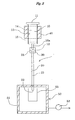
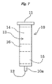
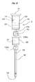
- a column 1 is provided mainly with a first column 10, a second column 20, and a connecting member 30 for connecting the columns 10 and 20 to each other.
- the first column 10 is formed in a cylindrical shape with the lower end 10a having reduced outer and inner diameters, and has openings 11 and 12 at the upper and lower ends, respectively.
- the first column 10 is formed for example of glass or solvent- and heat-resistant plastic, which is packed inside with multilayer silica gel 13.
- the multilayer silica gel 13 consists of an upper layer 14 stacked on a lower layer 15.
- the upper layer 14 is a layer filled with sulfuric acid silica gel, that is, a sulfuric acid silica gel layer, and the sulfuric acid silica gel used herein is prepared by adding concentrated sulfuric acid uniformly to the surface of silica gel.
- the bulk density of sulfuric acid silica gel in the upper layer 14 is not particularly limited, and is usually preferably set at 0.3 to 1.1 g/cm 3 , more preferably 0.5 to 1.0 g/cm 3 .
- the lower layer 15 is a layer filled with silver nitrate silica gel, that is, a silver nitrate silica gel layer, and the silver nitrate silica gel used herein is prepared by adding an aqueous solution of silver nitrate uniformly to the surface of silica gel and then removing water by heating under reduced pressure.
- the bulk density of silver nitrate silica gel in the lower layer 15 is not particularly limited, and is usually preferably set at 0.3 to 0.8 g/cm 3 , more preferably 0.4 to 0.7 g/cm 3 .
- silver nitrate silica gel prepared by using an aqueous solution thereof is different from metal salt hydrate silica gel described later.
- the ratio of the upper layer 14 to the lower layer 15 is established such that the weight ratio of the sulfuric acid silica gel to the silver nitrate silica gel is preferably 1.0 to 50, more preferably 3.0 to 30.
- the weight ratio of the sulfuric acid silica gel is higher than 50, the ratio of the silver nitrate silica gel is reduced, so purification of an electric insulating oil by adsorption action may become insufficient.
- the weight ratio of the sulfuric acid silica gel is lower than 1.0, purification of an electric insulating oil by decomposition action may become insufficient.
- the second column 20 is formed in a cylindrical shape with outer and inner diameters set appropriately identical with those of the lower end 10a of the first column 10, and has openings 21 and 22 at the upper and lower ends, respectively.
- the second column 20 is formed for example of glass or solvent- and heat-resistant plastic, which is packed inside with a layer filled with alumina, that is, an alumina layer 23.
- the alumina used in the alumina layer 23 is not particularly limited as long as it is capable of adsorbing PCBs, and may be any one of basic alumina, neutral alumina and acidic alumina.
- the alumina may be one having various degrees of activity.
- the bulk density of alumina in the alumina layer 23 is not particularly limited, and is usually preferably set at 0.5 to 1.2 g/cm 3 , more preferably 0.8 to 1.1 g/cm 3 .
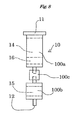
- the connecting member 30, which is a cylindrical member into which the lower end 10a of the first column 10 and the upper end of the second column 20 can be inserted, is formed of a material (for example solvent- and heat-resistant plastic) stable to various solvents, particularly hydrocarbon solvents.
- a material for example solvent- and heat-resistant plastic
- the connecting member 30 With the connecting member 30, the lower end 10a of the first column 10 and the upper end of the second column 20 are detachably connected to each other. It follows that in the column 1 consisting of the first column 10 and the second column 20, the portion of the alumina layer 23 can be separated independently from the upper layer 14 and the lower layer 15.
- the size of the column 1 can be set appropriately depending on the purpose of extraction of PCBs from an oily liquid described later. For example, when the extraction of PCBs from an oily liquid is intended in pretreatment of the oily liquid to measure the concentration of PCBs contained therein, it is only necessary that a small or trace amount of a sample be collected from the oily liquid and subjected to the extraction method of the present invention, and as a consequence, the column 1 can be set small-sized.
- the size of the first column 10 (the size of that portion of the column which can be packed with the upper layer 14 and the lower layer 15) in the column 1 is preferably 10 to 20 mm in inner diameter and 30 to 110 mm in length
- the size of the second column 20 (the size of that portion of the column which can be packed with the alumina layer 23) is preferably 2.0 to 10.0 mm in inner diameter and 10 to 200 mm in length.
- PCBs are extracted from an oily liquid, mainly for the purpose of measuring the concentration of PCBs contained in the oily liquid.
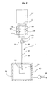
- a first heating unit 40 is arranged around the upper layer 14 of the first column 10, and a suction unit 50 is arranged in the lower end of the second column 20, as shown in FIG. 2 .
- the first heating unit 40 is a heater, a Peltier device or the like and is used to heat the whole of the upper layer 14 to a necessary temperature.
- the suction unit 50 includes a container 51 capable of hermetically accommodating the lower end of the second column 20 and a pump 52 for depressurizing the container 51.
- the container 51 is provided therein with a solvent container 53 for receiving an aliphatic hydrocarbon solvent described later after passage through the column 1.
- a small or trace amount (usually about 1.0 to 500 mg) of a sample is collected from an oily liquid, and this sample is introduced through the opening 11 of the upper end of the first column 10 into the upper layer 14.
- the first heating unit 40 is activated thereby heating the upper layer 14 and keeping it heated for a predetermined time.
- the added sample is retained in the upper layer 14 in the first column 10.
- the heating temperature of the upper layer 14 is set at 35°C or more, preferably 50°C or more, more preferably 60°C or more.
- the upper limit of the heating temperature is not particularly limited, and is usually about 90°C.
- the heating temperature is lower than 35°C, the reaction between the impurities contained in the sample and the sulfuric acid silica gel becomes hardly advanced, thus making it difficult to extract PCBs in a short time from the sample.
- the heating time of the upper layer 14 is set preferably at a period of from 10 minutes to 8 hours. When the heating time is less than 10 minutes, decomposition of the impurities contained in the sample becomes insufficient so that the finally obtained extract may be contaminated with impurity components other than PCBs.
- the oily liquid contains or may contain a large amount of impurity components other than PCBs
- a hydrocarbon solvent capable of dissolving the sample that is, the oily liquid
- the sample is diluted with the hydrocarbon solvent, thereby improving the efficiency of contact of the sample with the sulfuric acid silica gel to increase the reaction efficiency. Accordingly, impurity components (particularly aromatic compounds) other than PCBs contained in the sample are efficiently decomposed in a shorter time in the upper layer 14, and as a consequence, the time required for extraction of PCBs can be reduced.
- the hydrocarbon solvent that can be used herein is usually a C5 to C8 aliphatic saturated hydrocarbon solvent, for example n-pentane, n-hexane, n-heptane, n-octane, isooctane or cyclohexane.
- the hydrocarbon solvent will rapidly volatilize during heating of the first column 10, and thus the reaction efficiency is hardly increased.
- the hydrocarbon solvent may be added continuously after addition of the sample, to the upper layer 14 in the first column 10, or may be previously added to the sample.
- the upper layer 14 heated for a predetermined time in the process described above is then cooled to ordinary temperatures (usually room temperature at about 10 to 30°C) by detaching the first heating unit 40 or by turning off a switch of the first heating unit 40 and leaving the layer as it is.
- ordinary temperatures usually room temperature at about 10 to 30°C
- a first reservoir 60 for supplying a solvent to the first column 10 is then fitted into the opening 11, at the side of the upper end, of the first column 10, and an aliphatic hydrocarbon solvent is stored in the first reservoir 60.
- the pump 52 is actuated, the container 51 is depressurized so that the aliphatic hydrocarbon solvent stored in the first reservoir 60 is supplied continuously and gradually to the first column 10.
- the aliphatic hydrocarbon solvent supplied from the first reservoir 60 to the first column 10 is supplied to the upper layer 14, then passed through the upper layer 14, supplied to the lower layer 15, and passed through the lower layer 15.
- the aliphatic hydrocarbon solvent passed through the lower layer 15 is passed from the opening 12 of the first column 10 via the connecting member 30 and flowed from the opening 21 into the second column 20.
- PCBs retained in the upper layer 14 are dissolved in the aliphatic hydrocarbon solvent and passed, together with the aliphatic hydrocarbon solvent, through the lower layer 15 and flowed into the second column 20.
- a part of decomposition products retained in the upper layer 14 is dissolved in the aliphatic hydrocarbon solvent, transferred to the lower layer 15, adsorbed into the silver nitrate silica gel, and retained in the first column 10.
- the aliphatic hydrocarbon solvent flowed into the second column 20 is supplied to the alumina layer 23 in the second column 20, passed through this layer, discharged from the opening 22 and received by the solvent container 53 in the container 51.
- PCBs dissolved in the aliphatic hydrocarbon solvent from the first column 10 are captured by the alumina layer 23 and retained in the second column 20.
- PCBs are easily captured by the alumina layer 23 and thus retained mainly in the vicinity of the opening 21 in the upper end of the second column 20.
- paraffins that are impurity components other than aromatic compounds contained in the sample are dissolved in the aliphatic hydrocarbon solvent from the first reservoir 60, then passed, together with the aliphatic hydrocarbon solvent, through the alumina layer 23, and received by the solvent container 53.
- the aliphatic hydrocarbon solvent used in this process is capable of dissolving PCBs retained in the first column 10 and is usually a C5 to C8 aliphatic saturated hydrocarbon solvent, for example n-pentane, n-hexane, n-heptane, n-octane, isooctane or cyclohexane. Particularly, n-hexane is preferable.
- the amount of the aliphatic hydrocarbon solvent stored in the first reservoir 60 that is, the total amount of the aliphatic hydrocarbon solvent supplied to the first column 10, is preferably set at 10 to 120 mL.
- the rate of feed of the aliphatic hydrocarbon solvent from the first reservoir 60 is preferably set at 0.2 to 5.0 mL/min. by regulating the depressurized state of the container 51 with the pump 52.
- a second heating unit 70 is arranged around the second column 20.
- the second heating unit 70 used herein is one similar to the first heating unit 40.
- the pump 52 is actuated thereby supplying the second column 20 via the upper-end opening 21 with an inert gas such as nitrogen gas or with air.
- an inert gas such as nitrogen gas or with air.
- the solvent such as the aliphatic hydrocarbon solvent remaining in the second column 20, together with the inert gas, is discharged from the opening 22 at the lower end of the second column 20, thereby removing the solvent such as the aliphatic hydrocarbon solvent from the alumina layer 23.
- the alumina layer 23 in the second column 20 is dry-treated.
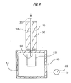
- the second column 20 is detached from the suction unit 50 and then turned upside down by inverting it together with the second heating unit 70.
- the opening 22 of the second column 20 thus turned up by inversion is then provided with a second reservoir 80 for supplying a solvent into the opening 22, and the second reservoir 80 is supplied with a predetermined amount of a hydrophobic solvent.
- the hydrophobic solvent supplied to the second reservoir 80 flows naturally by its own weight from the second reservoir 80 into the second column 20, and is thereby supplied to the alumina layer 23, passed through the alumina layer 23, and discharged from the opening 21 of the second column 20 that was directed downward by inversion.
- the hydrophobic solvent from the second reservoir 80 dissolves PCBs captured by the alumina layer 23, and together with the PCBs, is discharged from the opening 21. Accordingly, when the hydrophobic solvent discharged from the opening 21 is secured, a solution of PCBs in the hydrophobic solvent, that is, the objective extract of PCBs can be obtained.
- PCBs have been captured mainly in the vicinity of the opening 21 side of the alumina layer 23, so that substantially the total amount of PCBs that are captured by the alumina layer 23 comes to be dissolved in the hydrophobic solvent mainly in a first eluate discharged from the second column 20. Accordingly, the objective extract of PCBs can be obtained by merely securing the hydrophobic solvent in a first eluate discharged from the opening 21.
- This extract consists of the first eluate of low volume as described above and is thus in such a small volume as to be easily utilizable in the analytical operation described later,
- the extract of PCBs obtained herein is one obtained by previously removing the aliphatic hydrocarbon solvent from the alumina layer 23 and then supplying the hydrophobic solvent to the second column 20, so that the extract is highly pure with less contamination with the aliphatic hydrocarbon solvent and impurity components dissolved therein.
- the above-described extract can be obtained usually in a short time of about 2 to 10 hours from the step of initiating the operation (the step of adding a sample to the first column 10).
- the second column 20 is supplied with a hydrophobic solvent preferably under heating with the second heating unit 70.
- the heating temperature of the second column 20 is usually set such that the temperature of the alumina layer 23 reaches preferably 35°C or more, more preferably 60°C or more.
- the upper limit of the heating temperature is not particularly limited and is usually about 90°C.
- the hydrophobic solvent used in this extraction step is not particularly limited as long as it is capable of dissolving PCBs.
- the hydrophobic solvent is toluene, a mixed solvent of toluene and an aliphatic hydrocarbon solvent (for example, n-pentane, n-hexane, n-heptane, n-octane, isooctane or cyclohexane), or a mixed solvent of an organochlorine solvent (for example, dichloromethane, trichloromethane or tetrachloromethane) and an aliphatic hydrocarbon solvent (for example, n-pentane, n-hexane, n-heptane, n-octane, isooctane or cyclohexane).
- toluene is preferable because by using it in a smaller amount, PCBs can be extracted from the alumina layer 23.
- the extract obtained in the extraction operation is used as a sample for analysis by gas chromatography.
- Gas chromatography can be carried out with gas chromatographic units equipped with various detectors.
- gas chromatography-mass spectrometry (GC-MS method) or gas chromatography-electron capture detection (GC/ECD method) which is highly sensitive to PCBs, is preferably used.
- GC-MS method gas chromatography-mass spectrometry
- GC/ECD method gas chromatography-electron capture detection
- PCBs contained in a sample for analysis can be quantified in units of isomers and homologs, and thus many findings can be obtained from analysis results.
- the extract obtained by the extraction operation described above may be used after being concentrated as necessary for analysis by gas chromatography.
- the metal salt hydrate silica gel used in the intermediate layer 16 can be prepared by adding an aqueous solution of a metal salt hydrate uniformly to the surface of silica gel and then removing water by heating under reduced pressure
- the metal salt hydrate used herein is a metal salt compound having hydration water and includes, for example, copper sulfate hydrates such as copper sulfate pentahydrate, copper nitrate hydrates such as copper nitrate trihydrate, calcium nitrate hydrates such as calcium nitrate tetrahydrate, and iron(III) nitrate hydrates such as iron(III) nitrate nonahydrate.
- copper salt hydrates such as copper sulfate pentahydrate and copper nitrate trihydrate are preferable.
- the bulk density of the metal salt hydrate silica gel in the intermediate layer 16 is preferably set at 0.3 to 0.8 g/cm 3 , more preferably 0.4 to 0.7 g/cm 3 .
- this bulk density is lower than 0.3 g/cm 3 , the result attained by using the metal salt hydrate silica gel, which will be described later, may be hardly obtained.
- the bulk density is higher than 0.8 g/cm 3 , the rate of chromatographic development of PCBs in the intermediate layer 16 is decreased, and thus a large amount of the aliphatic hydrocarbon solvent may be necessary in the extraction operation described above.
- the amount of the metal salt hydrate silica gel used in the intermediate layer 16 is set at a weight ratio of 0.3 to 4.0, more preferably 0.5 to 2.5, relative to the silver nitrate silica gel forming the lower layer 15.
- the weight ratio of the metal salt hydrate silica gel is lower than 0.3, the result attained by using the metal salt hydrate silica gel, which will be described later, may be hardly obtained.
- the weight ratio is higher than 4.0, the rate of chromatographic development of PCBs in the intermediate layer 16 is decreased, and thus a large amount of the aliphatic hydrocarbon solvent may be necessary in the extraction operation described above.
- the aliphatic hydrocarbon solvent passed through the upper layer 14 consisting of the sulfuric acid silica gel layer 14 is supplied to the intermediate layer 16, passed through the intermediate layer 16, and supplied to the lower layer 15 made of the silver nitrate silica gel. Then, a part of impurity components, particularly electron-donating substances, contained in the aliphatic hydrocarbon solvent from the upper layer 14 are removed by binding to the metal salt hydrate silica gel in the intermediate layer 16.
- Electron-donating substances contained in the aliphatic hydrocarbon solvent from the upper layer 14 are bound to the silver nitrate silica gel, thereby sometimes forming an adsorbent of PCBs having a small number of chlorine atoms (also referred to hereinafter as “low-chlorinated PCBs”), particularly PCBs having 2 chlorine atoms (also referred to hereinafter as “dichlorinated PCBs").
- the lower layer 15 made of the silver nitrate silica gel in which such an adsorbent is formed is supplied successively with the PCB-containing aliphatic hydrocarbon solvent from the upper layer 14, low-chlorinated PCBs contained in the aliphatic hydrocarbon solvent are adsorbed into the lower layer 15 and removed from the aliphatic hydrocarbon solvent, so that the extraction rate (recovery rate) of low-chlorinated PCBs may be lowered.
- the extraction rate (recovery rate) of low-chlorinated PCBs particularly the extraction rate (recovery rate) of dichlorinated PCBs
- the extraction rate (recovery rate) of whole PCBs contained in the oily liquid, particularly in the electric insulating oil can be increased.
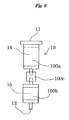
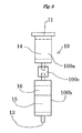
- the first column 10 may be divided for example into an upper column 100a and a lower column 100b arranged vertically which are connected detachably to each other via a connecting member 100c similar to the connecting member 30 described above,
- the upper column 100a forms a multilayer in which an upper layer 14 packed with the sulfuric acid silica gel and an intermediate layer 16 packed with the metal salt hydrate silica gel are stacked
- the lower column 100b forms a lower layer 15 packed with the silver nitrate silica gel.
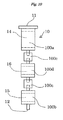
- the first column 10 that can be used in this modified example may be divided, as shown in FIG. 10 , into three vertically arranged columns, that is, an upper column 100a, a middle column 100d and a lower column 100b which are connected detachably between the upper column 100a and the middle column 100d and between the middle column 100d and the lower column 100b via a connecting member 100c similar to the connecting member 30 described above.
- the upper column 100a is packed with the sulfuric acid silica gel to form an upper layer 14
- the middle column 100d is packed with the metal salt hydrate silica gel to form an intermediate layer 16
- the lower column 100b is packed with the silver nitrate silica gel to form a lower layer 15.
- the upper column 100a only is heated with the first heating unit 40.
- a carbon material layer can be arranged in an arbitrary position from the upper layer 14 to the lower end 10a of the first column 10. That is, the carbon material layer can be arranged between the upper layer 14 and the intermediate layer 16 or between the intermediate layer 16 and the lower layer 15, or at the lower end 10a side of the lower layer 15.
- the carbon material layer is arranged preferably in a position near the upper layer 14.
- one preferable example of the column 1 provided with a carbon material layer is one wherein the multilayer silica gel 13 in the first column 10 consisting of a single column is provided with a carbon material layer 17 between an upper layer 14 and an intermediate layer 16.
- Another preferable example of the column 1 provided with a carbon material layer as shown in FIG. 11
- first column 10 is one including a first column 10 consisting of a single column and packed with an upper layer 14, an intermediate layer 16 and a lower layer 15 that are stacked as a multilayer, a second column 20 packed with an alumina layer 23, and a third column 25 packed with a carbon material layer 17, wherein the third column 25 is arranged between the end, at the side of the lower layer 15, of the first column 10 and one end of the second column 20.
- the third column 25 is connected at one end to the end, at the side of the lower layer 15, of the first column 10 via a connecting member 100c similar to the connecting member 30 described above and also connected at the other end to one end of the second column 20 via a similar connecting member 100c.
- a carbon material forming the carbon material layer used in this modified example is active carbon or graphite, preferably in the form of granules to increase the contact area thereof with the aliphatic hydrocarbon solvent passed through the carbon material layer.
- the oily liquid containing PCBs may be contaminated with polychlorinated naphthalenes (PCNs) that resemble PCBs in structure and molecular weight.
- PCNs polychlorinated naphthalenes
- PCNs are dissolved in the aliphatic hydrocarbon solvent, then passed through the upper layer 14 and the lower layer 15 and through the intermediate layer 16 if any and captured by the alumina layer 23 and may, together with PCBs, be extracted with a hydrophobic solvent supplied to, and passed through, the alumina layer 23. Accordingly, PCNs can prevent the extraction of PCBs with high purity from the oily liquid.
- the carbon material layer selectively captures PCNs from the aliphatic hydrocarbon solvent in which PCBs and PCNs are dissolved, thereby separating the PCNs from the aliphatic hydrocarbon solvent. Accordingly, the extraction method in this modified example using the carbon material layer can extract PCBs with high purity even if the oily liquid contains PCNs together with PCBs.
- Typical examples of the oily liquid containing PCNs together with PCBs include the electric insulating oils described above. Before PCBs were added to electric insulating oils for the purpose of increasing electric insulating properties, there was a time when PCNs were added to the oils for the same purpose. At the time when PCBs were used, there was also the circumstance where PCBs were also added to electric insulating oils containing PCNs. Accordingly, there is a high possibility that electric insulating oils that have been long stored for disposal contain PCNs together with PCBs.
- the extraction method in this modified example is particularly effective in extracting PCBs from the electric insulating oils.
- Electric insulating oils A, B, C and D used in the examples and comparative examples below are as follows. Among these oils, the electric insulating oils A, B and C were confirmed to be substantially free of PCNs in analysis by GC/ECD, and the electric insulating oil D was confirmed to contain PCNs in analysis by GC/ECD.
- the concentration of PCNs in the electric insulating oil D is about 24 mg/kg in terms of the concentration of PCBs and is very high as compared with the concentration of coexisting PCBs.
- This oil was prepared by adding equal amounts of 4 kinds of PCB standards (trade names: Kanechlor Kit KC-300, Kanechlor Kit KC-400, Kanechlor Kit KC-500 and Kanechlor Kit KC-600, manufactured by GL Sciences, Inc.) to a commercial electric insulating oil (trade name: JOMO HS Trans N, manufactured by Japan Energy Corporation) such that the total concentration of PCBs reached 0.42 mg/kg.
- PCB standards trade names: Kanechlor Kit KC-300, Kanechlor Kit KC-400, Kanechlor Kit KC-500 and Kanechlor Kit KC-600, manufactured by GL Sciences, Inc.
- a commercial electric insulating oil trade name: JOMO HS Trans N, manufactured by Japan Energy Corporation
- This oil was prepared by adding equal amounts of 4 kinds of PCB standards (trade names: Kanechlor Kit KC-300, Kanechlor Kit KC-400, Kanechlor Kit KC-500 and Kanechlor Kit KC-600, manufactured by GL Sciences, Inc.) to a PCB-free electric insulating oil removed from a used transformer such that the total concentration of PCBs reached 0.42 mg/kg.
- PCB standards trade names: Kanechlor Kit KC-300, Kanechlor Kit KC-400, Kanechlor Kit KC-500 and Kanechlor Kit KC-600, manufactured by GL Sciences, Inc.
- This oil is a PCBs-containing electric insulating oil removed from a used transformer.
- This oil is a PCBs- and PCNs-containing electric insulating oil removed from a used transformer.
- This column was prepared by charging 0.6 g of silver nitrate silica gel to a height of 10 mm in a column of 13 mm in inner diameter and 50 mm in length and then charging 3.5 g of sulfuric acid silica gel to a height of 40 mm thereon.
- This column was prepared by charging 0.5 g of alumina (trade name: MP Alumina B-Super I, manufactured by MP Bio Medicals) in a column of 2.5 mm in inner diameter and 100 mm in length.
- alumina trade name: MP Alumina B-Super I, manufactured by MP Bio Medicals
- the second column was supplied at room temperature (20°C) with toluene in a direction opposite to the direction in which n-hexane was passed, so that PCBs captured by the second column were extracted.
- the rate of toluene supplied was set at 50 ⁇ L/min., and 340 ⁇ L of an initial eluate discharged from the second column was collected as an extract of PCBs. The time taken to obtain this extract after initiation of the operation was about 2.2 hours.
- the collected extract was measured for its concentration of PCBs.
- 50 ⁇ L of an internal standard substance solution for recovery rate calculation was added to the extract, to prepare an analytical sample.
- This analytical sample was analyzed by an HRGC/LRMS method in accordance with the method described in "Temporary Manual for Examination of Exogenous Endocrine-Disrupting Chemicals" presented in October, 1998 by the Environment Agency of Japan, and the concentration of PCBs was calculated by a method described in the same manual.
- the second column was supplied with toluene in a direction opposite to the direction in which n-hexane was passed, so that PCBs captured by the second column were extracted.
- the rate of toluene supplied was set at 50 ⁇ L/min. while the second column was heated at 80°C, and 170 ⁇ L of an initial eluate discharged from the second column was collected as an extract of PCBs. The time taken to obtain this extract after initiation of the operation was about 2 hours.
- the collected extract was measured for its concentration of PCBs.
- the extract was used directly as an analytical sample, and this analytical sample was analyzed by a GC/ECD method in accordance with the method described in Japanese Industrial Standard JIS K 0093 "Testing Methods for Polychlorinated Biphenyl (PCB) in Industrial Water and Waste Water," and the concentration of PCBs was calculated by a method described in the same Japanese Industrial Standard.
- Example 2 An extract was obtained in the same manner as in Example 2 except that the electric insulating oil B was used in place of the electric insulating oil A (provided that similar to Example 1,50 ⁇ Lof an internal standard substance solution for concentration calculation was added to the upper end of the first column). The time taken to obtain this extract after initiation of the operation was about 2 hours. The collected extract was measured for its concentration of PCBs by the same method as in Example 1.
- Example 2 An extract was obtained in the same manner as in Example 2 except that the electric insulating oil B was used in place of the electric insulating oil A. The time taken to obtain this extract after initiation of the operation was about 2 hours. The collected extract was measured for its concentration of PCBs by the same method as in Example 2.
- Example 2 An extract was obtained in the same manner as in Example 2 except that the electric insulating oil C was used in place of the electric insulating oil A (provided that similar to Example 1, 50 ⁇ L of an internal standard substance solution for concentration calculation was added to the upper end of the first column). The time taken to obtain this extract after initiation of the operation was about 2 hours. The collected extract was measured for its concentration of PCBs by the same method as in Example 1.
- Example 2 An extract was obtained in the same manner as in Example 2 except that the electric insulating oil C was used in place of the electric insulating oil A. The time taken to obtain this extract after initiation of the operation was about 2 hours. The collected extract was measured for its concentration of PCBs by the same method as in Example 2.
- the second column was supplied with toluene in a direction opposite to the direction in which n-hexane was passed, so that PCBs captured by the second column were extracted.
- the rate of toluene supplied was set at 50 ⁇ L/min. while the second column was heated at 80°C, and 170 ⁇ L of an initial eluate discharged from the second column was collected as an extract of PCBs. The time taken to obtain this extract after initiation of the operation was about 7.5 hours.
- the collected extract was measured for its concentration of PCBs.
- 50 ⁇ L of an internal standard substance solution for recovery rate calculation was added to the extract, to prepare an analytical sample, and this analytical sample was analyzed by an HRGC/LRMS method in accordance with the method described in "Temporary Manual for Examination of Exogenous Endocrine-Disrupting Chemicals" presented in October, 1998 by the Environment Agency of Japan, and the concentration of PCBs was calculated by a method described in the same manual.
- PCBs obtained from the electric insulating oil A in the same manner as in Example 7 were measured for its concentration of PCBs.
- the extract was used directly as an analytical sample, and this analytical sample was analyzed by a GC/ECD method in accordance with the method described in Japanese Industrial Standard JIS K 0093 "Testing Methods for Polychlorinated Biphenyl (PCB) in Industrial Water and Waste Water," and the concentration of PCBs was calculated by a method described in the same Japanese Industrial Standard.
- An extract of PCBs was obtained from the electric insulating oil A in the same manner as in Example 7 except that the heating treatment conditions of the sulfuric acid silica gel layer in the first column were changed to 80°C and 30 minutes, the heating temperature of the second column was changed to 40°C, and toluene supplied to the second column was changed to dichloromethane-containing n-hexane (dichloromethane concentration: 20% by volume). The time taken to obtain this extract after initiation of the operation was about 2 hours. Then, this extract was measured for its concentration of PCBs by the same method as in Example 7.
- An analytical sample for concentration of PCBs was prepared from the electric insulating oil A, and the concentration of PCBs in the electric insulating oil A was measured.
- preparation of the analytical sample and measurement of the concentration of PCBs followed the method described in Appendix No. 2 in Announcement No. 192 issued in 1992 by the Ministry of Health and Welfare of Japan "Method of Testing Standards Concerned with General Waste Subject to Special Control and Industrial Waste Subject to Special Control" (that is, the previously described official method).
- the time taken to prepare the analytical sample was about 3 days.
- the concentration of PCBs in the electric insulating oil A was measured. Specifically, 85 mg of the electric insulating oil A was added to the upper end of a multilayer silica gel column specified by the same measurement method, and n-hexane was supplied at a rate of 2.5 mL/min. to the upper end of this multilayer silica gel column. Then, the whole volume of the n-hexane solution passed through the multilayer silica gel column was collected and concentrated in a rotary evaporator.
- the whole volume of the concentrated n-hexane solution was added to the upper end of an alumina column specified by the same measurement method, and 10 mL of n-hexane was supplied at a rate of 2.5 mL/min, to the upper end of the alumina column.
- 10 mL of n-hexane was supplied at a rate of 2.5 mL/min, to the upper end of the alumina column.
- 60 mL of dichloromethane-containing n-hexane (dichloromethane concentration: 5% by volume) was supplied at a rate of 2.5 mL/min. to the upper end of the alumina column, and the whole volume of the dichloromethane-containing n-hexane solution passed through the alumina column was collected.
- This dichloromethane-containing n-hexane solution was concentrated in a rotary evaporator, then transferred to a small-quantity concentrating tube, and gently further concentrated while the small-quantity concentrating tube was supplied with a nitrogen stream. The time taken to obtain this concentrate after initiation of the operation was 6 hours.
- the concentrate thus obtained was measured for its concentration of PCBs.
- 50 ⁇ L of an internal standard substance solution for recovery rate calculation was added to the concentrate, to prepare an analytical sample.
- This analytical sample was analyzed by the HRGC/HRMS method in accordance with the same method as in Comparative Example 1, and calculation of the concentration of PCBs was attempted by the method described in the same manual.
- Example 1-1 and Table 1-2 The extraction conditions and the like in Examples 1 to 14 and Comparative Examples 1 to 6 are collectively shown in Table 1-1 and Table 1-2.
- the measurement results of concentrations of PCBs in Examples 1 to 14 and Comparative Examples 1 to 6 are shown in Table 2-1 and Table 2-2, and the ment results of recovery rates of PCBs in some of Examples 1 to 14 and Comparative Examples 1 to 6 are shown in Table 3.
- the recovery rates of PCBs shown in Table 3 are based on the internal standard substance for concentration calculation and the internal standard substance for recovery rate calculation.
- the concentrations of PCBs in the electric insulating oil A measured in Examples 1, 2 and 7 to 14 agree approximately with the result of Comparative Example 1 where the concentration of PCBs in the electric insulating oil A was measured by the official method.
- the concentrations of PCBs in the electric insulating oil B measured in Examples 3 and 4 agree approximately with the result of Comparative Example 2 where the concentration of PCBs in the electric insulating oil B was measured by the official method.
- the concentrations of PCBs in the electric insulating oil C measured in Examples 5 and 6 agree approximately with the result of Comparative Example 3 where the concentration of PCBs in the electric insulating oil C was measured by the official method.
- the method for extracting PCBs from the respective electric insulating oils in Examples 1 to 14 although the operation is easy and the time taken for treatment is significantly short as compared with the official method, can pretreat the electric insulating oils with the same accuracy as in the official method.
- Table 2-2 shows that the concentration of PCBs could not be measured in Comparative Example 4. This is because in Comparative Example 4, variations such as waving (rock mass variations) in a chromatogram in monitor channel of the standard for mass calibration are observed in analysis by the HRGC/HRMS method, as shown in FIG. 13 , and thus a significant reduction in analytical precision was suspected.
- the reason that rock mass variations were observed in Comparative Example 4 is that impurity components were not sufficiently removed at the time of extraction of PCBs from the electric insulating oil A.
- Standards such as JIS K 0311 stipulate that because the pretreatment of a sample is considered insufficient when rock mass variations are observed, the pretreatment of the sample be sufficiently performed again.
- Table 2-2 indicates that the concentration of PCBs could not be measured in Comparative Examples 5 and 6. This is because similarly to Comparative Example 4, impurity components were not sufficiently removed at the time of extraction of PCBs from the electric insulating oil A, and thus a significant reduction in analytical precision was suspected in analysis by the HRGC/LRMS method or GC/ECD method.
- This column was prepared by charging 0.3 g of silver nitrate silica gel to a height of 5 mm in a column of 13 mm in inner diameter and 55 mm in length, then charging 0.6 g of copper nitrate silica gel to a height of 10 mm thereon and further charging 3.5 g of sulfuric acid silica gel to a height of 40 mm thereon.
- the copper nitrate silica gel used herein was prepared in the following manner. 1.0 g of water was added to 3.5 g of copper nitrate trihydrate, thereby sufficiently dissolving it to prepare an aqueous solution. This aqueous solution was added uniformly via a pipette to the surface of 10 g of silica gel and then heated at 70°C for 2 hours under reduced pressure in a rotary evaporator to remove water. The copper nitrate silica gel thus obtained contains 20% by weight of copper nitrate.
- This column was prepared in the same manner as for the first column A except that copper sulfate silica gel was used in place of copper nitrate silica gel.
- the copper sulfate silica gel used herein was prepared in the following manner. 10 g of water was added to 4.0 g of copper sulfate pentahydrate, thereby sufficiently dissolving it to prepare an aqueous solution. This aqueous solution was added uniformly via a pipette to the surface of 10 g of silica gel and then heated at 70°C for 2 hours under reduced pressure in a rotary evaporator to remove water. The copper sulfate silica gel thus obtained contains 20% by weight of copper sulfate.
- This column was prepared in the same manner as for the first column A except that calcium nitrate silica gel was used in place of copper nitrate silica gel.
- the calcium nitrate silica gel used herein was prepared in the following manner. 2.0 g of water was added to 4.0 g of calcium nitrate tetrahydrate, thereby sufficiently dissolving it to prepare an aqueous solution. This aqueous solution was added uniformly via a pipette to the surface of 10 g of silica gel and then heated at 70°C for 2 hours under reduced pressure in a rotary evaporator to remove water. The calcium nitrate silica gel thus obtained contains 20% by weight of calcium nitrate.
- This column was prepared in the same manner as for the first column A except that iron(III) nitrate silica gel was used in place of copper nitrate silica gel.
- the iron(III) nitrate silica gel used herein was prepared in the following manner. 2.0 g of water was added to 6.0 g of iron(III) nitrate nonahydrate, thereby sufficiently dissolving it to prepare an aqueous solution. This aqueous solution was added uniformly via a pipette to the surface of 10 g of silica gel and then heated at 70°C for 2 hours under reduced pressure in a rotary evaporator to remove water.
- the iron(III) nitrate silica gel thus obtained contains 26% by weight of iron(III) nitrate.
- the second column was supplied at room temperature (20°C) with toluene in a direction opposite to the direction in which n-hexane was passed, so that PCBs captured by the second column were extracted.
- the rate of toluene supplied was set at 50 ⁇ L/min., and 340 ⁇ L of an initial eluate discharged from the second column was collected as an extract of PCBs. The time taken to obtain this extract after initiation of the operation was about 2.2 hours.
- the collected extract was measured for its concentration of PCBs.
- 50 ⁇ L of an internal standard substance solution for recovery rate calculation was added to the extract, to prepare an analytical sample.
- This analytical sample was analyzed by an HRGC/LRMS method in accordance with the method described in "Temporary Manual for Examination of Exogenous Endocrine-Disrupting Chemicals" presented in October, 1998 by the Environment Agency of Japan, and the concentration of PCBs was calculated by a method described in the same manual.
- the second column was supplied with toluene in a direction opposite to the direction in which n-hexane was passed, so that PCBs captured by the second column were extracted.
- the rate of toluene supplied was set at 50 ⁇ L/min. while the second column was heated at 80°C, and 170 ⁇ L of an initial eluate discharged from the second column was collected as an extract of PCBs. The time taken to obtain this extract after initiation of the operation was about 2 hours.
- the collected extract was measured for its concentration of PCBs.
- the extract was used directly as an analytical sample, and this analytical sample was analyzed by a GC/ECD method in accordance with the method described in Japanese Industrial Standard JIS K 0093 "Testing Methods for Polychlorinated Biphenyl (PCB) in Industrial Water and Waste Water," and the concentration of PCBs was calculated by a method described in the same Japanese Industrial Standard.
- the second column was supplied with toluene in a direction opposite to the direction in which n-hexane was passed, so that PCBs captured by the second column were extracted.
- the rate of toluene supplied was set at 50 ⁇ L/min. while the second column was heated at 80°C, and 170 ⁇ L of an initial eluate discharged from the second column was collected as an extract of PCBs. The time taken to obtain this extract after initiation of the operation was about 7.5 hours.
- the collected extract was measured for its concentration of PCBs.
- 50 ⁇ L of an internal standard substance solution for recovery rate calculation was added to the extract, to prepare an analytical sample.
- This analytical sample was analyzed by an HRGC/LRMS method in accordance with the method described in "Temporary Manual for Examination of Exogenous Endocrine-Disrupting Chemicals" presented in October, 1998 by the Environment Agency of Japan, and the concentration of PCBs was calculated by a method described in the same manual.
- An extract of PCBs was obtained from the electric insulating oil C in the same manner as in Example 17 (provided that 50 ⁇ L of an internal standard substance solution for concentration calculation was not added to the upper end of the first column A) except that isooctane was not added to the first column A, the heating treatment conditions of the sulfuric acid silica gel layer in the first column A were changed to 60°C and 1 hour, toluene was added to the second column at room temperature without heating the second column, and 340 ⁇ L of an initial eluate discharged from the second column was collected as an extract of PCBs. The time taken to obtain this extract after initiation of the operation was about 2.7 hours. Then, this extract was measured for its concentration of PCBs by the same method as in Example 18.
- An extract of PCBs was obtained from the electric insulating oil C in the same manner as in Example 17 except that the heating treatment conditions of the sulfuric acid silica gel layer in the first column A were changed to 80°C and 30 minutes, the heating temperature of the second column was changed to 40°C, and toluene supplied to the second column was changed to dichloromethane-containing n-hexane (dichloromethane concentration: 20% by volume). The time taken to obtain this extract after initiation of the operation was about 2 hours. Then, this extract was measured for its concentration of PCBs by the same method as in Example 17.
- the concentration of PCBs in the electric insulating oil C was measured according to Japanese Industrial Standard JIS K 0311 "Method for Determination of Dioxins in Stationary Source Emissions". Specifically, 85 mg of the electric insulating oil C was added to the upper end of a multilayer silica gel column specified by the same measurement method, and n-hexane was supplied at a rate of 2.5 mL/min. to the upper end of this multilayer silica gel column. Then, the whole volume of the n-hexane solution passed through the multilayer silica gel column was collected and concentrated in a rotary evaporator.
- the whole volume of the concentrated n-hexane solution was added to the upper end of an alumina column specified by the same measurement method, and 10 mL of n-hexane was supplied at a rate of 2.5 mL/min. to the upper end of the alumina column.
- 10 mL of n-hexane was supplied at a rate of 2.5 mL/min. to the upper end of the alumina column.
- 60 mL of dichloromethane-containing n-hexane (dichloromethane concentration: 5% by volume) was supplied at a rate of 2.5 mL/min. to the upper end of the alumina column, and the whole volume of the dichloromethane-containing n-hexane solution passed through the alumina column was collected.
- This dichloromethane-containing n-hexane solution was concentrated in a rotary evaporator, then transferred to a small-quantity concentrating tube, and gently further concentrated while the small-quantity concentrating tube was supplied with a nitrogen stream. The time taken to obtain this concentrate after initiation of the operation was 6 hours.
- the concentrate thus obtained was measured for its concentration of PCBs.
- 50 ⁇ L of an internal standard substance solution for recovery rate calculation was added to the concentrate, to prepare an analytical sample.
- This analytical sample was analyzed by the HRGC/HRMS method in accordance with the same method as in Comparative Example 1, and calculation of the concentration of PCBs was attempted by the method described in the same manual.
- Example 15 to 30 and Comparative Examples 7 to 9 are collectively shown in Table 4-1 and Table 4-2.
- the measurement results of concentrations of PCBs in Examples 15 to 30 and Comparative Examples 7 to 9 are shown in Table 5-1 and Table 5-2, and the measurement results of recovery rates of PCBs in some of Examples 15 to 30 and Comparative Examples 7 to 9 are shown in Table 6.
- the recovery rates of PCBs shown in Table 6 are based on the internal standard substance for concentration calculation and the internal standard substance for recovery rate calculation.
- the result of Comparative Example 3 as a comparative example for Examples 15 to 30 is also shown in Table 5-1, Table 5-2 and Table 6.
- the concentrations of PCBs in the electric insulating oil C measured in Examples 15 to 30 agree approximately with the result of Comparative Example 3 where the concentration of PCBs in the electric insulating oil C was measured by the official method. Accordingly, the method for extracting PCBs from the electric insulating oil C in Examples 15 to 30, although the operation is easy and the time taken for treatment is significantly short as compared with the official method, can pretreat the electric insulating oil C with the same accuracy as in the official method.
- Table 5-2 shows that the concentration of PCBs could not be measured in Comparative Example 7. This is because in Comparative Example 7, impurity components were not sufficiently removed at the time of extraction of PCBs from the electric insulating oil C, and thus rock mass variations similar to those in Comparative Example 4 were observed in analysis by the HRGC/HRMS method, and therefore, a significant reduction in analytical precision was suspected.
- Table 5-2 shows that the concentration of PCBs could not be measured in Comparative Examples 8 and 9. This is because similarly to Comparative Example 7, impurity components were not sufficiently removed at the time of extraction of PCBs from the electric insulating oil C, and therefore, a significant reduction in analytical precision was suspected in analysis by the HRGC/LRMS method or GC/ECD method.
- the first columns A, A1, A2 and A3, the first column B1, the first column Cl, the first column D1 and the second column used in the following Examples 31 to 42 and Comparative Examples 10 to 13 are as follows.
- the granular graphite used in the first column is "Envi-Carb 120/400" manufactured by Supelco US.
- This column is the same as the first column A used in Example II.
- This column was prepared by charging the first column A used in Example II with 0.1 g of granular graphite to a height of 2 mm between sulfuric acid silica gel and copper nitrate silica gel.
- This column was prepared by charging the first column A used in Example II with 0.1 g of granular graphite to a height of 2 mm between copper nitrate silica gel and silver nitrate silica gel.
- This column was prepared by charging the first column A used in Example II with 0.1 g of granular graphite to a height of 2 mm below silver nitrate silica gel.
- This column was prepared by charging the first column B used in Example II with 0.1 g of granular graphite to a height of 2 mm between sulfuric acid silica gel and copper sulfate silica gel.
- This column was prepared by charging the first column C used in Example II with 0.1 g of granular graphite to a height of 2 mm between sulfuric acid silica gel and calcium nitrate silica gel.
- This column was prepared by charging the first column D used in Example II with 0.1 g of granular graphite to a height of 2 mm between sulfuric acid silica gel and iron(III) nitrate silica gel.
- the second column was supplied with toluene at 80°C in a direction opposite to the direction in which n-hexane was passed, so that PCBs captured by the second column were extracted.
- the rate of toluene supplied was set at 50 ⁇ L/min., and 170 ⁇ L of an initial eluate discharged from the second column was collected as an extract of PCBs. The time taken to obtain this extract after initiation of the operation was about 2 hours.
- the collected extract was measured for its concentration of PCBs.
- 50 ⁇ L of an internal standard substance solution for recovery rate calculation was added to the extract, to prepare an analytical sample.
- This analytical sample was analyzed by an HRGC/LRMS method in accordance with the method described in "Temporary Manual for Examination of Exogenous Endocrine-Disrupting Chemicals" presented in October, 1998 by the Environment Agency of Japan, and the concentration of PCBs was calculated by a method described in the same manual.
- the second column was supplied with toluene in a direction opposite to the direction in which n-hexane was passed, so that PCBs captured by the second column were extracted.
- the rate of toluene supplied was set at 50 ⁇ L/min. while the second column heated at 80°C, and 170 ⁇ L of an initial eluate discharged from the second column was collected as an extract of PCBs. The time taken to obtain this extract after initiation of the operation was about 2 hours.
- the collected extract was measured for its concentration of PCBs.
- the extract was used directly as an analytical sample, and this analytical sample was analyzed by a GC/ECD method in accordance with the method described in Japanese Industrial Standard JIS K 0093 "Testing Methods for Polychlorinated Biphenyl (PCB) in Industrial Water and Waste Water", and the concentration of PCBs was calculated by a method described in the same Japanese Industrial Standard.
- 0.1 g of granular graphite was packed to a height of 55 mm in a glass tube of 2.5 mm in diameter and 60 mm in length sealed at one end with glass wool, and then this glass tube was sealed at the other end with glass wool.
- One end of this glass tube was connected via a connecting tube to the lower end of the first column A allowed to stand such that the sulfuric acid silica gel layer became an upper layer.
- 85 mg of the electric insulating oil D and 0.40 mL of isooctane were added to the upper end of the first column A.
- the sulfuric acid silica gel layer in this first column A was heated at 80°C for 30 minutes and cooled to room temperature, and then the second column was connected via a connecting tube to the lower end of the glass tube.
- n-hexane 20 mL of n-hexane was supplied at a rate of 1 mL/min. to the upper end of the first column A and then discharged from the lower end of the second column.
- the second column was detached from the glass tube, and n-hexane remaining in the second column was removed.
- the second column was supplied with a nitrogen gas, while the second column was heated at 80°C.
- the second column was supplied with toluene in a direction opposite to the direction in which n-hexane was passed, so that PCBs captured by the second column were extracted.
- the rate of toluene supplied was set at 50 ⁇ L/min. while the second column was heated at 80°C, and 170 ⁇ L of an initial eluate discharged from the second column was collected as an extract of PCBs. The time taken to obtain this extract after initiation of the operation was about 2 hours.
- the collected extract was measured for its concentration of PCBs.
- the extract was used directly as an analytical sample, and this analytical sample was analyzed by a GC/ECD method in accordance with the method described in Japanese Industrial Standard JIS K 0093 "Testing Methods for Polychlorinated Biphenyl (PCB) in Industrial Water and Waste Water", and the concentration of PCBs was calculated by a method described in the same Japanese Industrial Standard.
- An extract of PCBs was obtained from the electric insulating oil D in the same manner as in Example 32 except that the solvent added to the first column A1 was changed from isooctane to n-hexane and the heating conditions of the sulfuric acid silica gel layer were changed from 80°C and 30 minutes to 40°C and 6 hours. The time taken to obtain this extract after initiation of the operation was about 7.5 hours. Then, this extract was measured for its concentration of PCBs by the same method as in Example 32.
- the concentration of PCBs in the electric insulating oil D was measured according to Japanese Industrial Standard JIS K 0311 "Method for Determination of Dioxins in Stationary Source Emissions". Specifically, 85 mg of the electric insulating oil D was added to the upper end of a multilayer silica gel column specified by the same measurement method, and n-hexane was supplied at a rate of 2.5 mL/min. to the upper end of this multilayer silica gel column. Then, the whole volume of the n-hexane solution passed through the multilayer silica gel column was collected and concentrated in a rotary evaporator.
- the whole volume of the concentrated n-hexane solution was added to the upper end of an alumina column specified by the same measurement method, and 10 mL of n-hexane was supplied at a rate of 2.5 mL/min. to the upper end of the alumina column.
- 10 mL of n-hexane was supplied at a rate of 2.5 mL/min. to the upper end of the alumina column.
- 60 mL of dichloromethane-containing n-hexane (dichloromethane concentration: 5% by volume) was supplied at a rate of 2.5 mL/min. to the upper end of the alumina column, and the whole volume of the dichloromethane-containing n-hexane solution passed through the alumina column was collected.
- This dichloromethane-containing n-hexane solution was concentrated in a rotary evaporator, then transferred to a small-quantity concentrating tube, and gently further concentrated while the small-quantity concentrating tube was supplied with a nitrogen stream. The time taken to obtain this concentrate after initiation of the operation was 6 hours.
- the concentrate thus obtained was measured for its concentration of PCBs.
- 50 ⁇ L of an internal standard substance solution for recovery rate calculation was added to the concentrate, to prepare an analytical sample.
- This analytical sample was analyzed by the HRGC/HRMS method in accordance with the same method as in Comparative Example 3, and calculation of the concentration of PCBs was attempted by the method described in the same manual.
- Example 31 to 42 and Comparative Examples 10 to 13 are collectively shown in Table 7.
- the measurement results of concentrations of PCBs in Examples 31 to 42 and Comparative Examples 10 to 13 are shown in Table 8-1 and Table 8-2, and the measurement results of recovery rates of PCBs in some of Examples 31 to 42 and Comparative Examples 10 to 13 are shown in Table 9.
- the recovery rates of PCBs shown in Table 9 are based on the internal standard substance for concentration calculation and the internal standard substance for recovery rate calculation.
- the result of Comparative Example 3 as a comparative example for Examples 41 and 42 is also shown in Tables 8-2 and 9.
- the concentrations of PCBs in the electric insulating oil D measured in Examples 31 to 40 agree approximately with the result of Comparative Example 10 where the concentration ofPCBs in the electric insulating oil D was measured by the official method. Accordingly, the method for extracting PCBs from the electric insulating oil D in Examples 31 to 40, although the electric insulating oil D contains PCNs, can pretreat the electric insulating oil D effectively in a short time.
- Table 8-2 shows that the concentration of PCBs could not be measured in Comparative Example 11. This is because in Comparative Example 11, impurity components were not sufficiently removed at the time of extraction of PCBs from the electric insulating oil D, and thus rock mass variations similar to those in Comparative Example 4 were observed in analysis by the HRGC/HRMS method, and therefore, a significant reduction in analytical precision was suspected.
- Table 8-2 shows that the concentration of PCBs could not be measured in Comparative Examples 12 and 13. This is because similarly to Comparative Example 7, impurity components were not sufficiently removed at the time of extraction of PCBs from the electric insulating oil D, and therefore, a significant reduction in analytical precision was suspected in analysis by the HRGC/LRMS method or GC/ECD method.
Landscapes
- Chemical & Material Sciences (AREA)
- Analytical Chemistry (AREA)
- Health & Medical Sciences (AREA)
- Life Sciences & Earth Sciences (AREA)
- Chemical Kinetics & Catalysis (AREA)
- Physics & Mathematics (AREA)
- Pathology (AREA)
- Biochemistry (AREA)
- General Health & Medical Sciences (AREA)
- General Physics & Mathematics (AREA)
- Immunology (AREA)
- Inorganic Chemistry (AREA)
- Organic Chemistry (AREA)
- Engineering & Computer Science (AREA)
- Food Science & Technology (AREA)
- General Chemical & Material Sciences (AREA)
- Oil, Petroleum & Natural Gas (AREA)
- Medicinal Chemistry (AREA)
- Spectroscopy & Molecular Physics (AREA)
- Electrochemistry (AREA)
- Molecular Biology (AREA)
- Sampling And Sample Adjustment (AREA)
- Other Investigation Or Analysis Of Materials By Electrical Means (AREA)
- Solid-Sorbent Or Filter-Aiding Compositions (AREA)
- Treatment Of Liquids With Adsorbents In General (AREA)
Applications Claiming Priority (3)
| Application Number | Priority Date | Filing Date | Title |
|---|---|---|---|
| JP2007089876 | 2007-03-29 | ||
| JP2007240424 | 2007-09-18 | ||
| PCT/JP2008/056004 WO2008123393A1 (ja) | 2007-03-29 | 2008-03-21 | ポリ塩化ビフェニル類の抽出方法 |
Publications (3)
| Publication Number | Publication Date |
|---|---|
| EP2136196A1 true EP2136196A1 (de) | 2009-12-23 |
| EP2136196A4 EP2136196A4 (de) | 2012-09-05 |
| EP2136196B1 EP2136196B1 (de) | 2018-06-27 |
Family
ID=39830878
Family Applications (1)
| Application Number | Title | Priority Date | Filing Date |
|---|---|---|---|
| EP08739128.0A Active EP2136196B1 (de) | 2007-03-29 | 2008-03-21 | Verfahren zur extraktion von polychlorinierten biphenylen |
Country Status (7)
| Country | Link |
|---|---|
| US (1) | US8329473B2 (de) |
| EP (1) | EP2136196B1 (de) |
| JP (1) | JP4465430B2 (de) |
| KR (1) | KR101163431B1 (de) |
| CN (1) | CN101652651B (de) |
| TW (1) | TWI399235B (de) |
| WO (1) | WO2008123393A1 (de) |
Cited By (2)
| Publication number | Priority date | Publication date | Assignee | Title |
|---|---|---|---|---|
| US20110198291A1 (en) * | 2008-12-25 | 2011-08-18 | Katsuhisa Honda | Purifying agent for oily liquid containing polychlorinated biphenyls |
| CN111939597A (zh) * | 2020-08-07 | 2020-11-17 | 青岛理工大学 | 一种串联式层析柱装置及方法 |
Families Citing this family (17)
| Publication number | Priority date | Publication date | Assignee | Title |
|---|---|---|---|---|
| JP5523915B2 (ja) * | 2009-11-30 | 2014-06-18 | 秀基 戸井田 | 被分析液抽出装置 |
| KR101021690B1 (ko) * | 2010-05-12 | 2011-03-22 | (주)원창에너지 | 폴리염화비페닐을 함유하는 폐절연유의 처리 방법 |
| CN102359994B (zh) * | 2011-07-21 | 2014-01-08 | 广东出入境检验检疫局检验检疫技术中心 | 电子电气产品橡胶部件中多氯萘含量的检测方法 |
| JP5626538B2 (ja) * | 2012-01-23 | 2014-11-19 | 三浦工業株式会社 | ポリ塩化ビフェニル類の抽出方法 |
| CN103364238B (zh) * | 2012-04-10 | 2015-09-09 | 中国科学院大连化学物理研究所 | 复杂样品中PCNs、HBCDs和TBBPA的选择性分离 |
| JP6086597B2 (ja) * | 2013-07-19 | 2017-03-01 | 三浦工業株式会社 | ポリ塩化ビフェニル類の抽出方法 |
| CN103884812A (zh) * | 2014-03-26 | 2014-06-25 | 昆山洛丹伦生物科技有限公司 | 一种电子元器件塑料部件中多氯化萘的检测方法 |
| CN104084180B (zh) * | 2014-06-30 | 2015-06-17 | 中华人民共和国湖北出入境检验检疫局 | 检测多溴联苯类化合物的多层硅胶净化色谱柱的制备方法 |
| CN106501431B (zh) * | 2016-10-19 | 2017-11-10 | 中国检验认证集团湖北有限公司 | 一种采用硅胶色谱柱检测乳制品中多氯联苯的方法 |
| CN107064395B (zh) * | 2017-06-09 | 2018-12-25 | 中国环境科学研究院 | 复合硅胶柱和用于分析样品中有机污染物的前处理方法 |
| JP7015705B2 (ja) * | 2018-02-09 | 2022-02-03 | 三浦工業株式会社 | ポリ塩化ビフェニル類の抽出方法 |
| JP2021032666A (ja) | 2019-08-22 | 2021-03-01 | 三浦工業株式会社 | 油類の精製方法 |
| CN114264758B (zh) * | 2020-09-16 | 2023-04-07 | 南京理工大学 | 检测沉积物中PCBs、PBDEs和EHFRs的前处理方法 |
| JP2022055260A (ja) * | 2020-09-28 | 2022-04-07 | 三浦工業株式会社 | 有機ハロゲン化合物の抽出方法 |
| CN113311083B (zh) * | 2021-05-24 | 2022-12-16 | 广东产品质量监督检验研究院(国家质量技术监督局广州电气安全检验所、广东省试验认证研究院、华安实验室) | 一种鱼鳞中七种指示性多氯联苯的测定方法 |
| CN113800657B (zh) * | 2021-10-12 | 2022-11-04 | 中国石油化工股份有限公司 | 一种地下水DNAPLs原位处理方法及处理装置 |
| CN113990407B (zh) * | 2021-10-27 | 2022-08-05 | 北京中科三清环境技术有限公司 | 对多氯萘及其同系物的含量及来源进行解析的解析方法 |
Family Cites Families (14)
| Publication number | Priority date | Publication date | Assignee | Title |
|---|---|---|---|---|
| JPS6168119A (ja) * | 1984-09-11 | 1986-04-08 | Shinryo Air Conditioning Co Ltd | 吸湿剤およびそれを用いた除湿方法 |
| JP2000028598A (ja) * | 1998-07-14 | 2000-01-28 | Ebara Corp | 全自動試料連続精製・分析装置及び精製・分析方法 |
| JP3578315B2 (ja) * | 1998-09-17 | 2004-10-20 | 株式会社荏原製作所 | 絶縁油中のポリ塩化ビフェニル類(pcb)分析法 |
| JP2001330598A (ja) | 2000-05-22 | 2001-11-30 | Fuji Chemical Industries Ltd | 多層充填剤充填カラム |
| US7588725B2 (en) * | 2001-04-25 | 2009-09-15 | Biotrove, Inc. | High throughput autosampler |
| JP4671541B2 (ja) * | 2001-06-11 | 2011-04-20 | 日本曹達株式会社 | 難分解性ハロゲン化合物の含有量の測定方法。 |
| JP4323760B2 (ja) | 2001-07-30 | 2009-09-02 | 財団法人電力中央研究所 | Pcb分離方法 |
| JP4744044B2 (ja) * | 2001-09-27 | 2011-08-10 | 関東化学株式会社 | 脱水剤を分散した繊維マトリックス、その製造方法およびそれを用いたクリーンアップ用カラム |
| CN100436317C (zh) | 2003-05-15 | 2008-11-26 | 卡奴母鲁·拉乌·拉居 | 利用功能性过渡金属硅酸盐控制微生物的方法 |
| JP2005140522A (ja) * | 2003-11-04 | 2005-06-02 | Sumika Chemical Analysis Service Ltd | ポリ塩化ビフェニル類を含む油性試料の前処理方法 |
| JP2006047044A (ja) * | 2004-08-03 | 2006-02-16 | Shimadzu Corp | 絶縁油中pcbの分析法 |
| US7344686B2 (en) * | 2004-10-07 | 2008-03-18 | Mesoscopic Devices, Inc. | Desulfurization apparatus with individually controllable heaters |
| US20090107213A1 (en) * | 2005-06-07 | 2009-04-30 | Katsuhisa Honda | Method for preparing sample for analysis of dioxins |
| JP4003083B2 (ja) * | 2005-08-03 | 2007-11-07 | 株式会社エコアップ | 絶縁油の精製方法 |
-
2008
- 2008-03-21 CN CN200880010976XA patent/CN101652651B/zh active Active
- 2008-03-21 US US12/593,483 patent/US8329473B2/en not_active Expired - Fee Related
- 2008-03-21 EP EP08739128.0A patent/EP2136196B1/de active Active
- 2008-03-21 JP JP2008551380A patent/JP4465430B2/ja active Active
- 2008-03-21 WO PCT/JP2008/056004 patent/WO2008123393A1/ja not_active Ceased
- 2008-03-21 KR KR1020097019144A patent/KR101163431B1/ko not_active Expired - Fee Related
- 2008-03-25 TW TW097110484A patent/TWI399235B/zh active
Cited By (4)
| Publication number | Priority date | Publication date | Assignee | Title |
|---|---|---|---|---|
| US20110198291A1 (en) * | 2008-12-25 | 2011-08-18 | Katsuhisa Honda | Purifying agent for oily liquid containing polychlorinated biphenyls |
| EP2345883A4 (de) * | 2008-12-25 | 2012-09-05 | Univ Ehime | Reinigungsmittel für ölige flüssigkeiten mit polybiphenylchlorid |
| US9157899B2 (en) | 2008-12-25 | 2015-10-13 | Ehime University | Purifying agent for oily liquid containing polychlorinated biphenyls |
| CN111939597A (zh) * | 2020-08-07 | 2020-11-17 | 青岛理工大学 | 一种串联式层析柱装置及方法 |
Also Published As
| Publication number | Publication date |
|---|---|
| TW200902485A (en) | 2009-01-16 |
| KR20100014393A (ko) | 2010-02-10 |
| JPWO2008123393A1 (ja) | 2010-07-15 |
| US8329473B2 (en) | 2012-12-11 |
| CN101652651A (zh) | 2010-02-17 |
| TWI399235B (zh) | 2013-06-21 |
| JP4465430B2 (ja) | 2010-05-19 |
| EP2136196B1 (de) | 2018-06-27 |
| EP2136196A4 (de) | 2012-09-05 |
| WO2008123393A1 (ja) | 2008-10-16 |
| CN101652651B (zh) | 2012-03-21 |
| KR101163431B1 (ko) | 2012-07-13 |
| US20100116023A1 (en) | 2010-05-13 |
Similar Documents
| Publication | Publication Date | Title |
|---|---|---|
| EP2136196B1 (de) | Verfahren zur extraktion von polychlorinierten biphenylen | |
| US9157899B2 (en) | Purifying agent for oily liquid containing polychlorinated biphenyls | |
| Comerton et al. | Practical overview of analytical methods for endocrine-disrupting compounds, pharmaceuticals and personal care products in water and wastewater | |
| EP2871476B1 (de) | Fraktionierungsverfahren für dioxine | |
| Tumiatti et al. | IEC 62697-2012: State of the art methods for quantification of DBDS and other corrosive sulfur compounds in unused and used insulating liquids | |
| EP2871477B1 (de) | Fraktionierungsvorrichtung für dioxine | |
| JP5626538B2 (ja) | ポリ塩化ビフェニル類の抽出方法 | |
| Liu et al. | Carboxylated Multiwalled Carbon Nanotubes as Dispersive Solid‐Phase Extraction Sorbent to Determine Eighteen Polychlorinated Biphenyls in Vegetable Samples by Gas Chromatography‐Mass Spectrometry | |
| Montes et al. | Rapid screening of polychlorinated biphenyls in sediments using non-equilibrium solid-phase microextraction and fast gas chromatography with electron-capture detection | |
| JP4956768B2 (ja) | ポリ塩化ビフェニル類の抽出方法 | |
| KR100537402B1 (ko) | 뇨 중에 잔류하는 히드록시 PCBs의 검출법 | |
| Liu et al. | Ultra preconcentration of polycyclic aromatic hydrocarbons in smoked bacon by a combination of SPE and DLLME | |
| JP2023080388A (ja) | As(III)とAs(V)の分離方法と分離装置 | |
| JP2005055205A (ja) | ポリ塩化ビフェニル類の分析方法 | |
| JP2003185631A (ja) | 分析装置 | |
| JP4824983B2 (ja) | Pcb分析方法、並びにpcb分析用試料導入装置、及びpcb分析装置 | |
| Khatmullina et al. | Chromatographic determination of polycyclic aromatic hydrocarbons in oil sludge | |
| JP2004028739A (ja) | 難分解性物質の分析システム | |
| JP4632813B2 (ja) | ポリ塩化ビフェニル類の定量方法 | |
| JP2009168459A (ja) | 抽出装置 | |
| Toader et al. | SPME EXTRACTION OF THE PCB'S CONTAINING TRANSFORMER OILS |
Legal Events
| Date | Code | Title | Description |
|---|---|---|---|
| PUAI | Public reference made under article 153(3) epc to a published international application that has entered the european phase |
Free format text: ORIGINAL CODE: 0009012 |
|
| 17P | Request for examination filed |
Effective date: 20091028 |
|
| AK | Designated contracting states |
Kind code of ref document: A1 Designated state(s): AT BE BG CH CY CZ DE DK EE ES FI FR GB GR HR HU IE IS IT LI LT LU LV MC MT NL NO PL PT RO SE SI SK TR |
|
| DAX | Request for extension of the european patent (deleted) | ||
| A4 | Supplementary search report drawn up and despatched |
Effective date: 20120807 |
|
| RIC1 | Information provided on ipc code assigned before grant |
Ipc: G01N 33/28 20060101ALI20120801BHEP Ipc: G01N 30/06 20060101ALI20120801BHEP Ipc: G01N 30/72 20060101ALI20120801BHEP Ipc: G01N 27/62 20060101ALI20120801BHEP Ipc: G01N 30/26 20060101ALI20120801BHEP Ipc: G01N 30/70 20060101ALI20120801BHEP Ipc: G01N 1/10 20060101AFI20120801BHEP Ipc: B01J 20/10 20060101ALI20120801BHEP Ipc: B01D 15/00 20060101ALI20120801BHEP Ipc: B01J 20/32 20060101ALI20120801BHEP Ipc: G01N 30/88 20060101ALI20120801BHEP |
|
| STAA | Information on the status of an ep patent application or granted ep patent |
Free format text: STATUS: EXAMINATION IS IN PROGRESS |
|
| 17Q | First examination report despatched |
Effective date: 20161220 |
|
| REG | Reference to a national code |
Ref country code: DE Ref legal event code: R079 Ref document number: 602008055756 Country of ref document: DE Free format text: PREVIOUS MAIN CLASS: G01N0001100000 Ipc: G01N0030460000 |
|
| GRAP | Despatch of communication of intention to grant a patent |
Free format text: ORIGINAL CODE: EPIDOSNIGR1 |
|
| STAA | Information on the status of an ep patent application or granted ep patent |
Free format text: STATUS: GRANT OF PATENT IS INTENDED |
|
| RIC1 | Information provided on ipc code assigned before grant |
Ipc: G01N 30/88 20060101ALI20170425BHEP Ipc: B01J 20/32 20060101ALI20170425BHEP Ipc: B01D 15/00 20060101ALI20170425BHEP Ipc: G01N 33/28 20060101ALI20170425BHEP Ipc: G01N 30/46 20060101AFI20170425BHEP Ipc: B01J 20/10 20060101ALI20170425BHEP Ipc: G01N 30/60 20060101ALI20170425BHEP |
|
| INTG | Intention to grant announced |
Effective date: 20170519 |
|
| GRAJ | Information related to disapproval of communication of intention to grant by the applicant or resumption of examination proceedings by the epo deleted |
Free format text: ORIGINAL CODE: EPIDOSDIGR1 |
|
| STAA | Information on the status of an ep patent application or granted ep patent |
Free format text: STATUS: EXAMINATION IS IN PROGRESS |
|
| GRAP | Despatch of communication of intention to grant a patent |
Free format text: ORIGINAL CODE: EPIDOSNIGR1 |
|
| STAA | Information on the status of an ep patent application or granted ep patent |
Free format text: STATUS: GRANT OF PATENT IS INTENDED |
|
| INTC | Intention to grant announced (deleted) | ||
| RAP1 | Party data changed (applicant data changed or rights of an application transferred) |
Owner name: MIURA CO., LTD. Owner name: EHIME UNIVERSITY |
|
| RIN1 | Information on inventor provided before grant (corrected) |
Inventor name: TAKAHASHI, TOMOFUMI Inventor name: HONDA, KATSUHISA |
|
| INTG | Intention to grant announced |
Effective date: 20171024 |
|
| RIN1 | Information on inventor provided before grant (corrected) |
Inventor name: TAKAHASHI, TOMOFUMI Inventor name: HONDA, KATSUHISA |
|
| GRAJ | Information related to disapproval of communication of intention to grant by the applicant or resumption of examination proceedings by the epo deleted |
Free format text: ORIGINAL CODE: EPIDOSDIGR1 |
|
| STAA | Information on the status of an ep patent application or granted ep patent |
Free format text: STATUS: EXAMINATION IS IN PROGRESS |
|
| GRAP | Despatch of communication of intention to grant a patent |
Free format text: ORIGINAL CODE: EPIDOSNIGR1 |
|
| INTC | Intention to grant announced (deleted) | ||
| STAA | Information on the status of an ep patent application or granted ep patent |
Free format text: STATUS: GRANT OF PATENT IS INTENDED |
|
| INTG | Intention to grant announced |
Effective date: 20180308 |
|
| GRAS | Grant fee paid |
Free format text: ORIGINAL CODE: EPIDOSNIGR3 |
|
| GRAA | (expected) grant |
Free format text: ORIGINAL CODE: 0009210 |
|
| STAA | Information on the status of an ep patent application or granted ep patent |
Free format text: STATUS: THE PATENT HAS BEEN GRANTED |
|
| AK | Designated contracting states |
Kind code of ref document: B1 Designated state(s): AT BE BG CH CY CZ DE DK EE ES FI FR GB GR HR HU IE IS IT LI LT LU LV MC MT NL NO PL PT RO SE SI SK TR |
|
| REG | Reference to a national code |
Ref country code: GB Ref legal event code: FG4D |
|
| REG | Reference to a national code |
Ref country code: AT Ref legal event code: REF Ref document number: 1012767 Country of ref document: AT Kind code of ref document: T Effective date: 20180715 |
|
| REG | Reference to a national code |
Ref country code: IE Ref legal event code: FG4D |
|
| REG | Reference to a national code |
Ref country code: DE Ref legal event code: R096 Ref document number: 602008055756 Country of ref document: DE |
|
| REG | Reference to a national code |
Ref country code: NL Ref legal event code: FP |
|
| PG25 | Lapsed in a contracting state [announced via postgrant information from national office to epo] |
Ref country code: SE Free format text: LAPSE BECAUSE OF FAILURE TO SUBMIT A TRANSLATION OF THE DESCRIPTION OR TO PAY THE FEE WITHIN THE PRESCRIBED TIME-LIMIT Effective date: 20180627 Ref country code: FI Free format text: LAPSE BECAUSE OF FAILURE TO SUBMIT A TRANSLATION OF THE DESCRIPTION OR TO PAY THE FEE WITHIN THE PRESCRIBED TIME-LIMIT Effective date: 20180627 Ref country code: BG Free format text: LAPSE BECAUSE OF FAILURE TO SUBMIT A TRANSLATION OF THE DESCRIPTION OR TO PAY THE FEE WITHIN THE PRESCRIBED TIME-LIMIT Effective date: 20180927 Ref country code: NO Free format text: LAPSE BECAUSE OF FAILURE TO SUBMIT A TRANSLATION OF THE DESCRIPTION OR TO PAY THE FEE WITHIN THE PRESCRIBED TIME-LIMIT Effective date: 20180927 Ref country code: LT Free format text: LAPSE BECAUSE OF FAILURE TO SUBMIT A TRANSLATION OF THE DESCRIPTION OR TO PAY THE FEE WITHIN THE PRESCRIBED TIME-LIMIT Effective date: 20180627 |
|
| REG | Reference to a national code |
Ref country code: LT Ref legal event code: MG4D |
|
| PG25 | Lapsed in a contracting state [announced via postgrant information from national office to epo] |
Ref country code: GR Free format text: LAPSE BECAUSE OF FAILURE TO SUBMIT A TRANSLATION OF THE DESCRIPTION OR TO PAY THE FEE WITHIN THE PRESCRIBED TIME-LIMIT Effective date: 20180928 Ref country code: LV Free format text: LAPSE BECAUSE OF FAILURE TO SUBMIT A TRANSLATION OF THE DESCRIPTION OR TO PAY THE FEE WITHIN THE PRESCRIBED TIME-LIMIT Effective date: 20180627 Ref country code: HR Free format text: LAPSE BECAUSE OF FAILURE TO SUBMIT A TRANSLATION OF THE DESCRIPTION OR TO PAY THE FEE WITHIN THE PRESCRIBED TIME-LIMIT Effective date: 20180627 |
|
| REG | Reference to a national code |
Ref country code: AT Ref legal event code: MK05 Ref document number: 1012767 Country of ref document: AT Kind code of ref document: T Effective date: 20180627 |
|
| PG25 | Lapsed in a contracting state [announced via postgrant information from national office to epo] |
Ref country code: RO Free format text: LAPSE BECAUSE OF FAILURE TO SUBMIT A TRANSLATION OF THE DESCRIPTION OR TO PAY THE FEE WITHIN THE PRESCRIBED TIME-LIMIT Effective date: 20180627 Ref country code: AT Free format text: LAPSE BECAUSE OF FAILURE TO SUBMIT A TRANSLATION OF THE DESCRIPTION OR TO PAY THE FEE WITHIN THE PRESCRIBED TIME-LIMIT Effective date: 20180627 Ref country code: CZ Free format text: LAPSE BECAUSE OF FAILURE TO SUBMIT A TRANSLATION OF THE DESCRIPTION OR TO PAY THE FEE WITHIN THE PRESCRIBED TIME-LIMIT Effective date: 20180627 Ref country code: PL Free format text: LAPSE BECAUSE OF FAILURE TO SUBMIT A TRANSLATION OF THE DESCRIPTION OR TO PAY THE FEE WITHIN THE PRESCRIBED TIME-LIMIT Effective date: 20180627 Ref country code: EE Free format text: LAPSE BECAUSE OF FAILURE TO SUBMIT A TRANSLATION OF THE DESCRIPTION OR TO PAY THE FEE WITHIN THE PRESCRIBED TIME-LIMIT Effective date: 20180627 Ref country code: IS Free format text: LAPSE BECAUSE OF FAILURE TO SUBMIT A TRANSLATION OF THE DESCRIPTION OR TO PAY THE FEE WITHIN THE PRESCRIBED TIME-LIMIT Effective date: 20181027 Ref country code: SK Free format text: LAPSE BECAUSE OF FAILURE TO SUBMIT A TRANSLATION OF THE DESCRIPTION OR TO PAY THE FEE WITHIN THE PRESCRIBED TIME-LIMIT Effective date: 20180627 |
|
| PG25 | Lapsed in a contracting state [announced via postgrant information from national office to epo] |
Ref country code: IT Free format text: LAPSE BECAUSE OF FAILURE TO SUBMIT A TRANSLATION OF THE DESCRIPTION OR TO PAY THE FEE WITHIN THE PRESCRIBED TIME-LIMIT Effective date: 20180627 Ref country code: ES Free format text: LAPSE BECAUSE OF FAILURE TO SUBMIT A TRANSLATION OF THE DESCRIPTION OR TO PAY THE FEE WITHIN THE PRESCRIBED TIME-LIMIT Effective date: 20180627 |
|
| REG | Reference to a national code |
Ref country code: DE Ref legal event code: R097 Ref document number: 602008055756 Country of ref document: DE |
|
| PLBE | No opposition filed within time limit |
Free format text: ORIGINAL CODE: 0009261 |
|
| STAA | Information on the status of an ep patent application or granted ep patent |
Free format text: STATUS: NO OPPOSITION FILED WITHIN TIME LIMIT |
|
| PG25 | Lapsed in a contracting state [announced via postgrant information from national office to epo] |
Ref country code: DK Free format text: LAPSE BECAUSE OF FAILURE TO SUBMIT A TRANSLATION OF THE DESCRIPTION OR TO PAY THE FEE WITHIN THE PRESCRIBED TIME-LIMIT Effective date: 20180627 |
|
| 26N | No opposition filed |
Effective date: 20190328 |
|
| PG25 | Lapsed in a contracting state [announced via postgrant information from national office to epo] |
Ref country code: SI Free format text: LAPSE BECAUSE OF FAILURE TO SUBMIT A TRANSLATION OF THE DESCRIPTION OR TO PAY THE FEE WITHIN THE PRESCRIBED TIME-LIMIT Effective date: 20180627 |
|
| PG25 | Lapsed in a contracting state [announced via postgrant information from national office to epo] |
Ref country code: MC Free format text: LAPSE BECAUSE OF FAILURE TO SUBMIT A TRANSLATION OF THE DESCRIPTION OR TO PAY THE FEE WITHIN THE PRESCRIBED TIME-LIMIT Effective date: 20180627 |
|
| REG | Reference to a national code |
Ref country code: CH Ref legal event code: PL |
|
| GBPC | Gb: european patent ceased through non-payment of renewal fee |
Effective date: 20190321 |
|
| PG25 | Lapsed in a contracting state [announced via postgrant information from national office to epo] |
Ref country code: LU Free format text: LAPSE BECAUSE OF NON-PAYMENT OF DUE FEES Effective date: 20190321 |
|
| REG | Reference to a national code |
Ref country code: BE Ref legal event code: MM Effective date: 20190331 |
|
| PG25 | Lapsed in a contracting state [announced via postgrant information from national office to epo] |
Ref country code: CH Free format text: LAPSE BECAUSE OF NON-PAYMENT OF DUE FEES Effective date: 20190331 Ref country code: LI Free format text: LAPSE BECAUSE OF NON-PAYMENT OF DUE FEES Effective date: 20190331 Ref country code: IE Free format text: LAPSE BECAUSE OF NON-PAYMENT OF DUE FEES Effective date: 20190321 Ref country code: GB Free format text: LAPSE BECAUSE OF NON-PAYMENT OF DUE FEES Effective date: 20190321 |
|
| PG25 | Lapsed in a contracting state [announced via postgrant information from national office to epo] |
Ref country code: BE Free format text: LAPSE BECAUSE OF NON-PAYMENT OF DUE FEES Effective date: 20190331 Ref country code: FR Free format text: LAPSE BECAUSE OF NON-PAYMENT OF DUE FEES Effective date: 20190331 |
|
| PG25 | Lapsed in a contracting state [announced via postgrant information from national office to epo] |
Ref country code: TR Free format text: LAPSE BECAUSE OF FAILURE TO SUBMIT A TRANSLATION OF THE DESCRIPTION OR TO PAY THE FEE WITHIN THE PRESCRIBED TIME-LIMIT Effective date: 20180627 |
|
| PG25 | Lapsed in a contracting state [announced via postgrant information from national office to epo] |
Ref country code: PT Free format text: LAPSE BECAUSE OF FAILURE TO SUBMIT A TRANSLATION OF THE DESCRIPTION OR TO PAY THE FEE WITHIN THE PRESCRIBED TIME-LIMIT Effective date: 20181029 Ref country code: MT Free format text: LAPSE BECAUSE OF NON-PAYMENT OF DUE FEES Effective date: 20190321 |
|
| PG25 | Lapsed in a contracting state [announced via postgrant information from national office to epo] |
Ref country code: CY Free format text: LAPSE BECAUSE OF FAILURE TO SUBMIT A TRANSLATION OF THE DESCRIPTION OR TO PAY THE FEE WITHIN THE PRESCRIBED TIME-LIMIT Effective date: 20180627 |
|
| PG25 | Lapsed in a contracting state [announced via postgrant information from national office to epo] |
Ref country code: HU Free format text: LAPSE BECAUSE OF FAILURE TO SUBMIT A TRANSLATION OF THE DESCRIPTION OR TO PAY THE FEE WITHIN THE PRESCRIBED TIME-LIMIT; INVALID AB INITIO Effective date: 20080321 |
|
| REG | Reference to a national code |
Ref country code: DE Ref legal event code: R081 Ref document number: 602008055756 Country of ref document: DE Owner name: MIURA CO., LTD., MATSUYAMA-SHI, JP Free format text: FORMER OWNERS: EHIME UNIVERSITY, MATSUYAMA-SHI, EHIME, JP; MIURA CO., LTD., MATSUYAMA-SHI, EHIME, JP |
|
| REG | Reference to a national code |
Ref country code: NL Ref legal event code: PD Owner name: MIURA CO., LTD.; JP Free format text: DETAILS ASSIGNMENT: CHANGE OF OWNER(S), ASSIGNMENT; FORMER OWNER NAME: MIURA CO., LTD. Effective date: 20220502 |
|
| PGFP | Annual fee paid to national office [announced via postgrant information from national office to epo] |
Ref country code: DE Payment date: 20250319 Year of fee payment: 18 |
|
| PGFP | Annual fee paid to national office [announced via postgrant information from national office to epo] |
Ref country code: NL Payment date: 20250319 Year of fee payment: 18 |