EP2119915B1 - Two-stage screw compressor and refrigerating device - Google Patents
Two-stage screw compressor and refrigerating device Download PDFInfo
- Publication number
- EP2119915B1 EP2119915B1 EP09154907.1A EP09154907A EP2119915B1 EP 2119915 B1 EP2119915 B1 EP 2119915B1 EP 09154907 A EP09154907 A EP 09154907A EP 2119915 B1 EP2119915 B1 EP 2119915B1
- Authority
- EP
- European Patent Office
- Prior art keywords
- stage
- motor
- compressor
- flow passage
- fluid
- Prior art date
- Legal status (The legal status is an assumption and is not a legal conclusion. Google has not performed a legal analysis and makes no representation as to the accuracy of the status listed.)
- Ceased
Links
- 239000012530 fluid Substances 0.000 claims description 49
- 238000001816 cooling Methods 0.000 claims description 6
- 230000005540 biological transmission Effects 0.000 claims description 3
- 239000003507 refrigerant Substances 0.000 description 17
- QGZKDVFQNNGYKY-UHFFFAOYSA-N Ammonia Chemical compound N QGZKDVFQNNGYKY-UHFFFAOYSA-N 0.000 description 2
- 239000004519 grease Substances 0.000 description 2
- 238000002347 injection Methods 0.000 description 2
- 239000007924 injection Substances 0.000 description 2
- 238000007789 sealing Methods 0.000 description 2
- 229910021529 ammonia Inorganic materials 0.000 description 1
- 230000003247 decreasing effect Effects 0.000 description 1
- 230000001419 dependent effect Effects 0.000 description 1
- 238000011161 development Methods 0.000 description 1
- 230000018109 developmental process Effects 0.000 description 1
- 238000010586 diagram Methods 0.000 description 1
- 239000000314 lubricant Substances 0.000 description 1
- 238000012856 packing Methods 0.000 description 1
- 230000002093 peripheral effect Effects 0.000 description 1
- 230000003068 static effect Effects 0.000 description 1
- 231100000331 toxic Toxicity 0.000 description 1
- 230000002588 toxic effect Effects 0.000 description 1
Images


Classifications
-
- F—MECHANICAL ENGINEERING; LIGHTING; HEATING; WEAPONS; BLASTING
- F04—POSITIVE - DISPLACEMENT MACHINES FOR LIQUIDS; PUMPS FOR LIQUIDS OR ELASTIC FLUIDS
- F04C—ROTARY-PISTON, OR OSCILLATING-PISTON, POSITIVE-DISPLACEMENT MACHINES FOR LIQUIDS; ROTARY-PISTON, OR OSCILLATING-PISTON, POSITIVE-DISPLACEMENT PUMPS
- F04C23/00—Combinations of two or more pumps, each being of rotary-piston or oscillating-piston type, specially adapted for elastic fluids; Pumping installations specially adapted for elastic fluids; Multi-stage pumps specially adapted for elastic fluids
- F04C23/008—Hermetic pumps
-
- F—MECHANICAL ENGINEERING; LIGHTING; HEATING; WEAPONS; BLASTING
- F04—POSITIVE - DISPLACEMENT MACHINES FOR LIQUIDS; PUMPS FOR LIQUIDS OR ELASTIC FLUIDS
- F04C—ROTARY-PISTON, OR OSCILLATING-PISTON, POSITIVE-DISPLACEMENT MACHINES FOR LIQUIDS; ROTARY-PISTON, OR OSCILLATING-PISTON, POSITIVE-DISPLACEMENT PUMPS
- F04C18/00—Rotary-piston pumps specially adapted for elastic fluids
- F04C18/08—Rotary-piston pumps specially adapted for elastic fluids of intermeshing-engagement type, i.e. with engagement of co-operating members similar to that of toothed gearing
- F04C18/12—Rotary-piston pumps specially adapted for elastic fluids of intermeshing-engagement type, i.e. with engagement of co-operating members similar to that of toothed gearing of other than internal-axis type
- F04C18/14—Rotary-piston pumps specially adapted for elastic fluids of intermeshing-engagement type, i.e. with engagement of co-operating members similar to that of toothed gearing of other than internal-axis type with toothed rotary pistons
- F04C18/16—Rotary-piston pumps specially adapted for elastic fluids of intermeshing-engagement type, i.e. with engagement of co-operating members similar to that of toothed gearing of other than internal-axis type with toothed rotary pistons with helical teeth, e.g. chevron-shaped, screw type
-
- F—MECHANICAL ENGINEERING; LIGHTING; HEATING; WEAPONS; BLASTING
- F04—POSITIVE - DISPLACEMENT MACHINES FOR LIQUIDS; PUMPS FOR LIQUIDS OR ELASTIC FLUIDS
- F04C—ROTARY-PISTON, OR OSCILLATING-PISTON, POSITIVE-DISPLACEMENT MACHINES FOR LIQUIDS; ROTARY-PISTON, OR OSCILLATING-PISTON, POSITIVE-DISPLACEMENT PUMPS
- F04C23/00—Combinations of two or more pumps, each being of rotary-piston or oscillating-piston type, specially adapted for elastic fluids; Pumping installations specially adapted for elastic fluids; Multi-stage pumps specially adapted for elastic fluids
- F04C23/001—Combinations of two or more pumps, each being of rotary-piston or oscillating-piston type, specially adapted for elastic fluids; Pumping installations specially adapted for elastic fluids; Multi-stage pumps specially adapted for elastic fluids of similar working principle
-
- F—MECHANICAL ENGINEERING; LIGHTING; HEATING; WEAPONS; BLASTING
- F04—POSITIVE - DISPLACEMENT MACHINES FOR LIQUIDS; PUMPS FOR LIQUIDS OR ELASTIC FLUIDS
- F04C—ROTARY-PISTON, OR OSCILLATING-PISTON, POSITIVE-DISPLACEMENT MACHINES FOR LIQUIDS; ROTARY-PISTON, OR OSCILLATING-PISTON, POSITIVE-DISPLACEMENT PUMPS
- F04C29/00—Component parts, details or accessories of pumps or pumping installations, not provided for in groups F04C18/00 - F04C28/00
- F04C29/0042—Driving elements, brakes, couplings, transmissions specially adapted for pumps
- F04C29/005—Means for transmitting movement from the prime mover to driven parts of the pump, e.g. clutches, couplings, transmissions
-
- F—MECHANICAL ENGINEERING; LIGHTING; HEATING; WEAPONS; BLASTING
- F04—POSITIVE - DISPLACEMENT MACHINES FOR LIQUIDS; PUMPS FOR LIQUIDS OR ELASTIC FLUIDS
- F04C—ROTARY-PISTON, OR OSCILLATING-PISTON, POSITIVE-DISPLACEMENT MACHINES FOR LIQUIDS; ROTARY-PISTON, OR OSCILLATING-PISTON, POSITIVE-DISPLACEMENT PUMPS
- F04C29/00—Component parts, details or accessories of pumps or pumping installations, not provided for in groups F04C18/00 - F04C28/00
- F04C29/04—Heating; Cooling; Heat insulation
- F04C29/045—Heating; Cooling; Heat insulation of the electric motor in hermetic pumps
-
- F—MECHANICAL ENGINEERING; LIGHTING; HEATING; WEAPONS; BLASTING
- F25—REFRIGERATION OR COOLING; COMBINED HEATING AND REFRIGERATION SYSTEMS; HEAT PUMP SYSTEMS; MANUFACTURE OR STORAGE OF ICE; LIQUEFACTION SOLIDIFICATION OF GASES
- F25B—REFRIGERATION MACHINES, PLANTS OR SYSTEMS; COMBINED HEATING AND REFRIGERATION SYSTEMS; HEAT PUMP SYSTEMS
- F25B1/00—Compression machines, plants or systems with non-reversible cycle
- F25B1/04—Compression machines, plants or systems with non-reversible cycle with compressor of rotary type
- F25B1/047—Compression machines, plants or systems with non-reversible cycle with compressor of rotary type of screw type
-
- F—MECHANICAL ENGINEERING; LIGHTING; HEATING; WEAPONS; BLASTING
- F25—REFRIGERATION OR COOLING; COMBINED HEATING AND REFRIGERATION SYSTEMS; HEAT PUMP SYSTEMS; MANUFACTURE OR STORAGE OF ICE; LIQUEFACTION SOLIDIFICATION OF GASES
- F25B—REFRIGERATION MACHINES, PLANTS OR SYSTEMS; COMBINED HEATING AND REFRIGERATION SYSTEMS; HEAT PUMP SYSTEMS
- F25B31/00—Compressor arrangements
- F25B31/006—Cooling of compressor or motor
-
- F—MECHANICAL ENGINEERING; LIGHTING; HEATING; WEAPONS; BLASTING
- F25—REFRIGERATION OR COOLING; COMBINED HEATING AND REFRIGERATION SYSTEMS; HEAT PUMP SYSTEMS; MANUFACTURE OR STORAGE OF ICE; LIQUEFACTION SOLIDIFICATION OF GASES
- F25B—REFRIGERATION MACHINES, PLANTS OR SYSTEMS; COMBINED HEATING AND REFRIGERATION SYSTEMS; HEAT PUMP SYSTEMS
- F25B1/00—Compression machines, plants or systems with non-reversible cycle
- F25B1/10—Compression machines, plants or systems with non-reversible cycle with multi-stage compression
Definitions
- the present invention relates to a two-stage screw compressor and a refrigerating device.
- Japanese Laid-Open Patent Publication (Kokai) JP 2007-40294 A discloses a two-stage screw compressor which includes a box body forming a flow passage connecting an outlet of a first-stage compressor and an inlet of a second-stage compressor, and the box body stores gears which drive rotor shafts of the first-stage and second-stage compressors.
- a drive shaft which drives the gears driving the rotor shafts of the first-stage and second-stage compressors passes through the box body, and a mechanical seal is provided at a pass-through portion of the drive shaft to seal a compressed fluid.
- GB 1 361 604 A discloses a two-stage screw compressor being similar as in the preamble of the new claim 1.
- WO 2007/026047 A1 discloses a cooling system for an aggregate set, in which the aggregate set comprises an electric machine with a disc-like rotor and a disc-like stator, and a screw compressor.
- the electric machine comprises a cylindrical and airtight sealed housing, which is limited from the sides by end casings and from the periphery by a peripheral casing.
- the two-stage screw compressor of claim 1 can seal a rotor shaft of the first-stage compressor, a rotor shaft of the second-stage compressor, and a shaft of the motor in a casing of the first-stage compressor, a casing of the second-stage compressor, the box body, and the casing of the motor, and it is thus not necessary to seal the rotating shafts from the outside. Therefore, the fluid to be compressed will not leak to the outside. Moreover, it is possible to eliminate a difference in pressure between the internal space of the motor and the connection space, and the fluid will thus not blow through a bearing of the motor, so grease will not flow out. Further, it is also possible to cause the fluid to be compressed to cool an interior of the motor.
- the casing of the motor may include a motor flow passage for introducing the fluid into the internal space of the casing.
- This configuration can more surely cool the motor by introducing the fluid at a low temperature into the motor.
- the two-stage screw compressor according to the present invention may further include a jacket provided outside the casing of the motor.
- This configuration can cool the motor using a refrigerant other than the fluid to be compressed.
- the fluid for cooling the motor will not directly contact with a stator and a rotor, will not thus excessively cool the motor, and will not induce vibration of the rotor caused by injection of the fluid.
- the jacket may include a flow passage which can introduce the fluid from the outside, and an internal space of the jacket may communicate with the connection space. Further, the jacket may include a flow passage which can introduce a fluid from the outside, and a flow passage which discharges the fluid introduced from the outside to the outside.
- a refrigerating device includes the above-described two-stage screw compressor, a condenser, an expansion valve, an evaporator, and a circulation flow passage in which the two-stage screw compressor, the condenser, the expansion valve, and the evaporator are disposed.
- the casing of the motor may include a motor flow passage for introducing the fluid into the internal space of the casing in the two-stage screw compressor, and the refrigerating device may further includes a cooling flow passage that introduces a part of a fluid being downstream side from the condenser to the motor flow passage.
- This configuration does not leak the refrigerant to the outside, cools the motor, and can thus maintain a proper operation state.
- connection space simultaneously serving as the flow passage connecting the outlet of the first-stage compressor and the inlet of the second-stage compressor with each other, and serving as the space storing the transmission mechanism for connecting the shafts of the first-stage compressor and the second-stage compressor with the shaft of the motor with each other, can form the sealed structure in the two-stage screw compressor.
- the sealed structure all the shafts of the first-stage compressor, the second-stage compressor, and the motor, are not exposed.
- the present invention provides the two-stage screw compressor without the leakage of the fluid to be compressed due to difficulty of sealing shafts completely.
- FIG. 1 is a cross-sectional view of a two-stage screw compressor 1 according to a first embodiment of the present invention.
- the two-stage screw compressor 1 includes a first-stage compressor 2 which compresses a fluid, a second-stage compressor 3 which further compresses the fluid compressed by the first-stage compressor 2, and a motor 4 which drives the first-stage compressor 2 and the second-stage compressor 3.
- the first-stage compressor 2 stores a screw rotor 8 in a rotor chamber 6 formed in a common casing 5 shared by the first-stage compressor 2 and the second-stage compressor 3, and the screw rotor 8 includes a rotor shaft 7 and can rotate.
- An inlet flow passage 9 which can be connected via a flange to a pipe line for sucking a fluid into the rotor chamber 6 is formed on the common casing 5.
- an outlet flow passage 10 which discharges the fluid from the rotor chamber 6 is widely opened.
- a pinion gear 11 used to drive the rotor shaft 7 to rotate is provided on an end on an outlet side of the rotor shaft 7.
- the second-stage compressor 3 stores a screw rotor 14 including a rotor shaft 13 in a rotor chamber 12 formed in the common casing 5, and the direction of compressing the fluid by the screw rotor 14 is opposite to that of the screw rotor 8 of the first-stage compressor 2.
- An outlet flow passage 15 of the second-stage compressor 3 is formed on the common casing 5, and the outlet flow passage 15 can be connected via a flange to discharge the compressed fluid from the rotor chamber 12.
- an inlet flow passage 16 of the second-stage compressor 3 for sucking the fluid into the rotor chamber 12 is opened on the same side as the outlet flow passage 10 of the first-stage compressor 2.
- a pinion gear 17 used to drive the rotor shaft 13 to rotate is provided on an end on an inlet side of the rotor shaft 13 like the end of the outlet side of the rotor shaft 7 of the first-stage compressor 2.
- Caps 18 and 19 seal the common casing 5 at an end of the inlet side of the first-stage compressor 2 and at an end of the outlet side of the second-stage compressor 3 respectively. Moreover, an end on the outlet side of the first-stage compressor 2, and an end on the inlet side of the second-stage compressor 3 are integrated with each other, therefore, the common casing 5 is largely opened.
- the motor 4 stores a stator 21 and a rotor 22 in a casing 20, and is sealed by an end surface plate 23. Moreover, in the motor 4, a shaft 24 of the rotor 22 protrudes through the end surface plate 23, and the shaft 24 is supported to rotate by a bearing 25 held by the end surface plate 23. Further, a pull gear 26 is mounted on the shaft 24 of the motor 4, and the pull gear 26 meshes with the pinion gear 11 of the first-stage compressor 2 and the pinion gear 17 of the second-stage compressor 3 to drive the rotor shafts 7 and 13 to rotate.
- the two-stage screw compressor 1 further includes a box body 28 which is connected to an open end of the common casing 5 to form a connection space 27 which servers as a flow passage which connects the outlet flow passage 10 of the first-stage compressor 2 and the inlet flow passage 16 of the second-stage compressor 3 with each other.
- the connection space 27 stores the pinion gear 11 of the first-stage compressor 2, the pinion gear 17 of the second-stage compressor 3, and the pull gear 26 of the motor 3, namely, a transmission mechanism for transmitting a rotation force from the motor 4 to the first-stage compressor 2 and the second-stage compressor 3.
- An opening 29 through which the pull gear 26 can be inserted is provided on the box body 28, and this opening 29 is sealed by the casing 20 of the motor 4.
- connection holes 30 which communicate an internal space of the motor 4 with the connection space 27 are provided on the end surface plate 23 of the motor 4.
- a motor flow passage 31 in a nozzle shape is provided on the casing 20 of the motor 4 to introduce the same fluid that is compressed by the two-stage screw compressor 1 into an internal space of the casing 20.
- any of the rotating shafts are not exposed to the outside. Therefore, dynamic seals are not necessary for sealing the fluid to be compressed within the compressor, and only static seals such as packings and gaskets can surely prevent the fluid from leaking.
- connection holes 30 prevents an operation state of the two-stage screw compressor 1 from generating a difference in pressure between the connection space 27 and the internal space of the motor 4, therefore, the fluid is not blown through the inside of the bearing 25, so grease and lubricant in the bearing 25 is not washed out, and the bearing 25 is consequently not worn soon. Further, heat generated inside the motor 4 is taken by the fluid flowing into the internal space of the motor 4, and is then released to the outside from the second-stage compressor 3, so the motor 4 is prevented from being overheated. Moreover, the motor 4 is more efficiently prevented from being overheated by introducing a fluid at a low temperature from the motor flow passage 31 if necessary.
- FIG. 2 shows a refrigerating device 41 employing the two-stage screw compressor 1 according to the first embodiment.
- the refrigerating device 41 includes a circulation flow passage 46 in which the two-stage screw compressor 1, an oil separator 42, a condenser 43, an expansion valve 44, and an evaporator 45 are disposed, the circulation flow passage 46 circulating a refrigerant, and further includes a cooling flow passage 48 which introduces a part of the refrigerant from the downstream side of the circulation flow passage 46 with respect to the condenser 43, to the motor flow passage 31 of the two-stage screw compressor 1 via an expansion valve 47.
- the refrigerant will not leak, and the motor of the two-stage screw compressor 1 is cooled to perform an efficient operation. Moreover, the refrigerant introduced from the motor flow passage 31 cools the motor 4, then passes through the connection holes 30, and is sucked into the inlet flow passage 16 of the second-stage compressor 3.
- the refrigerant heated to a certain level after cooling the motor 4 is not sucked from the inlet flow passage 9 of the first-stage compressor 2, but from the inlet flow passage 16 of the second-stage compressor 3, the fluid (refrigerant) sucked from the inlet flow passage 9 of the first-stage compressor 2 is not heated, and the decrease of the weight flow rate is thus prevented.
- a sufficient quantity of the refrigerant can pass through the evaporator 45, and the refrigerating device 41 thus can exert a sufficient refrigerating performance.
- FIG. 3 shows a two-stage screw compressor 1a according to a second embodiment of the present invention.
- the motor 4 includes a jacket 51, the jacket 51 being provided with a motor flow passage 52 for introducing the fluid to be compressed, and the casing 20 is provided with a communication hole 53 for communicating the jacket 51 and the connection space 27 with each other.
- the stator 21 and the rotor 22 of the motor 4 are indirectly cooled, and the motor 4 is thus not overcooled.
- the fluid to be compressed such as a refrigerant does not leak out also from the two-stage screw compressor 1a according to the present embodiment.
- the fluid is not directly injected on the rotor 22 or the like of the motor 4, vibration of the motor 4 caused by injection of the fluid will not be induced.
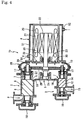
- FIG. 4 shows a two-stage screw compressor 1b according to a third embodiment of the present invention.
- the communication hole 53 is not provided, and the jacket 51 is isolated from the connection space 27.
- the jacket 51 is includes a flow-out flow passage 54 which serves as a flow outlet of a fluid introduced from the motor flow passage 52.
- a fluid different from the fluid to be compressed by the two-stage screw compressor 1b can be introduced into the jacket 51, and is caused to cool the motor 4.
- the fluid to be compressed by the two-stage screw compressor 1b may be introduced into the jacket 51, and the fluid flowing out the flow-out flow passage 54 may be fed to the inlet flow passage 9 of the two-stage screw compressor 1b.
- the box body 28 for forming the connection space 27 may be formed integrally with the casing 5 of the first-stage compressor 2 and/or the second-stage compressor 3.
Landscapes
- Engineering & Computer Science (AREA)
- Mechanical Engineering (AREA)
- General Engineering & Computer Science (AREA)
- Physics & Mathematics (AREA)
- Thermal Sciences (AREA)
- Applications Or Details Of Rotary Compressors (AREA)
Applications Claiming Priority (1)
| Application Number | Priority Date | Filing Date | Title |
|---|---|---|---|
| JP2008124680A JP5197141B2 (ja) | 2008-05-12 | 2008-05-12 | 2段スクリュ圧縮機および冷凍装置 |
Publications (3)
| Publication Number | Publication Date |
|---|---|
| EP2119915A2 EP2119915A2 (en) | 2009-11-18 |
| EP2119915A3 EP2119915A3 (en) | 2014-04-30 |
| EP2119915B1 true EP2119915B1 (en) | 2016-11-30 |
Family
ID=40874631
Family Applications (1)
| Application Number | Title | Priority Date | Filing Date |
|---|---|---|---|
| EP09154907.1A Ceased EP2119915B1 (en) | 2008-05-12 | 2009-03-11 | Two-stage screw compressor and refrigerating device |
Country Status (5)
| Country | Link |
|---|---|
| US (1) | US8205469B2 (zh) |
| EP (1) | EP2119915B1 (zh) |
| JP (1) | JP5197141B2 (zh) |
| KR (1) | KR101143166B1 (zh) |
| CN (1) | CN101581304B (zh) |
Families Citing this family (26)
| Publication number | Priority date | Publication date | Assignee | Title |
|---|---|---|---|---|
| JP5192440B2 (ja) * | 2009-05-15 | 2013-05-08 | 株式会社神戸製鋼所 | モータ及びこれを備えた圧縮機 |
| JP5334801B2 (ja) * | 2009-11-04 | 2013-11-06 | 株式会社神戸製鋼所 | 2段スクリュ圧縮機および冷凍装置 |
| AU2012309143A1 (en) * | 2011-09-16 | 2014-05-01 | Danfoss Turbocor Compressors B.V. | Motor cooling and sub-cooling circuits for compressor |
| US9856781B2 (en) | 2011-09-30 | 2018-01-02 | Eaton Corporation | Supercharger assembly with independent superchargers and motor/generator |
| US9534531B2 (en) | 2011-09-30 | 2017-01-03 | Eaton Corporation | Supercharger assembly for regeneration of throttling losses and method of control |
| WO2013049439A2 (en) * | 2011-09-30 | 2013-04-04 | Eaton Corporation | Supercharger assembly with two rotor sets |
| IN2014DN07571A (zh) | 2012-03-29 | 2015-04-24 | Eaton Corp | |
| US9039396B2 (en) | 2012-07-03 | 2015-05-26 | Emerson Climate Technologies, Inc. | Piston and scroll compressor assembly |
| CN103104494A (zh) * | 2012-11-15 | 2013-05-15 | 福建雪人压缩机科技有限公司 | 一种制冷螺杆压缩机能调位置指示装置 |
| WO2014134058A1 (en) | 2013-02-26 | 2014-09-04 | Emerson Climate Technologies, Inc. | System including high-side and low-side compressors |
| EP3674123A3 (en) | 2013-03-12 | 2020-12-09 | Eaton Corporation | Adaptive state of charge regulation and control of variable speed hybrid electric supercharger assembly for efficient vehicle operation |
| JP5891192B2 (ja) | 2013-03-25 | 2016-03-22 | 株式会社神戸製鋼所 | 発電装置及び発電システム |
| CN103195481B (zh) * | 2013-03-25 | 2015-07-29 | 上海维尔泰克螺杆机械有限公司 | 一种螺杆膨胀发电装置、有机朗肯循环发电系统 |
| WO2015077275A1 (en) | 2013-11-25 | 2015-05-28 | The Coca-Cola Company | Compressor with an oil separator |
| DE102014107126A1 (de) * | 2014-05-20 | 2015-11-26 | Harald Wenzel | Mehrstufige Verdichteranlage zur Erzeugung eines komprimierten Gase |
| DE102014017075B4 (de) * | 2014-11-20 | 2017-11-02 | Itt Bornemann Gmbh | Vorrichtung zum Fördern eines Mediums |
| JP6511321B2 (ja) * | 2015-04-10 | 2019-05-15 | 株式会社日立産機システム | 給油式容積型圧縮機 |
| TWM515035U (zh) * | 2015-09-23 | 2016-01-01 | 復盛股份有限公司 | 水潤滑雙螺旋式壓縮系統 |
| JP6573543B2 (ja) * | 2015-12-17 | 2019-09-11 | 株式会社神戸製鋼所 | スクリュ圧縮機 |
| JP6581897B2 (ja) * | 2015-12-25 | 2019-09-25 | 株式会社神戸製鋼所 | スクリュ圧縮機 |
| CN105715548A (zh) * | 2016-04-01 | 2016-06-29 | 浙江开山凯文螺杆机械有限公司 | 带柔性滑阀的两级螺杆压缩机 |
| JP7025227B2 (ja) * | 2018-01-25 | 2022-02-24 | コベルコ・コンプレッサ株式会社 | 冷凍装置 |
| BE1026195B1 (nl) * | 2018-04-11 | 2019-11-12 | Atlas Copco Airpower Naamloze Vennootschap | Vloeistof geïnjecteerde compressorinrichting |
| US10876768B2 (en) * | 2018-09-21 | 2020-12-29 | Denso International America, Inc. | Screw compressor for HVAC |
| BE1027496B1 (nl) * | 2019-08-12 | 2021-03-16 | Atlas Copco Airpower Nv | Compressorinrichting |
| CN110792595A (zh) * | 2019-11-22 | 2020-02-14 | 上海开山能源装备有限公司 | 复叠式两级螺杆压缩机 |
Family Cites Families (21)
| Publication number | Priority date | Publication date | Assignee | Title |
|---|---|---|---|---|
| GB1361604A (en) * | 1970-07-09 | 1974-07-30 | Svenska Rotor Maskiner Ab | Meshing screw rotor positive-displacement machines |
| US3779675A (en) * | 1972-07-31 | 1973-12-18 | Demag Drucklufttech | Drive system for a plurality of worm driven compressors |
| US3922114A (en) * | 1974-07-19 | 1975-11-25 | Dunham Bush Inc | Hermetic rotary helical screw compressor with improved oil management |
| US4123203A (en) * | 1977-10-14 | 1978-10-31 | Gardner-Denver Company | Multistage helical screw compressor with liquid injection |
| JP2616922B2 (ja) * | 1987-05-22 | 1997-06-04 | 株式会社日立製作所 | スクリユー圧縮機 |
| JP2768004B2 (ja) * | 1990-11-21 | 1998-06-25 | 松下電器産業株式会社 | ロータリ式多段気体圧縮機 |
| JPH0587076A (ja) * | 1991-09-27 | 1993-04-06 | Ebara Corp | スクリユー式真空ポンプ |
| JPH0658278A (ja) * | 1992-08-05 | 1994-03-01 | Ebara Corp | 多段スクリュー式真空ポンプ |
| JP3499162B2 (ja) | 1999-08-25 | 2004-02-23 | 株式会社神戸製鋼所 | 油冷式スクリュ圧縮機 |
| DE10156180B4 (de) * | 2001-11-15 | 2015-10-15 | Oerlikon Leybold Vacuum Gmbh | Gekühlte Schraubenvakuumpumpe |
| US6631617B1 (en) * | 2002-06-27 | 2003-10-14 | Tecumseh Products Company | Two stage hermetic carbon dioxide compressor |
| KR20040086892A (ko) * | 2003-03-22 | 2004-10-13 | 삼성전자주식회사 | 로터리압축기 |
| JP2004343857A (ja) * | 2003-05-14 | 2004-12-02 | Kobe Steel Ltd | 液冷式モータ |
| JP2005188326A (ja) * | 2003-12-24 | 2005-07-14 | Toyota Industries Corp | 流体圧縮機 |
| JP2006299919A (ja) * | 2005-04-20 | 2006-11-02 | Kobe Steel Ltd | スクリュ圧縮機 |
| KR100829665B1 (ko) | 2005-07-06 | 2008-05-16 | 가부시키가이샤 고베 세이코쇼 | 2단형 스크류 압축기 |
| JP2007017104A (ja) | 2005-07-08 | 2007-01-25 | Kobe Steel Ltd | スクリュ冷凍装置 |
| FI20050866A0 (fi) * | 2005-08-31 | 2005-08-31 | Axco Motors Oy | Aggregaatin jäähdytysjärjestelmä |
| KR100798559B1 (ko) * | 2005-10-17 | 2008-01-28 | 가부시키가이샤 고베 세이코쇼 | 2단 스크류 압축기 및 그것을 이용한 2단 압축 냉동기 |
| JP5033351B2 (ja) | 2006-05-10 | 2012-09-26 | 日立アプライアンス株式会社 | 冷媒用密閉形圧縮機 |
| JP5014880B2 (ja) * | 2007-05-31 | 2012-08-29 | 株式会社前川製作所 | 単機スクリュー式多段圧縮機およびそれを用いた冷凍・冷却システム |
-
2008
- 2008-05-12 JP JP2008124680A patent/JP5197141B2/ja active Active
-
2009
- 2009-03-11 EP EP09154907.1A patent/EP2119915B1/en not_active Ceased
- 2009-03-12 US US12/402,674 patent/US8205469B2/en active Active
- 2009-05-11 KR KR1020090040530A patent/KR101143166B1/ko not_active IP Right Cessation
- 2009-05-12 CN CN200910141209.9A patent/CN101581304B/zh active Active
Non-Patent Citations (1)
| Title |
|---|
| None * |
Also Published As
| Publication number | Publication date |
|---|---|
| KR101143166B1 (ko) | 2012-05-11 |
| JP5197141B2 (ja) | 2013-05-15 |
| EP2119915A3 (en) | 2014-04-30 |
| US8205469B2 (en) | 2012-06-26 |
| JP2009275517A (ja) | 2009-11-26 |
| US20090277215A1 (en) | 2009-11-12 |
| CN101581304A (zh) | 2009-11-18 |
| EP2119915A2 (en) | 2009-11-18 |
| KR20090117988A (ko) | 2009-11-17 |
| CN101581304B (zh) | 2014-06-25 |
Similar Documents
| Publication | Publication Date | Title |
|---|---|---|
| EP2119915B1 (en) | Two-stage screw compressor and refrigerating device | |
| RU2587015C2 (ru) | Винтовой компрессор | |
| KR100843460B1 (ko) | 스크롤 유체기계 | |
| US7713040B2 (en) | Rotor shaft sealing method and structure of oil-free rotary compressor | |
| KR100829665B1 (ko) | 2단형 스크류 압축기 | |
| KR100372045B1 (ko) | 모터를효과적으로냉각시킬수있는스크롤압축기 | |
| RU2689237C2 (ru) | Винтовой компрессор | |
| JP4048078B2 (ja) | ターボ圧縮機 | |
| WO2018047587A1 (ja) | オイルフリースクリュ圧縮機 | |
| US6093007A (en) | Multi-rotor helical-screw compressor with thrust balance device | |
| CN101963162B (zh) | 涡轮压缩机以及冷冻机 | |
| US4957417A (en) | Vertical oilless screw vacuum pump | |
| CN101963160B (zh) | 涡轮压缩机及冷冻机 | |
| KR20070081636A (ko) | 공기 압축/팽창기 | |
| JP2005146967A (ja) | 空気圧縮機 | |
| JP2008164095A (ja) | 磁気カップリング装置 | |
| JP5334801B2 (ja) | 2段スクリュ圧縮機および冷凍装置 | |
| WO1997009534A1 (fr) | Compresseur a haute pression de type dome | |
| JP2005171959A (ja) | モータ一体型燃料ガス圧縮機の軸封機構 | |
| JP2014074350A (ja) | スクリュ圧縮機および圧縮装置 | |
| JP4119757B2 (ja) | モータ一体型圧縮機 | |
| JP2572535B2 (ja) | 冷凍機用キャンドモータ冷却装置 | |
| JPH03124990A (ja) | 密閉形油冷式圧縮機 | |
| JP4314132B2 (ja) | エンジン駆動型オイルフリー圧縮機 | |
| JP2591612Y2 (ja) | 2段形スクリュ圧縮機 |
Legal Events
| Date | Code | Title | Description |
|---|---|---|---|
| PUAI | Public reference made under article 153(3) epc to a published international application that has entered the european phase |
Free format text: ORIGINAL CODE: 0009012 |
|
| 17P | Request for examination filed |
Effective date: 20090311 |
|
| AK | Designated contracting states |
Kind code of ref document: A2 Designated state(s): AT BE BG CH CY CZ DE DK EE ES FI FR GB GR HR HU IE IS IT LI LT LU LV MC MK MT NL NO PL PT RO SE SI SK TR |
|
| AX | Request for extension of the european patent |
Extension state: AL BA RS |
|
| PUAL | Search report despatched |
Free format text: ORIGINAL CODE: 0009013 |
|
| AK | Designated contracting states |
Kind code of ref document: A3 Designated state(s): AT BE BG CH CY CZ DE DK EE ES FI FR GB GR HR HU IE IS IT LI LT LU LV MC MK MT NL NO PL PT RO SE SI SK TR |
|
| AX | Request for extension of the european patent |
Extension state: AL BA RS |
|
| RIC1 | Information provided on ipc code assigned before grant |
Ipc: F04C 18/16 20060101AFI20140321BHEP Ipc: F04C 29/00 20060101ALI20140321BHEP Ipc: F04C 23/00 20060101ALI20140321BHEP |
|
| AKX | Designation fees paid |
Designated state(s): DE FR |
|
| AXX | Extension fees paid |
Extension state: BA Extension state: AL Extension state: RS |
|
| GRAP | Despatch of communication of intention to grant a patent |
Free format text: ORIGINAL CODE: EPIDOSNIGR1 |
|
| RIC1 | Information provided on ipc code assigned before grant |
Ipc: F25B 31/00 20060101ALN20160706BHEP Ipc: F04C 29/04 20060101ALI20160706BHEP Ipc: F04C 18/16 20060101AFI20160706BHEP Ipc: F04C 23/00 20060101ALI20160706BHEP Ipc: F25B 1/047 20060101ALN20160706BHEP Ipc: F25B 1/10 20060101ALN20160706BHEP |
|
| INTG | Intention to grant announced |
Effective date: 20160809 |
|
| GRAS | Grant fee paid |
Free format text: ORIGINAL CODE: EPIDOSNIGR3 |
|
| GRAA | (expected) grant |
Free format text: ORIGINAL CODE: 0009210 |
|
| AK | Designated contracting states |
Kind code of ref document: B1 Designated state(s): DE FR |
|
| REG | Reference to a national code |
Ref country code: DE Ref legal event code: R096 Ref document number: 602009042726 Country of ref document: DE |
|
| REG | Reference to a national code |
Ref country code: FR Ref legal event code: PLFP Year of fee payment: 9 |
|
| REG | Reference to a national code |
Ref country code: DE Ref legal event code: R097 Ref document number: 602009042726 Country of ref document: DE |
|
| PLBE | No opposition filed within time limit |
Free format text: ORIGINAL CODE: 0009261 |
|
| STAA | Information on the status of an ep patent application or granted ep patent |
Free format text: STATUS: NO OPPOSITION FILED WITHIN TIME LIMIT |
|
| 26N | No opposition filed |
Effective date: 20170831 |
|
| REG | Reference to a national code |
Ref country code: FR Ref legal event code: PLFP Year of fee payment: 10 |
|
| PGFP | Annual fee paid to national office [announced via postgrant information from national office to epo] |
Ref country code: DE Payment date: 20180227 Year of fee payment: 10 |
|
| PGFP | Annual fee paid to national office [announced via postgrant information from national office to epo] |
Ref country code: FR Payment date: 20180223 Year of fee payment: 10 |
|
| REG | Reference to a national code |
Ref country code: DE Ref legal event code: R119 Ref document number: 602009042726 Country of ref document: DE |
|
| PG25 | Lapsed in a contracting state [announced via postgrant information from national office to epo] |
Ref country code: DE Free format text: LAPSE BECAUSE OF NON-PAYMENT OF DUE FEES Effective date: 20191001 |
|
| PG25 | Lapsed in a contracting state [announced via postgrant information from national office to epo] |
Ref country code: FR Free format text: LAPSE BECAUSE OF NON-PAYMENT OF DUE FEES Effective date: 20190331 |