EP2105534B1 - Schranke - Google Patents
Schranke Download PDFInfo
- Publication number
- EP2105534B1 EP2105534B1 EP08009884.1A EP08009884A EP2105534B1 EP 2105534 B1 EP2105534 B1 EP 2105534B1 EP 08009884 A EP08009884 A EP 08009884A EP 2105534 B1 EP2105534 B1 EP 2105534B1
- Authority
- EP
- European Patent Office
- Prior art keywords
- locking bar
- light
- emitting diodes
- electronic module
- barrier
- Prior art date
- Legal status (The legal status is an assumption and is not a legal conclusion. Google has not performed a legal analysis and makes no representation as to the accuracy of the status listed.)
- Not-in-force
Links
Images

Classifications
-
- E—FIXED CONSTRUCTIONS
- E01—CONSTRUCTION OF ROADS, RAILWAYS, OR BRIDGES
- E01F—ADDITIONAL WORK, SUCH AS EQUIPPING ROADS OR THE CONSTRUCTION OF PLATFORMS, HELICOPTER LANDING STAGES, SIGNS, SNOW FENCES, OR THE LIKE
- E01F13/00—Arrangements for obstructing or restricting traffic, e.g. gates, barricades ; Preventing passage of vehicles of selected category or dimensions
- E01F13/04—Arrangements for obstructing or restricting traffic, e.g. gates, barricades ; Preventing passage of vehicles of selected category or dimensions movable to allow or prevent passage
- E01F13/06—Arrangements for obstructing or restricting traffic, e.g. gates, barricades ; Preventing passage of vehicles of selected category or dimensions movable to allow or prevent passage by swinging into open position about a vertical or horizontal axis parallel to the road direction, i.e. swinging gates
Definitions
- the invention relates to a barrier according to the preamble of claim 1.
- the object of the invention is to develop the locking bar for advertising purposes.
- the blocking bar is designed as a translucent tube.
- the barrier bar can be formed by a straight continuous tube or be formed as a buckling tree, so have two or more articulated interconnected pipe sections.
- the translucent tube may be transparent or opaque, that is translucent. It is preferably made of plastic, z. As polyester or polycarbonate, in particular fiber-reinforced plastic.
- the equipped with the LEDs (LEDs) band can be a hose or LED light bar, so z. B. be a rigid or flexible board. Multicolor or so-called red / green / blue or RGB LEDs are used.
- the band equipped with the LEDs extends essentially over the entire length of the barrier bar, ie over at least one 3 4 his length.
- the distance of the LEDs in the longitudinal direction of the barrier bar can, for. B. 1 to 10 cm from each other.
- the LED strip can be inserted into the tubular barrier bar, at least one end, preferably the end remote from the console of the locking bar z. B. with a cap, a stopper or the like closed.
- the LEDs are controlled according to the invention by an electronic module.
- the electronic module is designed so that the LEDs can be controlled in different operating modes.
- the colors can be manually adjustable or variably preprogrammed to produce different color modes of operation.
- switches or similar actuators may be provided on the electronic module.
- the RGB LEDs can be used to create any color.
- the electronics module can control the LEDs as running and / or flashing light.
- the barrier according to the invention is provided with a device for detecting the position of the barrier bar, the z. B. can be integrated into the electronic module. With this Device can be determined whether the locking bar is in the locked position, the closed position and optionally in an intermediate position.
- the barrier according to the invention also has a proximity sensor which can be arranged in the blocking bar or electronic module z. B. via the console controls, for example, in an induction loop in the road as a proximity sensor for a vehicle.
- the electronic module the LEDs only in the traffic light mode, optionally with the mentioned color gradient controls when the proximity sensor detects a vehicle while the LEDs are otherwise operated with a different color mode, eg. For example, in a company parking lot with the corporate identity colors of the company.
- the locking bar can be mounted horizontally displaceable on the console; normally, however, it is articulated pivotably on the console about a horizontal axis.
- the power supply z.
- a battery may be provided in the locking bar.
- the Electronic module in the barrier bar the power supplied via the console.
- the journal may be provided on the end facing the bearing shell with a supply board to which the external power supply is connected, wherein the supply board is in contact with a control board, which is arranged on the opposite end face of the bearing shell.
- the contacts may be designed to be circular sector-shaped to the pivot axis or circular-sector-shaped on a circuit board and at the other z. B. the supply board z. B. punctiform, ie z. B. as spring-loaded contact pins.
- the supply board and the control board may have other contacts to control the LEDs in the locking bar with the electronic module received by the console.
- the barrier 1 on a barrier bar 2, which is articulated 29enkbar on a barrier foot or console 3 about a horizontal axis 4 extending in the direction of travel.
- the barrier for example, a parking barrier z. B. at the entrance or exit of a parking area.
- the barrier bar 2 is designed as a translucent, oval in cross-section tube.
- the pipe wall 5 z. B. consist of a transparent plastic or the like.
- band 7 is arranged in the form of a circuit board. This in FIG. 1 Dashed band 7 shown with the LEDs extends over the entire length of the locking bar 2, ie of the receptacle 8, with the locking bar 2 is hinged to the console 3, to the free end of the locking bar 2, which is closed with a plug 9 ,
- a guide 11 is provided in the barrier bar 2, which is also translucent or transparent and may consist of the same material as the tube wall 5.
- the LEDs 6 on the belt 7, which are formed as RGB LEDs, are driven by an electronic module 12, which is formed in the tube from which the barrier bar 2 is formed in the region of Recording 8 is arranged.
- the locking bar 2 has a lip 13 made of a rubber-elastic material.
- the receptacle 8 is formed by two halves 14, 15, between which the pipe is clamped, of which the barrier bar 2 consists.
- the halves 14, 15 are held together with bolts 16, 17.
- the half 14 of the receptacle 8 forms the bearing shell, with which the locking bar 2 is rotatably connected to the axle or shaft journal 18, which protrudes into the bearing shell 14.
- connection bolts 19, 20 are provided which pass through the bearing shell 14 and the pin 18 radially.
- the axle or shaft journal 18 is driven to open the locking bar 2 by a motor, not shown, in the console 3.
- the contact 23 forms the z. B. + 12 or + 24V pole
- the contact 25 is grounded and the contact 24 serves as a barrier rupture sensor.
- the supply line in the console 3 to the contacts 23 and 25 is denoted by "26" and is guided by a coaxial bore 21 in the pin 18 to the board 22.
- the cable for the barrier rupture sensor is designated "35".
- a contact board 27 is arranged in the bearing shell 14, the two circular sector-shaped contacts 28, 29 which are arranged coaxially on the disk-shaped board 27.
- the circular sector-shaped contact 28 with the point-shaped contact 23 and the circular sector-shaped contact 29 with the two point-shaped contacts 24 and 25 in connection normally connects the contacts 24 and 25 of the supply board 22.
- the locking bar 2 is moved, for. B. tilted by a vehicle forward, the connection is interrupted and thus signals a barrier break.
- the contacts 28 and 29 are connected via the lines 31, 32 to the electric module 12, which are guided through the coaxial opening 36 and an opening aligned therewith in the bearing shell 14.
Landscapes
- Engineering & Computer Science (AREA)
- Architecture (AREA)
- Civil Engineering (AREA)
- Structural Engineering (AREA)
- Road Signs Or Road Markings (AREA)
- Non-Portable Lighting Devices Or Systems Thereof (AREA)
- Refuge Islands, Traffic Blockers, Or Guard Fence (AREA)
- Illuminated Signs And Luminous Advertising (AREA)
- Led Device Packages (AREA)
- Traffic Control Systems (AREA)
- Arrangements Of Lighting Devices For Vehicle Interiors, Mounting And Supporting Thereof, Circuits Therefore (AREA)
Description
- Die Erfindung bezieht sich auf eine Schranke nach dem Oberbegriff des Anspruchs 1.
- Eine solche Schranke ist in
US 7 258 461 B1 offenbart. Es ist daher bekannt, am Sperrbalken einer Schranke rot und grün leuchtende LEDs zu befestigen, um die Offen- und Sperrposition anzuzeigen. Die LEDs können leicht beschädigt werden. Sie sind daher auch nur an einzelnen Stellen am Sperrbalken angebracht und damit insgesamt nicht gut sichtbar. Auch können sie nur von einer Seite des Sperrbalkens gesehen werden. - Aufgabe der Erfindung ist es, den Sperrbalken für Reklame-Zwecke weiterzubilden.
- Dies wird erfindungsgemäß mit der im Anspruch 1 gekennzeichneten Schranke erreicht. In den Unteransprüchen sind bevorzugte Ausgestaltungen der erfindungsgemäßen Schranke wiedergegeben.
- Erfindungsgemäß ist der Sperrbalken als lichtdurchlässiges Rohr ausgebildet.
- Der Sperrbalken kann dabei durch ein gerades durchgehendes Rohr gebildet werden oder als Knickbaum ausgebildet sein, also zwei oder mehr gelenkig miteinander verbundene Rohrabschnitte aufweisen.
- Das lichtdurchlässige Rohr kann transparent oder opak, also durchscheinend sein. Vorzugsweise besteht es aus Kunststoff, z. B. Polyester oder Polycarbonat, insbesondere faserverstärktem Kunststoff.
- Das mit den Leuchtdioden (LEDs) bestückte Band kann ein Schlauch oder eine LED-Lichtleiste, also z. B. eine starre oder flexible Platine sein. Multicolor- oder sogenannte Rot/Grün/Blau oder RGB-LEDs werden verwendet.
- Das mit den LEDs bestückte Band erstreckt sich erfindungsgemäß im Wesentlichen über die gesamte Länge des Sperrbalkens, d. h. über wenigstens

- Damit das LED-Band in den rohrförmigen Sperrbalken eingeführt werden kann, ist wenigstens ein Ende, vorzugsweise das von der Konsole abgewandte Ende des Sperrbalkens z. B. mit einer Kappe, einem Stopfen oder dergleichen verschließbar.
- Die LEDs werden erfindungsgemäß durch ein Elektronikmodul angesteuert. Das Elektronikmodul ist so ausgebildet, dass die LEDs in unterschiedlichen Betriebsmodi angesteuert werden können. Bei RGB-LEDs können die Farben manuell einstellbar oder variabel vorprogrammierbar sein, um verschiedene Farbbetriebsmodi hervorzubringen. Dazu können an dem Elektronikmodul Schalter oder dergleichen Stellglieder vorgesehen sein. Durch die RGB-LEDs kann jede Farbe erzeugt werden. Auch kann das Elektronikmodul die LEDs als Lauf- und/oder Blinklicht ansteuern.
- Die erfindungsgemäße Schranke ist mit einer Einrichtung zur Positionserkennung des Sperrbalkens versehen, die z. B. in das Elektronikmodul integriert sein kann. Mit dieser Einrichtung kann festgestellt werden, ob sich der Sperrbalken in der Sperrposition, der Schließposition und gegebenenfalls in einer Zwischenposition befindet. Damit ist z. B. ein Ampel-Modus möglich. Das heißt, die LEDs leuchten bei geschlossenem Sperrbalken rot und bei offenem Sperrbalken grün. Es ist mit den RGB-LEDs und durch dessen Ansteuerung mit dem Elektronikmodul, z. B. auch ein Farbverlauf von rot, z. B. über orange und/oder gelb nach grün möglich.
- Die erfindungsgemäße Schranke weist zudem einen Näherungssensor auf, der in dem Sperrbalken angeordnet sein kann oder Elektronikmodul z. B. über die Konsole ansteuert, beispielsweise bei einer Induktionsschleife in der Fahrbahn als Näherungssensor für ein Fahrzeug.
- Damit ist es möglich, dass das Elektronikmodul die LEDs nur dann im Ampelmodus, gegebenenfalls mit dem erwähnten Farbverlauf ansteuert, wenn der Näherungssensor ein Fahrzeug erfasst, während die LEDs ansonsten mit einem anderen Farbmodus betrieben werden, z. B. bei einem Firmenparkplatz mit den "Corporate Identity"-Farben des Unternehmens.
- Der Sperrbalken kann waagrecht verschiebbar an der Konsole gelagert sein; normalerweise ist er jedoch an der Konsole um eine waagrechte Achse verschwenkbar angelenkt.
- Dabei ist es möglich, neben dem LED-Band auch das Elektronikmodul in dem rohrförmigen Sperrbalken anzuordnen, vorzugsweise in einem nicht sichtbaren Bereich, also im Bereich der Lagerschale, mit der der Sperrbalken am Wellen- oder Achszapfen der Konsole angelenkt ist.
- Zwar kann dann auch die Stromversorgung, z. B. eine Batterie, in dem Sperrbalken vorgesehen sein. Vorzugsweise wird dem Elektronikmodul in dem Sperrbalken jedoch der Strom über die Konsole zugeführt. Dazu kann der Achszapfen an der der Lagerschale zugewandten Stirnseite mit einer Versorgungsplatine versehen sein, an die die externe Stromzuführung angeschlossen ist, wobei die Versorgungsplatine mit einer Kontrollplatine in Kontakt steht, die an der gegenüberliegenden Stirnseite der Lagerschale angeordnet ist.
- Die Kontakte können dabei zur Schwenkachse kreissektorförmig ausgebildet sein oder an einer Platine kreissektorförmig und an der anderen z. B. der Versorgungsplatine z. B. punktförmig, also z. B. als federbelastete Kontaktstifte.
- Auch ist es möglich, das Elektronikmodul in oder an der Konsole vorzusehen. Dadurch wird der Vorteil erzielt, dass die Elektronik nicht beschädigt wird, wenn der Sperrbalken z. B. durch ein Fahrzeug zerstört wird.
- In diesem Fall können die Versorgungsplatine und die Kontrollplatine noch weitere Kontakte aufweisen, um die Leuchtdioden in dem Sperrbalken mit dem von der Konsole aufgenommene Elektronikmodul anzusteuern.
- Nachstehend ist die Erfindung anhand der beigefügten Zeichnung beispielhaft näher erläutert. Darin zeigen jeweils schematisch:
-
Figur 1 eine Vorderansicht einer Schranke mit den Sperrbalken in der Schließstellung mit weggebrochenen Teilen; -
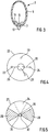
Figur 2 einen Schnitt durch den Sperrbalken und dessen Aufnahme entlang der Linie II-II nachFigur 1 ; -
Figur 3 einen Schnitt entlang der Linie III-III nachFigur 1 ; und -
Figur 4 und 5 eine Draufsicht auf die Versorgungsplatine bzw. die der Versorgungsplatine gegenüberliegende Seite der Kontaktplatine nachFigur 2 . - Gemäß
Figuren 1 bis 3 weist die Schranke 1 einen Sperrbalken 2 auf, der an einem Schrankenfuß oder Konsole 3 um eine in Fahrtrichtung verlaufende waagrechte Achse 4 verschenkbar angelenkt ist. Die Schranke 1 kann beispielsweise eine Parkschranke z. B. an der Zu- oder Ausfahrt einer Parkfläche sein. - Der Sperrbalken 2 ist als durchscheinendes, im Querschnitt ovales Rohr ausgebildet. Dazu kann die Rohrwand 5 z. B. aus einem transparenten Kunststoff oder dergleichen bestehen.
- In dem Sperrbalken 2 ist ein mit LEDs 6 bestücktes Band 7 in Form einer Platine angeordnet. Das in
Figur 1 gestrichelt dargestellte Band 7 mit den LEDs erstreckt sich über die gesamte Länge des Sperrbalkens 2, d. h. von der Aufnahme 8, mit der der Sperrbalken 2 an der Konsole 3 angelenkt ist, bis zum freien Ende des Sperrbalkens 2, das mit einem Stopfen 9 verschlossen ist. - Um das Band 7 zu fixieren, ist im Sperrbalken 2 eine Führung 11 vorgesehen, die gleichfalls durchscheinend oder transparent ist und aus dem gleichen Material wie die Rohrwand 5 bestehen kann.
- Die LEDs 6 auf dem Band 7, die als RGB-LEDs ausgebildet sind, werden mit einem Elektronikmodul 12 angesteuert, das in dem Rohr, aus dem der Sperrbalken 2 gebildet wird, im Bereich der Aufnahme 8 angeordnet ist. An der Unterseite weist der Sperrbalken 2 eine Lippe 13 aus einem gummielastischem Material auf.
- Die Aufnahme 8 wird durch zwei Hälften 14, 15 gebildet, zwischen denen das Rohr eingespannt ist, aus dem der Sperrbalken 2 besteht. Die Hälften 14, 15 werden mit Schraubbolzen 16, 17 zusammengehalten. Die Hälfte 14 der Aufnahme 8 bildet die Lagerschale, mit der der Sperrbalken 2 am Achs- bzw. Wellenzapfen 18 drehfest verbunden ist, der in die Lagerschale 14 ragt.
- Zur drehfesten Verbindung sind Schraubbolzen 19, 20 vorgesehen, die die Lagerschale 14 und den Zapfen 18 radial durchsetzen. Der Achs- oder Wellenzapfen 18 wird zum Öffnen des Sperrbalkens 2 von einem nicht dargestellten Motor in der Konsole 3 angetrieben.
- An der der Aufnahme 8 zugewandten Stirnseite ist der Zapfen 18 mit einer Versorgungsplatine 22 versehen, die federbelastete Kontaktstifte 23, 24 und 25 aufweist, wie insbesondere aus
Figur 4 ersichtlich. - Dabei bildet der Kontakt 23 den z. B. +12- oder +24V-Pol, der Kontakt 25 ist geerdet und der Kontakt 24 dient als Schrankenbruchsensor. Die Versorgungsleitung in der Konsole 3 zu den Kontakten 23 und 25 ist mit "26" bezeichnet und wird durch eine koaxiale Bohrung 21 in dem Zapfen 18 zur Platine 22 geführt. Die Leitung für den Schrankenbruchsensor ist mit "35" bezeichnet.
- Gegenüber der Versorgungsplatine 22 ist in der Lageschale 14 eine Kontaktplatine 27 angeordnet, die zwei kreissektorförmige Kontakte 28, 29 aufweist, die koaxial auf der scheibenförmigen Platine 27 angeordnet sind.
- Dabei steht der kreissektorförmige Kontakt 28 mit dem punktförmigen Kontakt 23 und der kreissektorförmige Kontakt 29 mit den beiden punktförmigen Kontakten 24 und 25 in Verbindung. Das heißt, der Kontakt 29 verbindet im Normalfall die Kontakte 24 und 25 der Versorgungsplatine 22. Wird der Sperrbalken 2 jedoch verschoben, z. B. durch ein Fahrzeug nach vorne gekippt, wird die Verbindung unterbrochen und damit ein Schrankenbruch signalisiert.
- Die Kontakte 28 und 29 sind über die Leitungen 31, 32 mit dem Elektromodul 12 verbunden, die durch die koaxiale Öffnung 36 und eine damit fluchtende Öffnung in der Lagerschale 14 hindurch geführt sind.
- Wenn das Elektronikmodul in der Konsole 3 angeordnet ist, sind zur Ansteuerung der LEDs 6 weitere Kontakte 33, 34 an der Versorgungsplatine 22 bzw. der Kontaktplatine 22 vorgesehen, die in
Figur 4 und 5 gestrichelt dargestellt sind. - Anstelle des Kreissektors ist auch eine andere flächige Ausbildung der Kontakte 28, 29, 34 möglich, die mit den punktförmigen Kontakten 23 bis 25 und 33 in Kontakt stehen.
Claims (7)
- Schranke mit einem Sperrbalken (2), der an einer Konsole (3) zwischen einer Offen- und einer Sperrposition beweglich gelagert ist, wobei der Sperrbalken (2) als lichtdurchlässiges Rohr ausgebildet ist, in dem eine Beleuchtungseinrichtung angeordnet ist, wobei die Beleuchtungseinrichtung durch ein mit Leuchtdioden (6) bestücktes Band (7) gebildet wird, das sich im Wesentlichen über die gesamte Länge des Sperrbalkens (2) erstreckt, und zur Ansteuerung der Leuchtdioden (6) ein Elektronikmodul (12) vorgesehen ist, wobei die Leuchtdioden (6) als mit dem Elektronikmodul (12) variabel ansteuerbare Rot/Grün/Blau-Leuchtdioden ausgebildet sind und eine Einrichtung zur Positionserkennung des Sperrbalkens (2) zur Ansteuerung des Elektronikmoduls (12) vorgesehen ist, um einen Ampel-Modus zu realisieren, in dem die Leuchtdioden (6) bei geschlossenem Sperrbalken (2) rot und bei offenem Sperrbalken (2) grün leuchten, dadurch gekennzeichnet, dass das Elektronikmodul (12) durch einen Fahrzeug-Näherungssensor ansteuerbar ist, wodurch die Leuchtdioden (6) nur dann im Ampel-Modus ansteuerbar sind, wenn der Näherungssensor ein Fahrzeug erfasst, wobei die Leuchtdioden (6) ansonsten mit einem anderen Farbmodus betrieben werden.
- Schranke nach Anspruch 1, dadurch gekennzeichnet, dass wenigstens ein Ende des Sperrbalkens (2) zum Einführen des mit den Leuchtdioden (6) bestückten Bandes (7) verschließbar ausgebildet ist.
- Schranke nach einem der vorstehenden Ansprüche, dadurch gekennzeichnet, dass der Sperrbalken (2) und die Konsole (3) durch einen Zapfen (18) und eine Lagerschale (14) miteinander verschwenkbar verbunden sind, wobei die Lagerschale (14) mit einer Kontaktplatine (27) und der Zapfen (18) mit einer Versorgungsplatine (22) zur Stromversorgung der Leuchtdioden (6) in dem Sperrbalken (2) versehen sind.
- Schranke nach Anspruch 3, dadurch gekennzeichnet, dass die Versorgungsplatine (22) oder die Kontaktplatine (27) mit punktförmigen Kontakten (23, 25) und die Kontaktplatine (27) bzw. die Versorgungsplatine (22) mit kreissektorförmigen Kontakten (28, 29) versehen ist.
- Schranke nach Anspruch 4, dadurch gekennzeichnet, dass die Versorgungsplatine (22) außer den beiden Kontakten (23, 25) zur Stromversorgung einen weiteren Kontakt (24) als Bruchsensor für den Sperrbalken (2) aufweist.
- Schranke nach einem der vorstehenden Ansprüche, dadurch gekennzeichnet, dass das Elektronikmodul (12) in dem Sperrbalken (2) angeordnet ist.
- Schranke nach Anspruch 4, dadurch gekennzeichnet, dass das Elektronikmodul in der Konsole (3) angeordnet ist und die Versorgungsplatine (22) und die Kontaktplatine (27) wenigstens einen weiteren punktförmigen bzw. kreissektorförmigen Kontakt (33, 34) zur Ansteuerung der Leuchtdioden (6) mit dem Elektronikmodul aufweist.
Applications Claiming Priority (1)
| Application Number | Priority Date | Filing Date | Title |
|---|---|---|---|
| DE102008016070A DE102008016070A1 (de) | 2008-03-28 | 2008-03-28 | Schranke |
Publications (3)
| Publication Number | Publication Date |
|---|---|
| EP2105534A2 EP2105534A2 (de) | 2009-09-30 |
| EP2105534A3 EP2105534A3 (de) | 2012-06-27 |
| EP2105534B1 true EP2105534B1 (de) | 2017-03-01 |
Family
ID=40801930
Family Applications (1)
| Application Number | Title | Priority Date | Filing Date |
|---|---|---|---|
| EP08009884.1A Not-in-force EP2105534B1 (de) | 2008-03-28 | 2008-05-30 | Schranke |
Country Status (5)
| Country | Link |
|---|---|
| US (1) | US8011797B2 (de) |
| EP (1) | EP2105534B1 (de) |
| JP (1) | JP5610699B2 (de) |
| DE (1) | DE102008016070A1 (de) |
| ES (1) | ES2622139T3 (de) |
Cited By (1)
| Publication number | Priority date | Publication date | Assignee | Title |
|---|---|---|---|---|
| DE202017103269U1 (de) | 2017-05-31 | 2017-08-16 | Skidata Ag | Beleuchtbarer Balken |
Families Citing this family (15)
| Publication number | Priority date | Publication date | Assignee | Title |
|---|---|---|---|---|
| DE202010006973U1 (de) | 2010-05-19 | 2010-08-19 | Scheidt & Bachmann Gmbh | Baugruppe für einen Schrankenarm |
| DE202011050275U1 (de) | 2011-05-27 | 2011-07-14 | Skidata Ag | Schranke |
| EP2597199B1 (de) | 2011-11-25 | 2013-11-13 | SkiData AG | Als Knickbaum ausgeführter Schrankenbaum einer Fahrzeugschranke |
| EP2597198A1 (de) * | 2011-11-25 | 2013-05-29 | SkiData AG | Fahrzeugschranke |
| AT13089U1 (de) * | 2011-12-14 | 2013-06-15 | Safeplast Gmbh | Leit- bzw. absperreinrichtung für verkehrsflächen |
| US9273435B2 (en) | 2012-06-01 | 2016-03-01 | GateArm Technologies, Inc. | Vehicle barrier system with illuminating gate arm |
| US8845125B1 (en) | 2012-06-01 | 2014-09-30 | GateArm Technologies, Inc. | Vehicle barrier system with illuminating gate arm and method |
| DE202015103247U1 (de) | 2015-06-19 | 2015-07-31 | Skidata Ag | Zugangskontrollvorrichtung |
| US10364950B2 (en) | 2016-05-17 | 2019-07-30 | Michael Pikman | Barrier gate arm with recessed light housing |
| US20170336039A1 (en) * | 2016-05-17 | 2017-11-23 | Michael Pikman | Barrier gate arm with recessed light housing |
| US11939732B2 (en) * | 2018-10-21 | 2024-03-26 | Fencing Supply Group Acquisition, Llc | Device for warning or barrier gate |
| USD917071S1 (en) | 2019-06-15 | 2021-04-20 | Renee Smith | Automatic barrier gate housing |
| CN112647444A (zh) * | 2019-10-10 | 2021-04-13 | 北极光电股份有限公司 | 用于光显变化的显示设备 |
| US11873609B2 (en) * | 2021-08-27 | 2024-01-16 | Jonathan Brinkman | Vehicle barrier gate arm having anti-roll end cap |
| DE102022100279A1 (de) * | 2022-01-07 | 2023-07-13 | ELKA Torantriebe GmbH u. Co. Betriebs KG | Vorrichtung zum Vereinzeln von Personen in einem Vereinzelungsbereich sowie Personenvereinzelungseinrichtung |
Family Cites Families (10)
| Publication number | Priority date | Publication date | Assignee | Title |
|---|---|---|---|---|
| JPH02109824U (de) * | 1989-02-15 | 1990-09-03 | ||
| JPH07323841A (ja) * | 1994-05-31 | 1995-12-12 | Souji Kobayashi | 遮断機バー |
| AT402311B (de) * | 1995-03-20 | 1997-04-25 | Skidata Gmbh | Absperreinrichtung |
| JP2001311123A (ja) * | 2000-05-02 | 2001-11-09 | Miyachi Kk | 交通制御装置および交通手段の自動課金装置 |
| US6472823B2 (en) * | 2001-03-07 | 2002-10-29 | Star Reach Corporation | LED tubular lighting device and control device |
| JP2005053392A (ja) * | 2003-08-06 | 2005-03-03 | Ryobi Ltd | 表示灯取付装置及びこれを内蔵した遮断バー |
| JP2006059603A (ja) * | 2004-08-18 | 2006-03-02 | Fukei Secolo:Kk | ソーラーライト |
| US7342510B2 (en) * | 2005-05-18 | 2008-03-11 | Pate Alexs D | Displaying information on a gate system |
| KR100635472B1 (ko) * | 2006-02-28 | 2006-10-18 | 대경전자기업(주) | 착탈식 주차장 차단기 |
| US7258461B1 (en) | 2007-01-07 | 2007-08-21 | Gamasonic Ltd. | Vehicle barrier with light |
-
2008
- 2008-03-28 DE DE102008016070A patent/DE102008016070A1/de not_active Withdrawn
- 2008-05-30 EP EP08009884.1A patent/EP2105534B1/de not_active Not-in-force
- 2008-05-30 ES ES08009884.1T patent/ES2622139T3/es active Active
-
2009
- 2009-03-26 US US12/383,692 patent/US8011797B2/en active Active
- 2009-03-27 JP JP2009078335A patent/JP5610699B2/ja active Active
Non-Patent Citations (1)
| Title |
|---|
| None * |
Cited By (1)
| Publication number | Priority date | Publication date | Assignee | Title |
|---|---|---|---|---|
| DE202017103269U1 (de) | 2017-05-31 | 2017-08-16 | Skidata Ag | Beleuchtbarer Balken |
Also Published As
| Publication number | Publication date |
|---|---|
| EP2105534A2 (de) | 2009-09-30 |
| JP2009245945A (ja) | 2009-10-22 |
| EP2105534A3 (de) | 2012-06-27 |
| US20090244889A1 (en) | 2009-10-01 |
| ES2622139T3 (es) | 2017-07-05 |
| JP5610699B2 (ja) | 2014-10-22 |
| DE102008016070A1 (de) | 2009-10-01 |
| US8011797B2 (en) | 2011-09-06 |
Similar Documents
| Publication | Publication Date | Title |
|---|---|---|
| EP2105534B1 (de) | Schranke | |
| EP1910871B1 (de) | Ortungsgerät | |
| DE19538770B4 (de) | Außenrückblickspiegel für Fahrzeuge, vorzugsweise für Kraftfahrzeuge | |
| DE102019120453A1 (de) | Fahrzeugbeleuchtungsbaugruppe | |
| EP1832452A2 (de) | Luftausströmer mit visueller Rückmeldung | |
| DE202019101222U1 (de) | B-Säulen-Nähewarnsystem für autonome Fahrzeuge | |
| DE102010019764A1 (de) | Leuchtfähige Fingerschutzvorrichtung für eine Tür eines Fahrzeugs und Herstellungsverfahren für eine Schutzleiste für eine leuchtfähige Fingerschutzvorrichtung | |
| DE202012103410U1 (de) | Leuchteinrichtung | |
| EP3126205B1 (de) | Beleuchtung von fahrzeugtüren | |
| DE102011112835A1 (de) | Beleuchtungsanordnung für einen Kraftwagen | |
| DE202013105390U1 (de) | Wandungselement | |
| WO2021004570A1 (de) | Aufstellvorrichtung für ein kraftfahrzeug | |
| DE202008018145U1 (de) | Schranke | |
| DE102015112041A1 (de) | Tor, insbesondere Garagentor | |
| DE102011113711B4 (de) | Vorrichtung zur Beleuchtung eines Kraftfahrzeuginnenraums | |
| DE10018800B4 (de) | Griffvorrichtung für eine Heckklappe eines Kraftfahrzeugs | |
| DE8436320U1 (de) | Beleuchteter Tastenknopf | |
| DE102015114632A1 (de) | Signalleuchte für Fahrzeuge | |
| EP2597198A1 (de) | Fahrzeugschranke | |
| DE202008018110U1 (de) | Lichtsignalisation in dem Türaußengriff eines Fahrzeugs | |
| DE202007006765U1 (de) | Beleuchtungseinrichtung für Fahrräder | |
| DE102006032023A1 (de) | Verfahren und Vorrichtung zum Beleuchten eines Kraftfahrzeuges | |
| DE20315183U1 (de) | Leuchtender Schirm, insbesondere Regenschirm | |
| EP2463156B1 (de) | Beleuchtungs-Zwischenstück | |
| DE19927752A1 (de) | Markierungseinrichtung |
Legal Events
| Date | Code | Title | Description |
|---|---|---|---|
| PUAI | Public reference made under article 153(3) epc to a published international application that has entered the european phase |
Free format text: ORIGINAL CODE: 0009012 |
|
| AK | Designated contracting states |
Kind code of ref document: A2 Designated state(s): AT BE BG CH CY CZ DE DK EE ES FI FR GB GR HR HU IE IS IT LI LT LU LV MC MT NL NO PL PT RO SE SI SK TR |
|
| AX | Request for extension of the european patent |
Extension state: AL BA MK RS |
|
| PUAL | Search report despatched |
Free format text: ORIGINAL CODE: 0009013 |
|
| AK | Designated contracting states |
Kind code of ref document: A3 Designated state(s): AT BE BG CH CY CZ DE DK EE ES FI FR GB GR HR HU IE IS IT LI LT LU LV MC MT NL NO PL PT RO SE SI SK TR |
|
| AX | Request for extension of the european patent |
Extension state: AL BA MK RS |
|
| RIC1 | Information provided on ipc code assigned before grant |
Ipc: E01F 13/06 20060101AFI20120522BHEP |
|
| 17P | Request for examination filed |
Effective date: 20120920 |
|
| AKX | Designation fees paid |
Designated state(s): AT BE BG CH CY CZ DE DK EE ES FI FR GB GR HR HU IE IS IT LI LT LU LV MC MT NL NO PL PT RO SE SI SK TR |
|
| RAP1 | Party data changed (applicant data changed or rights of an application transferred) |
Owner name: SKIDATA AG |
|
| 17Q | First examination report despatched |
Effective date: 20160202 |
|
| GRAP | Despatch of communication of intention to grant a patent |
Free format text: ORIGINAL CODE: EPIDOSNIGR1 |
|
| STAA | Information on the status of an ep patent application or granted ep patent |
Free format text: STATUS: GRANT OF PATENT IS INTENDED |
|
| INTG | Intention to grant announced |
Effective date: 20161114 |
|
| GRAS | Grant fee paid |
Free format text: ORIGINAL CODE: EPIDOSNIGR3 |
|
| GRAA | (expected) grant |
Free format text: ORIGINAL CODE: 0009210 |
|
| STAA | Information on the status of an ep patent application or granted ep patent |
Free format text: STATUS: THE PATENT HAS BEEN GRANTED |
|
| AK | Designated contracting states |
Kind code of ref document: B1 Designated state(s): AT BE BG CH CY CZ DE DK EE ES FI FR GB GR HR HU IE IS IT LI LT LU LV MC MT NL NO PL PT RO SE SI SK TR |
|
| REG | Reference to a national code |
Ref country code: GB Ref legal event code: FG4D Free format text: NOT ENGLISH |
|
| REG | Reference to a national code |
Ref country code: CH Ref legal event code: EP Ref country code: AT Ref legal event code: REF Ref document number: 871501 Country of ref document: AT Kind code of ref document: T Effective date: 20170315 |
|
| REG | Reference to a national code |
Ref country code: IE Ref legal event code: FG4D Free format text: LANGUAGE OF EP DOCUMENT: GERMAN |
|
| REG | Reference to a national code |
Ref country code: CH Ref legal event code: NV Representative=s name: LEMAN CONSULTING S.A., CH |
|
| REG | Reference to a national code |
Ref country code: DE Ref legal event code: R096 Ref document number: 502008015055 Country of ref document: DE |
|
| REG | Reference to a national code |
Ref country code: FR Ref legal event code: PLFP Year of fee payment: 10 |
|
| REG | Reference to a national code |
Ref country code: ES Ref legal event code: FG2A Ref document number: 2622139 Country of ref document: ES Kind code of ref document: T3 Effective date: 20170705 Ref country code: NL Ref legal event code: MP Effective date: 20170301 |
|
| REG | Reference to a national code |
Ref country code: LT Ref legal event code: MG4D |
|
| PG25 | Lapsed in a contracting state [announced via postgrant information from national office to epo] |
Ref country code: LT Free format text: LAPSE BECAUSE OF FAILURE TO SUBMIT A TRANSLATION OF THE DESCRIPTION OR TO PAY THE FEE WITHIN THE PRESCRIBED TIME-LIMIT Effective date: 20170301 Ref country code: FI Free format text: LAPSE BECAUSE OF FAILURE TO SUBMIT A TRANSLATION OF THE DESCRIPTION OR TO PAY THE FEE WITHIN THE PRESCRIBED TIME-LIMIT Effective date: 20170301 Ref country code: GR Free format text: LAPSE BECAUSE OF FAILURE TO SUBMIT A TRANSLATION OF THE DESCRIPTION OR TO PAY THE FEE WITHIN THE PRESCRIBED TIME-LIMIT Effective date: 20170602 Ref country code: NO Free format text: LAPSE BECAUSE OF FAILURE TO SUBMIT A TRANSLATION OF THE DESCRIPTION OR TO PAY THE FEE WITHIN THE PRESCRIBED TIME-LIMIT Effective date: 20170601 Ref country code: HR Free format text: LAPSE BECAUSE OF FAILURE TO SUBMIT A TRANSLATION OF THE DESCRIPTION OR TO PAY THE FEE WITHIN THE PRESCRIBED TIME-LIMIT Effective date: 20170301 |
|
| PG25 | Lapsed in a contracting state [announced via postgrant information from national office to epo] |
Ref country code: SE Free format text: LAPSE BECAUSE OF FAILURE TO SUBMIT A TRANSLATION OF THE DESCRIPTION OR TO PAY THE FEE WITHIN THE PRESCRIBED TIME-LIMIT Effective date: 20170301 Ref country code: BG Free format text: LAPSE BECAUSE OF FAILURE TO SUBMIT A TRANSLATION OF THE DESCRIPTION OR TO PAY THE FEE WITHIN THE PRESCRIBED TIME-LIMIT Effective date: 20170601 Ref country code: LV Free format text: LAPSE BECAUSE OF FAILURE TO SUBMIT A TRANSLATION OF THE DESCRIPTION OR TO PAY THE FEE WITHIN THE PRESCRIBED TIME-LIMIT Effective date: 20170301 Ref country code: LU Free format text: LAPSE BECAUSE OF NON-PAYMENT OF DUE FEES Effective date: 20170531 |
|
| PG25 | Lapsed in a contracting state [announced via postgrant information from national office to epo] |
Ref country code: NL Free format text: LAPSE BECAUSE OF FAILURE TO SUBMIT A TRANSLATION OF THE DESCRIPTION OR TO PAY THE FEE WITHIN THE PRESCRIBED TIME-LIMIT Effective date: 20170301 |
|
| PG25 | Lapsed in a contracting state [announced via postgrant information from national office to epo] |
Ref country code: RO Free format text: LAPSE BECAUSE OF FAILURE TO SUBMIT A TRANSLATION OF THE DESCRIPTION OR TO PAY THE FEE WITHIN THE PRESCRIBED TIME-LIMIT Effective date: 20170301 Ref country code: SK Free format text: LAPSE BECAUSE OF FAILURE TO SUBMIT A TRANSLATION OF THE DESCRIPTION OR TO PAY THE FEE WITHIN THE PRESCRIBED TIME-LIMIT Effective date: 20170301 Ref country code: EE Free format text: LAPSE BECAUSE OF FAILURE TO SUBMIT A TRANSLATION OF THE DESCRIPTION OR TO PAY THE FEE WITHIN THE PRESCRIBED TIME-LIMIT Effective date: 20170301 Ref country code: CZ Free format text: LAPSE BECAUSE OF FAILURE TO SUBMIT A TRANSLATION OF THE DESCRIPTION OR TO PAY THE FEE WITHIN THE PRESCRIBED TIME-LIMIT Effective date: 20170301 |
|
| PG25 | Lapsed in a contracting state [announced via postgrant information from national office to epo] |
Ref country code: IS Free format text: LAPSE BECAUSE OF FAILURE TO SUBMIT A TRANSLATION OF THE DESCRIPTION OR TO PAY THE FEE WITHIN THE PRESCRIBED TIME-LIMIT Effective date: 20170701 Ref country code: PL Free format text: LAPSE BECAUSE OF FAILURE TO SUBMIT A TRANSLATION OF THE DESCRIPTION OR TO PAY THE FEE WITHIN THE PRESCRIBED TIME-LIMIT Effective date: 20170301 Ref country code: PT Free format text: LAPSE BECAUSE OF FAILURE TO SUBMIT A TRANSLATION OF THE DESCRIPTION OR TO PAY THE FEE WITHIN THE PRESCRIBED TIME-LIMIT Effective date: 20170703 |
|
| REG | Reference to a national code |
Ref country code: DE Ref legal event code: R097 Ref document number: 502008015055 Country of ref document: DE |
|
| PLBE | No opposition filed within time limit |
Free format text: ORIGINAL CODE: 0009261 |
|
| STAA | Information on the status of an ep patent application or granted ep patent |
Free format text: STATUS: NO OPPOSITION FILED WITHIN TIME LIMIT |
|
| PG25 | Lapsed in a contracting state [announced via postgrant information from national office to epo] |
Ref country code: DK Free format text: LAPSE BECAUSE OF FAILURE TO SUBMIT A TRANSLATION OF THE DESCRIPTION OR TO PAY THE FEE WITHIN THE PRESCRIBED TIME-LIMIT Effective date: 20170301 Ref country code: MC Free format text: LAPSE BECAUSE OF FAILURE TO SUBMIT A TRANSLATION OF THE DESCRIPTION OR TO PAY THE FEE WITHIN THE PRESCRIBED TIME-LIMIT Effective date: 20170301 |
|
| 26N | No opposition filed |
Effective date: 20171204 |
|
| REG | Reference to a national code |
Ref country code: IE Ref legal event code: MM4A |
|
| PG25 | Lapsed in a contracting state [announced via postgrant information from national office to epo] |
Ref country code: SI Free format text: LAPSE BECAUSE OF FAILURE TO SUBMIT A TRANSLATION OF THE DESCRIPTION OR TO PAY THE FEE WITHIN THE PRESCRIBED TIME-LIMIT Effective date: 20170301 |
|
| PG25 | Lapsed in a contracting state [announced via postgrant information from national office to epo] |
Ref country code: LU Free format text: LAPSE BECAUSE OF NON-PAYMENT OF DUE FEES Effective date: 20170530 |
|
| REG | Reference to a national code |
Ref country code: BE Ref legal event code: MM Effective date: 20170531 |
|
| PG25 | Lapsed in a contracting state [announced via postgrant information from national office to epo] |
Ref country code: IE Free format text: LAPSE BECAUSE OF NON-PAYMENT OF DUE FEES Effective date: 20170530 |
|
| REG | Reference to a national code |
Ref country code: FR Ref legal event code: PLFP Year of fee payment: 11 |
|
| PG25 | Lapsed in a contracting state [announced via postgrant information from national office to epo] |
Ref country code: BE Free format text: LAPSE BECAUSE OF NON-PAYMENT OF DUE FEES Effective date: 20170531 |
|
| PG25 | Lapsed in a contracting state [announced via postgrant information from national office to epo] |
Ref country code: MT Free format text: LAPSE BECAUSE OF FAILURE TO SUBMIT A TRANSLATION OF THE DESCRIPTION OR TO PAY THE FEE WITHIN THE PRESCRIBED TIME-LIMIT Effective date: 20170301 |
|
| PG25 | Lapsed in a contracting state [announced via postgrant information from national office to epo] |
Ref country code: HU Free format text: LAPSE BECAUSE OF FAILURE TO SUBMIT A TRANSLATION OF THE DESCRIPTION OR TO PAY THE FEE WITHIN THE PRESCRIBED TIME-LIMIT; INVALID AB INITIO Effective date: 20080530 |
|
| PG25 | Lapsed in a contracting state [announced via postgrant information from national office to epo] |
Ref country code: CY Free format text: LAPSE BECAUSE OF NON-PAYMENT OF DUE FEES Effective date: 20170301 |
|
| PG25 | Lapsed in a contracting state [announced via postgrant information from national office to epo] |
Ref country code: TR Free format text: LAPSE BECAUSE OF FAILURE TO SUBMIT A TRANSLATION OF THE DESCRIPTION OR TO PAY THE FEE WITHIN THE PRESCRIBED TIME-LIMIT Effective date: 20170301 |
|
| PGFP | Annual fee paid to national office [announced via postgrant information from national office to epo] |
Ref country code: FR Payment date: 20210421 Year of fee payment: 14 Ref country code: IT Payment date: 20210422 Year of fee payment: 14 Ref country code: DE Payment date: 20210421 Year of fee payment: 14 |
|
| PGFP | Annual fee paid to national office [announced via postgrant information from national office to epo] |
Ref country code: AT Payment date: 20210422 Year of fee payment: 14 Ref country code: GB Payment date: 20210422 Year of fee payment: 14 Ref country code: ES Payment date: 20210601 Year of fee payment: 14 Ref country code: CH Payment date: 20210421 Year of fee payment: 14 |
|
| REG | Reference to a national code |
Ref country code: DE Ref legal event code: R119 Ref document number: 502008015055 Country of ref document: DE |
|
| REG | Reference to a national code |
Ref country code: CH Ref legal event code: PL |
|
| REG | Reference to a national code |
Ref country code: AT Ref legal event code: MM01 Ref document number: 871501 Country of ref document: AT Kind code of ref document: T Effective date: 20220530 |
|
| GBPC | Gb: european patent ceased through non-payment of renewal fee |
Effective date: 20220530 |
|
| PG25 | Lapsed in a contracting state [announced via postgrant information from national office to epo] |
Ref country code: LI Free format text: LAPSE BECAUSE OF NON-PAYMENT OF DUE FEES Effective date: 20220531 Ref country code: CH Free format text: LAPSE BECAUSE OF NON-PAYMENT OF DUE FEES Effective date: 20220531 Ref country code: AT Free format text: LAPSE BECAUSE OF NON-PAYMENT OF DUE FEES Effective date: 20220530 |
|
| PG25 | Lapsed in a contracting state [announced via postgrant information from national office to epo] |
Ref country code: FR Free format text: LAPSE BECAUSE OF NON-PAYMENT OF DUE FEES Effective date: 20220531 |
|
| PG25 | Lapsed in a contracting state [announced via postgrant information from national office to epo] |
Ref country code: GB Free format text: LAPSE BECAUSE OF NON-PAYMENT OF DUE FEES Effective date: 20220530 Ref country code: DE Free format text: LAPSE BECAUSE OF NON-PAYMENT OF DUE FEES Effective date: 20221201 |
|
| REG | Reference to a national code |
Ref country code: ES Ref legal event code: FD2A Effective date: 20230630 |
|
| PG25 | Lapsed in a contracting state [announced via postgrant information from national office to epo] |
Ref country code: IT Free format text: LAPSE BECAUSE OF NON-PAYMENT OF DUE FEES Effective date: 20220530 Ref country code: ES Free format text: LAPSE BECAUSE OF NON-PAYMENT OF DUE FEES Effective date: 20220531 |