EP2103407B1 - Metal/resin composite and process for producing the same - Google Patents
Metal/resin composite and process for producing the same Download PDFInfo
- Publication number
- EP2103407B1 EP2103407B1 EP07860490.7A EP07860490A EP2103407B1 EP 2103407 B1 EP2103407 B1 EP 2103407B1 EP 07860490 A EP07860490 A EP 07860490A EP 2103407 B1 EP2103407 B1 EP 2103407B1
- Authority
- EP
- European Patent Office
- Prior art keywords
- resin
- resin composition
- stainless steel
- metal
- main component
- Prior art date
- Legal status (The legal status is an assumption and is not a legal conclusion. Google has not performed a legal analysis and makes no representation as to the accuracy of the status listed.)
- Active
Links
- 229910052751 metal Inorganic materials 0.000 title claims description 80
- 238000000034 method Methods 0.000 title claims description 51
- 239000000805 composite resin Substances 0.000 title description 3
- 239000002905 metal composite material Substances 0.000 title description 3
- 229920005989 resin Polymers 0.000 claims description 176
- 239000011347 resin Substances 0.000 claims description 176
- 239000011342 resin composition Substances 0.000 claims description 111
- 239000010935 stainless steel Substances 0.000 claims description 98
- 229910001220 stainless steel Inorganic materials 0.000 claims description 98
- 239000004734 Polyphenylene sulfide Substances 0.000 claims description 80
- 229920000069 polyphenylene sulfide Polymers 0.000 claims description 80
- 239000002184 metal Substances 0.000 claims description 77
- 239000002131 composite material Substances 0.000 claims description 75
- 238000002347 injection Methods 0.000 claims description 59
- 239000007924 injection Substances 0.000 claims description 59
- 239000000203 mixture Substances 0.000 claims description 51
- 239000007864 aqueous solution Substances 0.000 claims description 50
- QAOWNCQODCNURD-UHFFFAOYSA-N Sulfuric acid Chemical compound OS(O)(=O)=O QAOWNCQODCNURD-UHFFFAOYSA-N 0.000 claims description 48
- 238000001746 injection moulding Methods 0.000 claims description 45
- 229920001707 polybutylene terephthalate Polymers 0.000 claims description 40
- -1 polybutylene terephthalate Polymers 0.000 claims description 34
- 239000004760 aramid Substances 0.000 claims description 33
- 229920003235 aromatic polyamide Polymers 0.000 claims description 33
- 229920005672 polyolefin resin Polymers 0.000 claims description 29
- 239000000758 substrate Substances 0.000 claims description 28
- 238000004519 manufacturing process Methods 0.000 claims description 26
- 229910000831 Steel Inorganic materials 0.000 claims description 18
- 239000010959 steel Substances 0.000 claims description 18
- 238000003486 chemical etching Methods 0.000 claims description 17
- 239000000945 filler Substances 0.000 claims description 14
- 239000003365 glass fiber Substances 0.000 claims description 14
- 229920000139 polyethylene terephthalate Polymers 0.000 claims description 14
- 239000005020 polyethylene terephthalate Substances 0.000 claims description 14
- 230000003746 surface roughness Effects 0.000 claims description 12
- 238000007493 shaping process Methods 0.000 claims description 11
- GRYLNZFGIOXLOG-UHFFFAOYSA-N Nitric acid Chemical compound O[N+]([O-])=O GRYLNZFGIOXLOG-UHFFFAOYSA-N 0.000 claims description 9
- 229910017604 nitric acid Inorganic materials 0.000 claims description 9
- 239000004953 Aliphatic polyamide Substances 0.000 claims description 8
- 229920003231 aliphatic polyamide Polymers 0.000 claims description 8
- 229920001778 nylon Polymers 0.000 claims description 7
- VTYYLEPIZMXCLO-UHFFFAOYSA-L Calcium carbonate Chemical compound [Ca+2].[O-]C([O-])=O VTYYLEPIZMXCLO-UHFFFAOYSA-L 0.000 claims description 6
- VYPSYNLAJGMNEJ-UHFFFAOYSA-N Silicium dioxide Chemical compound O=[Si]=O VYPSYNLAJGMNEJ-UHFFFAOYSA-N 0.000 claims description 6
- 238000003780 insertion Methods 0.000 claims description 5
- 230000037431 insertion Effects 0.000 claims description 5
- 239000007788 liquid Substances 0.000 claims description 5
- 230000003647 oxidation Effects 0.000 claims description 5
- 238000007254 oxidation reaction Methods 0.000 claims description 5
- 239000012783 reinforcing fiber Substances 0.000 claims description 5
- 229920000049 Carbon (fiber) Polymers 0.000 claims description 4
- 239000004917 carbon fiber Substances 0.000 claims description 4
- 230000010354 integration Effects 0.000 claims description 4
- VNWKTOKETHGBQD-UHFFFAOYSA-N methane Chemical compound C VNWKTOKETHGBQD-UHFFFAOYSA-N 0.000 claims description 4
- 229920006231 aramid fiber Polymers 0.000 claims description 3
- 229910000019 calcium carbonate Inorganic materials 0.000 claims description 3
- 239000004927 clay Substances 0.000 claims description 3
- 229910052570 clay Inorganic materials 0.000 claims description 3
- 239000011521 glass Substances 0.000 claims description 3
- ZLNQQNXFFQJAID-UHFFFAOYSA-L magnesium carbonate Chemical compound [Mg+2].[O-]C([O-])=O ZLNQQNXFFQJAID-UHFFFAOYSA-L 0.000 claims description 3
- 239000001095 magnesium carbonate Substances 0.000 claims description 3
- 229910000021 magnesium carbonate Inorganic materials 0.000 claims description 3
- 239000000843 powder Substances 0.000 claims description 3
- 239000000377 silicon dioxide Substances 0.000 claims description 3
- 239000000454 talc Substances 0.000 claims description 3
- 229910052623 talc Inorganic materials 0.000 claims description 3
- KKEYFWRCBNTPAC-UHFFFAOYSA-L terephthalate(2-) Chemical compound [O-]C(=O)C1=CC=C(C([O-])=O)C=C1 KKEYFWRCBNTPAC-UHFFFAOYSA-L 0.000 claims 1
- 238000005304 joining Methods 0.000 description 55
- 238000002360 preparation method Methods 0.000 description 41
- XLYOFNOQVPJJNP-UHFFFAOYSA-N water Substances O XLYOFNOQVPJJNP-UHFFFAOYSA-N 0.000 description 30
- RYGMFSIKBFXOCR-UHFFFAOYSA-N Copper Chemical compound [Cu] RYGMFSIKBFXOCR-UHFFFAOYSA-N 0.000 description 25
- 229910000838 Al alloy Inorganic materials 0.000 description 23
- 239000000835 fiber Substances 0.000 description 18
- 229920001038 ethylene copolymer Polymers 0.000 description 15
- 238000000465 moulding Methods 0.000 description 14
- 238000009864 tensile test Methods 0.000 description 14
- 238000005260 corrosion Methods 0.000 description 13
- 230000007797 corrosion Effects 0.000 description 13
- HEMHJVSKTPXQMS-UHFFFAOYSA-M Sodium hydroxide Chemical compound [OH-].[Na+] HEMHJVSKTPXQMS-UHFFFAOYSA-M 0.000 description 12
- 239000000463 material Substances 0.000 description 12
- 229920005992 thermoplastic resin Polymers 0.000 description 12
- 239000008367 deionised water Substances 0.000 description 11
- 229910021641 deionized water Inorganic materials 0.000 description 11
- 239000003822 epoxy resin Substances 0.000 description 11
- 229920000647 polyepoxide Polymers 0.000 description 11
- 239000000523 sample Substances 0.000 description 11
- 238000006243 chemical reaction Methods 0.000 description 10
- 239000013527 degreasing agent Substances 0.000 description 10
- NAQMVNRVTILPCV-UHFFFAOYSA-N hexane-1,6-diamine Chemical compound NCCCCCCN NAQMVNRVTILPCV-UHFFFAOYSA-N 0.000 description 10
- 239000000126 substance Substances 0.000 description 10
- 239000002344 surface layer Substances 0.000 description 10
- 229910000881 Cu alloy Inorganic materials 0.000 description 9
- XEEYBQQBJWHFJM-UHFFFAOYSA-N Iron Chemical compound [Fe] XEEYBQQBJWHFJM-UHFFFAOYSA-N 0.000 description 9
- 229910052782 aluminium Inorganic materials 0.000 description 9
- XAGFODPZIPBFFR-UHFFFAOYSA-N aluminium Chemical compound [Al] XAGFODPZIPBFFR-UHFFFAOYSA-N 0.000 description 9
- 238000000635 electron micrograph Methods 0.000 description 9
- 238000005516 engineering process Methods 0.000 description 9
- 239000012948 isocyanate Substances 0.000 description 8
- 150000002739 metals Chemical class 0.000 description 8
- 239000011651 chromium Substances 0.000 description 7
- 230000000694 effects Effects 0.000 description 7
- 239000007789 gas Substances 0.000 description 7
- PXHVJJICTQNCMI-UHFFFAOYSA-N nickel Substances [Ni] PXHVJJICTQNCMI-UHFFFAOYSA-N 0.000 description 7
- 229920006027 ternary co-polymer Polymers 0.000 description 7
- 229920006038 crystalline resin Polymers 0.000 description 6
- 239000011888 foil Substances 0.000 description 6
- QQVIHTHCMHWDBS-UHFFFAOYSA-N isophthalic acid Chemical compound OC(=O)C1=CC=CC(C(O)=O)=C1 QQVIHTHCMHWDBS-UHFFFAOYSA-N 0.000 description 6
- 239000010410 layer Substances 0.000 description 6
- 239000003921 oil Substances 0.000 description 6
- 229920003023 plastic Polymers 0.000 description 6
- 239000004033 plastic Substances 0.000 description 6
- 229920006122 polyamide resin Polymers 0.000 description 6
- 239000004800 polyvinyl chloride Substances 0.000 description 6
- 229920000915 polyvinyl chloride Polymers 0.000 description 6
- 238000004381 surface treatment Methods 0.000 description 6
- 239000008399 tap water Substances 0.000 description 6
- 235000020679 tap water Nutrition 0.000 description 6
- VYZAMTAEIAYCRO-UHFFFAOYSA-N Chromium Chemical compound [Cr] VYZAMTAEIAYCRO-UHFFFAOYSA-N 0.000 description 5
- 239000000853 adhesive Substances 0.000 description 5
- 229910052804 chromium Inorganic materials 0.000 description 5
- 239000010949 copper Substances 0.000 description 5
- 229910052802 copper Inorganic materials 0.000 description 5
- 230000002349 favourable effect Effects 0.000 description 5
- 239000005357 flat glass Substances 0.000 description 5
- 239000000155 melt Substances 0.000 description 5
- 238000002844 melting Methods 0.000 description 5
- 230000008018 melting Effects 0.000 description 5
- 239000013081 microcrystal Substances 0.000 description 5
- QGZKDVFQNNGYKY-UHFFFAOYSA-O Ammonium Chemical compound [NH4+] QGZKDVFQNNGYKY-UHFFFAOYSA-O 0.000 description 4
- VEXZGXHMUGYJMC-UHFFFAOYSA-N Hydrochloric acid Chemical compound Cl VEXZGXHMUGYJMC-UHFFFAOYSA-N 0.000 description 4
- MHAJPDPJQMAIIY-UHFFFAOYSA-N Hydrogen peroxide Chemical compound OO MHAJPDPJQMAIIY-UHFFFAOYSA-N 0.000 description 4
- 229910000861 Mg alloy Inorganic materials 0.000 description 4
- SECXISVLQFMRJM-UHFFFAOYSA-N N-Methylpyrrolidone Chemical compound CN1CCCC1=O SECXISVLQFMRJM-UHFFFAOYSA-N 0.000 description 4
- 239000004677 Nylon Substances 0.000 description 4
- KKEYFWRCBNTPAC-UHFFFAOYSA-N Terephthalic acid Chemical compound OC(=O)C1=CC=C(C(O)=O)C=C1 KKEYFWRCBNTPAC-UHFFFAOYSA-N 0.000 description 4
- 230000001070 adhesive effect Effects 0.000 description 4
- 238000000137 annealing Methods 0.000 description 4
- IISBACLAFKSPIT-UHFFFAOYSA-N bisphenol A Chemical compound C=1C=C(O)C=CC=1C(C)(C)C1=CC=C(O)C=C1 IISBACLAFKSPIT-UHFFFAOYSA-N 0.000 description 4
- 238000005530 etching Methods 0.000 description 4
- CONHAJWVOAJZGC-UHFFFAOYSA-N ethene;oxiran-2-ylmethyl 2-methylprop-2-enoate Chemical group C=C.CC(=C)C(=O)OCC1CO1 CONHAJWVOAJZGC-UHFFFAOYSA-N 0.000 description 4
- 238000010438 heat treatment Methods 0.000 description 4
- 238000007654 immersion Methods 0.000 description 4
- 230000001965 increasing effect Effects 0.000 description 4
- 229910052742 iron Inorganic materials 0.000 description 4
- 229910001092 metal group alloy Inorganic materials 0.000 description 4
- 230000001590 oxidative effect Effects 0.000 description 4
- 229920000642 polymer Polymers 0.000 description 4
- 238000006116 polymerization reaction Methods 0.000 description 4
- 235000011121 sodium hydroxide Nutrition 0.000 description 4
- QPLDLSVMHZLSFG-UHFFFAOYSA-N Copper oxide Chemical compound [Cu]=O QPLDLSVMHZLSFG-UHFFFAOYSA-N 0.000 description 3
- VGGSQFUCUMXWEO-UHFFFAOYSA-N Ethene Chemical compound C=C VGGSQFUCUMXWEO-UHFFFAOYSA-N 0.000 description 3
- 239000005977 Ethylene Substances 0.000 description 3
- 239000002253 acid Substances 0.000 description 3
- 229910045601 alloy Inorganic materials 0.000 description 3
- 239000000956 alloy Substances 0.000 description 3
- 239000000919 ceramic Substances 0.000 description 3
- 238000002425 crystallisation Methods 0.000 description 3
- 230000008025 crystallization Effects 0.000 description 3
- 229920006226 ethylene-acrylic acid Polymers 0.000 description 3
- 238000002474 experimental method Methods 0.000 description 3
- IQPQWNKOIGAROB-UHFFFAOYSA-N isocyanate group Chemical group [N-]=C=O IQPQWNKOIGAROB-UHFFFAOYSA-N 0.000 description 3
- 238000005259 measurement Methods 0.000 description 3
- 229920006111 poly(hexamethylene terephthalamide) Polymers 0.000 description 3
- 238000010791 quenching Methods 0.000 description 3
- 230000000171 quenching effect Effects 0.000 description 3
- 238000005406 washing Methods 0.000 description 3
- QTWJRLJHJPIABL-UHFFFAOYSA-N 2-methylphenol;3-methylphenol;4-methylphenol Chemical compound CC1=CC=C(O)C=C1.CC1=CC=CC(O)=C1.CC1=CC=CC=C1O QTWJRLJHJPIABL-UHFFFAOYSA-N 0.000 description 2
- CSCPPACGZOOCGX-UHFFFAOYSA-N Acetone Chemical compound CC(C)=O CSCPPACGZOOCGX-UHFFFAOYSA-N 0.000 description 2
- IJGRMHOSHXDMSA-UHFFFAOYSA-N Atomic nitrogen Chemical compound N#N IJGRMHOSHXDMSA-UHFFFAOYSA-N 0.000 description 2
- OKTJSMMVPCPJKN-UHFFFAOYSA-N Carbon Chemical compound [C] OKTJSMMVPCPJKN-UHFFFAOYSA-N 0.000 description 2
- JPVYNHNXODAKFH-UHFFFAOYSA-N Cu2+ Chemical compound [Cu+2] JPVYNHNXODAKFH-UHFFFAOYSA-N 0.000 description 2
- 229910000640 Fe alloy Inorganic materials 0.000 description 2
- FYYHWMGAXLPEAU-UHFFFAOYSA-N Magnesium Chemical compound [Mg] FYYHWMGAXLPEAU-UHFFFAOYSA-N 0.000 description 2
- 229910001069 Ti alloy Inorganic materials 0.000 description 2
- 229920000800 acrylic rubber Polymers 0.000 description 2
- QVGXLLKOCUKJST-UHFFFAOYSA-N atomic oxygen Chemical compound [O] QVGXLLKOCUKJST-UHFFFAOYSA-N 0.000 description 2
- 230000015572 biosynthetic process Effects 0.000 description 2
- 229910052799 carbon Inorganic materials 0.000 description 2
- 238000003889 chemical engineering Methods 0.000 description 2
- 230000000052 comparative effect Effects 0.000 description 2
- 229910001431 copper ion Inorganic materials 0.000 description 2
- 229930003836 cresol Natural products 0.000 description 2
- 239000013078 crystal Substances 0.000 description 2
- 229960004643 cupric oxide Drugs 0.000 description 2
- 230000003292 diminished effect Effects 0.000 description 2
- 229910001873 dinitrogen Inorganic materials 0.000 description 2
- JBKVHLHDHHXQEQ-UHFFFAOYSA-N epsilon-caprolactam Chemical compound O=C1CCCCCN1 JBKVHLHDHHXQEQ-UHFFFAOYSA-N 0.000 description 2
- 125000000816 ethylene group Chemical group [H]C([H])([*:1])C([H])([H])[*:2] 0.000 description 2
- 150000004820 halides Chemical class 0.000 description 2
- 238000009863 impact test Methods 0.000 description 2
- 239000011777 magnesium Substances 0.000 description 2
- 229910052749 magnesium Inorganic materials 0.000 description 2
- 229910044991 metal oxide Inorganic materials 0.000 description 2
- 150000004706 metal oxides Chemical class 0.000 description 2
- 229910052759 nickel Inorganic materials 0.000 description 2
- 229920003986 novolac Polymers 0.000 description 2
- 239000007800 oxidant agent Substances 0.000 description 2
- 229910052760 oxygen Inorganic materials 0.000 description 2
- 239000001301 oxygen Substances 0.000 description 2
- 229910001392 phosphorus oxide Inorganic materials 0.000 description 2
- XNGIFLGASWRNHJ-UHFFFAOYSA-N phthalic acid Chemical compound OC(=O)C1=CC=CC=C1C(O)=O XNGIFLGASWRNHJ-UHFFFAOYSA-N 0.000 description 2
- 229920000098 polyolefin Polymers 0.000 description 2
- 238000012827 research and development Methods 0.000 description 2
- 239000000243 solution Substances 0.000 description 2
- 229920003002 synthetic resin Polymers 0.000 description 2
- 239000000057 synthetic resin Substances 0.000 description 2
- 238000012360 testing method Methods 0.000 description 2
- VSAISIQCTGDGPU-UHFFFAOYSA-N tetraphosphorus hexaoxide Chemical compound O1P(O2)OP3OP1OP2O3 VSAISIQCTGDGPU-UHFFFAOYSA-N 0.000 description 2
- RELMFMZEBKVZJC-UHFFFAOYSA-N 1,2,3-trichlorobenzene Chemical compound ClC1=CC=CC(Cl)=C1Cl RELMFMZEBKVZJC-UHFFFAOYSA-N 0.000 description 1
- MTZUIIAIAKMWLI-UHFFFAOYSA-N 1,2-diisocyanatobenzene Chemical compound O=C=NC1=CC=CC=C1N=C=O MTZUIIAIAKMWLI-UHFFFAOYSA-N 0.000 description 1
- RTTZISZSHSCFRH-UHFFFAOYSA-N 1,3-bis(isocyanatomethyl)benzene Chemical group O=C=NCC1=CC=CC(CN=C=O)=C1 RTTZISZSHSCFRH-UHFFFAOYSA-N 0.000 description 1
- OCJBOOLMMGQPQU-UHFFFAOYSA-N 1,4-dichlorobenzene Chemical compound ClC1=CC=C(Cl)C=C1 OCJBOOLMMGQPQU-UHFFFAOYSA-N 0.000 description 1
- BZSXEZOLBIJVQK-UHFFFAOYSA-N 2-methylsulfonylbenzoic acid Chemical compound CS(=O)(=O)C1=CC=CC=C1C(O)=O BZSXEZOLBIJVQK-UHFFFAOYSA-N 0.000 description 1
- UPMLOUAZCHDJJD-UHFFFAOYSA-N 4,4'-Diphenylmethane Diisocyanate Chemical compound C1=CC(N=C=O)=CC=C1CC1=CC=C(N=C=O)C=C1 UPMLOUAZCHDJJD-UHFFFAOYSA-N 0.000 description 1
- FVCSARBUZVPSQF-UHFFFAOYSA-N 5-(2,4-dioxooxolan-3-yl)-7-methyl-3a,4,5,7a-tetrahydro-2-benzofuran-1,3-dione Chemical compound C1C(C(OC2=O)=O)C2C(C)=CC1C1C(=O)COC1=O FVCSARBUZVPSQF-UHFFFAOYSA-N 0.000 description 1
- 235000010893 Bischofia javanica Nutrition 0.000 description 1
- 240000005220 Bischofia javanica Species 0.000 description 1
- 239000005751 Copper oxide Substances 0.000 description 1
- 241000196324 Embryophyta Species 0.000 description 1
- LFQSCWFLJHTTHZ-UHFFFAOYSA-N Ethanol Chemical compound CCO LFQSCWFLJHTTHZ-UHFFFAOYSA-N 0.000 description 1
- 206010027339 Menstruation irregular Diseases 0.000 description 1
- ZOKXTWBITQBERF-UHFFFAOYSA-N Molybdenum Chemical compound [Mo] ZOKXTWBITQBERF-UHFFFAOYSA-N 0.000 description 1
- 229920002292 Nylon 6 Polymers 0.000 description 1
- ISWSIDIOOBJBQZ-UHFFFAOYSA-N Phenol Chemical compound OC1=CC=CC=C1 ISWSIDIOOBJBQZ-UHFFFAOYSA-N 0.000 description 1
- 239000004698 Polyethylene Substances 0.000 description 1
- BQCADISMDOOEFD-UHFFFAOYSA-N Silver Chemical compound [Ag] BQCADISMDOOEFD-UHFFFAOYSA-N 0.000 description 1
- NINIDFKCEFEMDL-UHFFFAOYSA-N Sulfur Chemical compound [S] NINIDFKCEFEMDL-UHFFFAOYSA-N 0.000 description 1
- LSNNMFCWUKXFEE-UHFFFAOYSA-N Sulfurous acid Chemical compound OS(O)=O LSNNMFCWUKXFEE-UHFFFAOYSA-N 0.000 description 1
- 230000002378 acidificating effect Effects 0.000 description 1
- 125000003277 amino group Chemical group 0.000 description 1
- 230000003466 anti-cipated effect Effects 0.000 description 1
- 239000012298 atmosphere Substances 0.000 description 1
- 239000002981 blocking agent Substances 0.000 description 1
- 238000004364 calculation method Methods 0.000 description 1
- 125000003178 carboxy group Chemical group [H]OC(*)=O 0.000 description 1
- 238000001311 chemical methods and process Methods 0.000 description 1
- 230000006835 compression Effects 0.000 description 1
- 238000007906 compression Methods 0.000 description 1
- 230000008602 contraction Effects 0.000 description 1
- 229910000431 copper oxide Inorganic materials 0.000 description 1
- 230000003247 decreasing effect Effects 0.000 description 1
- 238000005238 degreasing Methods 0.000 description 1
- 238000002242 deionisation method Methods 0.000 description 1
- 238000013461 design Methods 0.000 description 1
- 239000003599 detergent Substances 0.000 description 1
- 238000011161 development Methods 0.000 description 1
- VDQVEACBQKUUSU-UHFFFAOYSA-M disodium;sulfanide Chemical compound [Na+].[Na+].[SH-] VDQVEACBQKUUSU-UHFFFAOYSA-M 0.000 description 1
- 238000001493 electron microscopy Methods 0.000 description 1
- 229920006351 engineering plastic Polymers 0.000 description 1
- 230000002708 enhancing effect Effects 0.000 description 1
- 150000002148 esters Chemical class 0.000 description 1
- WRAHMWZGOGRESS-UHFFFAOYSA-N ethene;2-(oxiran-2-ylmethoxymethyl)oxirane Chemical group C=C.C1OC1COCC1CO1 WRAHMWZGOGRESS-UHFFFAOYSA-N 0.000 description 1
- YYXLGGIKSIZHSF-UHFFFAOYSA-N ethene;furan-2,5-dione Chemical group C=C.O=C1OC(=O)C=C1 YYXLGGIKSIZHSF-UHFFFAOYSA-N 0.000 description 1
- 239000000295 fuel oil Substances 0.000 description 1
- 230000005484 gravity Effects 0.000 description 1
- 229920006015 heat resistant resin Polymers 0.000 description 1
- 229910052739 hydrogen Inorganic materials 0.000 description 1
- 239000001257 hydrogen Substances 0.000 description 1
- 239000012535 impurity Substances 0.000 description 1
- 239000011261 inert gas Substances 0.000 description 1
- 150000002500 ions Chemical class 0.000 description 1
- 150000002513 isocyanates Chemical class 0.000 description 1
- WABPQHHGFIMREM-UHFFFAOYSA-N lead(0) Chemical group [Pb] WABPQHHGFIMREM-UHFFFAOYSA-N 0.000 description 1
- 229910001507 metal halide Inorganic materials 0.000 description 1
- 150000005309 metal halides Chemical class 0.000 description 1
- 229910052750 molybdenum Inorganic materials 0.000 description 1
- 239000011733 molybdenum Substances 0.000 description 1
- 230000007935 neutral effect Effects 0.000 description 1
- 239000012299 nitrogen atmosphere Substances 0.000 description 1
- 239000003960 organic solvent Substances 0.000 description 1
- 150000002923 oximes Chemical class 0.000 description 1
- 230000035515 penetration Effects 0.000 description 1
- 230000002093 peripheral effect Effects 0.000 description 1
- 229920000573 polyethylene Polymers 0.000 description 1
- 239000012286 potassium permanganate Substances 0.000 description 1
- 238000003825 pressing Methods 0.000 description 1
- QQONPFPTGQHPMA-UHFFFAOYSA-N propylene Natural products CC=C QQONPFPTGQHPMA-UHFFFAOYSA-N 0.000 description 1
- 125000004805 propylene group Chemical group [H]C([H])([H])C([H])([*:1])C([H])([H])[*:2] 0.000 description 1
- 238000000197 pyrolysis Methods 0.000 description 1
- 238000004451 qualitative analysis Methods 0.000 description 1
- 238000004445 quantitative analysis Methods 0.000 description 1
- 239000012763 reinforcing filler Substances 0.000 description 1
- 150000003839 salts Chemical class 0.000 description 1
- 238000004621 scanning probe microscopy Methods 0.000 description 1
- 239000013535 sea water Substances 0.000 description 1
- 239000004065 semiconductor Substances 0.000 description 1
- 238000000926 separation method Methods 0.000 description 1
- 238000010008 shearing Methods 0.000 description 1
- 229910052709 silver Inorganic materials 0.000 description 1
- 239000004332 silver Substances 0.000 description 1
- UKLNMMHNWFDKNT-UHFFFAOYSA-M sodium chlorite Chemical compound [Na+].[O-]Cl=O UKLNMMHNWFDKNT-UHFFFAOYSA-M 0.000 description 1
- 229960002218 sodium chlorite Drugs 0.000 description 1
- 229910052979 sodium sulfide Inorganic materials 0.000 description 1
- 239000007787 solid Substances 0.000 description 1
- 238000007711 solidification Methods 0.000 description 1
- 230000008023 solidification Effects 0.000 description 1
- 238000001179 sorption measurement Methods 0.000 description 1
- 238000003756 stirring Methods 0.000 description 1
- 150000003457 sulfones Chemical class 0.000 description 1
- 229910052717 sulfur Inorganic materials 0.000 description 1
- 239000011593 sulfur Substances 0.000 description 1
- DVKJHBMWWAPEIU-UHFFFAOYSA-N toluene 2,4-diisocyanate Chemical compound CC1=CC=C(N=C=O)C=C1N=C=O DVKJHBMWWAPEIU-UHFFFAOYSA-N 0.000 description 1
- 238000013022 venting Methods 0.000 description 1
Images
Classifications
-
- B—PERFORMING OPERATIONS; TRANSPORTING
- B29—WORKING OF PLASTICS; WORKING OF SUBSTANCES IN A PLASTIC STATE IN GENERAL
- B29C—SHAPING OR JOINING OF PLASTICS; SHAPING OF MATERIAL IN A PLASTIC STATE, NOT OTHERWISE PROVIDED FOR; AFTER-TREATMENT OF THE SHAPED PRODUCTS, e.g. REPAIRING
- B29C45/00—Injection moulding, i.e. forcing the required volume of moulding material through a nozzle into a closed mould; Apparatus therefor
- B29C45/14—Injection moulding, i.e. forcing the required volume of moulding material through a nozzle into a closed mould; Apparatus therefor incorporating preformed parts or layers, e.g. injection moulding around inserts or for coating articles
- B29C45/14311—Injection moulding, i.e. forcing the required volume of moulding material through a nozzle into a closed mould; Apparatus therefor incorporating preformed parts or layers, e.g. injection moulding around inserts or for coating articles using means for bonding the coating to the articles
-
- B—PERFORMING OPERATIONS; TRANSPORTING
- B32—LAYERED PRODUCTS
- B32B—LAYERED PRODUCTS, i.e. PRODUCTS BUILT-UP OF STRATA OF FLAT OR NON-FLAT, e.g. CELLULAR OR HONEYCOMB, FORM
- B32B15/00—Layered products comprising a layer of metal
- B32B15/04—Layered products comprising a layer of metal comprising metal as the main or only constituent of a layer, which is next to another layer of the same or of a different material
- B32B15/08—Layered products comprising a layer of metal comprising metal as the main or only constituent of a layer, which is next to another layer of the same or of a different material of synthetic resin
-
- B—PERFORMING OPERATIONS; TRANSPORTING
- B32—LAYERED PRODUCTS
- B32B—LAYERED PRODUCTS, i.e. PRODUCTS BUILT-UP OF STRATA OF FLAT OR NON-FLAT, e.g. CELLULAR OR HONEYCOMB, FORM
- B32B15/00—Layered products comprising a layer of metal
- B32B15/18—Layered products comprising a layer of metal comprising iron or steel
-
- B—PERFORMING OPERATIONS; TRANSPORTING
- B32—LAYERED PRODUCTS
- B32B—LAYERED PRODUCTS, i.e. PRODUCTS BUILT-UP OF STRATA OF FLAT OR NON-FLAT, e.g. CELLULAR OR HONEYCOMB, FORM
- B32B27/00—Layered products comprising a layer of synthetic resin
- B32B27/18—Layered products comprising a layer of synthetic resin characterised by the use of special additives
-
- B—PERFORMING OPERATIONS; TRANSPORTING
- B32—LAYERED PRODUCTS
- B32B—LAYERED PRODUCTS, i.e. PRODUCTS BUILT-UP OF STRATA OF FLAT OR NON-FLAT, e.g. CELLULAR OR HONEYCOMB, FORM
- B32B27/00—Layered products comprising a layer of synthetic resin
- B32B27/28—Layered products comprising a layer of synthetic resin comprising synthetic resins not wholly covered by any one of the sub-groups B32B27/30 - B32B27/42
- B32B27/286—Layered products comprising a layer of synthetic resin comprising synthetic resins not wholly covered by any one of the sub-groups B32B27/30 - B32B27/42 comprising polysulphones; polysulfides
-
- B—PERFORMING OPERATIONS; TRANSPORTING
- B32—LAYERED PRODUCTS
- B32B—LAYERED PRODUCTS, i.e. PRODUCTS BUILT-UP OF STRATA OF FLAT OR NON-FLAT, e.g. CELLULAR OR HONEYCOMB, FORM
- B32B27/00—Layered products comprising a layer of synthetic resin
- B32B27/30—Layered products comprising a layer of synthetic resin comprising vinyl (co)polymers; comprising acrylic (co)polymers
- B32B27/308—Layered products comprising a layer of synthetic resin comprising vinyl (co)polymers; comprising acrylic (co)polymers comprising acrylic (co)polymers
-
- B—PERFORMING OPERATIONS; TRANSPORTING
- B32—LAYERED PRODUCTS
- B32B—LAYERED PRODUCTS, i.e. PRODUCTS BUILT-UP OF STRATA OF FLAT OR NON-FLAT, e.g. CELLULAR OR HONEYCOMB, FORM
- B32B27/00—Layered products comprising a layer of synthetic resin
- B32B27/32—Layered products comprising a layer of synthetic resin comprising polyolefins
-
- B—PERFORMING OPERATIONS; TRANSPORTING
- B32—LAYERED PRODUCTS
- B32B—LAYERED PRODUCTS, i.e. PRODUCTS BUILT-UP OF STRATA OF FLAT OR NON-FLAT, e.g. CELLULAR OR HONEYCOMB, FORM
- B32B27/00—Layered products comprising a layer of synthetic resin
- B32B27/34—Layered products comprising a layer of synthetic resin comprising polyamides
-
- B—PERFORMING OPERATIONS; TRANSPORTING
- B32—LAYERED PRODUCTS
- B32B—LAYERED PRODUCTS, i.e. PRODUCTS BUILT-UP OF STRATA OF FLAT OR NON-FLAT, e.g. CELLULAR OR HONEYCOMB, FORM
- B32B27/00—Layered products comprising a layer of synthetic resin
- B32B27/36—Layered products comprising a layer of synthetic resin comprising polyesters
-
- B—PERFORMING OPERATIONS; TRANSPORTING
- B32—LAYERED PRODUCTS
- B32B—LAYERED PRODUCTS, i.e. PRODUCTS BUILT-UP OF STRATA OF FLAT OR NON-FLAT, e.g. CELLULAR OR HONEYCOMB, FORM
- B32B27/00—Layered products comprising a layer of synthetic resin
- B32B27/38—Layered products comprising a layer of synthetic resin comprising epoxy resins
-
- B—PERFORMING OPERATIONS; TRANSPORTING
- B32—LAYERED PRODUCTS
- B32B—LAYERED PRODUCTS, i.e. PRODUCTS BUILT-UP OF STRATA OF FLAT OR NON-FLAT, e.g. CELLULAR OR HONEYCOMB, FORM
- B32B5/00—Layered products characterised by the non- homogeneity or physical structure, i.e. comprising a fibrous, filamentary, particulate or foam layer; Layered products characterised by having a layer differing constitutionally or physically in different parts
- B32B5/14—Layered products characterised by the non- homogeneity or physical structure, i.e. comprising a fibrous, filamentary, particulate or foam layer; Layered products characterised by having a layer differing constitutionally or physically in different parts characterised by a layer differing constitutionally or physically in different parts, e.g. denser near its faces
- B32B5/147—Layered products characterised by the non- homogeneity or physical structure, i.e. comprising a fibrous, filamentary, particulate or foam layer; Layered products characterised by having a layer differing constitutionally or physically in different parts characterised by a layer differing constitutionally or physically in different parts, e.g. denser near its faces by treatment of the layer
-
- C—CHEMISTRY; METALLURGY
- C23—COATING METALLIC MATERIAL; COATING MATERIAL WITH METALLIC MATERIAL; CHEMICAL SURFACE TREATMENT; DIFFUSION TREATMENT OF METALLIC MATERIAL; COATING BY VACUUM EVAPORATION, BY SPUTTERING, BY ION IMPLANTATION OR BY CHEMICAL VAPOUR DEPOSITION, IN GENERAL; INHIBITING CORROSION OF METALLIC MATERIAL OR INCRUSTATION IN GENERAL
- C23C—COATING METALLIC MATERIAL; COATING MATERIAL WITH METALLIC MATERIAL; SURFACE TREATMENT OF METALLIC MATERIAL BY DIFFUSION INTO THE SURFACE, BY CHEMICAL CONVERSION OR SUBSTITUTION; COATING BY VACUUM EVAPORATION, BY SPUTTERING, BY ION IMPLANTATION OR BY CHEMICAL VAPOUR DEPOSITION, IN GENERAL
- C23C22/00—Chemical surface treatment of metallic material by reaction of the surface with a reactive liquid, leaving reaction products of surface material in the coating, e.g. conversion coatings, passivation of metals
- C23C22/05—Chemical surface treatment of metallic material by reaction of the surface with a reactive liquid, leaving reaction products of surface material in the coating, e.g. conversion coatings, passivation of metals using aqueous solutions
- C23C22/06—Chemical surface treatment of metallic material by reaction of the surface with a reactive liquid, leaving reaction products of surface material in the coating, e.g. conversion coatings, passivation of metals using aqueous solutions using aqueous acidic solutions with pH less than 6
- C23C22/07—Chemical surface treatment of metallic material by reaction of the surface with a reactive liquid, leaving reaction products of surface material in the coating, e.g. conversion coatings, passivation of metals using aqueous solutions using aqueous acidic solutions with pH less than 6 containing phosphates
- C23C22/08—Orthophosphates
- C23C22/18—Orthophosphates containing manganese cations
-
- C—CHEMISTRY; METALLURGY
- C23—COATING METALLIC MATERIAL; COATING MATERIAL WITH METALLIC MATERIAL; CHEMICAL SURFACE TREATMENT; DIFFUSION TREATMENT OF METALLIC MATERIAL; COATING BY VACUUM EVAPORATION, BY SPUTTERING, BY ION IMPLANTATION OR BY CHEMICAL VAPOUR DEPOSITION, IN GENERAL; INHIBITING CORROSION OF METALLIC MATERIAL OR INCRUSTATION IN GENERAL
- C23C—COATING METALLIC MATERIAL; COATING MATERIAL WITH METALLIC MATERIAL; SURFACE TREATMENT OF METALLIC MATERIAL BY DIFFUSION INTO THE SURFACE, BY CHEMICAL CONVERSION OR SUBSTITUTION; COATING BY VACUUM EVAPORATION, BY SPUTTERING, BY ION IMPLANTATION OR BY CHEMICAL VAPOUR DEPOSITION, IN GENERAL
- C23C22/00—Chemical surface treatment of metallic material by reaction of the surface with a reactive liquid, leaving reaction products of surface material in the coating, e.g. conversion coatings, passivation of metals
- C23C22/05—Chemical surface treatment of metallic material by reaction of the surface with a reactive liquid, leaving reaction products of surface material in the coating, e.g. conversion coatings, passivation of metals using aqueous solutions
- C23C22/06—Chemical surface treatment of metallic material by reaction of the surface with a reactive liquid, leaving reaction products of surface material in the coating, e.g. conversion coatings, passivation of metals using aqueous solutions using aqueous acidic solutions with pH less than 6
- C23C22/48—Chemical surface treatment of metallic material by reaction of the surface with a reactive liquid, leaving reaction products of surface material in the coating, e.g. conversion coatings, passivation of metals using aqueous solutions using aqueous acidic solutions with pH less than 6 not containing phosphates, hexavalent chromium compounds, fluorides or complex fluorides, molybdates, tungstates, vanadates or oxalates
- C23C22/57—Treatment of magnesium or alloys based thereon
-
- C—CHEMISTRY; METALLURGY
- C23—COATING METALLIC MATERIAL; COATING MATERIAL WITH METALLIC MATERIAL; CHEMICAL SURFACE TREATMENT; DIFFUSION TREATMENT OF METALLIC MATERIAL; COATING BY VACUUM EVAPORATION, BY SPUTTERING, BY ION IMPLANTATION OR BY CHEMICAL VAPOUR DEPOSITION, IN GENERAL; INHIBITING CORROSION OF METALLIC MATERIAL OR INCRUSTATION IN GENERAL
- C23C—COATING METALLIC MATERIAL; COATING MATERIAL WITH METALLIC MATERIAL; SURFACE TREATMENT OF METALLIC MATERIAL BY DIFFUSION INTO THE SURFACE, BY CHEMICAL CONVERSION OR SUBSTITUTION; COATING BY VACUUM EVAPORATION, BY SPUTTERING, BY ION IMPLANTATION OR BY CHEMICAL VAPOUR DEPOSITION, IN GENERAL
- C23C22/00—Chemical surface treatment of metallic material by reaction of the surface with a reactive liquid, leaving reaction products of surface material in the coating, e.g. conversion coatings, passivation of metals
- C23C22/82—After-treatment
- C23C22/83—Chemical after-treatment
-
- C—CHEMISTRY; METALLURGY
- C23—COATING METALLIC MATERIAL; COATING MATERIAL WITH METALLIC MATERIAL; CHEMICAL SURFACE TREATMENT; DIFFUSION TREATMENT OF METALLIC MATERIAL; COATING BY VACUUM EVAPORATION, BY SPUTTERING, BY ION IMPLANTATION OR BY CHEMICAL VAPOUR DEPOSITION, IN GENERAL; INHIBITING CORROSION OF METALLIC MATERIAL OR INCRUSTATION IN GENERAL
- C23F—NON-MECHANICAL REMOVAL OF METALLIC MATERIAL FROM SURFACE; INHIBITING CORROSION OF METALLIC MATERIAL OR INCRUSTATION IN GENERAL; MULTI-STEP PROCESSES FOR SURFACE TREATMENT OF METALLIC MATERIAL INVOLVING AT LEAST ONE PROCESS PROVIDED FOR IN CLASS C23 AND AT LEAST ONE PROCESS COVERED BY SUBCLASS C21D OR C22F OR CLASS C25
- C23F1/00—Etching metallic material by chemical means
- C23F1/10—Etching compositions
- C23F1/14—Aqueous compositions
- C23F1/16—Acidic compositions
- C23F1/22—Acidic compositions for etching magnesium or alloys thereof
-
- B—PERFORMING OPERATIONS; TRANSPORTING
- B29—WORKING OF PLASTICS; WORKING OF SUBSTANCES IN A PLASTIC STATE IN GENERAL
- B29C—SHAPING OR JOINING OF PLASTICS; SHAPING OF MATERIAL IN A PLASTIC STATE, NOT OTHERWISE PROVIDED FOR; AFTER-TREATMENT OF THE SHAPED PRODUCTS, e.g. REPAIRING
- B29C45/00—Injection moulding, i.e. forcing the required volume of moulding material through a nozzle into a closed mould; Apparatus therefor
- B29C45/14—Injection moulding, i.e. forcing the required volume of moulding material through a nozzle into a closed mould; Apparatus therefor incorporating preformed parts or layers, e.g. injection moulding around inserts or for coating articles
- B29C2045/1486—Details, accessories and auxiliary operations
- B29C2045/14868—Pretreatment of the insert, e.g. etching, cleaning
-
- B—PERFORMING OPERATIONS; TRANSPORTING
- B29—WORKING OF PLASTICS; WORKING OF SUBSTANCES IN A PLASTIC STATE IN GENERAL
- B29C—SHAPING OR JOINING OF PLASTICS; SHAPING OF MATERIAL IN A PLASTIC STATE, NOT OTHERWISE PROVIDED FOR; AFTER-TREATMENT OF THE SHAPED PRODUCTS, e.g. REPAIRING
- B29C45/00—Injection moulding, i.e. forcing the required volume of moulding material through a nozzle into a closed mould; Apparatus therefor
- B29C45/14—Injection moulding, i.e. forcing the required volume of moulding material through a nozzle into a closed mould; Apparatus therefor incorporating preformed parts or layers, e.g. injection moulding around inserts or for coating articles
- B29C45/14336—Coating a portion of the article, e.g. the edge of the article
-
- B—PERFORMING OPERATIONS; TRANSPORTING
- B29—WORKING OF PLASTICS; WORKING OF SUBSTANCES IN A PLASTIC STATE IN GENERAL
- B29K—INDEXING SCHEME ASSOCIATED WITH SUBCLASSES B29B, B29C OR B29D, RELATING TO MOULDING MATERIALS OR TO MATERIALS FOR MOULDS, REINFORCEMENTS, FILLERS OR PREFORMED PARTS, e.g. INSERTS
- B29K2023/00—Use of polyalkenes or derivatives thereof as moulding material
-
- B—PERFORMING OPERATIONS; TRANSPORTING
- B29—WORKING OF PLASTICS; WORKING OF SUBSTANCES IN A PLASTIC STATE IN GENERAL
- B29K—INDEXING SCHEME ASSOCIATED WITH SUBCLASSES B29B, B29C OR B29D, RELATING TO MOULDING MATERIALS OR TO MATERIALS FOR MOULDS, REINFORCEMENTS, FILLERS OR PREFORMED PARTS, e.g. INSERTS
- B29K2067/00—Use of polyesters or derivatives thereof, as moulding material
- B29K2067/006—PBT, i.e. polybutylene terephthalate
-
- B—PERFORMING OPERATIONS; TRANSPORTING
- B29—WORKING OF PLASTICS; WORKING OF SUBSTANCES IN A PLASTIC STATE IN GENERAL
- B29K—INDEXING SCHEME ASSOCIATED WITH SUBCLASSES B29B, B29C OR B29D, RELATING TO MOULDING MATERIALS OR TO MATERIALS FOR MOULDS, REINFORCEMENTS, FILLERS OR PREFORMED PARTS, e.g. INSERTS
- B29K2077/00—Use of PA, i.e. polyamides, e.g. polyesteramides or derivatives thereof, as moulding material
- B29K2077/10—Aromatic polyamides [polyaramides] or derivatives thereof
-
- B—PERFORMING OPERATIONS; TRANSPORTING
- B29—WORKING OF PLASTICS; WORKING OF SUBSTANCES IN A PLASTIC STATE IN GENERAL
- B29K—INDEXING SCHEME ASSOCIATED WITH SUBCLASSES B29B, B29C OR B29D, RELATING TO MOULDING MATERIALS OR TO MATERIALS FOR MOULDS, REINFORCEMENTS, FILLERS OR PREFORMED PARTS, e.g. INSERTS
- B29K2081/00—Use of polymers having sulfur, with or without nitrogen, oxygen or carbon only, in the main chain, as moulding material
- B29K2081/04—Polysulfides, e.g. PPS, i.e. polyphenylene sulfide or derivatives thereof
-
- B—PERFORMING OPERATIONS; TRANSPORTING
- B29—WORKING OF PLASTICS; WORKING OF SUBSTANCES IN A PLASTIC STATE IN GENERAL
- B29K—INDEXING SCHEME ASSOCIATED WITH SUBCLASSES B29B, B29C OR B29D, RELATING TO MOULDING MATERIALS OR TO MATERIALS FOR MOULDS, REINFORCEMENTS, FILLERS OR PREFORMED PARTS, e.g. INSERTS
- B29K2105/00—Condition, form or state of moulded material or of the material to be shaped
- B29K2105/06—Condition, form or state of moulded material or of the material to be shaped containing reinforcements, fillers or inserts
- B29K2105/20—Inserts
-
- B—PERFORMING OPERATIONS; TRANSPORTING
- B29—WORKING OF PLASTICS; WORKING OF SUBSTANCES IN A PLASTIC STATE IN GENERAL
- B29K—INDEXING SCHEME ASSOCIATED WITH SUBCLASSES B29B, B29C OR B29D, RELATING TO MOULDING MATERIALS OR TO MATERIALS FOR MOULDS, REINFORCEMENTS, FILLERS OR PREFORMED PARTS, e.g. INSERTS
- B29K2705/00—Use of metals, their alloys or their compounds, for preformed parts, e.g. for inserts
- B29K2705/02—Aluminium
-
- B—PERFORMING OPERATIONS; TRANSPORTING
- B32—LAYERED PRODUCTS
- B32B—LAYERED PRODUCTS, i.e. PRODUCTS BUILT-UP OF STRATA OF FLAT OR NON-FLAT, e.g. CELLULAR OR HONEYCOMB, FORM
- B32B2262/00—Composition or structural features of fibres which form a fibrous or filamentary layer or are present as additives
- B32B2262/02—Synthetic macromolecular fibres
- B32B2262/0261—Polyamide fibres
- B32B2262/0269—Aromatic polyamide fibres
-
- B—PERFORMING OPERATIONS; TRANSPORTING
- B32—LAYERED PRODUCTS
- B32B—LAYERED PRODUCTS, i.e. PRODUCTS BUILT-UP OF STRATA OF FLAT OR NON-FLAT, e.g. CELLULAR OR HONEYCOMB, FORM
- B32B2262/00—Composition or structural features of fibres which form a fibrous or filamentary layer or are present as additives
- B32B2262/10—Inorganic fibres
- B32B2262/101—Glass fibres
-
- B—PERFORMING OPERATIONS; TRANSPORTING
- B32—LAYERED PRODUCTS
- B32B—LAYERED PRODUCTS, i.e. PRODUCTS BUILT-UP OF STRATA OF FLAT OR NON-FLAT, e.g. CELLULAR OR HONEYCOMB, FORM
- B32B2262/00—Composition or structural features of fibres which form a fibrous or filamentary layer or are present as additives
- B32B2262/10—Inorganic fibres
- B32B2262/106—Carbon fibres, e.g. graphite fibres
-
- B—PERFORMING OPERATIONS; TRANSPORTING
- B32—LAYERED PRODUCTS
- B32B—LAYERED PRODUCTS, i.e. PRODUCTS BUILT-UP OF STRATA OF FLAT OR NON-FLAT, e.g. CELLULAR OR HONEYCOMB, FORM
- B32B2270/00—Resin or rubber layer containing a blend of at least two different polymers
-
- B—PERFORMING OPERATIONS; TRANSPORTING
- B32—LAYERED PRODUCTS
- B32B—LAYERED PRODUCTS, i.e. PRODUCTS BUILT-UP OF STRATA OF FLAT OR NON-FLAT, e.g. CELLULAR OR HONEYCOMB, FORM
- B32B2307/00—Properties of the layers or laminate
- B32B2307/50—Properties of the layers or laminate having particular mechanical properties
- B32B2307/54—Yield strength; Tensile strength
-
- B—PERFORMING OPERATIONS; TRANSPORTING
- B32—LAYERED PRODUCTS
- B32B—LAYERED PRODUCTS, i.e. PRODUCTS BUILT-UP OF STRATA OF FLAT OR NON-FLAT, e.g. CELLULAR OR HONEYCOMB, FORM
- B32B2307/00—Properties of the layers or laminate
- B32B2307/50—Properties of the layers or laminate having particular mechanical properties
- B32B2307/542—Shear strength
-
- B—PERFORMING OPERATIONS; TRANSPORTING
- B32—LAYERED PRODUCTS
- B32B—LAYERED PRODUCTS, i.e. PRODUCTS BUILT-UP OF STRATA OF FLAT OR NON-FLAT, e.g. CELLULAR OR HONEYCOMB, FORM
- B32B2307/00—Properties of the layers or laminate
- B32B2307/70—Other properties
- B32B2307/704—Crystalline
-
- B—PERFORMING OPERATIONS; TRANSPORTING
- B32—LAYERED PRODUCTS
- B32B—LAYERED PRODUCTS, i.e. PRODUCTS BUILT-UP OF STRATA OF FLAT OR NON-FLAT, e.g. CELLULAR OR HONEYCOMB, FORM
- B32B2307/00—Properties of the layers or laminate
- B32B2307/70—Other properties
- B32B2307/714—Inert, i.e. inert to chemical degradation, corrosion
-
- B—PERFORMING OPERATIONS; TRANSPORTING
- B32—LAYERED PRODUCTS
- B32B—LAYERED PRODUCTS, i.e. PRODUCTS BUILT-UP OF STRATA OF FLAT OR NON-FLAT, e.g. CELLULAR OR HONEYCOMB, FORM
- B32B2457/00—Electrical equipment
-
- B—PERFORMING OPERATIONS; TRANSPORTING
- B32—LAYERED PRODUCTS
- B32B—LAYERED PRODUCTS, i.e. PRODUCTS BUILT-UP OF STRATA OF FLAT OR NON-FLAT, e.g. CELLULAR OR HONEYCOMB, FORM
- B32B2509/00—Household appliances
-
- B—PERFORMING OPERATIONS; TRANSPORTING
- B32—LAYERED PRODUCTS
- B32B—LAYERED PRODUCTS, i.e. PRODUCTS BUILT-UP OF STRATA OF FLAT OR NON-FLAT, e.g. CELLULAR OR HONEYCOMB, FORM
- B32B2535/00—Medical equipment, e.g. bandage, prostheses, catheter
-
- B—PERFORMING OPERATIONS; TRANSPORTING
- B32—LAYERED PRODUCTS
- B32B—LAYERED PRODUCTS, i.e. PRODUCTS BUILT-UP OF STRATA OF FLAT OR NON-FLAT, e.g. CELLULAR OR HONEYCOMB, FORM
- B32B2605/00—Vehicles
-
- Y—GENERAL TAGGING OF NEW TECHNOLOGICAL DEVELOPMENTS; GENERAL TAGGING OF CROSS-SECTIONAL TECHNOLOGIES SPANNING OVER SEVERAL SECTIONS OF THE IPC; TECHNICAL SUBJECTS COVERED BY FORMER USPC CROSS-REFERENCE ART COLLECTIONS [XRACs] AND DIGESTS
- Y10—TECHNICAL SUBJECTS COVERED BY FORMER USPC
- Y10T—TECHNICAL SUBJECTS COVERED BY FORMER US CLASSIFICATION
- Y10T428/00—Stock material or miscellaneous articles
- Y10T428/24—Structurally defined web or sheet [e.g., overall dimension, etc.]
- Y10T428/24355—Continuous and nonuniform or irregular surface on layer or component [e.g., roofing, etc.]
- Y10T428/24372—Particulate matter
- Y10T428/24405—Polymer or resin [e.g., natural or synthetic rubber, etc.]
Definitions
- the present invention relates to a composite of a metal part, particularly one made of stainless steel or a part made of an alloy thereof, and a molded resin article, which is used for the housings of electronic equipments, the housings of consumer electrical equipments, mechanical parts and so forth and also related to a method for manufacturing the composite. More particularly, the present invention relates to a composite, in which a thermoplastic resin composition is integrated with a stainless steel part made by mechanical working, and to a method for manufacturing the composite and also relates to a composite of metal and resin, which can be used in various electronic equipments, consumer electrical products, medical instruments, automotive structural parts, automotive mounted equipments or other electrical parts or in corrosion resistant exterior trim parts or the like and to a method for manufacturing the composite.
- a composite of metal and resin of the above kind is disclosed, for example, by EP 1 690 664 A1 , or JP 2004 216609 A , or JP 2004 040488 A .
- an example is a method in which a high-strength engineering plastic is integrated with a light metal such as magnesium, aluminum or an alloy of these or an iron alloy such as stainless steel without using any adhesive.
- a molten resin is injected onto a metal part preliminarily inserted into a metallic mold for injection molding thereby forming a resin portion and at the same time the molded article and the metal part are joined (hereinafter this will be referred to as "injection joining").
- Patent Document 1 Japanese Patent Application Laid-open No. 2004-216425 : Patent Document 1, for example.
- a joining technique was also disclosed, in which somewhat large holes (but invisible to the naked eye) is made in an anodized film on a piece of aluminum and a synthetic resin is made to penetrate into these holes and adjoined there (see WO/2004-055248 A1 : Patent Document 2, for example).
- Patent Document 1 The principle behind the injection joining in Patent Document 1 is as follows. An aluminum alloy is immersed in a dilute aqueous solution of a water-soluble amine compound and the aluminum alloy is finely etched with a weakly basic aqueous solution. It was found that the amine compound molecules are adsorbed to the surface of the aluminum alloy at the same time in this immersion treatment. After undergoing this immersion treatment, the aluminum alloy is inserted into a metallic mold for injection molding and a molten thermoplastic resin is injected under high pressure.
- the amine compound molecules adsorbed to the surface of the aluminum alloy encounter the thermoplastic resin to produce a chemical reaction such as an exothermic reaction or a macromolecular cleaving reaction.
- a chemical reaction such as an exothermic reaction or a macromolecular cleaving reaction.
- the thermoplastic resin which was apt to be quenched, crystallized and solidified by contact with the aluminum alloy held at a low temperature of the mold, is not solidified as quickly and gets into ultrafine recesses on the aluminum alloy surface. Consequently, with a composite composed of an aluminum alloy and a thermoplastic resin, the thermoplastic resin is securely joined (hereinafter also referred to as fixed) without being separated from the aluminum alloy surface. That is, when an exothermic reaction or a macromolecular cleaving reaction occurs, a strong injection joint is produced.
- Patent Document 1 Although the joining principle in Patent Document 1 by the inventors does exhibit an extremely good effect with aluminum alloys or the like, it has not effect in injection joining to other metals besides aluminum alloys. Accordingly, there has been a need for the development of a novel technique for joining metals and resins. The inventors discovered such a novel technique in the course of making improvements to injection joining of a hard resin to an aluminum alloy. Specifically, the conditions were discovered under which injection joining might be possible without any chemical adsorption of the amine compound to the metal part surface, in other words, without the help of a special exothermic reaction or any particular chemical reaction.
- the first condition is that a hard resin of high crystallinity be used, namely, that PPS, PBT or an aromatic polyamide be used and, furthermore, that these be suited to injection joining to obtain a further improved composition.
- Another condition is that the surface layer of the metal part have a suitably rough shape and that the surface be hard. In ordinary words, this means that the surface is strong and strength is expressed in terms of material mechanics by tensile strength, compression strength, shear strength and so forth.
- the actual thickness of the surface layer to which attention is paid in the present invention is from ten to a few dozen nanometers and the strength of such a fine portion can be rephrased as hardness. Therefore, the surface layer is preferably a ceramic layer whose hardness is higher than that of metal crystals and, more specifically, the inventors attained the conclusion that it is essential for the surface layer to be a metal oxide or metal phosphorus oxide.
- the copper when a shaped material in which a copper alloy serves as the substrate is used and it is immersed in an acidic hydrogen peroxide aqueous solution, the copper is oxidized to become copper ions.
- the surface of the substrate is chemically etched to a surface roughness in which the bumps have a period of one to several microns.
- the chemically etched copper alloy that has been shaped is then immersed in a strongly basic sodium chlorite aqueous solution, the copper is oxidized but the copper ions do not dissolve and the surface is covered with a thin layer of cupric oxide. Examination of this surface with an electron microscope revealed it to be covered by a ultrafine textured face in which recesses (openings) with a diameter of several dozen to several hundred nanometers are present at a period of several hundred nanometers.
- These shaped copper alloys with their surfaces treated are considered theoretically as follows, assuming that they are inserted into a metallic mold for injection molding.
- the metallic mold for injection molding and the inserted shaped copper alloy are generally held at a temperature that is at least by 100°C below the melting point of the resin being injected, although it varies with the injection molding conditions, so there is a high possibility that the temperature of injected resin may have dropped below its melting point at the time when it is quenched upon entering the channel inside the metallic mold for injection molding and comes into contact with copper alloy part.
- the crystalline resin when it is rapidly cooled to below its melting point, it does not become crystallized and solidified immediately (that is, in zero time) but there is a time, albeit an extremely short time, for the resin to remain in a molten state below the melting temperature or, in other words, in a super-cooled state.
- the roughness (surface roughness) of a shaped alloy is on the micron order, that is, if the recesses are large with an inside diameter of several microns, then microcrystalline resin will penetrate into these recesses within the limited time from super-cooled state to creation of the initial crystals, that is, microcrystals.
- the numerical density of the macromolecular microcrystal group that is produced is still low, then the resin will sufficiently penetrate into the recesses as long as the recesses are large with an inside diameter of several microns.
- microcrystals of the injected resin are surmised from molecular models to have a size from a few to more than a dozen nanometers. If there are fine openings (holes in the recesses) about 50 nm in diameter in the inner walls of the above-mentioned micron-order recesses, then there is a slight possibility of penetration, although it can hardly be said that microcrystals can readily penetrate these fine openings. Specifically, countless microcrystals are simultaneously produced, so there is an abrupt increase in the viscosity of the resin flow at places abutting on the metal face of the mold or at the distal end of the injected resin. Therefore, this resin flow is surmised to have a shape resembling the roots of a plant that stick slightly into the fine openings in the inner wall faces.
- the flowing molten resin cannot penetrate into the deep portions of the fine openings but does penetrate somewhat, then crystallizes and solidifies to become a crystalline resin that has solidified in the micron-order recesses.
- the metal surface layer that forms the fine openings is copper oxide, that is, a hard ceramic surface layer, then the resin will be hooked more securely within the recesses, making it less likely that the resin having solidified and crystallized will come out of the recesses. In short, the joint strength will be higher.
- Improving the resin composition that is injected is an important element in the present invention. Specifically, if the resin composition is one that crystallizes slowly in injection molding (when quenched from a molten state to a temperature below the melting point), the joint strength will be higher. This is a requirement for a resin composition to be suitable for injection joining. Based on this, the inventors discovered that, if the surface of a shaped copper alloy is chemically etched as discussed above, the surface layer is made into a ceramic by a surface treatment such as oxidation and a hard crystalline resin is joined by injection joining to this, good joining ability is obtained ( PCT/JP2007/070205 ).
- a resin composition whose main component is an aromatic polyamide resin is also a suited to injection joining as a resin composition which is hard and highly crystalline and crystallizes extremely slowly during quenching similarly as in the technology discussed just above ( PCT/JP2006/324493 ).
- Patent Document 3 discloses a method for manufacturing a lead wire-equipped battery cover having a shape such that several copper wires pass through the middle portion of a PPS disk, in which a chemically etched copper wire is inserted into a metallic mold for injection molding, and PPS is injected.
- This technology is said to be characterized by the fact that even if the internal pressure of gas generated in a battery rises a labyrinth effect will prevent the gas from leaking out through the lead wire part owing to the shape of bumps (roughness) on the surface of a copper wire by chemical etching.
- Patent Document 3 represents one that is similar to that according to the present invention.
- injection joining technology that the inventors assert in detail but is instead a technology that is an extension of existing injection molding technology and is no more than one that utilizes the difference in the linear coefficient of expansion of metals and the molding shrinkage of resins.
- the resin is injected around this rod-like piece for injection molding, then the molded article is parted from the mold for injection molding and allowed to be cooled, the rod-like piece is in such a situation as to be pressed by the surrounding molded resin portion.
- the linear coefficient of expansion of a metal is at most 1.7 to 2.5 ⁇ 10 -5 °C -1 for an aluminum alloy, magnesium alloy, copper or copper alloy and, even if the calculation is made on the assumption that the metal has been removed from the metallic mold for injection molding and cooled to room temperature, the shrinkage will be in a range of the linear coefficient of expansion multiplied by a hundred and several tens of degrees and it will be no more than 0.2 to 0.3% of the total length.
- the molding shrinkage is about 1% for PPS and 0.5% for PPS containing glass fiber and even for a resin, in which the filler content has been increased, the resin portion will always undergo more heat shrinkage than the metal part after injection molding. Therefore, if a shaped article in which the metal part is disposed in the center and this metal part goes through the resin portion is produced by injection molding with an insert, an integrated product can be manufactured in which the metal part is not likely to come loose due to the pressing effect produced by heat shrinkage after the molding of the resin portion.
- This method for manufacturing an integrated metal and resin product that makes use of heat shrinkage is known conventionally and is used to fabricate knobs on fuel oil stoves, for example.
- This method involves inserting a thick iron needle with a diameter of about 2 mm into a metallic mold for injection molding and injecting a heat resistant resin or the like into the mold.
- jagged bumps by knurling
- Patent Document 3 discloses that the surface configuration is smoothed by changing the texturing process from a physical process to a chemical process with knurling or the like, bumps are made finer and grip effect is improved by using a resin that is hard and crystalline.
- the composite according to the present invention does not at all require that the resin press the metal by heat shrinkage or the like, and even with a shaped article in which two flat plates are joined together at their flat planes, a tremendous force is needed to break the joint.
- the linear coefficients of expansion of a thermoplastic resin composition can be lowered considerably by adding a large amount of glass fiber, carbon fiber or other such reinforcing fiber (that is, a filler) but the limit to this is generally 2 to 3 ⁇ 10 -5 °C -1 .
- Kinds of metals that have such numerical value at a normal temperature or so are aluminum, magnesium, copper and silver.
- the present invention relates to technology that makes possible the injection joining of a hard resin to stainless steel.
- the linear coefficient of expansion of stainless steel is about 1 ⁇ 10 -5 °C -1 , which corresponds to about the middle value of the above-mentioned group of metals.
- Stainless steel has a specific gravity of about 8. It has high mechanical strength and is used as a metal with high corrosion resistance. Therefore, stainless steel parts are frequently used in various heavy-duty electronic and electrical equipments, medical instruments, automotive mounted equipments, automobile parts, marine machineries and other such parts used in movable equipments and particularly in the casings and housings of equipments that may be exposed to drops of salt water or sea water. If a hard resin can be injected onto stainless steel, the production of these casings or housings for equipments is considered to be extremely easy.
- the findings of the inventors have shown that this hypothesis is correct for magnesium alloys, copper alloys, and titanium alloys.
- the "coarse surface" in (2) above is a figure of speech expressing what is observed with an electron microscope and high injection joining strength can be obtained when the surface is a ultrafine textured surface in which the spacing period is at least 10 nm and the height or depth was at least 10 nm.
- the present invention was conceived in light of the technical background discussed above and achieves the following object.
- the present invention employs the following means for achieving the stated objects.
- the composite of metal and resin according to the present invention 1 consists of:
- the method for manufacturing a composite of metal and resin according to the present invention 9 comprises:
- the method for manufacturing a composite of metal and resin of present invention 10 comprises:
- the method for manufacturing a composite of metal and resin according to the present invention 11 comprises:
- the present invention in various fields affords better joinability (fixability), improvement of productivity, higher efficiency, an extended range of application and so forth and makes possible the rationalization of manufacture and the enhancement of corrosion resistance in the casings of electronic equipments and consumer electrical equipments.
- the present invention can contribute to better productivity and performance in casings and parts used in mobile electronic equipments, mounted electrical and electronic equipments, marine-use electrical and electronic equipments and many other fields.
- thermoplastic resin composition having a resin component containing PBT by 70 to 97 wt% and PET and/or polyolefin resin by 3 to 30 wt%, a thermoplastic resin composition having a resin component containing PPS by 70 to 97 wt% and polyolefin resin by 3 to 30 wt% or a thermoplastic resin composition whose main component is an aromatic polyamide resin can be securely joined by injection joining to a shaped part obtained by subjecting a stainless steel metal part to the surface treatment according to the present invention and, as a result, a composite can be manufactured in which a resin and a metal alloy are integrated.
- the "stainless steel” referred to in the present invention is chromium stainless steel in which chromium (Cr) is added to iron, Cr-Ni stainless steel in which nickel (Ni) is added in combination with chromium (Cr) or any other known corrosion resistant iron alloy that is called stainless steel.
- Examples include SUS 405, SUS 429, SUS 403 and other such chromium stainless steel and SUS 304, SUS 304L, SUS 316, SUS 316L and other such Cr-Ni stainless steel, as specified by the Japan Industrial Standards (JIS) and so forth.
- the stainless steel used in the present invention is the product of working a stainless steel from the above list into a specific shape, then chemically etching the surface and forming a natural oxidized layer or a layer oxidized by use of an oxidant.
- a drawback of a stainless steel that is resistant to corrosion by many chemicals is that it will be corroded by halides. This drawback with respect to halides is diminished for stainless steel to which molybdenum has been added, stainless steel in which the carbon content has been reduced and so forth.
- the chemical etchant of stainless steel used in the present invention is basically an aqueous solution that produces the above-mentioned total surface corrosion, while to obtain the optimal etching conditions the immersion conditions should be varied according to the type of stainless steel rather than remaining constant in every case.
- a commercially available stainless steel degreaser, iron degreaser, aluminum alloy degreaser or commercially available general-purpose neutral detergent is procured, an aqueous solution is prepared with a concentration of a few percent or a concentration according to the directions given on the product made by the degreaser manufacturer, the temperature of this aqueous solution is adjusted to about 40 to 70°C and the metal is immersed for 5 to 10 minutes and then rinsed with water.
- the stainless steel degreasing treatment in the present invention is a common, known treatment method.
- SUS 304 it is preferable to adjust a sulfuric acid aqueous solution with a concentration of about 10% to between 60 and 70°C and immerse the metal in this solution for a few minutes, which gives roughness on the micron order.
- SUS 316 it is preferable to adjust a sulfuric acid aqueous solution with a concentration of about 10 to 15% to between 60 and 70°C and immerse the metal in this solution for a few minutes.
- roughness on the micron order refers to a textured face with an irregular period of about 0.5 to 10 ⁇ m and this textured face can be simply measured by a scanning probe microscope. An actual problem encountered with roughness such as this is that the depth or height difference of the high and low spots is often 0.2 to 3 ⁇ m.
- the surface roughness of a textured face can be automatically measured using a scanning probe microscope, for example.
- Surface roughness refers to the surface profile, which can be represented by a roughness profile as one of the curves showing the surface profile. This roughness profile is defined by the mean width of the profile elements (RSm), the maximum height of the roughness profile (Rz), etc.
- Japan Industrial Standards JIS B 0601: 2001.
- This Japan Industrial Standard JIS B 0601: 2001 was produced, translating ISO 4287 issued in 1997 into Japanese without changing the technical content or specification table format.
- the ultrafine textured face on the nanometer level was observed with an electron microscope in magnification of 100,000 times and in magnification of 10,000 times.
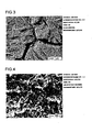
- FIG. 3 is an electron micrograph in magnification of 10,000 times of the surface of a piece of SUS 304 that had been etched using a 10% sulfuric acid aqueous solution at a temperature of 70°C as the etchant, rinsed with water and dried.
- FIG. 4 is an electron micrograph in magnification of 100,000 times.
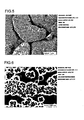
- FIG. 5 is an electron micrograph in magnification of 10,000 times of the surface of a piece of SUS 316 that had been etched using a 10% sulfuric acid aqueous solution as the etchant, rinsed with water and dried.
- FIG. 6 is an electron micrograph in magnification of 100,000 times. As shown in the electron micrographs of FIGS.
- the surface of the piece of SUS 316 has a shape such that amorphous polygons or particulates with a diameter of 20 to 70 nm are stacked on top of one another with things resembling sloped gullies in a lava bed.
- the surface of the piece of SUS 316 can be envisaged to have a ultrafine textured face on a level ranging from a few dozen to a few hundred nanometers in a shape that looks as if large boulders or stones had been stacked up in a sloped mound and these would crumble down to the bottom on the occasion of an earthquake, while it can be seen in FIGS. 3 and 5 that the proportion of the area occupied by this ultrafine textured face in the total area is so high as to be approximately 80 to 100%.
- a halogenated hydroacid such as a hydrochloric acid aqueous solution
- a halogenated hydroacid is suited to etching but when this aqueous solution is brought to a high temperature, there is the risk that part of the acid will volatilize and corrode any surrounding iron structures so that local venting some kind of treatment has to be performed on the exhaust gas.
- the use of a sulfuric acid aqueous solution is preferable in terms of cost.
- a stainless steel substrate that is suited to joining is one in which substantially the entire surface is covered with a ultrafine textured face where amorphous polygons or particulates with a diameter of at least 20 to 70 nm are stacked on top of one another.
- the surface of the stainless steel substrate preferably has an ultrafine textured face in which protrusions with a height, width and length of at least 10 nm rise up at a spacing period of at least 10 nm and has a surface roughness in which the height difference of the bumps made up of the textured face is at least 0.2 ⁇ m at a period of 0.5 to 10 ⁇ m.
- the surface treatment method best suited to the joining referred to in the present invention it is preferable to adopt the procedure in which the products by surface treatment under various conditions are subjected to an injection joining test, those with the highest joint strength are chosen and the surface of stainless steel treated under the same conditions as these is observed with an electron microscope to confirm the presence of the above-mentioned ultrafine textured face and confirm the configuration thereof.
- the injection joining test may be performed after precedent observation with the electron microscope. In either way, injection joining strength should be high for stainless steel having a fine structured surface in which a ultrafine textured face on a level ranging from a few dozen to a few hundred nanometers is reliably formed and present. This has already been confirmed by the inventors with magnesium alloys, aluminum alloys, copper alloys and titanium alloys.
- an undercut structure means that there are places that cannot be seen inside the recesses when the recesses are viewed from above in its vertical plane and, if it were possible to look at these microscopically from the bottom of the recess, overhanging places would be seen. It should be easily understood that undercut structures are necessary for injection joining. In other words, an undercut structure is one in which an interior space of a recess is so formed as to be wider than the opening at the surface.
- the resin composition used in the present invention is a first resin composition whose main component is a polyphenylene sulfide resin, a second resin composition whose main component is a polybutylene terephthalate resin or a third resin composition whose main component is an aromatic polyamide resin.
- the resin component of this first resin composition is a resin composition in which a polyphenylene sulfide resin is the main component and a polyolefin resin is an auxiliary component.
- the resin component of this second resin composition is a resin composition, in which a polybutylene terephthalate resin is the main component and a polyethylene terephthalate resin and/or a polyolefin resin is an auxiliary component.
- the resin component of this third resin composition is a resin composition whose main component is a polyamide resin, in which different kinds of aromatic polyamide resins are mixed, or a resin composition, in which an aromatic polyamide resin is the main component, and whose auxiliary component is an aliphatic polyamide resin.
- the first resin composition preferably contains polyphenylene sulfide resin by 70 to 97 wt% and polyolefin resin by 3 to 30 wt%.
- the second resin composition preferably contains polybutylene terephthalate resin by 70 to 97 wt% and polyethylene terephthalate resin and/or polyolefin resin by 3 to 30 wt%.
- the third resin composition preferably contains aromatic polyamide resin by 70 to 95 wt% and aliphatic polyamide resin by 5 to 30 wt%.
- At least one type of reinforcing fiber selected from among glass fiber, carbon fiber, nylon fiber and aramid fiber, in a total amount of 20 to 60 wt% and at least one type of filler selected from among calcium carbonate, magnesium carbonate, silica, talc, clay and glass powder are further added to the first resin composition, the second resin composition or the third resin composition.
- the remaining 40 to 80 wt% of the first resin composition, second resin composition or third resin composition is resin component. Adding these reinforcing fibers and fillers allows the linear coefficient of expansion of the molded resin to be adjusted to 2 to 3 ⁇ 10 -5 °C -1 and kept as low as possible.
- the PPS resin composition will now be discussed.
- the resin component is composed of PPS by 70 to 97% and polyolefin resin by 3 to 30%, a composite with particularly good joint strength can be obtained.
- the polyolefin resin content is less than 3%, the effect of adding the polyolefin resin on enhancing injection joining strength will not be reliable and the same applies if its content is over 30%.
- the pyrolysis of the polyolefin resin in the injection barrel of the injection molding machine will result in an abnormally large amount of gas being generated, which can hinder even the injection molding itself.
- any PPS can be used as long as it is classified as PPS, while one with a melt viscosity of 100 to 30,000 poise as measured at a temperature of 315°C and a load of 98 N (10 kgf) with a Koka type flow tester mounted with a die 1 mm in diameter and 2 mm long is preferable because it will have better moldability and workability when formed into a resin composition part.
- the PPS may be one substituted with amino groups, carboxyl groups or the like or may be one copolymerized with trichlorobenzene or the like during polymerization.
- the PPS may be of a linear structure or may have a branched structure within it and may have undergone heat treatment in an inert gas, etc.
- the ions, oligomers or other such impurities in the PPS may have been reduced by performing a deionization treatment (acid washing, hot water washing, etc.) or washing treatment with an organic solvent such as acetone before or after heating and curing, while its curing may have been promoted by performing a heat treatment in an oxidative gas upon completion of the polymerization reaction.
- the polyolefin resin is an ethylene resin, propylene resin or other such material normally known as a polyolefin resin and may be a commercially available product.
- maleic anhydride-modified ethylene copolymers, glycidyl methacrylate-modified ethylene copolymers, glycidyl ether-modified ethylene copolymers, ethylene alkyl acrylate copolymers or the like are preferable because a composite with particularly good bondability can be obtained.
- maleic anhydride-modified ethylene copolymers examples include maleic anhydride graft-modified ethylene copolymers, maleic anhydride-ethylene copolymers and ethylene-acrylic acid ester-maleic anhydride ternary copolymers, of which an ethylene-acrylic acid ester-maleic anhydride ternary copolymer is preferable because a particularly excellent composite is obtained.
- a specific example of an ethylene-acrylic acid ester-maleic anhydride ternary copolymer is Bondine (made by Arkema, Kyoto, Japan).
- Examples of glycidyl methacrylate-modified ethylene copolymers include glycidyl methacrylate graft-modified ethylene copolymers and glycidyl methacrylate-ethylene copolymers, of which a glycidyl methacrylate-ethylene copolymer is preferable because a particularly excellent composite is obtained.
- a specific example of a glycidyl methacrylate-ethylene copolymer is Bondfast (made by Sumitomo Chemical, Tokyo, Japan).
- Examples of glycidyl ether-modified ethylene copolymers include glycidyl ether graft-modified ethylene copolymers and glycidyl ether-ethylene copolymers and a specific example of an ethylene alkyl acrylate copolymer is Lotryl (made by Arkema).
- the resin composition part preferably contains polyfunctional isocyanate compound by 0.1 to 6 weight parts and/or epoxy resin by 1 to 25 parts per 100 weight parts of the total resin component including PPS by 70 to 97 wt% and polyolefin resin by3 to 30 wt%, because the joining of the shaped stainless steel and the resin composition part will be better.
- a commercially available non-blocked or blocked polyfunctional isocyanate compound can be used as a polyfunctional isocyanate compound.
- polyfunctional non-blocked isocyanate compounds examples include 4,4'-diphenylmethane diisocyanate, 4,4'-diphenylpropane diisocyanate, toluene diisocyanate, phenylene diisocyanate and bis(4-isocyanate phenyl)sulfone.
- a polyfunctional blocked isocyanate compound has two or more isocyanate groups per molecule, while these isocyanate groups reacted with a volatile active hydrogen compound, making the material inert at normal temperature.
- polyfunctional blocked isocyanate compound there is no particular restriction on the type of polyfunctional blocked isocyanate compound but generally it will have a structure in which the isocyanate groups are masked by a blocking agent such as an alcohol, a phenol, ⁇ -caprolactam, an oxime or an active methylene compound.
- a blocking agent such as an alcohol, a phenol, ⁇ -caprolactam, an oxime or an active methylene compound.
- the epoxy resin can be any commonly known type such as a bisphenol A type or a cresol novolac type.
- An example of a bisphenol A type epoxy resin is Epikote (made by Japan Epoxy Resin, Tokyo, Japan), while an example of a cresol novolac type epoxy resin is Epiclon (made by Dainippon Ink & Chemicals, Tokyo, Japan).
- the resin composition will include not just the above-mentioned filler but 3 to 30% PET and/or polyolefin resin and 70 to 97% PBT.
- Injection joining strength is superior with a PBT resin composition in which PBT is the main component and PET and/or a polyolefin resin is an auxiliary component.
- the same polyolefin resins as those listed for the PPS resin composition can be used.
- Joint strength will be highest when the PET and/or polyolefin resin accounts for 5 to 20%, while the joint will still not be so weak at 3 to 5% or at 20 to 30%.
- the amount is more than 30%, the effect on injection joining strength will be diminished and, if the PET component is over 25%, an ester interchange reaction with PBT will be more likely to proceed at the high temperatures in the injection molding machine, so there is the risk that the strength of the resin itself will be lowered. Also, if the polyolefin resin component is over 30%, more gas will be generated and moldability will tend to be worsened.
- the aromatic polyamide used in the third resin composition will now be described in specific terms.
- the aromatic polyamide referred to here can be a polyamide resin synthesized from a phthalic acid and an aliphatic diamine, such as a polyamide resin synthesized from terephthalic acid and hexamethylenediamine (hereinafter referred to as "nylon 6T”) or a polyamide resin synthesized from isophthalic acid and hexamethylenediamine (hereinafter referred to as "nylon 6I").
- One of the third resin compositions that are favorable for use in the present invention is one in which a mixture of different kinds of aromatic polyamide resins is the main component, a typical example of which is a mixture of the above-mentioned nylon 6T and nylon 6I.
- the main component preferably accounts for 70 to 90%.
- Another of the third resin compositions that are favorable for use in the present invention is one in which an aromatic polyamide resin accounts for 75 to 95% of the resin component and an aliphatic polyamide resin accounts for 5 to 25%. In any case, if the amounts are outside the above ranges, the result will be drop in injection joining strength. It is the theory by Ando, one of the inventors that the crystallization rate during quenching is probably increasing (in other words, it is surmised that "it may be approaching to the normal crystallization rate").
- the resin composition that is used is not limited to the first resin composition, second resin composition or third resin composition and at least one type of reinforcing fiber selected from among glass fiber, carbon fiber, nylon fiber and aramid fiber in a combined amount of 20 to 60 wt% and at least one type of filler selected from among calcium carbonate, magnesium carbonate, silica, talc, clay and glass powder are preferably contained in addition to the above compositions.
- the reason is simple and is that adding these fillers in addition to the resin component lowers the linear coefficient of expansion of the resin composition to about 2 to 3 ⁇ 10 -5 °C -1 .
- a magnesium alloy has a linear coefficient of expansion of about 2.5 ⁇ 10 -5 °C -1 , which is the maximum in metal alloys, and stainless steel has a linear coefficient of expansion of about 1.0 to 1.1 ⁇ 10 -5 °C -1 .
- the linear coefficient of expansion of the resin composition will never reach the level of stainless steel no matter what is done but, for the resin component alone with no filler contained, the linear coefficient of expansion is close to 10 ⁇ 10 -5 °C -1 , which is extremely high, so slight changes in the environment temperature cause internal stress to build up at the joint face and over an extended period of time this can lead to failure.
- One way to prevent such impediments or accidents from happening is to modify the design so that the thickness or toughness of both materials is not strengthened. For example, if one of the materials is made thinner, the internal strain produced by the difference in linear coefficient of expansion will be decreased by expansion or contraction of the thinner material (the weaker material). Methods such as dividing the joint face are also effective in dispersing the force produced by internal strain to other areas. In any case, it will be necessary to check whether or not there is a tendency of the joint strength to be lowered by subjecting the resulting integrated product to a temperature impact test.
- a metal part that has undergone the above-mentioned chemical etching, surface hardening treatment and so forth is inserted into a metallic mold for injection molding, the mold is closed, the above-mentioned resin composition is injected and solidified, after which the mold is opened and the product is removed, thus a composite being manufactured.
- This method for manufacturing a composite is extremely simple and affords good productivity and is, therefore, suited to mass production.
- the injection conditions will be described in brief.
- the temperature of the metallic mold is preferably on the high side since solidification will be too fast if the temperature is too low, even though the resin being used crystallizes more slowly than ordinary resins. Because of this, as well as experimental results, 100°C or higher is preferable and 120°C or higher is even better. If the temperature is too high, on the other hand, the injection molding cycle will end up taking longer, so there is a limit from the standpoint of production efficiency. The inventors think that 120 to 150°C is probably a favorable temperature of the mold.
- the other conditions, namely, injection temperature, injection pressure and injection rate are not much different from those of ordinary injection molding but, if pressed to say, the injection rate and injection pressure are better on the high side. This will probably be understood from the explanation of theory given above.
- FIG. 1 is a cross sectional view of a metallic mold for injection molding 10, schematically illustrating the process of manufacturing a composite of a metal and a resin (a stainless steel piece and a resin composition).
- FIG. 2 is an exterior view schematically illustrating a composite 7 of a metal and a resin (a stainless steel piece and a resin composition).
- the metallic mold for injection molding 10 shown in FIG. 1 and the composite 7 shown in FIG. 2 are common to all the working examples.
- This mold for injection molding 10 is made up of a movable mold plate 2 and a stationary mold plate 3 and a resin injector comprising a pinpoint gate 5, a runner and so forth is constituted on the stationary mold plate 3 side.
- the formation of the composite 7 is carried out as follows. First, the movable mold plate 2 is opened and a stainless steel piece 1 is inserted into the cavity formed between the movable mold plate 2 and the stationary mold plate 3. After this insertion, the movable mold plate 2 is closed, resulting in the state before injection. A molten resin composition is then injected through the pinpoint gate 5 into the cavity in which the stainless steel was inserted. Upon being injected, the resin composition 4 is mated with the stainless steel and fills the cavity that is not occupied by the stainless steel, which gives the integrated composite 7 made up of metal and resin.
- the composite 7 has a joining face 6 between the stainless steel piece 1 and the resin composition 4 and the surface area of this joining face 6 is 5 mm ⁇ 10 mm. Specifically, the surface area of the joining face 6 is 0.5 cm 2 . In the following working examples, strength is obtained using the same basis for the surface area of the joining face. Strength is obtained under the same conditions in the comparative examples given below and comparison is made, as well.
- Melt viscosity was measured with a Koka-type flow tester (CFT-500, made by Shimadzu, Kyoto, Japan) equipped with die having a diameter of 1 mm and a length of 2 mm, at a measurement temperature of 315°C and a load of 98 N (10 kgf).
- CFT-500 Koka-type flow tester
- This photoelectron analyzer was an Axis-Nova (product name, made by Kratos Analytical: England and Shimadzu: Japan), which is a model that allows a surface only a few microns in diameter to be observed to a depth of a few nanometers.
- Electron microscopes were mainly used to observe the substrate surface. These electron microscopes were scanning electron microscopes (SEM): S-4800 (product name, made by Hitachi, Tokyo, Japan) and a JSM-6700F (product name, made by JEOL, Tokyo, Japan), where observations were made at 1 to 2 kV.
- SEM scanning electron microscopes
- This microscope was used mainly to observe the substrate surface.
- This microscope is a scanning probe microscope in which a probe with a pointed tip is used so as to move scanning on the surface of the substance and the surface condition is enlarged for observation.
- This scanning probe microscope was an SPM-9600 (product name; made by Shimadzu, Kyoto, Japan).
- Tensile stress was measured by pulling the composite 7 in a tensile tester to impart shearing force and the breaking force at break was termed the shear stress.
- This tensile tester was a Model 1323 (product name; made by Aikoh Engineering, Tokyo, Japan) and the shear was measured at a pulling rate of 10 mm/minute.
- the temperature of the system was raised to 225°C over 2 hours, the system was polymerized for 2 hours at 225°C, then the temperature was raised to 250°C over 30 minutes and polymerization was conducted for another 3 hours at 250°C.
- the system was cooled to room temperature and the polymer was separated in a centrifuge. The solids of the polymer obtained by this separation were repeatedly washed with warm water and dried over night at 100°C, which gave PPS with a melt viscosity of 280 poise (hereinafter referred to as PPS (1)).
- This PPS (1) was cured for 3 hours at 250°C under a nitrogen atmosphere to obtain PPS (hereinafter referred to as PPS (2)).
- the melt viscosity of the resulting PPS (2) was 400 poise.
- 6.0 kg of the resulting PPS (2), 1.5 kg of ethylene-acrylic ester-maleic anhydride ternary copolymer (Bondine TX8030, made by Arkema) and 0.5 kg of epoxy resin (Epicote 1004, made by Japan Epoxy Resin) were uniformly mixed preliminarily in a tumbler.
- glass fiber with an average fiber diameter of 9 ⁇ m and a fiber length of 3 mm was supplied by side feeder so that the added amount would be 20 wt% while being melt-kneaded in a biaxial extruder (TEM-35B, made by Toshiba Machine, Shizuoka, Japan) at a cylinder temperature of 300°C, which gave a pelletized PPS composition (1).
- the resulting PPS composition (1) was dried for 5 hours at 175°C.
- the PPS (1) obtained in Preparation Example 1 was cured for 3 hours at 250°C under an oxygen atmosphere, which gave PPS (hereinafter referred to as PPS (3)).
- the resulting PPS (3) had a melt viscosity of 1800 poise. 5.98 kg of the resulting PPS (3) and 0.02 kg of polyethylene (Nipolon Hard 8300A, made by Tosoh, Tokyo, Japan) were uniformly mixed preliminarily in a tumbler.
- glass fiber with an average fiber diameter of 9 ⁇ m and a fiber length of 3 mm was supplied by side feeder so that the added amount would be 40 wt% while being melt-kneaded in a biaxial extruder (TEM-35B) at a cylinder temperature of 300°C, which gave a pelletized PPS composition (2).
- the resulting PPS composition (2) was dried for 5 hours at 175°C.
- PBT resin Toraycon 1100S, made by Toray
- PET resin TR-4550BH, made by Teijin Kasei, Tokyo, Japan
- glass fiber with an average fiber diameter of 9 ⁇ m and a fiber length of 3 mm was supplied by side feeder so that the added amount would be 30 wt% while being melt-kneaded in a biaxial extruder (TEM-35B) at a cylinder temperature of 270°C, which gave a pelletized PBT resin composition. This was dried for 3 hours at 140°C to obtain a PBT composition (1).
- glass fiber with an average fiber diameter of 9 ⁇ m and a fiber length of 3 mm (RES03-TP91, made by Nippon Sheet Glass) was supplied by side feeder so that the added amount would be 30 wt% while being melt-kneaded in a biaxial extruder (TEM-35B, made by Toshiba Machine) at a cylinder temperature of 270°C, which gave a pelletized PBT composition (2).
- the resulting PBT composition (2) was dried for 5 hours at 150°C.
- glass fiber with an average fiber diameter of 9 ⁇ m and a fiber length of 3 mm (RES03-TP91, made by Nippon Sheet Glass) was supplied by side feeder so that the added amount would be 30 wt% while being melt-kneaded in a biaxial extruder (TEM-35B, made by Toshiba Machine) at a cylinder temperature of 270°C, which gave a pelletized PBT composition (3).
- the resulting PBT composition (3) was dried for 5 hours at 150°C.
- SUS 304 sheeting with a thickness of 1.0 mm was purchased and cut into numerous rectangular pieces measuring 18 mm ⁇ 45 mm to obtain stainless steel pieces as metal pieces 1. A hole was formed to pass through the end of each steel piece, copper wire coated with polyvinyl chloride was passed through the holes of a dozen or so pieces and the copper wire was bent so that the stainless steel pieces would not overlap each other, thus allowing all pieces to be hung up at the same time.
- An aqueous solution containing aluminum alloy degreaser (NE-6, made by Meltex (Tokyo, Japan)) by 7.5% was adjusted to 60°C and made ready in a tank, while the above-mentioned stainless steel pieces were immersed for 5 minutes and thoroughly rinsed with tap water (Ota City, Gunma, Japan).
- an aqueous solution containing sulfuric acid (98% concentration) by 10% and adjusted to 70°C was made ready in another tank and the above-mentioned metal pieces were immersed for 6 minutes and then thoroughly rinsed with deionized water. They were then dried for 15 minutes in a warm air dryer set to 90°C. The surface was dark brown in color.
- the copper wire was taken out of the stainless steel pieces placed on a clean aluminum foil and the pieces were wrapped up together, then put in a plastic bag, sealed and stored. In this work, no fingers touched the faces to be joined (the end portion on the opposite side from where each hole was formed).
- FIGS. 3 and 4 Two days later, one of the pieces was cut and observed with an electron microscope and a scanning probe microscope.
- the results of observation with the electron microscope in magnification of 10,000 times and 100,000 times are shown in FIGS. 3 and 4 respectively.
- the surface looked can be seen in detail in FIG. 4 and the appearance is such that amorphous polygons or particulates with a diameter of 20 to 70 nm are stacked on top of one another with the surface covered with the above-mentioned ultrafine textured face that looks like gullies. It can be seen in FIG. 3 that this ultrafine textured face extends over the entire surface.
- Observation with the scanning probe microscope revealed a rough surface covered with a roughness of 0.5 to 3 ⁇ m. With XPS, large amounts of oxygen, iron, nickel and chromium were detected and small amounts of carbon and sulfur were also found. The surface layer was therefore considered to be the same as an ordinary oxidized film on stainless steel.
- SUS 304 sheeting was treated part way in exactly the same manner as in Working Example 1. That is, it was degreased and rinsed with water, etched with a sulfuric acid aqueous solution and rinsed with water. A nitric acid aqueous solution with a concentration of 3% was then made ready, adjusted to 40°C, the above-mentioned metal pieces were immersed in this for 3 minutes and thoroughly rinsed with deionized water. They were then dried for 15 minutes in a warm air dryer set at 90°C. After this, the PPS composition (1) was used to perform injection joining and the resulting composites were annealed, all in exactly the same manner as in Working Example 1. A tensile test conducted one day after the annealing revealed the average shear breaking strength to be 28.3 MPa.
- SUS 316 sheeting with a thickness of 1.0 mm was purchased and cut into numerous rectangular pieces measuring 18 mm ⁇ 45 mm to obtain stainless steel pieces as metal pieces 1.
- An aqueous solution containing aluminum alloy degreaser (NE-6, made by Meltex) by 7.5% was adjusted to 60°C and made ready in a tank and the above-mentioned stainless steel pieces were immersed for 5 minutes and thoroughly rinsed with tap water (Ota City, Gunma, Japan).
- an aqueous solution containing 98% sulfuric acid in an amount of 10% and adjusted to 70°C was made ready in another tank.
- the above-mentioned steel pieces were immersed for 3 minutes and then thoroughly rinsed with deionized water. They were then dried for 15 minutes in a warm air dryer set to 90°C. The surface was pale dark brown in color.
- the copper wire was taken out of the stainless steel pieces placed on a clean aluminum foil and the pieces were wrapped up together, then put in a plastic bag, sealed and stored. In this work, no fingers touched the faces to be joined (the end portion on the opposite side from where each hole was formed).
- FIGS. 5 and 6 Two days later, one of the pieces was cut and observed with an electron microscope and a scanning probe microscope. The results of observation with the electron microscope in magnitude of 10,000 times and 100,000 times are shown in FIGS. 5 and 6 respectively. How the surface looked can be seen in detail in FIG. 6 , and the appearance is such that amorphous polygons or particulates with a diameter of 20 to 50 nm are stacked on top of one another, with the surface covered with the above-mentioned ultrafine textured face that looks like gullies. It can be seen in FIG. 5 that this fine textured face extends over 80 to 90% of the surface.
- SUS 301 sheeting with a thickness of 1.0 mm was purchased and cut into numerous rectangular pieces measuring 18 mm ⁇ 45 mm to obtain stainless steel pieces as metal pieces 1.
- aqueous solution containing aluminum alloy degreaser (NE-6, made by Meltex, Tokyo, Japan) by 7.5% was adjusted to 60°C and made ready in a tank and the above-mentioned stainless steel pieces were immersed for 5 minutes and thoroughly rinsed with tap water (Ota City, Gunma, Japan).
- an aqueous solution containing caustic soda by 1.5% and adjusted to 40°C was made ready in another tank and the above-mentioned metal pieces were immersed for 1 minute and then thoroughly rinsed with water.
- an aqueous solution adjusted to 65°C and containing sulfuric acid (98% concentration) by 5% and ammonium monohydrodifluoride by 1% was made ready in another tank and the above-mentioned metal pieces were immersed in this for 1 minute and then thoroughly rinsed with deionized water. They were then immersed for 3 minutes in an aqueous solution containing nitric acid by 3% and adjusted to 40°C and then thoroughly rinsed with deionized water.
- SUS 430 sheeting with a thickness of 1.0 mm was purchased and cut into numerous rectangular pieces measuring 18 mm ⁇ 45 mm to obtain stainless steel pieces as metal pieces 1.
- aqueous solution containing aluminum alloy degreaser (NE-6, made by Meltex, Tokyo, Japan) by 7.5% was adjusted to 60°C and made ready in a tank and the above-mentioned stainless steel pieces were immersed for 5 minutes and thoroughly rinsed with tap water (Ota City, Gunma, Japan).
- an aqueous solution containing caustic soda by 1.5% and adjusted to 40°C was made ready in another tank and the above-mentioned metal pieces were immersed for 1 minute and then thoroughly rinsed with water.
- an aqueous solution adjusted to 65°C and containing sulfuric acid (98% concentration) by 10% and ammonium monohydrodifluoride by 1% was made ready in another tank and the above-mentioned metal pieces were immersed in this for 3 minute and then thoroughly rinsed with deionized water. They were then immersed for 3 minutes in an aqueous solution containing nitric acid by 3% and adjusted to 40°C and then thoroughly rinsed with deionized water.
- SUS 403 sheeting with a thickness of 1.0 mm was purchased and cut into numerous rectangular pieces measuring 18 mm ⁇ 45 mm to obtain stainless steel pieces as metal pieces 1. A hole was formed to pass through the end of each steel piece, copper wire coated with polyvinyl chloride was passed through the holes of a dozen of or so pieces and the copper wire was bent so that the stainless steel pieces would not overlap each other, thus allowing all pieces to be hung up at the same time.
- aqueous solution containing aluminum alloy degreaser (NE-6, made by Meltex, Tokyo, Japan) by 7.5% was adjusted to 60°C and made ready in a tank and the above-mentioned stainless steel pieces were immersed for 5 minutes and thoroughly rinsed with tap water (Ota City, Gunma, Japan).
- an aqueous solution containing caustic soda by 1.5% and adjusted to 40°C was made ready in another tank and the above-mentioned metal pieces were immersed for 1 minute and then thoroughly rinsed with water.
- an aqueous solution adjusted to 65°C and containing sulfuric acid (98% concentration) by 10% and ammonium monohydrodifluoride by 1% was made ready in a separate tank and the above-mentioned metal pieces were immersed in this for 1.5 minute and then thoroughly rinsed with deionized water. They were then immersed for 3 minutes in an aqueous solution containing nitric acid by 3% and adjusted to 40°C and then thoroughly rinsed with deionized water.
- an aqueous solution containing caustic soda by 1.5% and adjusted to 40°C was made ready in another tank and the above-mentioned metal pieces were immersed for 1 minute and then thoroughly rinsed with water.
- an aqueous solution adjusted to 65°C and containing sulfuric acid (98% concentration) by 5% and ammonium monohydrodifluoride by 1% was made ready in another tank and the above-mentioned metal pieces were immersed in this for 8 minute and then thoroughly rinsed with deionized water. They were then immersed for 3 minutes in an aqueous solution containing nitric acid by 3% and adjusted to 40°C and then thoroughly rinsed with deionized water.
- composites were obtained by the same method as in Working Example 1. The composites were annealed for 1 hour at 170°C on the day of the molding and two days later, these composites were subjected to a tensile test, which revealed the shear breaking strength to be an average of 20 MPa.
Landscapes
- Chemical & Material Sciences (AREA)
- Engineering & Computer Science (AREA)
- Mechanical Engineering (AREA)
- General Chemical & Material Sciences (AREA)
- Chemical Kinetics & Catalysis (AREA)
- Materials Engineering (AREA)
- Metallurgy (AREA)
- Organic Chemistry (AREA)
- Manufacturing & Machinery (AREA)
- Injection Moulding Of Plastics Or The Like (AREA)
- ing And Chemical Polishing (AREA)
Applications Claiming Priority (2)
| Application Number | Priority Date | Filing Date | Title |
|---|---|---|---|
| JP2006354636 | 2006-12-28 | ||
| PCT/JP2007/075287 WO2008081933A1 (ja) | 2006-12-28 | 2007-12-28 | 金属と樹脂の複合体とその製造方法 |
Publications (3)
| Publication Number | Publication Date |
|---|---|
| EP2103407A1 EP2103407A1 (en) | 2009-09-23 |
| EP2103407A4 EP2103407A4 (en) | 2012-03-21 |
| EP2103407B1 true EP2103407B1 (en) | 2015-02-11 |
Family
ID=39588613
Family Applications (1)
| Application Number | Title | Priority Date | Filing Date |
|---|---|---|---|
| EP07860490.7A Active EP2103407B1 (en) | 2006-12-28 | 2007-12-28 | Metal/resin composite and process for producing the same |
Country Status (6)
| Country | Link |
|---|---|
| US (2) | US20100028602A1 (ko) |
| EP (1) | EP2103407B1 (ko) |
| JP (1) | JP4927876B2 (ko) |
| KR (1) | KR101115784B1 (ko) |
| CN (1) | CN101568420B (ko) |
| WO (1) | WO2008081933A1 (ko) |
Families Citing this family (66)
| Publication number | Priority date | Publication date | Assignee | Title |
|---|---|---|---|---|
| CN103882430B (zh) | 2007-03-12 | 2017-04-19 | 大成普拉斯株式会社 | 铝合金复合体及其接合方法 |
| ES2405979T3 (es) | 2007-04-06 | 2013-06-04 | Taisei Plas Co., Ltd. | Material compuesto de aleación de cobre y procedimiento para fabricarlo |
| WO2008133030A1 (ja) | 2007-04-13 | 2008-11-06 | Taisei Plas Co., Ltd. | チタン合金複合体とその接合方法 |
| EP2141014A4 (en) * | 2007-04-24 | 2010-07-14 | Taisei Plas Co Ltd | STAINLESS STEEL COMPLEX AND METHOD FOR MANUFACTURING THE SAME |
| US20100189957A1 (en) * | 2007-05-28 | 2010-07-29 | Taisei Plas Co., Ltd. | Steel material composite and manufacturing method thereof |
| WO2009011398A1 (ja) * | 2007-07-17 | 2009-01-22 | Taisei Plas Co., Ltd. | 金属と樹脂の複合体とその製造方法 |
| DE102008040782A1 (de) * | 2008-07-28 | 2010-02-04 | Robert Bosch Gmbh | Bauteilverbund sowie Verfahren zum Herstellen eines Bauteilverbundes |
| WO2010016485A1 (ja) * | 2008-08-06 | 2010-02-11 | 大成プラス株式会社 | 金属合金とポリアミド樹脂組成物の複合体とその製造方法 |
| JP4906004B2 (ja) * | 2009-04-28 | 2012-03-28 | 大成プラス株式会社 | 金属合金と繊維強化プラスチックの複合体の製造方法 |
| JP5501026B2 (ja) * | 2010-02-22 | 2014-05-21 | 日新製鋼株式会社 | ステンレス鋼板と熱可塑性樹脂組成物の成形体とが接合された複合体、およびその製造方法 |
| WO2011152679A2 (ko) * | 2010-06-04 | 2011-12-08 | (주)일광폴리머 | 이종 재질의 일체형 금속 수지 복합 구조물과 그 제조방법 |
| JP5728025B2 (ja) | 2010-11-26 | 2015-06-03 | 大成プラス株式会社 | 金属樹脂複合体とその製造方法 |
| CN102174257B (zh) * | 2011-02-18 | 2013-09-25 | 福建恒劲科博测控技术有限公司 | 一种测力传感弹性复合材料及制作方法 |
| CN102672878A (zh) * | 2011-03-14 | 2012-09-19 | 鸿富锦精密工业(深圳)有限公司 | 不锈钢与树脂的复合体及其制造方法 |
| KR101282626B1 (ko) * | 2011-08-22 | 2013-07-12 | 주식회사 데스코 | 프론트 엔드 모듈 캐리어용 경량화된 강화플라스틱 복합소재 조성물 |
| KR101146602B1 (ko) * | 2011-08-24 | 2012-05-14 | 이희성 | 터치스크린 패널의 커버 윈도우 구조 및 그 제조방법 |
| JP6048145B2 (ja) * | 2011-09-08 | 2016-12-21 | 三菱レイヨン株式会社 | 微細凹凸構造を表面に有する透明フィルム、および、その製造方法 |
| CN103101189A (zh) * | 2011-11-14 | 2013-05-15 | 鸿富锦精密工业(深圳)有限公司 | 复合体的制备方法及该复合体 |
| CN103286908B (zh) | 2012-02-24 | 2015-09-30 | 比亚迪股份有限公司 | 一种金属树脂一体化成型方法和一种金属树脂复合体 |
| CN103286910B (zh) | 2012-02-24 | 2015-09-30 | 比亚迪股份有限公司 | 一种金属树脂一体化成型方法和一种金属树脂复合体 |
| CN103297565B (zh) | 2012-02-24 | 2015-07-22 | 比亚迪股份有限公司 | 一种手机壳体及其制备方法 |
| CN103286995B (zh) | 2012-02-24 | 2015-06-24 | 比亚迪股份有限公司 | 一种铝合金树脂复合体的制备方法及其制备的铝合金树脂复合体 |
| CN103287009B (zh) | 2012-02-24 | 2015-03-25 | 比亚迪股份有限公司 | 一种铝合金树脂复合体的制备方法及其制备的铝合金树脂复合体 |
| CN103286909B (zh) | 2012-02-24 | 2015-09-30 | 比亚迪股份有限公司 | 一种金属树脂一体化成型方法和一种金属树脂复合体 |
| CN103286996B (zh) | 2012-02-24 | 2015-03-25 | 比亚迪股份有限公司 | 一种铝合金树脂复合体的制备方法及其制备的铝合金树脂复合体 |
| WO2013178057A1 (en) | 2012-05-28 | 2013-12-05 | Shenzhen Byd Auto R&D Company Limited | Metal composite and method of preparing the same, metal-resin composite and method of preparing the same |
| CN102837391B (zh) * | 2012-08-22 | 2015-04-22 | 马鞍山市鑫茂铁路器材有限公司 | 一种用于粘接金属的粘接工艺 |
| JP5798535B2 (ja) * | 2012-09-07 | 2015-10-21 | ダイセルポリマー株式会社 | 複合成形体の製造方法 |
| JP2014065220A (ja) * | 2012-09-26 | 2014-04-17 | Brother Ind Ltd | 液体吐出装置の製造方法、ノズルプレートの製造方法、及び、液体吐出装置 |
| US10241235B2 (en) * | 2012-12-25 | 2019-03-26 | Dai Nippon Printing Co., Ltd. | Optical layered object, polarizer obtained using same, and image display device |
| CN103895160B (zh) * | 2012-12-28 | 2016-06-22 | 比亚迪股份有限公司 | 一种不锈钢树脂复合体的制备方法 |
| CN103895161A (zh) * | 2012-12-28 | 2014-07-02 | 比亚迪股份有限公司 | 一种不锈钢树脂复合体的制备方法及其制备的不锈钢树脂复合体 |
| CN103343343A (zh) * | 2013-07-03 | 2013-10-09 | 合肥亿恒机械有限公司 | 一种模具腐蚀溶液 |
| CN105517795B (zh) * | 2013-09-13 | 2017-06-16 | 三井化学株式会社 | 金属/树脂复合结构体 |
| JP6432125B2 (ja) * | 2013-10-24 | 2018-12-05 | 中西金属工業株式会社 | 磁気エンコーダ、及び磁気エンコーダを備えた軸受装置 |
| CN104746066B (zh) | 2013-12-31 | 2017-07-04 | 比亚迪股份有限公司 | 一种金属与塑料的结合材料及其制备方法及制备的结合材料 |
| US10086589B2 (en) * | 2014-03-31 | 2018-10-02 | Nippon Paper Industries Co., Ltd. | Multilayer composite body of metal and polypropylene-based resin composition and method for producing same |
| CN103895156A (zh) * | 2014-04-01 | 2014-07-02 | 东莞劲胜精密组件股份有限公司 | 一种复合体材料及其制备方法 |
| CN104149262B (zh) * | 2014-07-01 | 2017-01-04 | 东莞劲胜精密组件股份有限公司 | 一种液态金属润湿剂及复合体材料的制备方法 |
| WO2016018665A1 (en) * | 2014-07-31 | 2016-02-04 | Uab Research Foundation | Apoe mimetic peptides and higher potency to clear plasma cholesterol |
| KR101493768B1 (ko) * | 2014-09-04 | 2015-02-17 | (주)일광폴리머 | 알루미늄-수지 복합체의 제조 방법 |
| KR101469899B1 (ko) * | 2014-11-04 | 2014-12-08 | (주)일광폴리머 | 금속-수지 복합체의 제조 방법 |
| CA2965605A1 (en) * | 2014-11-18 | 2016-05-26 | Toray Industries, Inc. | Laminate, integrated molding, and method for producing same |
| CN105566909A (zh) * | 2014-12-26 | 2016-05-11 | 比亚迪股份有限公司 | 一种树脂组合物和一种金属-树脂复合体及制备方法和应用以及一种电子产品外壳 |
| CN104608317B (zh) * | 2015-02-03 | 2017-09-26 | 东莞市慧泽凌化工科技有限公司 | 一种金属和树脂的结合体的制备方法及制品 |
| WO2016171128A1 (ja) * | 2015-04-21 | 2016-10-27 | 三井化学株式会社 | 金属/樹脂複合構造体の製造方法および表面粗化鉄鋼部材の製造方法 |
| WO2016199100A1 (en) | 2015-06-10 | 2016-12-15 | Sabic Global Technologies B.V. | Plastic-metal junctions and methods of making the same |
| DE102015217223A1 (de) | 2015-09-09 | 2017-03-09 | Robert Bosch Gmbh | Verfahren zum Ausbilden eines Bauteileverbunds |
| DE102015217232A1 (de) | 2015-09-09 | 2017-03-09 | Robert Bosch Gmbh | Verfahren zum Ausbilden eines Bauteileverbunds |
| WO2017065256A1 (ja) * | 2015-10-14 | 2017-04-20 | 株式会社豊田中央研究所 | 金属樹脂接合部材およびその製造方法 |
| CN106064446B (zh) * | 2016-06-21 | 2018-10-16 | 珠海溥博化工有限公司 | 将不锈钢嵌件注塑成型的方法及不锈钢嵌件 |
| CN106313526B (zh) * | 2016-09-13 | 2018-07-27 | 重庆理工大学 | 一种塑料金属一体化热压成型装置及方法 |
| JP6899639B2 (ja) * | 2016-09-30 | 2021-07-07 | 三井化学株式会社 | 金属/樹脂複合構造体および金属/樹脂複合構造体の製造方法 |
| CN108081729B (zh) * | 2016-11-23 | 2019-10-11 | 比亚迪股份有限公司 | 一种金属纤维复合板及其制备方法 |
| CN106965375A (zh) * | 2017-03-20 | 2017-07-21 | 歌尔股份有限公司 | 一种不锈钢和塑料的结合件及其加工方法 |
| CN106965374A (zh) * | 2017-03-20 | 2017-07-21 | 歌尔股份有限公司 | 一种不锈钢和塑料的结合件及其加工方法 |
| WO2019082983A1 (ja) | 2017-10-27 | 2019-05-02 | 三井化学株式会社 | 金属/樹脂複合構造体および金属/樹脂複合構造体の製造方法 |
| KR101940418B1 (ko) * | 2017-10-30 | 2019-01-18 | 롯데첨단소재(주) | 폴리아미드 수지 조성물 및 이를 포함하는 성형품 |
| CN207537386U (zh) * | 2017-11-23 | 2018-06-26 | 宁德新能源科技有限公司 | 胶纸 |
| KR102171421B1 (ko) | 2017-12-31 | 2020-10-29 | 롯데첨단소재(주) | 폴리아미드 수지 조성물 및 이를 포함하는 성형품 |
| US11577496B2 (en) | 2017-12-31 | 2023-02-14 | Lotte Chemical Corporation | Polyamide resin composition and molded article comprising the same |
| CN108501473B (zh) * | 2018-03-19 | 2023-07-28 | 顺方管业有限公司 | 一种超高分子量聚乙烯板材贴覆在钢板表面的方法 |
| JP7040988B2 (ja) * | 2018-04-20 | 2022-03-23 | 大成プラス株式会社 | アルミニウム合金と樹脂の複合体及びその製造方法 |
| KR20190135193A (ko) * | 2018-05-28 | 2019-12-06 | 삼성전자주식회사 | 스테인리스 스틸 및 레진의 복합체 및 그 제조 방법 |
| KR20230004935A (ko) | 2018-09-21 | 2023-01-06 | 미쯔이가가꾸가부시끼가이샤 | 금속/수지 복합 구조체, 금속/수지 복합 구조체의 제조 방법 및 냉각 장치 |
| WO2022019339A1 (ja) | 2020-07-22 | 2022-01-27 | 三井化学株式会社 | 金属部材、金属樹脂複合体、及び金属部材の製造方法 |
Family Cites Families (13)
| Publication number | Priority date | Publication date | Assignee | Title |
|---|---|---|---|---|
| US5625002A (en) * | 1988-06-02 | 1997-04-29 | Toray Industries, Inc. | Polyphenylene sulfide composition and shaped articles made therefrom |
| JP2849251B2 (ja) * | 1991-12-13 | 1999-01-20 | 川崎製鉄株式会社 | 防眩性と耐食性を兼ね備えた外装用ステンレス鋼板の製造方法 |
| US5275696A (en) * | 1993-05-03 | 1994-01-04 | The United States Of America As Represented By The Secretary Of The Navy | Stainless steel surface treatment |
| JP2001011662A (ja) * | 1999-06-25 | 2001-01-16 | Mec Kk | ステンレス鋼用マイクロエッチング剤およびそれを用いる表面粗化法 |
| JP3680206B2 (ja) * | 2000-10-17 | 2005-08-10 | 古河スカイ株式会社 | 被覆層の密着性に優れた被覆用アルミニウム合金板 |
| WO2003064150A1 (fr) * | 2001-12-28 | 2003-08-07 | Taisei Plas Co., Ltd. | Materiau composite en alliage d'aluminium et en resine, procede de production correspondant |
| JP4076807B2 (ja) * | 2002-07-17 | 2008-04-16 | 大成プラス株式会社 | アルミニューム合金と樹脂の複合体とその製造方法 |
| US8367210B2 (en) * | 2002-11-08 | 2013-02-05 | Taisei Plas Co., Ltd. | Composite article of aluminum alloy with resin and method for production thereof |
| US7841577B2 (en) * | 2002-12-16 | 2010-11-30 | Corona International Corporation | Composite of aluminum material and synthetic resin molding and process for producing the same |
| JP4112378B2 (ja) * | 2003-01-10 | 2008-07-02 | 大成プラス株式会社 | 金属と熱可塑性樹脂組成物の複合体とその製造方法 |
| EP1690664A4 (en) * | 2003-11-14 | 2009-06-03 | Ogura Clutch Co Ltd | METHOD FOR RESIN COATING, INSERT MOLDING, AND RESIN COATED METAL GEARS |
| JP2005342895A (ja) * | 2004-05-31 | 2005-12-15 | Taisei Plas Co Ltd | 金属と樹脂の複合体とその製造方法 |
| US8445106B2 (en) * | 2005-08-02 | 2013-05-21 | Kobe Steel, Ltd. | Resin-coated metal sheet and resin composition |
-
2007
- 2007-12-28 CN CN200780048269.5A patent/CN101568420B/zh active Active
- 2007-12-28 JP JP2008552184A patent/JP4927876B2/ja active Active
- 2007-12-28 EP EP07860490.7A patent/EP2103407B1/en active Active
- 2007-12-28 KR KR1020097012341A patent/KR101115784B1/ko active IP Right Grant
- 2007-12-28 WO PCT/JP2007/075287 patent/WO2008081933A1/ja active Application Filing
- 2007-12-28 US US12/521,149 patent/US20100028602A1/en not_active Abandoned
-
2014
- 2014-04-10 US US14/250,127 patent/US9545740B2/en active Active
Also Published As
| Publication number | Publication date |
|---|---|
| JP4927876B2 (ja) | 2012-05-09 |
| US20100028602A1 (en) | 2010-02-04 |
| US20140217064A1 (en) | 2014-08-07 |
| CN101568420B (zh) | 2014-06-25 |
| CN101568420A (zh) | 2009-10-28 |
| US9545740B2 (en) | 2017-01-17 |
| JPWO2008081933A1 (ja) | 2010-04-30 |
| KR101115784B1 (ko) | 2012-03-09 |
| KR20090091760A (ko) | 2009-08-28 |
| EP2103407A1 (en) | 2009-09-23 |
| WO2008081933A1 (ja) | 2008-07-10 |
| EP2103407A4 (en) | 2012-03-21 |
Similar Documents
| Publication | Publication Date | Title |
|---|---|---|
| US9545740B2 (en) | Composite of metal and resin and method for manufacturing the same | |
| US9751265B2 (en) | Method for preparing a composite of metal and resin | |
| US8273464B2 (en) | Metal and resin composite and method for manufacturing same | |
| EP2174766B1 (en) | Composite of metal with resin and process for producing the same | |
| EP2103406B1 (en) | Process for production of highly corrosion-resistant composite | |
| JP2009298144A (ja) | 複数金属形状物の接合複合体とその製造方法 | |
| JPWO2009031632A1 (ja) | 金属樹脂複合体の製造方法 | |
| KR101469899B1 (ko) | 금속-수지 복합체의 제조 방법 | |
| JP5166978B2 (ja) | 金属合金と樹脂の複合体の製造方法 | |
| KR101389989B1 (ko) | 이종 재질의 일체형 금속 수지 복합 구조물과 그 제조방법 |
Legal Events
| Date | Code | Title | Description |
|---|---|---|---|
| PUAI | Public reference made under article 153(3) epc to a published international application that has entered the european phase |
Free format text: ORIGINAL CODE: 0009012 |
|
| 17P | Request for examination filed |
Effective date: 20090706 |
|
| AK | Designated contracting states |
Kind code of ref document: A1 Designated state(s): AT BE BG CH CY CZ DE DK EE ES FI FR GB GR HU IE IS IT LI LT LU LV MC MT NL PL PT RO SE SI SK TR |
|
| DAX | Request for extension of the european patent (deleted) | ||
| A4 | Supplementary search report drawn up and despatched |
Effective date: 20120217 |
|
| RIC1 | Information provided on ipc code assigned before grant |
Ipc: B29K 23/00 20060101ALI20120213BHEP Ipc: B29C 65/00 20060101ALI20120213BHEP Ipc: B29C 45/14 20060101AFI20120213BHEP Ipc: B29K 67/00 20060101ALI20120213BHEP Ipc: B29K 81/00 20060101ALI20120213BHEP Ipc: B29K 105/22 20060101ALI20120213BHEP Ipc: C23F 1/00 20060101ALI20120213BHEP Ipc: C23F 1/28 20060101ALI20120213BHEP Ipc: B29K 305/00 20060101ALI20120213BHEP |
|
| 17Q | First examination report despatched |
Effective date: 20140127 |
|
| REG | Reference to a national code |
Ref country code: DE Ref legal event code: R079 Ref document number: 602007040246 Country of ref document: DE Free format text: PREVIOUS MAIN CLASS: B29C0045140000 Ipc: B32B0015080000 |
|
| GRAJ | Information related to disapproval of communication of intention to grant by the applicant or resumption of examination proceedings by the epo deleted |
Free format text: ORIGINAL CODE: EPIDOSDIGR1 |
|
| GRAP | Despatch of communication of intention to grant a patent |
Free format text: ORIGINAL CODE: EPIDOSNIGR1 |
|
| RIC1 | Information provided on ipc code assigned before grant |
Ipc: C23C 22/05 20060101ALI20140721BHEP Ipc: B32B 15/08 20060101AFI20140721BHEP |
|
| GRAP | Despatch of communication of intention to grant a patent |
Free format text: ORIGINAL CODE: EPIDOSNIGR1 |
|
| INTG | Intention to grant announced |
Effective date: 20140903 |
|
| GRAS | Grant fee paid |
Free format text: ORIGINAL CODE: EPIDOSNIGR3 |
|
| GRAA | (expected) grant |
Free format text: ORIGINAL CODE: 0009210 |
|
| AK | Designated contracting states |
Kind code of ref document: B1 Designated state(s): AT BE BG CH CY CZ DE DK EE ES FI FR GB GR HU IE IS IT LI LT LU LV MC MT NL PL PT RO SE SI SK TR |
|
| REG | Reference to a national code |
Ref country code: GB Ref legal event code: FG4D |
|
| REG | Reference to a national code |
Ref country code: CH Ref legal event code: EP |
|
| REG | Reference to a national code |
Ref country code: IE Ref legal event code: FG4D |
|
| REG | Reference to a national code |
Ref country code: AT Ref legal event code: REF Ref document number: 709775 Country of ref document: AT Kind code of ref document: T Effective date: 20150315 |
|
| REG | Reference to a national code |
Ref country code: DE Ref legal event code: R096 Ref document number: 602007040246 Country of ref document: DE Effective date: 20150326 |
|
| REG | Reference to a national code |
Ref country code: NL Ref legal event code: VDEP Effective date: 20150211 |
|
| REG | Reference to a national code |
Ref country code: AT Ref legal event code: MK05 Ref document number: 709775 Country of ref document: AT Kind code of ref document: T Effective date: 20150211 |
|
| REG | Reference to a national code |
Ref country code: LT Ref legal event code: MG4D |
|
| PG25 | Lapsed in a contracting state [announced via postgrant information from national office to epo] |
Ref country code: LT Free format text: LAPSE BECAUSE OF FAILURE TO SUBMIT A TRANSLATION OF THE DESCRIPTION OR TO PAY THE FEE WITHIN THE PRESCRIBED TIME-LIMIT Effective date: 20150211 Ref country code: ES Free format text: LAPSE BECAUSE OF FAILURE TO SUBMIT A TRANSLATION OF THE DESCRIPTION OR TO PAY THE FEE WITHIN THE PRESCRIBED TIME-LIMIT Effective date: 20150211 Ref country code: FI Free format text: LAPSE BECAUSE OF FAILURE TO SUBMIT A TRANSLATION OF THE DESCRIPTION OR TO PAY THE FEE WITHIN THE PRESCRIBED TIME-LIMIT Effective date: 20150211 Ref country code: SE Free format text: LAPSE BECAUSE OF FAILURE TO SUBMIT A TRANSLATION OF THE DESCRIPTION OR TO PAY THE FEE WITHIN THE PRESCRIBED TIME-LIMIT Effective date: 20150211 |
|
| PG25 | Lapsed in a contracting state [announced via postgrant information from national office to epo] |
Ref country code: LV Free format text: LAPSE BECAUSE OF FAILURE TO SUBMIT A TRANSLATION OF THE DESCRIPTION OR TO PAY THE FEE WITHIN THE PRESCRIBED TIME-LIMIT Effective date: 20150211 Ref country code: GR Free format text: LAPSE BECAUSE OF FAILURE TO SUBMIT A TRANSLATION OF THE DESCRIPTION OR TO PAY THE FEE WITHIN THE PRESCRIBED TIME-LIMIT Effective date: 20150512 Ref country code: AT Free format text: LAPSE BECAUSE OF FAILURE TO SUBMIT A TRANSLATION OF THE DESCRIPTION OR TO PAY THE FEE WITHIN THE PRESCRIBED TIME-LIMIT Effective date: 20150211 Ref country code: IS Free format text: LAPSE BECAUSE OF FAILURE TO SUBMIT A TRANSLATION OF THE DESCRIPTION OR TO PAY THE FEE WITHIN THE PRESCRIBED TIME-LIMIT Effective date: 20150611 Ref country code: NL Free format text: LAPSE BECAUSE OF FAILURE TO SUBMIT A TRANSLATION OF THE DESCRIPTION OR TO PAY THE FEE WITHIN THE PRESCRIBED TIME-LIMIT Effective date: 20150211 |
|
| PG25 | Lapsed in a contracting state [announced via postgrant information from national office to epo] |
Ref country code: CZ Free format text: LAPSE BECAUSE OF FAILURE TO SUBMIT A TRANSLATION OF THE DESCRIPTION OR TO PAY THE FEE WITHIN THE PRESCRIBED TIME-LIMIT Effective date: 20150211 Ref country code: DK Free format text: LAPSE BECAUSE OF FAILURE TO SUBMIT A TRANSLATION OF THE DESCRIPTION OR TO PAY THE FEE WITHIN THE PRESCRIBED TIME-LIMIT Effective date: 20150211 Ref country code: EE Free format text: LAPSE BECAUSE OF FAILURE TO SUBMIT A TRANSLATION OF THE DESCRIPTION OR TO PAY THE FEE WITHIN THE PRESCRIBED TIME-LIMIT Effective date: 20150211 Ref country code: SK Free format text: LAPSE BECAUSE OF FAILURE TO SUBMIT A TRANSLATION OF THE DESCRIPTION OR TO PAY THE FEE WITHIN THE PRESCRIBED TIME-LIMIT Effective date: 20150211 Ref country code: RO Free format text: LAPSE BECAUSE OF FAILURE TO SUBMIT A TRANSLATION OF THE DESCRIPTION OR TO PAY THE FEE WITHIN THE PRESCRIBED TIME-LIMIT Effective date: 20150211 |
|
| REG | Reference to a national code |
Ref country code: DE Ref legal event code: R097 Ref document number: 602007040246 Country of ref document: DE |
|
| PG25 | Lapsed in a contracting state [announced via postgrant information from national office to epo] |
Ref country code: PL Free format text: LAPSE BECAUSE OF FAILURE TO SUBMIT A TRANSLATION OF THE DESCRIPTION OR TO PAY THE FEE WITHIN THE PRESCRIBED TIME-LIMIT Effective date: 20150211 |
|
| PLBE | No opposition filed within time limit |
Free format text: ORIGINAL CODE: 0009261 |
|
| REG | Reference to a national code |
Ref country code: FR Ref legal event code: PLFP Year of fee payment: 9 |
|
| STAA | Information on the status of an ep patent application or granted ep patent |
Free format text: STATUS: NO OPPOSITION FILED WITHIN TIME LIMIT |
|
| PG25 | Lapsed in a contracting state [announced via postgrant information from national office to epo] |
Ref country code: IT Free format text: LAPSE BECAUSE OF FAILURE TO SUBMIT A TRANSLATION OF THE DESCRIPTION OR TO PAY THE FEE WITHIN THE PRESCRIBED TIME-LIMIT Effective date: 20150211 |
|
| 26N | No opposition filed |
Effective date: 20151112 |
|
| PG25 | Lapsed in a contracting state [announced via postgrant information from national office to epo] |
Ref country code: SI Free format text: LAPSE BECAUSE OF FAILURE TO SUBMIT A TRANSLATION OF THE DESCRIPTION OR TO PAY THE FEE WITHIN THE PRESCRIBED TIME-LIMIT Effective date: 20150211 |
|
| PG25 | Lapsed in a contracting state [announced via postgrant information from national office to epo] |
Ref country code: BE Free format text: LAPSE BECAUSE OF FAILURE TO SUBMIT A TRANSLATION OF THE DESCRIPTION OR TO PAY THE FEE WITHIN THE PRESCRIBED TIME-LIMIT Effective date: 20150211 |
|
| PG25 | Lapsed in a contracting state [announced via postgrant information from national office to epo] |
Ref country code: MC Free format text: LAPSE BECAUSE OF FAILURE TO SUBMIT A TRANSLATION OF THE DESCRIPTION OR TO PAY THE FEE WITHIN THE PRESCRIBED TIME-LIMIT Effective date: 20150211 Ref country code: LU Free format text: LAPSE BECAUSE OF FAILURE TO SUBMIT A TRANSLATION OF THE DESCRIPTION OR TO PAY THE FEE WITHIN THE PRESCRIBED TIME-LIMIT Effective date: 20151228 |
|
| REG | Reference to a national code |
Ref country code: CH Ref legal event code: PL |
|
| REG | Reference to a national code |
Ref country code: IE Ref legal event code: MM4A |
|
| PG25 | Lapsed in a contracting state [announced via postgrant information from national office to epo] |
Ref country code: IE Free format text: LAPSE BECAUSE OF NON-PAYMENT OF DUE FEES Effective date: 20151228 Ref country code: CH Free format text: LAPSE BECAUSE OF NON-PAYMENT OF DUE FEES Effective date: 20151231 Ref country code: LI Free format text: LAPSE BECAUSE OF NON-PAYMENT OF DUE FEES Effective date: 20151231 |
|
| REG | Reference to a national code |
Ref country code: FR Ref legal event code: PLFP Year of fee payment: 10 |
|
| PG25 | Lapsed in a contracting state [announced via postgrant information from national office to epo] |
Ref country code: HU Free format text: LAPSE BECAUSE OF FAILURE TO SUBMIT A TRANSLATION OF THE DESCRIPTION OR TO PAY THE FEE WITHIN THE PRESCRIBED TIME-LIMIT; INVALID AB INITIO Effective date: 20071228 Ref country code: BG Free format text: LAPSE BECAUSE OF FAILURE TO SUBMIT A TRANSLATION OF THE DESCRIPTION OR TO PAY THE FEE WITHIN THE PRESCRIBED TIME-LIMIT Effective date: 20150211 |
|
| PG25 | Lapsed in a contracting state [announced via postgrant information from national office to epo] |
Ref country code: CY Free format text: LAPSE BECAUSE OF FAILURE TO SUBMIT A TRANSLATION OF THE DESCRIPTION OR TO PAY THE FEE WITHIN THE PRESCRIBED TIME-LIMIT Effective date: 20150211 |
|
| PG25 | Lapsed in a contracting state [announced via postgrant information from national office to epo] |
Ref country code: MT Free format text: LAPSE BECAUSE OF FAILURE TO SUBMIT A TRANSLATION OF THE DESCRIPTION OR TO PAY THE FEE WITHIN THE PRESCRIBED TIME-LIMIT Effective date: 20150211 Ref country code: TR Free format text: LAPSE BECAUSE OF FAILURE TO SUBMIT A TRANSLATION OF THE DESCRIPTION OR TO PAY THE FEE WITHIN THE PRESCRIBED TIME-LIMIT Effective date: 20150211 |
|
| REG | Reference to a national code |
Ref country code: FR Ref legal event code: PLFP Year of fee payment: 11 |
|
| PG25 | Lapsed in a contracting state [announced via postgrant information from national office to epo] |
Ref country code: PT Free format text: LAPSE BECAUSE OF FAILURE TO SUBMIT A TRANSLATION OF THE DESCRIPTION OR TO PAY THE FEE WITHIN THE PRESCRIBED TIME-LIMIT Effective date: 20150211 |
|
| PGFP | Annual fee paid to national office [announced via postgrant information from national office to epo] |
Ref country code: GB Payment date: 20231220 Year of fee payment: 17 |
|
| PGFP | Annual fee paid to national office [announced via postgrant information from national office to epo] |
Ref country code: FR Payment date: 20231219 Year of fee payment: 17 Ref country code: DE Payment date: 20231220 Year of fee payment: 17 |