EP2100708B1 - Moule divisé en deux parties pour le formage de pneus et processus de fabrication de pneu au moyen de ce moule - Google Patents
Moule divisé en deux parties pour le formage de pneus et processus de fabrication de pneu au moyen de ce moule Download PDFInfo
- Publication number
- EP2100708B1 EP2100708B1 EP07744646.6A EP07744646A EP2100708B1 EP 2100708 B1 EP2100708 B1 EP 2100708B1 EP 07744646 A EP07744646 A EP 07744646A EP 2100708 B1 EP2100708 B1 EP 2100708B1
- Authority
- EP
- European Patent Office
- Prior art keywords
- superior
- inferior
- tire
- segments
- containers
- Prior art date
- Legal status (The legal status is an assumption and is not a legal conclusion. Google has not performed a legal analysis and makes no representation as to the accuracy of the status listed.)
- Not-in-force
Links
Images

Classifications
-
- B—PERFORMING OPERATIONS; TRANSPORTING
- B29—WORKING OF PLASTICS; WORKING OF SUBSTANCES IN A PLASTIC STATE IN GENERAL
- B29C—SHAPING OR JOINING OF PLASTICS; SHAPING OF MATERIAL IN A PLASTIC STATE, NOT OTHERWISE PROVIDED FOR; AFTER-TREATMENT OF THE SHAPED PRODUCTS, e.g. REPAIRING
- B29C33/00—Moulds or cores; Details thereof or accessories therefor
- B29C33/02—Moulds or cores; Details thereof or accessories therefor with incorporated heating or cooling means
-
- B—PERFORMING OPERATIONS; TRANSPORTING
- B29—WORKING OF PLASTICS; WORKING OF SUBSTANCES IN A PLASTIC STATE IN GENERAL
- B29D—PRODUCING PARTICULAR ARTICLES FROM PLASTICS OR FROM SUBSTANCES IN A PLASTIC STATE
- B29D30/00—Producing pneumatic or solid tyres or parts thereof
- B29D30/06—Pneumatic tyres or parts thereof (e.g. produced by casting, moulding, compression moulding, injection moulding, centrifugal casting)
- B29D30/0601—Vulcanising tyres; Vulcanising presses for tyres
- B29D30/0606—Vulcanising moulds not integral with vulcanising presses
- B29D30/0629—Vulcanising moulds not integral with vulcanising presses with radially movable sectors
-
- B—PERFORMING OPERATIONS; TRANSPORTING
- B29—WORKING OF PLASTICS; WORKING OF SUBSTANCES IN A PLASTIC STATE IN GENERAL
- B29C—SHAPING OR JOINING OF PLASTICS; SHAPING OF MATERIAL IN A PLASTIC STATE, NOT OTHERWISE PROVIDED FOR; AFTER-TREATMENT OF THE SHAPED PRODUCTS, e.g. REPAIRING
- B29C33/00—Moulds or cores; Details thereof or accessories therefor
- B29C33/44—Moulds or cores; Details thereof or accessories therefor with means for, or specially constructed to facilitate, the removal of articles, e.g. of undercut articles
-
- B—PERFORMING OPERATIONS; TRANSPORTING
- B29—WORKING OF PLASTICS; WORKING OF SUBSTANCES IN A PLASTIC STATE IN GENERAL
- B29C—SHAPING OR JOINING OF PLASTICS; SHAPING OF MATERIAL IN A PLASTIC STATE, NOT OTHERWISE PROVIDED FOR; AFTER-TREATMENT OF THE SHAPED PRODUCTS, e.g. REPAIRING
- B29C35/00—Heating, cooling or curing, e.g. crosslinking or vulcanising; Apparatus therefor
- B29C35/02—Heating or curing, e.g. crosslinking or vulcanizing during moulding, e.g. in a mould
-
- B—PERFORMING OPERATIONS; TRANSPORTING
- B29—WORKING OF PLASTICS; WORKING OF SUBSTANCES IN A PLASTIC STATE IN GENERAL
- B29D—PRODUCING PARTICULAR ARTICLES FROM PLASTICS OR FROM SUBSTANCES IN A PLASTIC STATE
- B29D30/00—Producing pneumatic or solid tyres or parts thereof
- B29D30/06—Pneumatic tyres or parts thereof (e.g. produced by casting, moulding, compression moulding, injection moulding, centrifugal casting)
- B29D30/0601—Vulcanising tyres; Vulcanising presses for tyres
- B29D30/0606—Vulcanising moulds not integral with vulcanising presses
- B29D30/0629—Vulcanising moulds not integral with vulcanising presses with radially movable sectors
- B29D2030/063—Vulcanising moulds not integral with vulcanising presses with radially movable sectors the moulds being split in upper and lower halves
-
- B—PERFORMING OPERATIONS; TRANSPORTING
- B29—WORKING OF PLASTICS; WORKING OF SUBSTANCES IN A PLASTIC STATE IN GENERAL
- B29L—INDEXING SCHEME ASSOCIATED WITH SUBCLASS B29C, RELATING TO PARTICULAR ARTICLES
- B29L2030/00—Pneumatic or solid tyres or parts thereof
Definitions
- the present invention relates to a bisplit mold for tire forming and a process for manufacturing a tire with the bisplit mold for tire forming. More specifically, embodiments of the present invention relate to a bisplit mold for tire forming and a process for manufacturing a tire with the bisplit mold for tire forming, which are capable of solving problems that arise in a curing process, and of thus forming a high-performance tire.
- Examples of conventionally known molds used for curing an unvulcanized tire include: a bisplit mold including two, superior and inferior, pieces separated at the tire equatorial plane; and a sectional mold divided, in the circumferential direction of the tire, into plural pieces that expand and contract with respect to the center of the mold.
- the bisplit mold is advantageous in making its equipment simple and small-sized, but has the following drawbacks. Releasing a tire having an intricate tread pattern, which is now common, from the bisplit mold is accompanied by a large resistant force. In addition, opening the mold with the tire adhering to the inner surface of the mold may result in the improper production of tires. Moreover, the use of bisplit mold may result in such other problems as cracking.
- sectional mold which has plural tread-segment portions divided in the circumferential direction of the tire, can deal with an intricate tread pattern. Nevertheless, the sectional mold requires providing, separately, a complex sliding mechanism, thereby resulting in an increase in the cost for the mold.
- Each of the proposed molds for tire curing has a structure that makes the plural divided segments expand and contract with respect to the center of the mold along with the opening-and-closing motion of vertically bisplit, superior and inferior, split shells.
- the use of elastic force of springs for the opening-and-closing action of the segmented mold results in a complex structure.
- mold clamping forces do not act uniformly on the segments, thereby preventing the stable mold clamping.
- the unstable clamping action causes a problem in that the unvulcanized tire is pinched between the segments, resulting in a defective tire product.
- WO 2006/070412 A1 discloses a method and apparatus for manufacturing pneumatic tires
- US 5 405 568 A discloses a tire mold having an upper mold section and a lower mold section with mold segments mounted for sliding movement radially and axially between molding positions and unloading positions of the tire
- US 4 022 554 A discloses retread molds adapted for manual, semi-automatic or fully automatic operation
- DE 1 160 606 B discloses a vulcanizing mold for pneumatic vehicle tires.
- a bisplit mold for tire forming including slide unit means provided respectively in sliding portions formed between superior segments and a superior vertically bisplit center plate and between inferior segments and an inferior vertically bisplit centre plate, the slide unit means being configured to slide the superior and the inferior segments toward a center axis of a tire.
- JP 2000/127173 A JP 2003/340836 A , JP 2003/136535 A and JP 2002/337146 A .
- an object obtainable with embodiments of the present invention is to provide a bisplit mold for tire forming with the following features.
- the bisplit mold having a simple and small-sized structure, can be used for manufacturing high-performance tires. At mold clamping, the pinching of the unvulcanized tire can be avoided, thereby reducing the problems at the curing, resulting in a higher yielding in production.
- embodiments of the present invention also aim to provide a process for manufacturing a tire by use of the bisplit mold for tire forming.
- a bisplit mold for tire forming including: a pair of superior and inferior containers which are formed by being vertically split into superior and inferior halves at a substantial center in a height direction and which come close to and separate away from each other; ring-shaped container rings which are provided respectively to the containers in the tire circumferential direction; a plurality of segments which are provided to each of the containers, and formed by being divided in the tire circumferential direction, the segments each engaging with the corresponding container ring so as to be slidable on an inclined plane formed in the container ring and; opening-closing means which are provided to the respective containers, and cause the superior and the inferior segments to come close to and separate away from each other, the superior and the inferior segments being attached to the pair of superior and inferior containers with vertically bisplit center plates placed between the pair of superior and inferior containers; a superior side plate and an inferior side plate which are attachably and detachably provided respectively to the pair of superior and inferior containers; and vertically bisplit mold pieces
- guide slots are formed respectively in slide bases embedded in the center plates, inclined pin holders engage slidably with the guide slots, respectively, and swing pins are provided so that one end of each of the swing pins is connected to the corresponding one of the inclined pin holders and the other end of each swing pin is embedded in and fixed to the corresponding one of the segments, thereby the swing pin being aligned on the same line as the extended line of the inclination angle of the corresponding one of the guide pins.
- a process for manufacturing a tire with a bisplit mold for tire forming the bisplit mold including: a pair of superior and inferior containers; container rings which are provided respectively to the containers in the tire circumferential direction; a plurality of segments which are provided to each of the containers, and formed by being divided in the tire circumferential direction, the segments each engaging with the corresponding container ring so as to be slidable on an inclined plane formed in the container ring; opening-closing means which are provided to the respective containers, and cause the superior and the inferior segments to come close to and separate away from each other, the superior and the inferior segments being attached to the pair of superior and inferior containers with vertically bisplit center plates placed between the pair of superior and inferior containers; a superior side plate and an inferior side plate which are attachably and detachably provided respectively to the pair of superior and inferior containers; vertically bisplit mold pieces for tire forming which are provided to each of the containers, and attachably and detachably provided to the inner sides of
- the unvulcanized tire is any one of an unvulcanized tire formed by use of a making drum and an unvulcanized tire manufactured by use of a rigid core.
- the present invention provides a bisplit mold for tire forming with the following configuration.
- the bisplit mold for tire forming includes: a pair of superior and inferior containers which are formed by being vertically split into superior and inferior halves at a substantial center in a height direction and which come close to and separate away from each other; ring-shaped container rings which are provided respectively to the containers in the tire circumferential direction; a plurality of segments which are provided to each of the containers, and formed by being divided in the tire circumferential direction, the segments each engaging with the corresponding container ring so as to be slidable on an inclined plane formed in the container ring and; opening-closing means which are provided to the respective containers, and cause the superior and the inferior segments to come close to and separate away from each other, the superior and the inferior segments being attached to the pair of superior and inferior containers with vertically bisplit center plates placed between the pair of superior and inferior containers; a superior side plate and an inferior side plate which are attachably and detachably provided respectively to the pair of superior and inferior containers; and
- slide unit means are provided respectively in sliding portions formed between the superior segments and a superior one of the vertically bisplit center plates and between the inferior segments and an inferior one of the vertically bisplit center plates, the slide unit means being configured to slide the superior and the inferior segments towards a center axis of the tire, inclined guide pins stick out from the pair of superior and inferior containers to the inner side of the pair of superior and inferior containers, and the guide pins are slidably fitted respectively into guide holes formed in the corresponding segments.
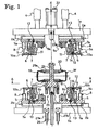
- Fig. 1 is a schematic configuration diagram illustrating a bisplit mold for tire forming of the present invention at the time when the mold is opened.
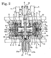
- Fig. 2 is a schematic configuration diagram illustrating the bisplit mold for tire forming at the time when the mold is closed.
- Fig. 3 is a plan view seen as indicated by the arrows A-A of Fig. 1 .
- the bisplit mold for tire forming includes a pair of vertically bisplit superior and inferior containers 3a and 3b. Support plates 2a and 2b provided respectively on the inner-side surfaces of superior and inferior base plates 1a and 1b, which are opposed to each other, are supported by the support place 2a and 2b, respectively.
- the base plates 1a for at least one of the vertically bisplit containers 3 a and 3b (the superior container 3a, in this example) is provided with driving means 4 that are provided so as to stand approximately at the center in the height direction of the bisplit mold.
- the driving means 4 are capable of bringing the bisplit containers 3a and 3b closer to and move away from each other, and hydraulic cylinders, for example, may be used as the driving means 4.
- Each of the containers 3a and 3b includes a container ring 5, plural segments 7, and plural opening-closing means 8.
- the container ring 5 is disposed at the inner side of the corresponding one of the support plates 2a and 2b.
- An inclined plane 6 of a predetermined angle is formed in the container ring 5.
- the plural segments 7, which are formed by being divided in the circumferential direction of the tire (specifically nine segments 7 are formed by being divided in this embodiment, but the number of segments is not limited to a certain number), are slidable on the inclined plate 6 and engage with the container ring 5.
- Examples of the plural opening-closing means 8 are plural hydraulic cylinders (specifically, six opening-closing means 8 are provided in this embodiment, but the number of the opening-closing means 8 is not limited to a certain number).
- the containers 3a and 3b also include a superior side plate 9a and an inferior side plate 9b, respectively.
- Vertically bisplit center plates 10a and 10b are attached to the leading ends of the rods of the corresponding ones of the opening-closing means 8, and arranged so as to be parallel with the splitting plane of the vertically bisplit containers 3a and 3b.
- Members each denoted by reference numeral 8a in Fig. 3 are guide pins.
- Mold pieces 11 for tire forming are attachably and detachably provided to the inner sides of the segments 7.
- Each of the mold pieces 11 for tire forming has a predetermined profile and is formed as a result of dividing a mold into plural sections in the circumferential direction and of splitting each of the resultant sections of the mold into two pieces at the center in the vertical direction.
- plural slide unit means 12 are provided respectively at slide portions where either one of the vertically bisplit center plates 10a and 10b slides on the plural segments 7 formed by being divided in the circumferential direction of the tire.
- the slide unit means 12 can cause pairs of superior and inferior segments 7 to slide towards the center axis X-X of the tire.
- Guide pins 13 are provided on the inner sides of the support plates 2a and 2b and stick out so as to be inclined at a predetermined angle.
- the guide pins 13 are designed to be slidably fitted respectively into guide holes 7a formed in the corresponding segments 7.
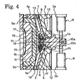
- a slide base 14 is embedded in either one of the center plates 10a and 10b.
- a guide slot 15 is formed in each of the slide bases 14, and an inclined pin holder 16 engages slidably with the corresponding guide slot 15.
- a swing pin 17 that is swingable about a hinge is provided with one of its ends connected to the inclined pin holder 16. The other end of the swing pin 17 is fixed by being embedded in the corresponding segment 7 so as to be aligned on the same line that is drawn by the inclination angle of the guide pin 13 fitted into the guide hole 7a formed in the segment 7.
- the vertically bisplit center plates 10a and 10b are moved with the extending motion of the opening-closing means 8 of the superior and inferior slide unit means 12 so as to be synchronized with the contracting motion of the driving means 4.
- the swing pins 17 provided respectively to the inclined pin holders 16 that slidably engage respectively with the guide slots 15 make the segments 7 that hold their respective mold pieces 11 for tire forming move further away from the center direction X-X of the tire.
- a bladder central mechanism 21 is provided in the central portion of the pair of vertically-bisplit containers 3a and 3b that can be opened and closed.
- the bladder central mechanism 21 is designed to hold either an unvulcanized tire W formed by use of a common making drum or an unvulcanized tire W formed by use of a rigid core.
- the bladder central mechanism 21 is provided with a superior-mold ejector 23a and an inferior-mold ejector 23b.
- the superior-mold ejector 23a and the inferior-mold ejector 23b are disposed so as to be vertically opposed to each other, on the same axis which is the center axis X-X of the tire of the superior base plate 1a and in the inferior base plate 1b.
- An elevator cylinder 22 is provided to install the superior-mold ejector 23a while an unillustrated elevator cylinder is provided to install the inferior-mold ejector 23b.
- the member denoted by reference numeral 19 in the drawings is a bladder while reference numeral 20 denotes a clamp mechanism for the unvulcanized tire W.
- the clamp mechanism 20 includes a center shaft 24, a superior press plate 25a, and an inferior pressing plate 25b.
- the member denoted by reference numeral 26 in the drawings is a center post while reference numerals 27a and 27b are pipes used for introducing a heating medium (for example, air, pressurized steam, or an inert gas such as nitrogen gas) into the unvulcanized tire W.
- a heating medium for example, air, pressurized steam, or an inert gas such as nitrogen gas
- an assembly formed by fitting the superior and the inferior pressing plates 25a and 25b onto the center shaft 24 is incorporated into the containers 3a and 3b.
- the superior pressing plate 25a may be attached to the superior side plate 9a while the inferior pressing plate 25b may be attached to the inferior side plate 9b.
- the containers 3a and 3b may be provided with a vacuum mechanism.
- Fig. 1 shows, the superior container 3a is lifted up by the driving means 4, and the vertically bisplit center plates 10a and 10b are moved by extending their corresponding opening-closing means 8.
- the center post 26 is lifted up by an unillustrated driving apparatus.
- an unvulcanized tire W that has been clamped outside
- an unvulcanized tire W green tire
- an unvulcanized tire W green tire
- an unvulcanized tire W with its upper-side bead ring attached to the elevator cylinder 22 is inserted into the central portion between the center plates 10a and 10b.
- the unvulcanized tire W is clamped with a clamp mechanism 20 and held in that state by making an unillustrated driving means lift up the center post 26.
- the superior container 3a that is suspended from the superior base plate 1a is lowered down by the driving means 4.
- the superior-mold ejector 23a is made, by extending the elevator cylinder 22, to determine the holding position for the upper-surface side of the unvulcanized tire W.
- the superior container 3a and the center post 26 are lowered down by the driving means 4 while being synchronized with each other until the superior and the inferior center plates 10a and 10b come into contact with each other.
- synchronized action is required so that the center of the unvulcanized tire W can lie exactly on the central positions of the center plates 10a and 10b.
- the driving means 4 are lowering the superior container 3a down
- the opening-closing means 8 are brought into action in a coordinated manner. The mold clamping is carried out in this way.
- the container ring 5 attached to the superior support plate 2a and the guide pins 13 attached likewise are lowered down.
- the segments 7, which can slide along the inclined plane 6 of the container ring 5 and which engage with the container ring 5, as well as the slide unit means 12 are lowered down.
- the segments 7 that engage with the guide pins 13 and the container ring 5 at the inclined planes 6 are horizontally moved towards the center axis X-X of the tire so as to contract radially.
- the mold clamping is carried out by contracting radially the segments 7 after the superior and the inferior center plates 10a and 10b come into contact with each other and thus become a vertically closed state. Accordingly, the problem of pinching the unvulcanized tire W between the divided mold pieces 11 for tire forming can be avoided.
- the center post 26 is further lowered down until the side portion of the unvulcanized tire W comes into contact with the inferior side plate 9b. In this state, the pipes 27a and 27b that have come into contact with the bladder central mechanism 21 are connected therewith by clamping.
- vacuum means vacuum suction means
- a heating medium for example, air, pressurized steam, or an inert gas such as nitrogen gas
- the curing of the unvulcanized tire W continues for a predetermined length of time, and then a step of releasing the vulcanized tire from the mold is started.
- the heating medium is discharged from the inside of the cured tire, and the pressure inside the cured tire is lowered down to a predetermined pressure.
- the superior and inferior opening-closing means 8 are extended.
- the extending action of the superior and inferior opening-closing means 8 brings the superior and the inferior center plates 10a and 10b into contact with each other.
- the opening-closing means 8 of the slide unit means 12 extends so that the segments 7 perform the action of leaving the mold.
- Such action of the segments 7, however, does not immediately lead to the radial expansion of the segments 7 in which the guide pins 13 are embedded.
- the inclined pin holders 16 slide, along with the movement of the center plates 10a and 10b, on their respective guide slots 15 that are formed respectively in the slide bases 14.
- the segments 7 to which the mold pieces 11 for the tire forming are attached gradually expand radially.
- the segments 7 are released from the surface of the cured tire.
- the driving means 4 lift the superior container 3a upwards. Then, the superior-mold ejector 23a is lifted up by contracting the elevator cylinders 22, so as to be separated away from the upper-surface side of the formed tire. Subsequently, the driving means 4 lift the superior container 3a further upwards, so that the clamping of the pipes 27a and 27b of the heating means connected to the bladder central mechanism 21 is cancelled.
- the center post 26 which has lifted upward during the time of releasing the cured tire from the mold is stopped at a predetermined position (position for taking out the tire). Then, the camp apparatus of the center post 26 is disengaged, and, after that, the cured tire is taken out at the position for taking out the tire. The taken-out tire is then conveyed to the subsequent process, and thus the work is finished.
- the unvulcanized tire W is placed inside the bisplit containers 3a and 3b, which are in an open-mold state, along the mold pieces 11 for tire forming and along the superior and the inferior side plates 9a and 9b.
- the mold clamping using the superior and the inferior side plates 9a and 9b is carried out by lowering the superior side plate 9a, the segments 7 and the pair of superior and inferior container rings 5 are contracted radially towards the center axis X-X of the tire.
- the opening-closing means 8 disposed between the pair of superior and inferior containers 3a and 3b are driven.
- the mold clamping of the mold pieces 11 for tire forming are carried out using the slide unit means 12, and thus the curing of the tire W is carried out. Accordingly, the curing of a high-performance tire can be done with the bisplit mold, and the uniformity of the tire can be improved.
- the problems at the curing can be reduced by avoiding the pinching of the unvulcanized tire W that might otherwise take place at the mold clamping of the mold pieces 11 for tire forming, so that the yielding can be enhanced.
- the vacuum curing can be done with no lifting force exerted on the tire W, so that a ventless tire with a fine appearance can be manufactured.
- the mold 11 is unlikely to come into close contact with the inner surface of the tire, so that the troubles inside the tire can be reduced.
Claims (4)
- Moule divisé en deux parties pour le formage de pneus comprenant :une paire de récipients supérieur et inférieur (3a, 3b) qui sont formés en étant séparés verticalement en deux, en moitiés supérieure et inférieure à un centre sensible dans le sens de la hauteur et qui se rapprochent et se séparent ;des anneaux de récipient de forme annulaire (5) qui sont prévus respectivement sur les récipients dans la direction circonférentielle du pneu ;une pluralité de segments (7) qui sont prévus sur chacun des récipients, et formés en étant divisés dans la direction circonférentielle du pneu, les segments se mettant chacun en prise avec l'anneau de récipient (5) correspondant pour pouvoir coulisser sur un plan incliné (6) formé dans l'anneau de récipient (5) ;des moyens d'ouverture-fermeture (8) qui sont prévus sur les récipients respectifs, et amènent les segments supérieur et inférieur à se rapprocher et se séparer, les segments supérieur et inférieur étant fixés à la paire de récipients supérieur et inférieur (3a, 3b) avec des plaques centrales verticalement divisées en deux parties (10a, 10b) placées entre la paire de récipients supérieur et inférieur (3a, 3b) ;une plaque latérale supérieure (9a) et une plaque latérale inférieure (9b) qui sont prévues de manière pouvant être attachées et détachées respectivement à la paire de récipients supérieur et inférieur (3a, 3b) ; etdes pièces de moule verticalement divisées en deux parties (11) pour le formage de pneus qui sont prévues sur chacun des récipients, et prévues de manière pouvant être attachées et détachées sur les côtés internes des segments (7), respectivement, dans lequel :des moyens d'unité de coulissement (12) sont prévus respectivement dans les parties coulissantes formées entre les segments supérieurs et une plaque supérieure des plaques centrales verticalement divisées en deux parties (10a) et entre les segments inférieurs et une plaque inférieure des plaques centrales verticalement divisées en deux parties (10b), les moyens d'unité de coulissement étant configurés pour faire coulisser les segments supérieur et inférieur vers l'axe central du pneu (W),des broches de guidage inclinées (13) font saillie de la paire de récipients supérieur et inférieur (3a, 3b) jusqu'au côté interne de la paire de récipients supérieur et inférieur, etles broches de guidage (13) sont montées de manière coulissante respectivement dans les trous de guidage (7a) formées dans les segments (7) correspondants.
- Moule divisé en deux parties pour le formage de pneus selon la revendication 1, dans lequel, dans les moyens d'unité de coulissement (12),
des fentes de guidage (15) sont formées respectivement dans les bases de coulissement (14) enfoncées dans les plaques centrales (10a, 10b),
des supports de broche inclinée (16) se mettent en prise par coulissement avec les fentes de guidage (15), respectivement, et
des broches oscillantes (17) sont prévues de sorte qu'une extrémité de chacune des broches oscillantes (17) est raccordée au support correspondant des supports de broche inclinée (16) et l'autre extrémité de chaque broche oscillante (17) est enfoncée dans et fixée sur le segment correspondant des segments (7) moyennant quoi la broche oscillante (17) est alignée sur la même ligne que la ligne étendue de l'angle d'inclinaison de la broche correspondante des broches de guidage (13). - Procédé pour fabriquer un pneu avec un moule divisé en deux parties pour le formage de pneus, le moule divisé en deux parties comprenant :une paire de récipients supérieur et inférieur (3a, 3b) ;des anneaux de récipient, (5) qui sont prévus respectivement sur les récipients (3a, 3b) dans la direction circonférentielle du pneu ;une pluralité de segments (7) qui sont prévus sur chacun des récipients, et formés en étant divisés dans la direction circonférentielle du pneu, les segments se mettant chacun en prise avec l'anneau de récipient correspondant afin de pouvoir coulisser sur un plan incliné (6) formé dans l'anneau de récipient (5) ;des moyens d'ouverture-fermeture (8) qui sont prévus sur les récipients respectifs, et amènent les segments supérieur et inférieur à se rapprocher et se séparer, les segments supérieur et inférieur étant fixés à la paire de récipients supérieur et inférieur (3a, 3b) avec des plaques centrales verticalement divisées en deux parties (10a, 10b placées entre la paire de récipients supérieur et inférieur (3a, 3b) ;une plaque latérale supérieure et une plaque latérale inférieure qui sont prévues de manière pouvant être attachées et détachées respectivement à la paire de récipients supérieur et inférieur (3a, 3b) ;des pièces de moule verticalement divisées en deux parties (11) pour le formage de pneus qui sont prévues sur chacun des récipients, et prévues de manière pouvant être attachées et détachées sur les côtés internes des segments, respectivement ;des moyens d'unité de coulissement (12) qui sont prévus respectivement dans les parties coulissantes formées entre les segments supérieurs et une plaque supérieure des plaques centrales verticalement divisées en deux parties (10a) et entre les segments inférieurs et une plaque inférieure des plaques centrales verticalement divisées en deux parties (10b), les moyens d'unité de coulissement étant configurés pour faire coulisser les segments supérieur et inférieur vers un axe central du pneu (W), etdes broches de guidage inclinées (13) qui font saillie de la paire de récipients supérieur et inférieur (3a, 3b) jusqu'au côté interne de la paire de récipients supérieur et inférieur (3a, 3b), et qui sont montées de manière coulissante respectivement dans les trous de guidage (7a) formés dans les segments (7) correspondants,le procédé comprenant les étapes consistant à :placer un pneu non vulcanisé (W) le long des pièces de moule (11) pour le formage d'un pneu ainsi que le long d'une plaque latérale supérieure et de la plaque latérale inférieure alors la paire de récipients supérieur et inférieur (3a, 3b) du moule divisé en deux parties pour le formage de pneus est verticalement ouverte ;rétracter radialement, les segments supérieur et inférieur (7) vers l'axe central du pneu non vulcanisé en faisant coulisser les segments supérieur et inférieur sur les plans inclinés (6) respectivement formés dans les anneaux de récipient (5) lorsque la fermeture du moule, à l'aide des plaques latérales supérieure et inférieure, est réalisée en abaissant la plaque latérale supérieure ; etensuite, réaliser un procédé de durcissement du pneu de sorte que la fermeture de moule, des pièces de moule (11) pour le formage de pneus, est réalisée en utilisant les moyens d'unité de coulissement (12) en entraînant les moyens d'ouverture-fermeture (8) disposés entre la paire de récipients supérieur et inférieur (3a, 3b).
- Procédé pour fabriquer un pneu avec un moule divisé en deux parties pour le formage de pneus selon la revendication 3, dans lequel le pneu non vulcanisé est l'un quelconque parmi un pneu non vulcanisé (W) formé à l'aide d'un tambour de fabrication et un pneu non vulcanisé (W) fabriqué à l'aide d'un noyau rigide.
Applications Claiming Priority (2)
| Application Number | Priority Date | Filing Date | Title |
|---|---|---|---|
| JP2007003805A JP4930063B2 (ja) | 2007-01-11 | 2007-01-11 | タイヤ成形用二分割金型 |
| PCT/JP2007/061261 WO2008084564A1 (fr) | 2007-01-11 | 2007-06-04 | Moule divisé en deux parties pour le formage de pneus et processus de fabrication de pneu au moyen de ce moule |
Publications (3)
| Publication Number | Publication Date |
|---|---|
| EP2100708A1 EP2100708A1 (fr) | 2009-09-16 |
| EP2100708A4 EP2100708A4 (fr) | 2013-03-13 |
| EP2100708B1 true EP2100708B1 (fr) | 2014-07-30 |
Family
ID=39608465
Family Applications (1)
| Application Number | Title | Priority Date | Filing Date |
|---|---|---|---|
| EP07744646.6A Not-in-force EP2100708B1 (fr) | 2007-01-11 | 2007-06-04 | Moule divisé en deux parties pour le formage de pneus et processus de fabrication de pneu au moyen de ce moule |
Country Status (6)
| Country | Link |
|---|---|
| US (1) | US8097201B2 (fr) |
| EP (1) | EP2100708B1 (fr) |
| JP (1) | JP4930063B2 (fr) |
| KR (1) | KR101376420B1 (fr) |
| CN (1) | CN101600551B (fr) |
| WO (1) | WO2008084564A1 (fr) |
Families Citing this family (3)
| Publication number | Priority date | Publication date | Assignee | Title |
|---|---|---|---|---|
| JP4814362B2 (ja) * | 2009-08-17 | 2011-11-16 | 住友ゴム工業株式会社 | タイヤ用モールド |
| US9803875B2 (en) | 2011-02-02 | 2017-10-31 | Bsh Home Appliances Corporation | Electric oven with a heating element reflector |
| JP2018187655A (ja) * | 2017-05-09 | 2018-11-29 | 株式会社ブリヂストン | タイヤ用の成形モールドの製造方法 |
Family Cites Families (20)
| Publication number | Priority date | Publication date | Assignee | Title |
|---|---|---|---|---|
| DE1160606B (de) * | 1960-08-20 | 1964-01-02 | Continental Gummi Werke Ag | Vulkanisierform fuer Fahrzeugluftreifen |
| US3778203A (en) * | 1972-04-11 | 1973-12-11 | K Macmillan | Matrix assembly with segmented matrices |
| DE2502185C3 (de) * | 1975-01-21 | 1982-02-04 | Continental Gummi-Werke Ag, 3000 Hannover | Vulkanisierform für Fahrzeugluftreifen |
| US4022554A (en) | 1975-04-16 | 1977-05-10 | Macmillan Mold Company | Retread molds |
| FR2597783B1 (fr) * | 1986-04-25 | 1988-08-26 | Michelin & Cie | Moule rigide pour le moulage et la vulcanisation de pneumatiques |
| US5405568A (en) | 1992-10-26 | 1995-04-11 | The Goodyear Tire & Rubber Company | Two-piece segmented tire mold and method of molding |
| FR2712229A1 (fr) * | 1993-11-12 | 1995-05-19 | Sedepro | Moule pour pneumatique, et procédé de moulage du pneumatique. |
| US5676980A (en) * | 1995-09-29 | 1997-10-14 | Continental General Tire, Inc. | Center split segmented mold for curing pneumatic tires |
| JP4191294B2 (ja) * | 1998-10-22 | 2008-12-03 | 株式会社ブリヂストン | タイヤの加硫成形金型および加硫成形方法 |
| US6318985B1 (en) * | 2000-09-15 | 2001-11-20 | Michelin Recherche Et Technique S.A. | Two-piece segmented mold |
| JP2002337146A (ja) * | 2001-05-15 | 2002-11-27 | Sumitomo Rubber Ind Ltd | タイヤ加硫装置 |
| JP4027638B2 (ja) * | 2001-11-01 | 2007-12-26 | 横浜ゴム株式会社 | タイヤ加硫コンテナーにおけるセグメント摺動装置 |
| JP2003136535A (ja) | 2001-11-01 | 2003-05-14 | Yokohama Rubber Co Ltd:The | タイヤ加硫用コンテナーのストッパー装置 |
| US20040046286A1 (en) * | 2001-08-28 | 2004-03-11 | Akikazu Seko | Method and device for vulcanizing tire |
| US6632393B2 (en) * | 2001-09-06 | 2003-10-14 | Louis T. Fike | Method and apparatus for curing radial tires |
| JP2003340835A (ja) * | 2002-05-27 | 2003-12-02 | Toyo Tire & Rubber Co Ltd | タイヤ成形用金型 |
| JP3626471B2 (ja) | 2002-05-28 | 2005-03-09 | 本田技研工業株式会社 | 樹脂成形用金型構造 |
| US20090008024A1 (en) | 2004-12-28 | 2009-01-08 | Maurizio Marchini | Method and Apparatus for Manufacturing Pneumatic Tyres |
| JP4702130B2 (ja) * | 2006-03-22 | 2011-06-15 | 横浜ゴム株式会社 | タイヤ成形用二分割金型 |
| KR200426690Y1 (ko) | 2006-07-04 | 2006-09-19 | 한국타이어 주식회사 | 자동차용 타이어 가류장치 |
-
2007
- 2007-01-11 JP JP2007003805A patent/JP4930063B2/ja not_active Expired - Fee Related
- 2007-06-04 EP EP07744646.6A patent/EP2100708B1/fr not_active Not-in-force
- 2007-06-04 CN CN2007800496486A patent/CN101600551B/zh not_active Expired - Fee Related
- 2007-06-04 KR KR1020097013109A patent/KR101376420B1/ko not_active IP Right Cessation
- 2007-06-04 US US12/518,840 patent/US8097201B2/en not_active Expired - Fee Related
- 2007-06-04 WO PCT/JP2007/061261 patent/WO2008084564A1/fr active Application Filing
Also Published As
| Publication number | Publication date |
|---|---|
| EP2100708A1 (fr) | 2009-09-16 |
| JP4930063B2 (ja) | 2012-05-09 |
| EP2100708A4 (fr) | 2013-03-13 |
| KR101376420B1 (ko) | 2014-03-20 |
| CN101600551A (zh) | 2009-12-09 |
| CN101600551B (zh) | 2012-06-27 |
| KR20090106488A (ko) | 2009-10-09 |
| US8097201B2 (en) | 2012-01-17 |
| JP2008168510A (ja) | 2008-07-24 |
| US20100000659A1 (en) | 2010-01-07 |
| WO2008084564A1 (fr) | 2008-07-17 |
Similar Documents
| Publication | Publication Date | Title |
|---|---|---|
| EP1997600B1 (fr) | Moule coupe en deux pour moulage de pneu et procede de fabrication de pneu a l' aide du moule | |
| JP3874507B2 (ja) | タイヤ加硫装置 | |
| EP2100708B1 (fr) | Moule divisé en deux parties pour le formage de pneus et processus de fabrication de pneu au moyen de ce moule | |
| JP5424727B2 (ja) | タイヤの製造方法および装置 | |
| GB1565598A (en) | Tyre curing press | |
| JP5270241B2 (ja) | タイヤ加硫機の中心機構、およびタイヤ加硫機のモールド操作方法 | |
| US20100140847A1 (en) | Process and apparatus forr vulcazation and moulding of vehicle tyres | |
| JP3810585B2 (ja) | タイヤ加硫装置 | |
| KR100721415B1 (ko) | 타이어의 가황 방법 및 이 방법을 실시하기 위한 가황기 | |
| JP3865503B2 (ja) | タイヤ加硫装置およびタイヤ加硫装置の金型交換方法並びにタイヤ加硫方法 | |
| JP3865500B2 (ja) | タイヤ加硫装置およびタイヤ加硫装置のモールド交換方法並びにタイヤ加硫方法 | |
| CN111791404A (zh) | 轮胎硫化方法以及轮胎硫化装置 | |
| JP4007714B2 (ja) | タイヤ加硫装置およびその金型交換方法 | |
| JP4191352B2 (ja) | タイヤ金型用コンテナ | |
| JPH02200405A (ja) | タイヤ加硫機のグリーンタイヤ挿入方法及び装置 | |
| JPH10119050A (ja) | タイヤ加硫装置 | |
| JP2000084935A (ja) | タイヤ加硫方法および装置 | |
| US3581345A (en) | Tire curing press bladder assembly | |
| US5466140A (en) | Tire press with improved segmented mold operator | |
| CN113439015B (zh) | 模具容器装置及轮胎硫化机 | |
| US11370188B2 (en) | Process and apparatus for unloading a vulcanised bicycle tyre from a vulcanisation press | |
| JP3953393B2 (ja) | タイヤ加硫方法および装置 | |
| JP2022108821A (ja) | 加硫タイヤの取り出し方法 | |
| JPH08127026A (ja) | タイヤ加硫設備 | |
| JP2001322132A (ja) | タイヤ加硫用コンテナ |
Legal Events
| Date | Code | Title | Description |
|---|---|---|---|
| PUAI | Public reference made under article 153(3) epc to a published international application that has entered the european phase |
Free format text: ORIGINAL CODE: 0009012 |
|
| 17P | Request for examination filed |
Effective date: 20090623 |
|
| AK | Designated contracting states |
Kind code of ref document: A1 Designated state(s): AT BE BG CH CY CZ DE DK EE ES FI FR GB GR HU IE IS IT LI LT LU LV MC MT NL PL PT RO SE SI SK TR |
|
| DAX | Request for extension of the european patent (deleted) | ||
| A4 | Supplementary search report drawn up and despatched |
Effective date: 20130213 |
|
| RIC1 | Information provided on ipc code assigned before grant |
Ipc: B29C 33/44 20060101ALI20130207BHEP Ipc: B29C 33/02 20060101AFI20130207BHEP Ipc: B29C 35/02 20060101ALI20130207BHEP Ipc: B29L 30/00 20060101ALI20130207BHEP |
|
| GRAP | Despatch of communication of intention to grant a patent |
Free format text: ORIGINAL CODE: EPIDOSNIGR1 |
|
| INTG | Intention to grant announced |
Effective date: 20140227 |
|
| GRAS | Grant fee paid |
Free format text: ORIGINAL CODE: EPIDOSNIGR3 |
|
| GRAA | (expected) grant |
Free format text: ORIGINAL CODE: 0009210 |
|
| AK | Designated contracting states |
Kind code of ref document: B1 Designated state(s): AT BE BG CH CY CZ DE DK EE ES FI FR GB GR HU IE IS IT LI LT LU LV MC MT NL PL PT RO SE SI SK TR |
|
| REG | Reference to a national code |
Ref country code: GB Ref legal event code: FG4D |
|
| REG | Reference to a national code |
Ref country code: CH Ref legal event code: EP |
|
| REG | Reference to a national code |
Ref country code: AT Ref legal event code: REF Ref document number: 679730 Country of ref document: AT Kind code of ref document: T Effective date: 20140815 |
|
| REG | Reference to a national code |
Ref country code: IE Ref legal event code: FG4D |
|
| REG | Reference to a national code |
Ref country code: DE Ref legal event code: R096 Ref document number: 602007037887 Country of ref document: DE Effective date: 20140911 |
|
| REG | Reference to a national code |
Ref country code: AT Ref legal event code: MK05 Ref document number: 679730 Country of ref document: AT Kind code of ref document: T Effective date: 20140730 |
|
| REG | Reference to a national code |
Ref country code: NL Ref legal event code: VDEP Effective date: 20140730 |
|
| REG | Reference to a national code |
Ref country code: LT Ref legal event code: MG4D |
|
| PG25 | Lapsed in a contracting state [announced via postgrant information from national office to epo] |
Ref country code: GR Free format text: LAPSE BECAUSE OF FAILURE TO SUBMIT A TRANSLATION OF THE DESCRIPTION OR TO PAY THE FEE WITHIN THE PRESCRIBED TIME-LIMIT Effective date: 20141031 Ref country code: BG Free format text: LAPSE BECAUSE OF FAILURE TO SUBMIT A TRANSLATION OF THE DESCRIPTION OR TO PAY THE FEE WITHIN THE PRESCRIBED TIME-LIMIT Effective date: 20141030 Ref country code: SE Free format text: LAPSE BECAUSE OF FAILURE TO SUBMIT A TRANSLATION OF THE DESCRIPTION OR TO PAY THE FEE WITHIN THE PRESCRIBED TIME-LIMIT Effective date: 20140730 Ref country code: ES Free format text: LAPSE BECAUSE OF FAILURE TO SUBMIT A TRANSLATION OF THE DESCRIPTION OR TO PAY THE FEE WITHIN THE PRESCRIBED TIME-LIMIT Effective date: 20140730 Ref country code: FI Free format text: LAPSE BECAUSE OF FAILURE TO SUBMIT A TRANSLATION OF THE DESCRIPTION OR TO PAY THE FEE WITHIN THE PRESCRIBED TIME-LIMIT Effective date: 20140730 Ref country code: LT Free format text: LAPSE BECAUSE OF FAILURE TO SUBMIT A TRANSLATION OF THE DESCRIPTION OR TO PAY THE FEE WITHIN THE PRESCRIBED TIME-LIMIT Effective date: 20140730 Ref country code: PT Free format text: LAPSE BECAUSE OF FAILURE TO SUBMIT A TRANSLATION OF THE DESCRIPTION OR TO PAY THE FEE WITHIN THE PRESCRIBED TIME-LIMIT Effective date: 20141202 |
|
| PG25 | Lapsed in a contracting state [announced via postgrant information from national office to epo] |
Ref country code: AT Free format text: LAPSE BECAUSE OF FAILURE TO SUBMIT A TRANSLATION OF THE DESCRIPTION OR TO PAY THE FEE WITHIN THE PRESCRIBED TIME-LIMIT Effective date: 20140730 Ref country code: IS Free format text: LAPSE BECAUSE OF FAILURE TO SUBMIT A TRANSLATION OF THE DESCRIPTION OR TO PAY THE FEE WITHIN THE PRESCRIBED TIME-LIMIT Effective date: 20141130 Ref country code: NL Free format text: LAPSE BECAUSE OF FAILURE TO SUBMIT A TRANSLATION OF THE DESCRIPTION OR TO PAY THE FEE WITHIN THE PRESCRIBED TIME-LIMIT Effective date: 20140730 Ref country code: PL Free format text: LAPSE BECAUSE OF FAILURE TO SUBMIT A TRANSLATION OF THE DESCRIPTION OR TO PAY THE FEE WITHIN THE PRESCRIBED TIME-LIMIT Effective date: 20140730 Ref country code: LV Free format text: LAPSE BECAUSE OF FAILURE TO SUBMIT A TRANSLATION OF THE DESCRIPTION OR TO PAY THE FEE WITHIN THE PRESCRIBED TIME-LIMIT Effective date: 20140730 Ref country code: CY Free format text: LAPSE BECAUSE OF FAILURE TO SUBMIT A TRANSLATION OF THE DESCRIPTION OR TO PAY THE FEE WITHIN THE PRESCRIBED TIME-LIMIT Effective date: 20140730 |
|
| PG25 | Lapsed in a contracting state [announced via postgrant information from national office to epo] |
Ref country code: DK Free format text: LAPSE BECAUSE OF FAILURE TO SUBMIT A TRANSLATION OF THE DESCRIPTION OR TO PAY THE FEE WITHIN THE PRESCRIBED TIME-LIMIT Effective date: 20140730 Ref country code: SK Free format text: LAPSE BECAUSE OF FAILURE TO SUBMIT A TRANSLATION OF THE DESCRIPTION OR TO PAY THE FEE WITHIN THE PRESCRIBED TIME-LIMIT Effective date: 20140730 Ref country code: CZ Free format text: LAPSE BECAUSE OF FAILURE TO SUBMIT A TRANSLATION OF THE DESCRIPTION OR TO PAY THE FEE WITHIN THE PRESCRIBED TIME-LIMIT Effective date: 20140730 Ref country code: IT Free format text: LAPSE BECAUSE OF FAILURE TO SUBMIT A TRANSLATION OF THE DESCRIPTION OR TO PAY THE FEE WITHIN THE PRESCRIBED TIME-LIMIT Effective date: 20140730 Ref country code: EE Free format text: LAPSE BECAUSE OF FAILURE TO SUBMIT A TRANSLATION OF THE DESCRIPTION OR TO PAY THE FEE WITHIN THE PRESCRIBED TIME-LIMIT Effective date: 20140730 Ref country code: RO Free format text: LAPSE BECAUSE OF FAILURE TO SUBMIT A TRANSLATION OF THE DESCRIPTION OR TO PAY THE FEE WITHIN THE PRESCRIBED TIME-LIMIT Effective date: 20140730 |
|
| REG | Reference to a national code |
Ref country code: DE Ref legal event code: R097 Ref document number: 602007037887 Country of ref document: DE |
|
| PLBE | No opposition filed within time limit |
Free format text: ORIGINAL CODE: 0009261 |
|
| STAA | Information on the status of an ep patent application or granted ep patent |
Free format text: STATUS: NO OPPOSITION FILED WITHIN TIME LIMIT |
|
| 26N | No opposition filed |
Effective date: 20150504 |
|
| PG25 | Lapsed in a contracting state [announced via postgrant information from national office to epo] |
Ref country code: SI Free format text: LAPSE BECAUSE OF FAILURE TO SUBMIT A TRANSLATION OF THE DESCRIPTION OR TO PAY THE FEE WITHIN THE PRESCRIBED TIME-LIMIT Effective date: 20140730 |
|
| REG | Reference to a national code |
Ref country code: DE Ref legal event code: R119 Ref document number: 602007037887 Country of ref document: DE |
|
| PG25 | Lapsed in a contracting state [announced via postgrant information from national office to epo] |
Ref country code: MC Free format text: LAPSE BECAUSE OF FAILURE TO SUBMIT A TRANSLATION OF THE DESCRIPTION OR TO PAY THE FEE WITHIN THE PRESCRIBED TIME-LIMIT Effective date: 20140730 |
|
| REG | Reference to a national code |
Ref country code: CH Ref legal event code: PL |
|
| GBPC | Gb: european patent ceased through non-payment of renewal fee |
Effective date: 20150604 |
|
| PG25 | Lapsed in a contracting state [announced via postgrant information from national office to epo] |
Ref country code: LU Free format text: LAPSE BECAUSE OF FAILURE TO SUBMIT A TRANSLATION OF THE DESCRIPTION OR TO PAY THE FEE WITHIN THE PRESCRIBED TIME-LIMIT Effective date: 20150604 |
|
| REG | Reference to a national code |
Ref country code: IE Ref legal event code: MM4A |
|
| REG | Reference to a national code |
Ref country code: FR Ref legal event code: ST Effective date: 20160229 |
|
| PG25 | Lapsed in a contracting state [announced via postgrant information from national office to epo] |
Ref country code: IE Free format text: LAPSE BECAUSE OF NON-PAYMENT OF DUE FEES Effective date: 20150604 Ref country code: LI Free format text: LAPSE BECAUSE OF NON-PAYMENT OF DUE FEES Effective date: 20150630 Ref country code: GB Free format text: LAPSE BECAUSE OF NON-PAYMENT OF DUE FEES Effective date: 20150604 Ref country code: CH Free format text: LAPSE BECAUSE OF NON-PAYMENT OF DUE FEES Effective date: 20150630 Ref country code: DE Free format text: LAPSE BECAUSE OF NON-PAYMENT OF DUE FEES Effective date: 20160101 |
|
| PG25 | Lapsed in a contracting state [announced via postgrant information from national office to epo] |
Ref country code: FR Free format text: LAPSE BECAUSE OF NON-PAYMENT OF DUE FEES Effective date: 20150630 |
|
| PG25 | Lapsed in a contracting state [announced via postgrant information from national office to epo] |
Ref country code: BE Free format text: LAPSE BECAUSE OF FAILURE TO SUBMIT A TRANSLATION OF THE DESCRIPTION OR TO PAY THE FEE WITHIN THE PRESCRIBED TIME-LIMIT Effective date: 20140730 |
|
| PG25 | Lapsed in a contracting state [announced via postgrant information from national office to epo] |
Ref country code: MT Free format text: LAPSE BECAUSE OF FAILURE TO SUBMIT A TRANSLATION OF THE DESCRIPTION OR TO PAY THE FEE WITHIN THE PRESCRIBED TIME-LIMIT Effective date: 20140730 |
|
| PG25 | Lapsed in a contracting state [announced via postgrant information from national office to epo] |
Ref country code: HU Free format text: LAPSE BECAUSE OF FAILURE TO SUBMIT A TRANSLATION OF THE DESCRIPTION OR TO PAY THE FEE WITHIN THE PRESCRIBED TIME-LIMIT; INVALID AB INITIO Effective date: 20070604 |
|
| PG25 | Lapsed in a contracting state [announced via postgrant information from national office to epo] |
Ref country code: TR Free format text: LAPSE BECAUSE OF FAILURE TO SUBMIT A TRANSLATION OF THE DESCRIPTION OR TO PAY THE FEE WITHIN THE PRESCRIBED TIME-LIMIT Effective date: 20140730 |