EP2100446B1 - Wandkollisionsvermeidende selbstbalancierende anordnung zur gekippten positionierung einer flachen elektronischen anzeige - Google Patents
Wandkollisionsvermeidende selbstbalancierende anordnung zur gekippten positionierung einer flachen elektronischen anzeige Download PDFInfo
- Publication number
- EP2100446B1 EP2100446B1 EP08712990.4A EP08712990A EP2100446B1 EP 2100446 B1 EP2100446 B1 EP 2100446B1 EP 08712990 A EP08712990 A EP 08712990A EP 2100446 B1 EP2100446 B1 EP 2100446B1
- Authority
- EP
- European Patent Office
- Prior art keywords
- electronic display
- display
- combination
- tilt head
- tilt
- Prior art date
- Legal status (The legal status is an assumption and is not a legal conclusion. Google has not performed a legal analysis and makes no representation as to the accuracy of the status listed.)
- Active
Links
- 230000005484 gravity Effects 0.000 claims description 7
- 230000008878 coupling Effects 0.000 claims 1
- 238000010168 coupling process Methods 0.000 claims 1
- 238000005859 coupling reaction Methods 0.000 claims 1
- 230000000087 stabilizing effect Effects 0.000 claims 1
- 230000000694 effects Effects 0.000 description 4
- 238000012986 modification Methods 0.000 description 2
- 230000004048 modification Effects 0.000 description 2
- 230000003014 reinforcing effect Effects 0.000 description 2
- 230000000712 assembly Effects 0.000 description 1
- 238000000429 assembly Methods 0.000 description 1
- 210000003811 finger Anatomy 0.000 description 1
- 230000004313 glare Effects 0.000 description 1
- 239000004973 liquid crystal related substance Substances 0.000 description 1
- 238000000034 method Methods 0.000 description 1
- 238000010422 painting Methods 0.000 description 1
- 238000010008 shearing Methods 0.000 description 1
- 125000006850 spacer group Chemical group 0.000 description 1
- 210000003813 thumb Anatomy 0.000 description 1
Images


Classifications
-
- F—MECHANICAL ENGINEERING; LIGHTING; HEATING; WEAPONS; BLASTING
- F16—ENGINEERING ELEMENTS AND UNITS; GENERAL MEASURES FOR PRODUCING AND MAINTAINING EFFECTIVE FUNCTIONING OF MACHINES OR INSTALLATIONS; THERMAL INSULATION IN GENERAL
- F16M—FRAMES, CASINGS OR BEDS OF ENGINES, MACHINES OR APPARATUS, NOT SPECIFIC TO ENGINES, MACHINES OR APPARATUS PROVIDED FOR ELSEWHERE; STANDS; SUPPORTS
- F16M13/00—Other supports for positioning apparatus or articles; Means for steadying hand-held apparatus or articles
- F16M13/02—Other supports for positioning apparatus or articles; Means for steadying hand-held apparatus or articles for supporting on, or attaching to, an object, e.g. tree, gate, window-frame, cycle
- F16M13/022—Other supports for positioning apparatus or articles; Means for steadying hand-held apparatus or articles for supporting on, or attaching to, an object, e.g. tree, gate, window-frame, cycle repositionable
-
- F—MECHANICAL ENGINEERING; LIGHTING; HEATING; WEAPONS; BLASTING
- F16—ENGINEERING ELEMENTS AND UNITS; GENERAL MEASURES FOR PRODUCING AND MAINTAINING EFFECTIVE FUNCTIONING OF MACHINES OR INSTALLATIONS; THERMAL INSULATION IN GENERAL
- F16M—FRAMES, CASINGS OR BEDS OF ENGINES, MACHINES OR APPARATUS, NOT SPECIFIC TO ENGINES, MACHINES OR APPARATUS PROVIDED FOR ELSEWHERE; STANDS; SUPPORTS
- F16M11/00—Stands or trestles as supports for apparatus or articles placed thereon Stands for scientific apparatus such as gravitational force meters
- F16M11/02—Heads
- F16M11/04—Means for attachment of apparatus; Means allowing adjustment of the apparatus relatively to the stand
- F16M11/06—Means for attachment of apparatus; Means allowing adjustment of the apparatus relatively to the stand allowing pivoting
- F16M11/10—Means for attachment of apparatus; Means allowing adjustment of the apparatus relatively to the stand allowing pivoting around a horizontal axis
-
- F—MECHANICAL ENGINEERING; LIGHTING; HEATING; WEAPONS; BLASTING
- F16—ENGINEERING ELEMENTS AND UNITS; GENERAL MEASURES FOR PRODUCING AND MAINTAINING EFFECTIVE FUNCTIONING OF MACHINES OR INSTALLATIONS; THERMAL INSULATION IN GENERAL
- F16M—FRAMES, CASINGS OR BEDS OF ENGINES, MACHINES OR APPARATUS, NOT SPECIFIC TO ENGINES, MACHINES OR APPARATUS PROVIDED FOR ELSEWHERE; STANDS; SUPPORTS
- F16M11/00—Stands or trestles as supports for apparatus or articles placed thereon Stands for scientific apparatus such as gravitational force meters
- F16M11/20—Undercarriages with or without wheels
- F16M11/2007—Undercarriages with or without wheels comprising means allowing pivoting adjustment
- F16M11/2014—Undercarriages with or without wheels comprising means allowing pivoting adjustment around a vertical axis
-
- F—MECHANICAL ENGINEERING; LIGHTING; HEATING; WEAPONS; BLASTING
- F16—ENGINEERING ELEMENTS AND UNITS; GENERAL MEASURES FOR PRODUCING AND MAINTAINING EFFECTIVE FUNCTIONING OF MACHINES OR INSTALLATIONS; THERMAL INSULATION IN GENERAL
- F16M—FRAMES, CASINGS OR BEDS OF ENGINES, MACHINES OR APPARATUS, NOT SPECIFIC TO ENGINES, MACHINES OR APPARATUS PROVIDED FOR ELSEWHERE; STANDS; SUPPORTS
- F16M11/00—Stands or trestles as supports for apparatus or articles placed thereon Stands for scientific apparatus such as gravitational force meters
- F16M11/20—Undercarriages with or without wheels
- F16M11/24—Undercarriages with or without wheels changeable in height or length of legs, also for transport only, e.g. by means of tubes screwed into each other
- F16M11/38—Undercarriages with or without wheels changeable in height or length of legs, also for transport only, e.g. by means of tubes screwed into each other by folding, e.g. pivoting or scissors tong mechanisms
-
- F—MECHANICAL ENGINEERING; LIGHTING; HEATING; WEAPONS; BLASTING
- F16—ENGINEERING ELEMENTS AND UNITS; GENERAL MEASURES FOR PRODUCING AND MAINTAINING EFFECTIVE FUNCTIONING OF MACHINES OR INSTALLATIONS; THERMAL INSULATION IN GENERAL
- F16M—FRAMES, CASINGS OR BEDS OF ENGINES, MACHINES OR APPARATUS, NOT SPECIFIC TO ENGINES, MACHINES OR APPARATUS PROVIDED FOR ELSEWHERE; STANDS; SUPPORTS
- F16M13/00—Other supports for positioning apparatus or articles; Means for steadying hand-held apparatus or articles
- F16M13/02—Other supports for positioning apparatus or articles; Means for steadying hand-held apparatus or articles for supporting on, or attaching to, an object, e.g. tree, gate, window-frame, cycle
-
- F—MECHANICAL ENGINEERING; LIGHTING; HEATING; WEAPONS; BLASTING
- F16—ENGINEERING ELEMENTS AND UNITS; GENERAL MEASURES FOR PRODUCING AND MAINTAINING EFFECTIVE FUNCTIONING OF MACHINES OR INSTALLATIONS; THERMAL INSULATION IN GENERAL
- F16M—FRAMES, CASINGS OR BEDS OF ENGINES, MACHINES OR APPARATUS, NOT SPECIFIC TO ENGINES, MACHINES OR APPARATUS PROVIDED FOR ELSEWHERE; STANDS; SUPPORTS
- F16M2200/00—Details of stands or supports
- F16M2200/06—Arms
- F16M2200/061—Scissors arms
-
- H—ELECTRICITY
- H04—ELECTRIC COMMUNICATION TECHNIQUE
- H04N—PICTORIAL COMMUNICATION, e.g. TELEVISION
- H04N5/00—Details of television systems
- H04N5/64—Constructional details of receivers, e.g. cabinets or dust covers
Definitions
- the present invention relates to flat panel display devices, and more specifically to mounting devices for flat panel electronic display devices.
- U.S. Patent Nos. 6,905,101 , 7,028,961 , and 7,152,836 all of which are owned by the owner of the present invention and are hereby fully incorporated herein by reference.
- U.S. Patent No. 6,905,101 relates to a self-balanced adjustable mounting system which allows a display to revolve about a substantially horizontal axis extending proximate a centre of gravity of the display.
- WO2006/044969 relates to a mounting system for a flat panel display, wherein a flat panel display can be immobilised at a plurality of angles relative to a support surface.
- WO2006/133188 also relates to a mounting system for a flat panel display, the mount having articulated aims and being both vertically and horizontally adjustable
- a drawback of these previous mount designs is that the edges of the display may sometimes collide with the wall surface during positioning. These collisions may leave unsightly marks or gouges in the wall surface, or may cause damage to the display itself. Hence, there is still a need for a flat panel display mount that enables selective positioning of the display while alleviating the undesirable effects of wall collisions.
- Device and methods according to the present invention generally include a support structure operably connected to a display interface structure and a tilt head assembly.
- the display interface structure is attached to the electronic display.
- the support structure includes an extendable arm assembly, a pivot column, and a swingstop post.
- the support structure can be used to rotatably position the electronic device about a substantially vertical axis.
- the tilt head assembly includes an attachment member, a positionable plate, and guide structures. The tilt head assembly can be used to rotatably position the electronic display about a substantially horizontal axis.
- a combination of an electronic display and a device for mounting said electronic display to a substantially vertically oriented surface comprising: a display interface structure; a support structure; and a tilt head assembly for tilting the electronic display, characterised in that the tilt head assembly includes an attachment member and first and second guide structures, the attachment member being operably connected to the support structure and the first and second guide structures defining a path of travel of the electronic display about a tilt axis such that a bottom edge of the electronic display remains at substantially a same first distance from the substantially vertically oriented surface while a top edge of the electronic display tilts away from the substantially vertically oriented surface as the electronic display travels about the tilt axis, and such that a centre of gravity of the electronic display translates along a substantially horizontal axis as the electronic display travels about the tilt axis, wherein the electronic display is substantially self-balancing at any point along the path of rotation and the support structure is operably connected to the display interface structure and the attachment member.
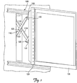
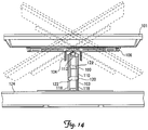
- Mount 100 can be used to mount flat panel display 101 to wall 102.
- mount 100 includes support structure 103, tilt head 104, and display interface structure 106.
- Mount may also include in-wall box 108.
- Support structure 103 generally includes extendable arm assembly 110, support column assembly 112, and swing limit cam 114.
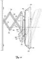
- Extendable arm assembly 110 generally includes wall interface 116 and arms 118, pivotally coupled together at pivots 120. Lateral spacers 122 may be provided at pivots 120 to provide lateral spacing between adjacent arms 118 in order to avoid pinch points and shearing action as extendable arm assembly 110 is extended and retracted. As depicted in Figures 14-15 , extendable arm assembly 110 enables display 101 to be selectively positioned at any desired distance outward from wall surface 124.
- extendable arm assembly 110 may include virtually any desired number of arms 118 so as to enable a desired range of movement outward from wall surface 124.
- support structure 103 may include or consist of any other structure providing support for tilt head 104, such as swing arm arrangements or fixed mounting brackets.
- support structure 103 may be attached directly to wall surface 124, or may be advantageously used with in-wall attachment arrangements such as disclosed for example in the U.S Provisional Application No. 60/883,652 CENTERING IN-WALL MOUNT filed by the owners of the present invention on January 5, 2007, the complete disclosure of which is hereby fully incorporated herein by reference.
- Support column assembly 112 generally includes tubular vertical column 126, upper pivot bushing 128, lower pivot bushing 130 and lift adjuster assembly 132.
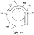
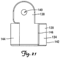
- Upper pivot bushing 128, as depicted in Figs. 19-21 generally includes body portion 134 defining central bore 136.
- Tab 138 extends from body portion 134 and defines pivot aperture 140.
- Body portion 134 is generally cylindrical with front edge 142 having a smaller radius than rear edge 144, defining a pair of shoulders 146, 148.
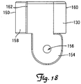
- lower pivot bushing 130 generally includes body portion 150 defining central bore 152.
- Tab 154 extends from body portion 150 and defines pivot aperture 156.
- Body portion 150 is generally cylindrical with front edge 158 having a smaller radius than rear edge 160, defining a pair of shoulders 162, 164.
- Upper and lower pivot bushings 128, 130 are vertically and rotationally slidably disposed on column 126, with column 126 extending through central bores 136, 152, respectively.
- Separate arms 118 of extendable arm assembly 110 are pivotally attached to tabs 138, 154, of each of upper and lower pivot bushings 128, 130, with pivots 166 extending into pivot apertures 140, 156.
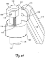
- Lift adjuster assembly 132 as depicted in Figure 26 generally includes body 168, attaching fastener 170, and lift screw 172.
- Body 168 is attached proximate upper end 174 of column 126 with attaching fastener 170.
- Lift screw 172 is threadedly received in body 168 and includes bearing plate 176 at lower end 178.
- Thumb knob 180 may be provided on upper end 182 to enable lift screw 172 to be easily threaded in and out of body 168 with the fingers.
- bearing plate 176 slidably bears on upper surface 184 of upper pivot bushing 128, thereby vertically locating upper pivot bushing 128 on column 126.
- the relative vertical position of upper pivot bushing 128 is selectively adjustable by threading lift screw 172 in or out of body 168, thereby lowering or raising upper pivot bushing 128 relative to column 126.
- upper pivot bushing 128 remains in position while lower pivot bushing 130 slides vertically on column 126.
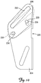
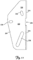
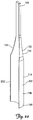
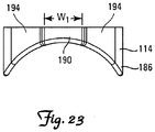
- Swing limit cam 114 generally includes elongate body 186 presenting lower end 188 and upper end 190.
- Lower end 188 has width dimension W that is generally wider than width dimension W 1 of upper end 190.
- Intermediate portion 192 is tapered, presenting upwardly sloping opposing flanks 194.
- Front side 196 is concave, conforming to the radius of front edge 158 of lower pivot bushing 130.
- Swing limit cam 114 is affixed to the inner side 198 of tilt head 104 as depicted in Figure 13 , with front edge 158 of lower pivot bushing 130 in registry with front side 196 as depicted in Figure 25 .
- Column 126 is positioned along concave front side 196 of swing limit cam 114 and is fixed in rotational and vertical position relative thereto. In use, with display 101 positioned proximate wall surface 124 as depicted in Figure 15 , lower pivot bushing 130 is relatively closer to bottom end 200 of column 126.
- lower pivot bushing 130 slides upward on column 126 and upward relative to swing limit cam 114, which is vertically fixed in position on tilt head 104.
- swing limit cam 114 which is vertically fixed in position on tilt head 104.
- swing limit cam 114 may be adjusted on tilt head 104 to alter the relative distance from wall surface 124 at which lower pivot bushing 130 begins to encounter intermediate portion 192 and upper end 190.
- geometry of swing limit cam 114 may be altered as desired to produce desired swing limiting characteristics.
- swing limit cam 114 may be made relatively longer with more gently sloping flanks 194 to enable a more gradual limiting of swing motion relative to distance.
- opposing flanks 194 may a provided with differing slopes so as to enable a greater range of swing motion in one direction relative to the opposing direction.
- Tilt head 104 is generally attached intermediate support structure 103 and display interface structure 106.
- tilt head 104 generally includes inner yoke 204, pitch cams 206, and pitch member 208, as depicted in Figures 8-11 .
- tilt head 104 generally includes body portion 210, a pair of inner pitch arms 212, a pair of outer pitch arms 214, and a display interface assembly 216, as depicted in Figures 27-32 .
- inner yoke 204 generally includes back plane 218 defining laterally oriented opening 220, and having parallel projecting flanges 222, 224.
- Each pitch cam 206 defines a guide structure 232, which may be in the form of an elongate slot, and a pair of apertures 234, 236.
- Pitch cams 206 are secured on the outer surface 238 of each of flanges 222, 224, with aperture 234 in registry with oblong aperture 228 and aperture 236 in registry with oblong aperture 230.
- Travelers extend through each of the registered aperture pairs228, 234 and 230, 236. The travelers are slidable in oblong apertures 228, 230 such that pitch cams 206 are selectively positionable relative to inner yoke 204 as depicted in Figure 10 .
- Pitch member 208 generally includes back plane 239 having parallel projecting flanges 240, 242. Each of flanges 240, 242, define apertures 244, 246, in lateral registry across tilt head 104. Inner yoke 204 and pitch cams 206 are disposed between flanges 240, 242, with apertures 244 in registry with guide structures 232, and apertures 246 in registry with guide structures 226.
- followers 248 extend through apertures 244 and slidably engage in each guide structure 232, and followers 250 extend through apertures 246 and slidably engage in each guide structure 226.
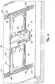
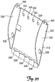
- Display interface structure 106 as depicted in Figure 13 , generally includes vertical uprights 252, 254, horizontal braces 256, 258, central reinforcing plate 260, and gusset plates 262, 264.
- Vertical uprights 252, 254, are secured to back side 266 of display 101 with fasteners 268.
- Horizontal braces 256, 258, are secured to vertical uprights 252, 254, and are coupled with gusset plates 262, 264.
- Central reinforcing plate 260 extends between and is secured to horizontal braces 256, 258.
- Pitch member 208 engages and is secured to horizontal braces 256, 258.
- display 101 is tiltable about a generally horizontal tilt axis by grasping the top edge 270 of the display 101 and pulling outward.
- followers 248 slide in guide structures 232
- followers 250 slide in guide structures 226 to guide and define the tilting path of travel for display 101.
- bottom edge 272 maintains substantially the same distance from wall surface 124.
- tilt head 104 may be oriented so as to define a path of travel about a tilt axis located generally below and forward of display 101, such that center of gravity 274 translates along a substantially horizontal axis 198, and the display 101 is substantially "self-balancing.” That is, display 101 will maintain a desired tilt position without being held by a secondary friction source.
- the position of pitch cams 206 may be adjusted so as to alter the position of the tilt axis for display 101 and also the path along which the center of gravity will translate upon tilting.
- the shape of guide structures 226, 232 may be altered so as to give a desired effect to the tilt motion of display 101.
- guide structures 226, 232 may be substantially straight as depicted, or either or both may be curved, angular, or any other desired shape.
- Guide structures 226, 232 themselves, although depicted as slots, may be any other suitable structure capable of guiding a follower, such as channels, grooves, cam surfaces, and the like.
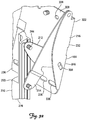
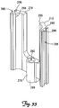
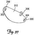
- body portion 210 generally includes yoke portion 276 with a pair of projecting uprights 278, 280.
- Yoke portion 276 defines central bore 282, of which a portion proximate bottom end 284 may be threaded to receive threaded coupler 286.
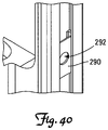
- Each of uprights 278, 280 defines guide track 288 facing laterally outward.
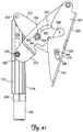
- a slide block 290 is slidably disposed in each guide track 288 as depicted in Figure 40 .
- Slide block 290 defines aperture 292.
- Each upright 278, 280 defines aperture 294 therethrough proximate top end 296.
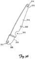
- Outer pitch arm 214 is also elongate, presents opposing ends 308, 310, and defines apertures 312, 314 proximate ends 308, 310, respectively.
- Clearance notch 316 is defined in lateral margin 318 proximate aperture 320.
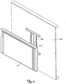
- display 101 may be first disposed in a generally vertical upright position, as depicted in Figure 27 .
- Lower corner 350 is disposed a distance D from upright column 352 of extendable arm assembly 110, upon which yoke portion 276 is received.
- Center of gravity C.G. of display 101 is disposed along generally horizontal axis A-A, which is a distance X above bottom end 284 of yoke portion 276.
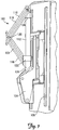
- a user may selectively tilt display 101 forward as depicted in Figure 28 by grasping and pulling top edge 270 of display 101.
- each inner pitch arm 212 pivots about pivots 344, 346, and pivot 344 slides in elongate guide slot 338.
- each outer pitch arm 214 pivots about pivots 346, with each slide block 290 sliding upward in guide tracks 288.
- center of gravity C.G. of display 101 translates substantially along axis A-A, which is maintained at distance X above the bottom end 284 of yoke portion 276, while lower corner 350 remains substantially at the same distance D from upright column 352.
- display 101 to be essentially self-balancing, able to maintain any desired tilt position between the upright position depicted in Figure 27 and the fully tilted position depicted in Figure 28 without the addition of significant additional friction between any of the components of mount 100.
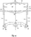
- the lower corner 350 of display 101 maintains an essentially constant distance from wall assembly 354 as display 101 is tilted, thereby eliminating the problem of display 101 striking wall assembly 354, even when mount 100 is fully retracted as depicted in Figure 44 .
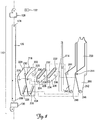
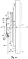
- mount 100 additionally includes friction element 356, which may include a bolt 358 extending through an aperture defined in inner pitch arm 212 and guide slot 360 defined in outer pitch arm 214.
- Friction washer 362 abuts outer surface 364 of outer pitch arm 214 and is held in place with nut 366.
- Notch 368 is defined in each of parallel flanges 330, 332 to clear friction element 356.
- friction can be selectively added if needed to maintain a desired tilt position by tightening nut 366. Conversely, friction can be removed to enable freer positioning of mount 100 by loosening nut 366.
Claims (9)
- Kombination aus einer elektronischen Anzeige und einer Vorrichtung zum Befestigen der elektronischen Anzeige an einer im Wesentlichen vertikal ausgerichteten Fläche, wobei die Vorrichtung Folgendes umfasst:eine Anzeigenschnittstellenstruktur (106),eine Tragstruktur (103) undeine Kippkopfanordnung (104) zum Kippen der elektronischen Anzeige, dadurch gekennzeichnet, dass die Kippkopfanordnung ein Anbringungselement (204, 276) sowie eine erste und eine zweite Führungsstruktur (226, 232, 288, 338) umfasst, wobei das Anbringungselement mit der Tragstruktur (103) wirkverbunden ist und die erste und die zweite Führungsstruktur einen Laufweg der elektronischen Anzeige um eine Kippachse auf eine solche Weise festlegen, dass eine Unterkante der elektronischen Anzeige in einem im Wesentlichen gleichen ersten Abstand von der im Wesentlichen vertikal ausgerichteten Fläche bleibt, während eine Oberkante der elektronischen Anzeige weg von der im Wesentlichen vertikal ausgerichteten Fläche kippt, während die elektronische Anzeige um die Kippachse läuft, und auf eine solche Weise, dass ein Schwerpunkt (274) der elektronischen Anzeige entlang einer im Wesentlichen horizontalen Achse (198) eine translatorische Bewegung ausführt, während die elektronische Anzeige um die Kippachse läuft, wobei die elektronische Anzeige an jedem beliebigen Punkt entlang des Laufwegs im Wesentlichen selbstbalancierend ist und die Tragstruktur (103) mit der Anzeigenschnittstellenstruktur (106) und dem Anbringungselement (204, 276) wirkverbunden ist.
- Kombination nach Anspruch 1, wobei die Oberkante der Vorrichtung um wenigstens ungefähr dreißig Grad drehbar ist.
- Kombination nach einem der Ansprüche 1 bis 2, wobei die erste und die zweite Führungsstruktur (226, 232, 288, 338) der Vorrichtung längliche Schlitze (338, 360) umfassen.
- Kombination nach einem der Ansprüche 1 bis 3, wobei die Kippkopfanordnung (104) der Vorrichtung ferner ein Reibelement (356) zum Stabilisieren der elektronischen Anzeige umfasst.
- Kombination nach einem der vorhergehenden Ansprüche, wobei die Tragstruktur (103) der Vorrichtung ferner auf eine solche Weise angepasst ist, dass die elektronische Anzeigevorrichtung gezielt um eine im Wesentlichen vertikale Schwenkachse verschwenkbar ist.
- Kombination nach einem der vorhergehenden Ansprüche, ferner in der Vorrichtung eine senkrecht ausgerichtete Schwenksäule (126) umfassend, die die Kippkopfanordnung (104) mit der Tragstruktur (103) wirkverkoppelt, wobei die Schwenksäule (126) die im Wesentlichen vertikale Schwenkachse festlegt.
- Kombination nach einem der vorhergehenden Ansprüche, wobei die Tragstruktur (103) der Vorrichtung eine ausfahrbare Armanordnung (110) umfasst, wobei die ausfahrbare Armanordnung ein gezieltes Verschieben der elektronischen Anzeige in einer im Wesentlichen horizontalen Richtung zwischen einer ersten Stellung, in der sich die elektronische Anzeigevorrichtung benachbart zu der im Wesentlichen vertikal ausgerichteten Fläche befindet, und einer zweiten Stellung, in der die elektronische Anzeige von der im Wesentlichen vertikal ausgerichteten Fläche beabstandet ist, ermöglicht.
- Kombination nach Anspruch 6 oder Anspruch 7 bei Abhängigkeit von Anspruch 6, ferner in der Vorrichtung einen Schwingbegrenzungsnocken (114) an dem einen aus der Kippkopfanordnung (104) und der Schwenksäule (126) sowie eine untere Schwenkbuchse (130) an dem anderen aus der Kippkopfanordnung (104) und der Schwenksäule (126) umfassend, wobei der Schwingbegrenzungsnocken (114) und die untere Gelenkbuchse (130) zusammenwirkend angeordnet sind, um ein Verschwenken der elektronischen Anzeigevorrichtung um die im Wesentlichen vertikale Schwenkachse auf einen vorgegebenen Winkelbereich zu begrenzen.
- Kombination nach Anspruch 8, wobei der Schwingbegrenzungsnocken (114) und die untere Schwenkbuchse (130) auf eine solche Weise ausgelegt und angeordnet sind, dass sich der vorgegebene Winkelbereich erhöht, während die elektronische Anzeige weg von der im Wesentlichen vertikal ausgerichteten Fläche mit der ausfahrbaren Armanordnung (110) verschoben wird.
Applications Claiming Priority (3)
| Application Number | Priority Date | Filing Date | Title |
|---|---|---|---|
| US88365607P | 2007-01-05 | 2007-01-05 | |
| US95794107P | 2007-08-24 | 2007-08-24 | |
| PCT/US2008/000117 WO2008085889A1 (en) | 2007-01-05 | 2008-01-04 | Wall-avoiding self-balancing mount for tilt positioning of a flat panel electronic display |
Publications (3)
| Publication Number | Publication Date |
|---|---|
| EP2100446A1 EP2100446A1 (de) | 2009-09-16 |
| EP2100446A4 EP2100446A4 (de) | 2009-12-16 |
| EP2100446B1 true EP2100446B1 (de) | 2018-10-17 |
Family
ID=39608994
Family Applications (1)
| Application Number | Title | Priority Date | Filing Date |
|---|---|---|---|
| EP08712990.4A Active EP2100446B1 (de) | 2007-01-05 | 2008-01-04 | Wandkollisionsvermeidende selbstbalancierende anordnung zur gekippten positionierung einer flachen elektronischen anzeige |
Country Status (7)
| Country | Link |
|---|---|
| US (3) | US8508918B2 (de) |
| EP (1) | EP2100446B1 (de) |
| JP (1) | JP2010515937A (de) |
| CN (1) | CN101543063B (de) |
| AU (1) | AU2008205387A1 (de) |
| CA (1) | CA2649190C (de) |
| WO (1) | WO2008085889A1 (de) |
Families Citing this family (66)
| Publication number | Priority date | Publication date | Assignee | Title |
|---|---|---|---|---|
| WO2008083396A1 (en) | 2007-01-03 | 2008-07-10 | Milestone Av Technologies, Inc. | Device mount with selectively positionable tilt axis |
| CA2649190C (en) | 2007-01-05 | 2014-10-07 | Csav, Inc. | Wall-avoiding self-balancing mount for tilt positioning of a flat panel electronic display |
| CN101965546B (zh) * | 2007-07-17 | 2013-09-11 | 麦尔斯顿Av技术有限责任公司 | 安装件和电子显示器系统 |
| JP2009157165A (ja) * | 2007-12-27 | 2009-07-16 | Brother Ind Ltd | 表示パネル装置及び電気機器 |
| US8693172B2 (en) * | 2008-01-04 | 2014-04-08 | Milestone Av Technologies Llc | Flat panel display mount |
| GB2460075B (en) * | 2008-05-15 | 2012-11-28 | Panasonic Mfg Uk Ltd | Display screen mount |
| EP2329645A4 (de) * | 2008-09-02 | 2011-11-30 | Milestone Av Technologies Llc | Niedrigprofilmontage für elektronischen flachbildschirm |
| TW201028585A (en) * | 2009-01-05 | 2010-08-01 | Peerless Ind Inc | Moveable mounting system |
| EP2380346B1 (de) * | 2009-01-07 | 2015-05-06 | Milestone AV Technologies LLC | Bildschirmhalter mit einstellbarer positionsneigungsachse |
| KR101728177B1 (ko) | 2009-02-06 | 2017-04-18 | 쓰리엠 이노베이티브 프로퍼티즈 컴파니 | 광 제어 필름 및 다층 광학 필름 적층물 |
| US8333355B2 (en) * | 2010-02-12 | 2012-12-18 | Peerless Industries, Inc. | Adjustable display mount |
| DE102010013330B4 (de) * | 2010-03-30 | 2022-09-08 | Airbus Operations Gmbh | Flugzeugkabine mit einem Flugzeuginnenausstattungsbauteil und einer Bedieneinheit |
| US8684325B1 (en) * | 2010-04-01 | 2014-04-01 | Mark Joseph Beshara | Concealable TV mount extends and rotates |
| US9625091B1 (en) | 2014-12-06 | 2017-04-18 | Kurt William Massey | Adjustable mounting systems for televisions |
| US10281080B1 (en) * | 2010-06-04 | 2019-05-07 | Kurt William Massey | Adjustable mounting systems for televisions |
| US8724037B1 (en) * | 2010-06-04 | 2014-05-13 | Kurt William Massey | Mounting system |
| BR112012030305A2 (pt) | 2010-06-10 | 2016-08-09 | 3M Innovative Properties Co | dispositivo de exibição ao ar livre, método para reduzir os danos do sol a um painél de cristal líquido, método para a redução do calor sobre um painel de lc e dispositivo de exibição |
| CA2801691C (en) | 2010-06-28 | 2017-08-29 | Milestone Av Technologies Llc | Swing arm,tilt positionable mount for electronic display |
| DE112011102299T5 (de) | 2010-07-08 | 2013-07-18 | Southco, Inc. | Vorrichtung zur Halterung eines Displays |
| ITBS20100152A1 (it) * | 2010-09-13 | 2012-03-14 | Mauro Carrera | Staffa/supporto da muro per tv plasma - lcd - led - oled. |
| CN102230564A (zh) * | 2011-03-23 | 2011-11-02 | 上海时韵电子有限公司 | 一种新颖的显示屏电动伸缩架 |
| US9091386B2 (en) * | 2011-06-14 | 2015-07-28 | Peerless Industries, Inc. | Mounting system with incorporated wireless system for use with audio/visual devices or the like |
| CN102900916A (zh) * | 2011-07-26 | 2013-01-30 | 鸿富锦精密工业(深圳)有限公司 | 显示屏支座以及具有该显示屏支座的显示器装置 |
| US9062816B2 (en) * | 2012-01-06 | 2015-06-23 | Wirepath Home Systems, Llc | Tilt head assemblies and methods of using the same |
| WO2013148352A1 (en) * | 2012-03-30 | 2013-10-03 | Ergotron, Inc. | Counterbalancing lift mechanisms and methods |
| CN102705665A (zh) * | 2012-05-31 | 2012-10-03 | 生雷有限公司 | 壁挂电视的可调挂架 |
| TWI524771B (zh) * | 2012-08-14 | 2016-03-01 | 建碁股份有限公司 | 顯示器支撐模組 |
| US9052057B2 (en) | 2012-10-02 | 2015-06-09 | Mw Products Llc | Flexible mount apparatus and system |
| US9416912B2 (en) * | 2013-03-15 | 2016-08-16 | Lilitab LLC | Wall mount with configurable stops |
| WO2014197907A1 (en) | 2013-06-07 | 2014-12-11 | Milestone Av Technologies Llc | Wall mount system |
| US9326623B2 (en) * | 2013-10-11 | 2016-05-03 | Twine Labs, Llc | Computer tablet mounting device and attachment to posts of a display apparatus |
| US9657891B1 (en) * | 2014-07-30 | 2017-05-23 | The Directv Group, Inc. | Bracket for mounting a user receiving device |
| CH710751B1 (de) * | 2015-02-18 | 2019-12-13 | Gallusser Felix | Vorrichtung zum Trainieren des Ziliarmuskels. |
| US9265346B1 (en) | 2015-03-13 | 2016-02-23 | Anthony Eugene Forney | Responsive support system and mount |
| WO2017044622A1 (en) | 2015-09-09 | 2017-03-16 | Peerless Industries, Inc. | Video wall mount |
| US9622392B1 (en) | 2015-09-17 | 2017-04-11 | Civiq Smartscapes, Llc | Techniques and apparatus for controlling the temperature of a personal communication structure (PCS) |
| US9823690B2 (en) | 2015-09-11 | 2017-11-21 | Civiq Smartscapes, Llc | Techniques and apparatus for securing a structure to a support |
| US9703320B2 (en) * | 2015-09-17 | 2017-07-11 | Civiq Smartscapes, Llc | Techniques and apparatus for mounting a housing on a personal communication structure (PCS) |
| US9451060B1 (en) | 2015-10-15 | 2016-09-20 | Civiq Smartscapes, Llc | Techniques and apparatus for controlling access to components of a personal communication structure (PCS) |
| US10317006B2 (en) | 2015-10-14 | 2019-06-11 | Wirepath Home Systems, Llc | Display mounts and related assemblies and methods |
| US10270918B2 (en) | 2015-10-15 | 2019-04-23 | Civiq Smartscapes, Llc | Method and apparatus for power and temperature control of compartments within a personal communication structure (PCS) |
| TWM520666U (zh) * | 2015-11-10 | 2016-04-21 | Modernsolid Ind Co Ltd | 螢幕支撐裝置 |
| US9516485B1 (en) | 2015-11-13 | 2016-12-06 | Civiq Smartscapes, Llc | Systems and methods for making emergency phone calls |
| WO2017087496A1 (en) | 2015-11-16 | 2017-05-26 | Civiq Smartscapes, Llc | Systems and techniques for vandalism detection in a personal communication structure (pcs) |
| US10529260B2 (en) * | 2015-12-29 | 2020-01-07 | Christie Digital Systems Usa, Inc. | System for mounting a plurality of display units |
| WO2017155987A1 (en) | 2016-03-07 | 2017-09-14 | Southco, Inc. | A display support arm assembly for mounting a display |
| US10154729B2 (en) | 2016-05-10 | 2018-12-18 | Knape & Vogt Manufacturing Company | Articulating ergonomic support arm |
| EP3346457B1 (de) | 2017-01-06 | 2020-04-01 | Simtec Systems GmbH | Monitorsystem |
| DE102017000851B4 (de) * | 2017-01-31 | 2020-12-10 | Drägerwerk AG & Co. KGaA | Flexibles Konsolensystem für medizinische Geräte |
| CN107061958B (zh) * | 2017-04-11 | 2023-12-15 | 安徽泓杰人体工学科技有限公司 | 可拉伸挂钩调节结构 |
| US10101767B2 (en) * | 2017-04-18 | 2018-10-16 | Genesco Sports Enterprises, Inc. | Powered electronic display awning |
| EP3396226B1 (de) * | 2017-04-27 | 2023-08-23 | Advanced Digital Broadcast S.A. | Verfahren und vorrichtung zur einstellung der position eines anzeigebildschirms |
| US10738941B2 (en) | 2017-09-04 | 2020-08-11 | Manehu Product Alliance, Llc | Display mount assembly |
| PL424574A1 (pl) * | 2018-02-12 | 2019-09-23 | Edbak Spółka Z Ograniczoną Odpowiedzialnością | Ścienny uchwyt montażowy dla urządzeń audiowizualnych |
| US10859201B2 (en) | 2018-04-10 | 2020-12-08 | Manehu Product Alliance, Llc | Display mount assembly |
| IT201800005919A1 (it) * | 2018-05-31 | 2019-12-01 | Struttura di modulo schermo paretale | |
| US20190376639A1 (en) * | 2018-06-11 | 2019-12-12 | Innovative Office Products, Llc | Height-adjustable display support |
| US10705574B2 (en) * | 2018-09-24 | 2020-07-07 | Apple Inc. | Accessory devices for portable electronic devices |
| US10870397B2 (en) * | 2018-12-21 | 2020-12-22 | Nissan North America, Inc. | Accessory mounting system for vehicles |
| US11033107B2 (en) | 2019-07-16 | 2021-06-15 | Francis Douglas Warren | Tilting mounting apparatus |
| WO2021127552A1 (en) | 2019-12-19 | 2021-06-24 | Manehu Product Alliance, Llc, D/B/A | Adjustable display mounting system |
| US11814887B2 (en) * | 2019-12-20 | 2023-11-14 | Innovations By Fisher, Llc | Concealable hinge |
| CA3167490A1 (en) | 2020-02-10 | 2021-08-19 | Brian Newville | Multidirectional display mount |
| US11371650B2 (en) | 2020-07-01 | 2022-06-28 | Universal Electronics Inc. | Television support tilt mechanism |
| KR20220096060A (ko) * | 2020-12-30 | 2022-07-07 | 엘지디스플레이 주식회사 | 디스플레이 장치 및 이를 포함하는 타일드 디스플레이 장치 |
| US11647838B2 (en) * | 2021-05-06 | 2023-05-16 | Francis Douglas Warren | Tilting mounting apparatus |
Family Cites Families (234)
| Publication number | Priority date | Publication date | Assignee | Title |
|---|---|---|---|---|
| US212618A (en) | 1879-02-25 | Improvement in doors for stoves | ||
| US257050A (en) | 1882-04-25 | La mp-bracket | ||
| US1320775A (en) | 1919-11-04 | Lamp-stjppobt | ||
| US153943A (en) | 1874-08-11 | Improvement in brackets for dentists chairs | ||
| US2734708A (en) | 1956-02-14 | Mounting of antenna masts | ||
| US1282489A (en) | 1916-02-08 | 1918-10-22 | Frank A Strodel | Drawing-board holder. |
| US1358159A (en) | 1920-03-09 | 1920-11-09 | Kern John | Reflector-mounting |
| US1574277A (en) | 1924-10-14 | 1926-02-23 | Henry M Groue | Rim and tire construction for vehicle wheels |
| US1646379A (en) | 1924-12-22 | 1927-10-18 | Kales Stamping Company | Mirror support |
| US1628218A (en) | 1926-02-09 | 1927-05-10 | Dora F Beauchamp | Adjustable reflector |
| US1977153A (en) | 1928-05-23 | 1934-10-16 | Remac Patents Corp | Mount for moving picture cameras |
| US2030889A (en) | 1933-04-01 | 1936-02-18 | Sidney H Negrotto | Mount for machine guns |
| US1977152A (en) | 1933-12-09 | 1934-10-16 | Nathan L Solomon | Hair curling device |
| US2233882A (en) | 1938-01-24 | 1941-03-04 | Bobek William | Self-locking concealed hinge |
| US2466219A (en) | 1944-03-31 | 1949-04-05 | Sydney T Farrell | Gun mount |
| US2967035A (en) | 1957-09-23 | 1961-01-03 | Elizabeth W Simons | Hinge mounting for mirrors and the like |
| US3182946A (en) | 1963-01-23 | 1965-05-11 | Dudko Nicholas | Swing-away can opener |
| US3206153A (en) | 1963-02-25 | 1965-09-14 | Bjorgensen Designs Ltd | Tilt swivel mechanism for chairs |
| US3574340A (en) | 1969-02-27 | 1971-04-13 | Kenneth A Busche | Television receiver adjustable tilt suspension |
| GB1280913A (en) | 1970-07-06 | 1972-07-12 | Rank Organisation Ltd | Motion picture camera mounts |
| US4068961A (en) | 1976-08-23 | 1978-01-17 | Milgo Electronic Corporation | Swivel joint |
| JPS5331106A (en) | 1976-09-03 | 1978-03-24 | Hitachi Ltd | Information recording member |
| US4238802A (en) | 1978-12-18 | 1980-12-09 | General Dynamics Corporation, Pomona Division | Differential drive rolling arc gimbal |
| IT1128801B (it) | 1980-06-05 | 1986-06-04 | Olivetti & Co Spa | Dispositivo per orientare un apparecchiatura video rispetto ad una struttura fissa |
| GB2096234B (en) | 1981-04-03 | 1985-02-20 | Mouldmaking Design Centre Ltd | Swivel mounting |
| GB2115479B (en) | 1982-02-26 | 1985-10-02 | Plessey Co Plc | Supporting assembly |
| DE3215379A1 (de) | 1982-04-24 | 1983-10-27 | Plaubel, Feinmechanik & Optik GmbH, 6000 Frankfurt | Fotografische mattscheibenkamera |
| US4483803A (en) | 1982-09-30 | 1984-11-20 | The Halcon Sd Group, Inc. | Preparation of carboxylic acid anhydrides |
| US4687305A (en) | 1984-05-29 | 1987-08-18 | Spy-Mirrors, Inc. | Mirror mounting apparatus |
| US4562988A (en) | 1984-06-27 | 1986-01-07 | Northern Telecom Limited | Video display mounting mechanism providing pivoting and tilting of the display |
| US4880191A (en) | 1984-07-05 | 1989-11-14 | Unisys Corporation | Mounting arrangement for display terminal |
| US4652890A (en) | 1984-07-24 | 1987-03-24 | Crean Robert F | High rigidity, low center of gravity polar mount for dish type antenna |
| US4621782A (en) | 1984-07-26 | 1986-11-11 | At&T Bell Laboratories | Arrangement for mounting apparatus |
| US4645153A (en) | 1985-05-23 | 1987-02-24 | Ncr Corporation | Tilt and swivel support |
| DE8530047U1 (de) | 1985-10-23 | 1986-05-15 | Ncr Corp., Dayton, Ohio | Ausziehbarer, höhenverstellbarer Schwenkarm für Bildschirmgeräte od. dgl. |
| US4762378A (en) | 1986-03-17 | 1988-08-09 | Sanyo Electric Co., Ltd. | Display apparatus |
| US4718317A (en) | 1986-08-21 | 1988-01-12 | Roy F. Hensler | Hose coupling wrench |
| US4768744A (en) | 1986-08-27 | 1988-09-06 | Richard Leeds | Apparatus for supporting a load in a dynamically balanced condition |
| US4844387A (en) | 1986-12-31 | 1989-07-04 | Hunt Holdings, Inc. | Monitor arm apparatus |
| US4836486A (en) | 1987-04-16 | 1989-06-06 | Anthro Corporation | Adjustable support |
| US4814759A (en) | 1987-07-08 | 1989-03-21 | Clinicom Incorporated | Flat panel display monitor apparatus |
| US4836478A (en) | 1987-10-15 | 1989-06-06 | Ergotron, Inc. | Suspension system for personal computers and monitors |
| US4934645A (en) | 1989-03-20 | 1990-06-19 | Rtc Industries, Inc. | Shelving assembly |
| US5129223A (en) | 1989-04-07 | 1992-07-14 | Doellner Oscar L | Radiant energy power source structure |
| US4989813A (en) | 1989-11-29 | 1991-02-05 | Samsung Electron Devices Co., Ltd. | Supporting base for controlling height, swivel and inclination of display means |
| KR930000305Y1 (ko) | 1989-11-30 | 1993-01-25 | 현대전자산업 주식회사 | 모니터의 회전 및 경사 각도 조절장치 |
| US5037050A (en) | 1990-03-28 | 1991-08-06 | Digital Equipment Corporation | Interlocking assembly for adjustable mounting of a display unit |
| US5040759A (en) | 1990-07-05 | 1991-08-20 | Wainwright Andrew G | Camera mount for taking panoramic pictures |
| JP2500239Y2 (ja) | 1990-10-02 | 1996-06-05 | 矢崎総業株式会社 | コネクタの固定構造 |
| US5177392A (en) * | 1991-01-14 | 1993-01-05 | Westinghouse Electric Corp. | High efficiency, low reactance disk-type machine including an improved rotor and stator |
| JP2708638B2 (ja) | 1991-02-18 | 1998-02-04 | 三菱電機株式会社 | 回転架台 |
| US5102081A (en) | 1991-03-15 | 1992-04-07 | Barchus David D | Telescopable pivotal mounting assembly |
| GB2253992A (en) | 1991-03-23 | 1992-09-30 | Ibm | A mounting bracket |
| US5139223A (en) | 1991-04-09 | 1992-08-18 | Marty Sedighzadeh | Wall/ceiling support for television monitor |
| US5305114A (en) | 1991-07-12 | 1994-04-19 | Matsushita Electric Industrial Co., Ltd. | Electronic blackboard apparatus |
| US5165644A (en) | 1991-07-25 | 1992-11-24 | Thomas Allen | Mounting apparatus for a video display |
| JPH0566854A (ja) * | 1991-09-10 | 1993-03-19 | Hitachi Ltd | 情報処理装置 |
| EP0619892A4 (en) | 1992-01-03 | 1996-10-02 | Kenneth A Haines | Methods of hologram constructions using computer-processed objects. |
| US5582375A (en) | 1992-04-20 | 1996-12-10 | Martin; Michael | Adjustable ergonomic support for computer keyboards |
| GB2271273B (en) | 1992-10-10 | 1997-03-05 | Haropa Prod Ltd | Support apparatus |
| US5277392A (en) | 1992-10-19 | 1994-01-11 | Curtis Manufacturing Company, Inc. | Adjustable computer monitor arm and method |
| AU119523S (en) | 1993-03-17 | 1994-03-01 | Toshiba Kk | An electronic computer |
| US5520361A (en) | 1993-04-20 | 1996-05-28 | Inkel Corporation | Monitor tilting device |
| DK45493D0 (da) | 1993-04-21 | 1993-04-21 | Vm Acoustics Aps | Indstilleligt ophaengningsbeslag til vaegmontering f.eks. for hoejttalere |
| JP2654750B2 (ja) | 1993-10-28 | 1997-09-17 | 日本コントロール工業株式会社 | 揺動機台 |
| USD361068S (en) | 1994-04-25 | 1995-08-08 | Pacific Monolithics, Inc. | Adjustable-angle antenna-mounting bracket assembly |
| US5465557A (en) | 1994-06-09 | 1995-11-14 | Koch Supplies, Inc. | Hinge assembly for vacuum packaging machine |
| JP3513987B2 (ja) | 1994-06-13 | 2004-03-31 | 三星電子株式会社 | モニタースタンド |
| KR960014142B1 (ko) | 1994-08-06 | 1996-10-14 | 엘지전자 주식회사 | 영상표시기의 각도조절장치 |
| US5553820A (en) | 1994-10-17 | 1996-09-10 | Rubbermaid Office Products Inc. | Adjustable monitor arm |
| KR0124727Y1 (ko) | 1995-01-16 | 1998-09-15 | 구자홍 | 모니터에 사용되는 스피커 일체형 받침대 구조 |
| US5876008A (en) | 1995-01-17 | 1999-03-02 | Ergotron, Inc. | Suspension system for video monitor or other equipment |
| NL9500300A (nl) | 1995-02-17 | 1996-10-01 | Vogel S Holding Bv | Samenstel geschikt voor het ondersteunen van een elektronisch apparaat alsmede koppelstuk. |
| GB9503728D0 (en) | 1995-02-24 | 1995-04-12 | Commercial Brians Limited | Improvements in and relating to support brackets |
| US5713549A (en) | 1995-05-22 | 1998-02-03 | Shieh; En-Ru | Monitor support device |
| US5603478A (en) | 1995-08-14 | 1997-02-18 | Wang; Daniel | Keyboard support |
| US5634622A (en) | 1995-09-18 | 1997-06-03 | Pye; Craig D. | Remote controllable television viewing stand |
| US5923853A (en) | 1995-10-24 | 1999-07-13 | Intel Corporation | Using different network addresses for different components of a network-based presentation |
| US5584735A (en) | 1996-01-24 | 1996-12-17 | Mcmath; John W. | Warm water supply system |
| US5730408A (en) | 1996-02-28 | 1998-03-24 | Knoll, Inc. | Independently adjustable mouse pad and keyboard support apparatus |
| US5743503A (en) * | 1996-03-08 | 1998-04-28 | Ergotron, Inc. | Computer suspension system |
| USD415768S (en) | 1996-04-10 | 1999-10-26 | Howell Richard J | Holder for flat screen monitors |
| US5687939A (en) | 1996-04-26 | 1997-11-18 | Moscovitch; Jerry | Dual display system |
| US5751548A (en) | 1996-05-13 | 1998-05-12 | International Business Machines Corporation | Docking station for a portable computer providing rotational movement of the computer's viewable screen in three different planes |
| ES1034279U (es) | 1996-05-30 | 1996-12-16 | Telefonica Nacional Espana Co | Soporte poliposicionable para monitores de television. |
| US5842672A (en) | 1996-06-07 | 1998-12-01 | Ergotron, Inc. | Mounting system for flat panel display, keyboard and stand |
| US5923852A (en) | 1996-09-04 | 1999-07-13 | Advanced Micro Devices, Inc. | Method and system for fast data transmissions in a processing system utilizing interrupts |
| US5941513A (en) | 1996-10-07 | 1999-08-24 | Phd, Inc. | Mounting bracket for modular workpiece holder |
| TW327460U (en) | 1996-11-16 | 1998-02-21 | Adi Corp | Liquid crystal display capable of leaning forward and backward |
| DE29710833U1 (de) | 1996-11-16 | 1997-08-28 | Adi Corp Tai Ping Shiang | LCD-Tragekonstruktion |
| US6068227A (en) | 1997-03-11 | 2000-05-30 | Pixelvision Technology, Inc. | Flat panel display housing |
| USD395892S (en) | 1997-05-01 | 1998-07-07 | Allen Solomon | Universal speaker mounting device |
| TW321414U (en) | 1997-05-07 | 1997-11-21 | Amtran Technology Co Ltd | Pivot-rotation device of flat-display panel |
| KR100255765B1 (ko) | 1997-07-09 | 2000-05-01 | 구자홍 | 영상표시기기의 전후 조절 받침대 구조 |
| JP3043710B2 (ja) | 1997-08-04 | 2000-05-22 | キヤノン株式会社 | パネルを支持する支持構造、およびパネルと該パネルを支持する支持構造を有するパネル装置、および該パネル装置を用いた画像形成装置 |
| TW378830U (en) | 1997-08-09 | 2000-01-01 | Mitac Int Corp | Sliding and revolving structure for LCD screens |
| US6042068A (en) | 1997-09-04 | 2000-03-28 | Peerless Indsutries, Inc. | Low profile LCD projector mount |
| US5768648A (en) | 1997-09-05 | 1998-06-16 | Roy Isaia | Camera mount for controlled and steady rolling movement |
| US6113047A (en) | 1997-12-15 | 2000-09-05 | Intermec Technologies Corporation | Dual point vehicle mount for computer terminal |
| IL123261A (en) | 1998-02-11 | 2000-12-06 | Barkan Lior | Support tray tilt mechanism |
| US6012693A (en) | 1998-02-19 | 2000-01-11 | Ergotron, Inc. | Multi-function display mounting system |
| JPH11274966A (ja) | 1998-03-19 | 1999-10-08 | Toshiba Corp | 携帯無線端末装置 |
| DE29809300U1 (de) | 1998-05-22 | 1998-08-06 | Seisler & Co | Anordnung eines Spiegels |
| US6036337A (en) | 1998-05-22 | 2000-03-14 | Belfer; Bruce D. | Virtual axis lighting fixture |
| US6213821B1 (en) | 1998-09-30 | 2001-04-10 | Johnson Outdoors Inc | Trolling motor assembly |
| WO2000003373A1 (fr) | 1998-07-09 | 2000-01-20 | Mitsubishi Denki Kabushiki Kaisha | Visuel plat et pieces de fixation pour dispositif de visualisation |
| US6264152B1 (en) | 1998-07-17 | 2001-07-24 | Lucent Technologies Inc. | Multiple access mounting bracket |
| US6045103A (en) | 1998-07-17 | 2000-04-04 | Lucent Technologies, Inc. | Multiple axis bracket with keyed mount |
| US6125030A (en) | 1998-08-07 | 2000-09-26 | Lear Donnelly Overhead Systems L.L.C. | Vehicle overhead console with flip down navigation unit |
| US6565055B1 (en) | 1998-10-14 | 2003-05-20 | Work-Rite Ergonomic Accessories, Inc. | Tilt adjustable keyboard support |
| US6409127B1 (en) | 1998-10-27 | 2002-06-25 | Knape & Vogt Manufacturing Co. | Adjustable keyboard support mechanism |
| US6663064B1 (en) | 1999-12-01 | 2003-12-16 | Garmin Corporation | Multi-position articulating mounting apparatus for an electronic device |
| US6126128A (en) | 1998-11-20 | 2000-10-03 | Lucent Technologies Inc. | Adjustable mounting bracket |
| JP3538046B2 (ja) | 1998-12-11 | 2004-06-14 | Nec液晶テクノロジー株式会社 | 携帯用端末装置 |
| JP2000252643A (ja) | 1999-02-26 | 2000-09-14 | Kato Electrical Mach Co Ltd | チルトヒンジ |
| USD440863S1 (en) | 1999-03-13 | 2001-04-24 | Avf Group Limited | Bracket, principally for supporting a television set |
| CN1183310C (zh) | 1999-04-14 | 2005-01-05 | 索斯科公司 | 月牙形铰链 |
| US6102348A (en) | 1999-04-19 | 2000-08-15 | Lucasey Manufacturing Company | Appliance mounting device |
| US6244552B1 (en) | 1999-04-21 | 2001-06-12 | Force 10 Marine Ltd. | Mounting bracket for maintaining an article level |
| US6138970A (en) | 1999-05-07 | 2000-10-31 | Sohrt; Thomas M. | Universally adjustable mounting system |
| US6409134B1 (en) | 1999-06-07 | 2002-06-25 | Innovative Office Products, Inc. | Arm apparatus for mounting electronic devices with cable management system |
| US6478274B1 (en) | 1999-05-10 | 2002-11-12 | Innovative Office Products, Inc. | Arm apparatus for mounting electronic devices |
| DK199900212U3 (da) | 1999-05-26 | 1999-10-22 | Soeren Rasmussen | Motoriseret rotations- og justerings anordning for f.eks. monitorer |
| US6505988B1 (en) | 1999-06-02 | 2003-01-14 | Innovative Office Products, Inc. | Tilter for positioning electronic devices |
| US6189842B1 (en) | 1999-06-21 | 2001-02-20 | Palo Alto Design Group | Tilt and swivel adjustment of flat panel display having detents for landscape and portrait positions and kickout for preventing contact between flat panel display and base |
| JP4460085B2 (ja) | 1999-07-06 | 2010-05-12 | 出光興産株式会社 | 二酸化炭素冷媒用冷凍機油組成物 |
| US6273383B1 (en) | 1999-09-27 | 2001-08-14 | Innovative Office Products, Inc. | Arm apparatus for mounting electronic devices, and method of making and using the same |
| US6273382B1 (en) | 1999-09-30 | 2001-08-14 | Gregory L. Pemberton | Adjustable tilt-down keyboard support device |
| US6354549B2 (en) | 1999-11-02 | 2002-03-12 | Ergotron, Inc. | Ratcheted pivot |
| US6554238B1 (en) | 1999-11-18 | 2003-04-29 | Claiteal Pty. Limited | Support arm for visual display unit |
| US6213438B1 (en) | 1999-12-16 | 2001-04-10 | Ostby Leroy M. | Computer support for vehicle use having multiple position adjustments |
| JP2001175188A (ja) * | 1999-12-20 | 2001-06-29 | Fujitsu General Ltd | 表示装置の据付装置 |
| US6510049B2 (en) | 2000-01-06 | 2003-01-21 | Rosen Products Llc | Adjustable display monitor unit |
| US6654235B2 (en) | 2000-01-25 | 2003-11-25 | Bruce Imsand | Portable workstation computer |
| GB2360894B (en) | 2000-03-30 | 2004-11-10 | Peter Thomas Bosson | Display device support system |
| US6530546B1 (en) | 2000-04-25 | 2003-03-11 | Omnimount Systems, Inc. | Cable mount |
| US6347776B1 (en) | 2000-06-30 | 2002-02-19 | Po-An Chuang | Multi-directional mounting bracket |
| US6361012B1 (en) | 2000-07-06 | 2002-03-26 | Punch Video Inc. | Television stand for a vehicle |
| US6367756B1 (en) | 2000-07-07 | 2002-04-09 | James Wang | Adjustable device support and anchor means arrangement |
| US6585203B1 (en) | 2000-07-17 | 2003-07-01 | Agilent Technologies, Inc. | Flat panel display exterior rack mount |
| US6340146B1 (en) | 2000-07-28 | 2002-01-22 | Proton Electronic Industrial Co., Ltd. | Ceiling LCD mounting structure |
| US6418010B1 (en) | 2000-08-11 | 2002-07-09 | Gateway, Inc. | Convertible flat panel display hanging support |
| TW478700U (en) * | 2000-09-20 | 2002-03-01 | Benq Corp | Wall-hanging type stand for plasma TV |
| US6378830B1 (en) | 2000-10-05 | 2002-04-30 | Lu Sheng-Nan | Adjustable support for an LCD monitor |
| DE20018361U1 (de) | 2000-10-26 | 2001-04-05 | Hung Ray | Haltevorrichtung für ein Flüssig-Kristallbildschirm |
| AU2002223513A1 (en) | 2000-11-21 | 2002-06-03 | Eyegonomic Aps | A support for an interface unit such as a display unit or a keyboard for a computer and an arm for such a unit |
| TW487277U (en) | 2000-12-01 | 2002-05-11 | Acer Inc | Flat-panel display device and mounting device thereof |
| USD460078S1 (en) | 2000-12-18 | 2002-07-09 | Chin-Chu Li | Supporting frame |
| JP3078557U (ja) | 2000-12-25 | 2001-07-10 | 株式会社寺岡精工 | タッチパネルの支持構造 |
| US6484987B2 (en) | 2000-12-29 | 2002-11-26 | Bellsouth Intellectual Property Corporation | Mounting bracket |
| US6487274B2 (en) | 2001-01-29 | 2002-11-26 | Siemens Medical Solutions Usa, Inc. | X-ray target assembly and radiation therapy systems and methods |
| JP4863416B2 (ja) * | 2001-02-16 | 2012-01-25 | キヤノン株式会社 | ディスプレイユニット |
| KR100703160B1 (ko) | 2001-02-19 | 2007-04-05 | 삼성전자주식회사 | 디스플레이장치 |
| US6416027B1 (en) | 2001-02-28 | 2002-07-09 | James K. Hart | Apparatus for retracting a television to a stored position and extending the television to a viewing position |
| FR2821902B1 (fr) | 2001-03-12 | 2003-06-27 | Id Ind & Design | Dispositif de support pour un ecran plat a cristaux liquide |
| US6560094B2 (en) | 2001-03-21 | 2003-05-06 | Acme Portable Machines Gmbh | Mounting device for a monitor, a flat monitor with such a mounting device, and an assembly of a flat monitor, a drawer and a computer |
| US6402109B1 (en) | 2001-05-16 | 2002-06-11 | Chief Manufacturing, Inc. | Self-balancing mounting system for a flat panel display |
| US6671928B2 (en) | 2001-05-23 | 2004-01-06 | Kuo-Cheng Huang | Hinge assembly for monitor |
| KR100406487B1 (ko) | 2001-06-05 | 2003-11-17 | 엘지전자 주식회사 | 벽걸이용 디스플레이 장치의 고정 및 각도 조절장치 |
| KR100377629B1 (ko) | 2001-06-05 | 2003-03-26 | 엘지전자 주식회사 | 벽걸이용 디스플레이 장치의 각도 조절장치 |
| US20020190180A1 (en) | 2001-06-15 | 2002-12-19 | Cotterill Michael John | Linkage mechanism |
| TW512902U (en) | 2001-08-28 | 2002-12-01 | Chin-Chih Lin | Axial urging mechanism |
| TW564984U (en) | 2001-08-30 | 2003-12-01 | Hannstar Display Corp | Liquid crystal display with a ball-and-socket joint |
| US6478275B1 (en) | 2001-08-31 | 2002-11-12 | Min Hwa Huang | Support device for monitor, displayer or other object |
| US20030075653A1 (en) | 2001-10-19 | 2003-04-24 | Chin-Chu Li | Liquid crystal display support |
| US6454234B1 (en) | 2001-11-14 | 2002-09-24 | Charles Westbrook | Apparatus for supporting and restraining electronic viewing monitors without penetrating fasteners |
| KR100553971B1 (ko) | 2001-12-13 | 2006-02-22 | 가부시키가이샤 무라카미 가이메이도 | 디스플레이의 방향조정장치 |
| WO2003050787A1 (fr) | 2001-12-13 | 2003-06-19 | Murakami Corporation | Regulateur d'elevation d'afficheur |
| TW540981U (en) | 2001-12-20 | 2003-07-01 | Mitac Int Corp | Display disposition device |
| NL1019821C2 (nl) | 2002-01-23 | 2003-07-30 | Vogel S Holding Bv | Inrichting voor het kantelbaar bevestigen van een beeldscherm aan een wand. |
| US6851226B2 (en) | 2002-02-15 | 2005-02-08 | Steelcase Development Corporation | Partition panel with modular appliance mounting arrangement |
| US6575419B1 (en) | 2002-03-12 | 2003-06-10 | Sun Microsystems, Inc. | Universal support system for displays |
| EP1496776A4 (de) | 2002-04-24 | 2006-08-02 | Innovative Office Products Inc | Stütze zur neuausrichtung von mehreren elektronischen vorrichtungen |
| USD477606S1 (en) | 2002-04-24 | 2003-07-22 | Ergotron, Inc. | Support for flat panel monitor display unit |
| US6923413B2 (en) | 2002-04-26 | 2005-08-02 | Premier Mounts | Mounting device for a flat screen display panel |
| JP2003322839A (ja) * | 2002-04-30 | 2003-11-14 | Shinei Sangyo:Kk | 液晶表示装置用スタンド |
| KR100494164B1 (ko) * | 2002-06-04 | 2005-06-08 | 엘지전자 주식회사 | 영상표시기기의 벽걸이 장치 |
| KR100461185B1 (ko) | 2002-06-07 | 2004-12-13 | 삼성전자주식회사 | 모니터장치 |
| AUPS285202A0 (en) | 2002-06-07 | 2002-06-27 | Claiteal Pty Ltd | Stand for flat panel display |
| US6604722B1 (en) | 2002-06-10 | 2003-08-12 | Seng-Ling Tan | Display support |
| US6905101B1 (en) * | 2002-06-11 | 2005-06-14 | Chief Manufacturing Inc. | Adjustable, self-balancing flat panel display mounting system |
| JP3903311B2 (ja) * | 2002-06-28 | 2007-04-11 | 日本フォームサービス株式会社 | ユニット型ディスプレイ支持装置 |
| US6695270B1 (en) | 2002-08-15 | 2004-02-24 | Ole Falk Smed | Flat panel display system |
| US6592090B1 (en) | 2002-08-23 | 2003-07-15 | Chin-Chu Li | Object supporting structure |
| US6672553B1 (en) | 2002-08-26 | 2004-01-06 | Chin-Chih Lin | Suspension arm |
| KR100443618B1 (ko) * | 2002-09-04 | 2004-08-09 | 엘지전자 주식회사 | 영상표시기기의 벽걸이 장치 |
| KR100940485B1 (ko) * | 2002-10-29 | 2010-02-04 | 엘지전자 주식회사 | 영상표시기기의 천정/벽걸이 장치 |
| US7152836B2 (en) | 2003-01-09 | 2006-12-26 | Csav, Inc. | Adjustable tilt mount |
| JP4167506B2 (ja) | 2003-02-03 | 2008-10-15 | 株式会社村上開明堂 | ディスプレイの方向調整装置 |
| AU2003303876A1 (en) | 2003-02-03 | 2004-08-30 | Bang And Olufsen A/S | Tilt mechanism |
| US20040211870A1 (en) | 2003-04-11 | 2004-10-28 | Jeff Bremmon | Universal mount bracket |
| US20040232298A1 (en) | 2003-04-11 | 2004-11-25 | Jeff Bremmon | Flat panel display mounting system |
| US20040232301A1 (en) | 2003-04-11 | 2004-11-25 | Jeff Bremmon | Adaptable mounting system for flat panel display |
| US7028961B1 (en) | 2003-05-30 | 2006-04-18 | Csav, Inc. | Self-balancing adjustable flat panel mounting system |
| US7380760B2 (en) * | 2003-05-30 | 2008-06-03 | Csav, Inc. | Self-balancing adjustable mounting system with friction adjustment |
| US6889404B2 (en) | 2003-07-18 | 2005-05-10 | Shin Zu Shing Co., Ltd. | Height-adjustable hinge for a liquid crystal display |
| US7317611B2 (en) | 2003-07-23 | 2008-01-08 | Chief Manufacturing Inc. | Under-cabinet mount for flat-panel displays |
| TWI233886B (en) | 2003-08-26 | 2005-06-11 | Ind Tech Res Inst | Component for inkjet print head and manufacturing method thereof |
| KR100991782B1 (ko) * | 2003-12-12 | 2010-11-03 | 엘지전자 주식회사 | 디스플레이 장치용 벽걸이 거치 장치 |
| USD494596S1 (en) | 2004-01-02 | 2004-08-17 | Decade Industries, Inc. | Display mount |
| USD493800S1 (en) | 2004-01-02 | 2004-08-03 | Decade Industries, Inc. | Display mount |
| USD495713S1 (en) | 2004-01-02 | 2004-09-07 | Decade Industries, Inc. | Display mount |
| USD494978S1 (en) | 2004-01-02 | 2004-08-24 | Decade Industries, Inc. | Display mount |
| US7026613B2 (en) | 2004-01-23 | 2006-04-11 | Thermo Finnigan Llc | Confining positive and negative ions with fast oscillating electric potentials |
| US7438296B2 (en) | 2004-01-23 | 2008-10-21 | Stevens James C | Apparatus and method for shifting the center of gravity in a vehicle |
| US7269912B2 (en) | 2004-03-05 | 2007-09-18 | Omnimount Systems, Inc. | Methods and apparatuses for mounting a flat panel video display |
| US6964399B1 (en) | 2004-04-22 | 2005-11-15 | Lucasey Manufacturing Co. | Appliance mounting device |
| JP4480143B2 (ja) * | 2004-07-30 | 2010-06-16 | 独立行政法人情報通信研究機構 | 位相同期ループ回路 |
| JP2006071769A (ja) * | 2004-08-31 | 2006-03-16 | Toshiba Corp | 制御盤 |
| KR100632734B1 (ko) | 2004-09-24 | 2006-10-11 | 삼성전자주식회사 | 디스플레이 장치용 월 마운트 |
| KR100643914B1 (ko) | 2004-10-18 | 2006-11-10 | (주)세아메카닉스 | 디스플레이 기기의 거치 구조 |
| JP5226316B2 (ja) * | 2004-10-19 | 2013-07-03 | エルゴトロン,インコーポレイティド | ディスプレイ取付システムおよび方法 |
| NL1027626C2 (nl) | 2004-11-30 | 2006-05-31 | Vogel S Holding Bv | Inrichting geschikt voor het ondersteunen van een component. |
| KR100609876B1 (ko) | 2005-03-08 | 2006-08-08 | 삼성전자주식회사 | 디스플레이 장치용 월 마운트 |
| EP1856439B1 (de) | 2005-03-11 | 2011-03-02 | Omb S.R.L. | Montagesystem für ein haushaltsgerät |
| JP4945921B2 (ja) * | 2005-04-28 | 2012-06-06 | ソニー株式会社 | 設置部材 |
| JP2006308006A (ja) * | 2005-04-28 | 2006-11-09 | Sony Corp | 固定機構およびモニタ固定装置 |
| US7793903B2 (en) | 2005-06-06 | 2010-09-14 | Milestone Av Technologies Llc | Articulating arm for flat panel display |
| US20060291152A1 (en) | 2005-06-06 | 2006-12-28 | Jeff Bremmon | Mounting device for flat-panel display |
| KR100743746B1 (ko) | 2005-07-08 | 2007-07-27 | 엘지전자 주식회사 | 디스플레이 기기의 각도 조절 장치 |
| US20070023599A1 (en) | 2005-07-26 | 2007-02-01 | Dale Fedewa | Adjustable display mount apparatus and system |
| CN100589209C (zh) | 2005-09-06 | 2010-02-10 | 全向装配系统公司 | 用于安装平板视频显示器的系统和方法 |
| DE102005046826A1 (de) | 2005-09-29 | 2007-04-05 | Robert Bosch Gmbh | Steuergerät, insbesondere für ein Kraftfahrzeuggetriebe |
| US7866621B1 (en) | 2006-09-27 | 2011-01-11 | Peerless Industries, Inc. | Pull-out swivel mount |
| US7641163B2 (en) * | 2005-10-21 | 2010-01-05 | Peerless Industries, Inc. | Tilt mounting system |
| US8028964B2 (en) | 2006-01-13 | 2011-10-04 | Peerless Industries, Inc. | Incremental angular position and locking system for mounting devices |
| US7722002B2 (en) | 2006-04-11 | 2010-05-25 | Peerless Industries, Inc. | Movable extension assembly for a mounting system |
| US7731143B2 (en) | 2006-08-31 | 2010-06-08 | Omnimount Systems, Inc. | Mounting system for flat panel displays |
| WO2008083396A1 (en) | 2007-01-03 | 2008-07-10 | Milestone Av Technologies, Inc. | Device mount with selectively positionable tilt axis |
| CA2649190C (en) | 2007-01-05 | 2014-10-07 | Csav, Inc. | Wall-avoiding self-balancing mount for tilt positioning of a flat panel electronic display |
| US7866622B2 (en) | 2007-01-05 | 2011-01-11 | Milestone Av Technologies Llc | In-wall mount |
| US7661642B2 (en) * | 2007-10-11 | 2010-02-16 | Clo Systems | Motorized mount to pivot a monitor |
| TW201030265A (en) * | 2009-01-05 | 2010-08-16 | Peerless Ind Inc | Low profile articulating mounting system |
| EP2380346B1 (de) | 2009-01-07 | 2015-05-06 | Milestone AV Technologies LLC | Bildschirmhalter mit einstellbarer positionsneigungsachse |
-
2008
- 2008-01-04 CA CA2649190A patent/CA2649190C/en active Active
- 2008-01-04 EP EP08712990.4A patent/EP2100446B1/de active Active
- 2008-01-04 JP JP2009544932A patent/JP2010515937A/ja active Pending
- 2008-01-04 CN CN200880000229.8A patent/CN101543063B/zh active Active
- 2008-01-04 AU AU2008205387A patent/AU2008205387A1/en not_active Abandoned
- 2008-01-04 WO PCT/US2008/000117 patent/WO2008085889A1/en active Application Filing
- 2008-01-04 US US12/518,593 patent/US8508918B2/en active Active
-
2010
- 2010-02-25 US US12/712,357 patent/US8094438B2/en active Active
-
2013
- 2013-08-13 US US13/966,051 patent/US8837127B2/en active Active
Non-Patent Citations (1)
| Title |
|---|
| None * |
Also Published As
| Publication number | Publication date |
|---|---|
| US8508918B2 (en) | 2013-08-13 |
| AU2008205387A1 (en) | 2008-07-17 |
| CN101543063A (zh) | 2009-09-23 |
| WO2008085889A1 (en) | 2008-07-17 |
| EP2100446A1 (de) | 2009-09-16 |
| US8837127B2 (en) | 2014-09-16 |
| US8094438B2 (en) | 2012-01-10 |
| CN101543063B (zh) | 2012-06-20 |
| EP2100446A4 (de) | 2009-12-16 |
| CA2649190C (en) | 2014-10-07 |
| CA2649190A1 (en) | 2008-07-17 |
| US20140042283A1 (en) | 2014-02-13 |
| JP2010515937A (ja) | 2010-05-13 |
| US20100294904A1 (en) | 2010-11-25 |
| US20100149736A1 (en) | 2010-06-17 |
Similar Documents
| Publication | Publication Date | Title |
|---|---|---|
| EP2100446B1 (de) | Wandkollisionsvermeidende selbstbalancierende anordnung zur gekippten positionierung einer flachen elektronischen anzeige | |
| EP2380346B1 (de) | Bildschirmhalter mit einstellbarer positionsneigungsachse | |
| KR100534120B1 (ko) | 모니터장치 | |
| US8693172B2 (en) | Flat panel display mount | |
| EP2108180B1 (de) | Einrichtungsanbringung mit selektiv positionierbarer neigungsachse | |
| US9062816B2 (en) | Tilt head assemblies and methods of using the same | |
| US7646593B2 (en) | Adjustable laptop monitor apparatus | |
| US20070023599A1 (en) | Adjustable display mount apparatus and system | |
| US20110248128A1 (en) | Low Profile Motorize Tilt Mount | |
| CN110088520B (zh) | 倾斜机构 | |
| WO2011085085A2 (en) | Display mount | |
| US20220095788A1 (en) | Adjustable keyboard bracket mechanism | |
| CN213930166U (zh) | 一种办公桌面用显示屏支臂 | |
| CN214663029U (zh) | 一种可多角度调节的会议平板 | |
| KR20010108910A (ko) | 각도 조절과 높이 조절이 동시에 이루어지는 엘시디모니터 스탠드 지지구조. | |
| CN116379287A (zh) | 一种显示器减振定位阻尼铰链 | |
| JP2003278432A (ja) | 引き戸用戸車 | |
| KR200414538Y1 (ko) | 피디피 텔레비젼 스탠드장치 |
Legal Events
| Date | Code | Title | Description |
|---|---|---|---|
| PUAI | Public reference made under article 153(3) epc to a published international application that has entered the european phase |
Free format text: ORIGINAL CODE: 0009012 |
|
| 17P | Request for examination filed |
Effective date: 20081009 |
|
| AK | Designated contracting states |
Kind code of ref document: A1 Designated state(s): AT BE BG CH CY CZ DE DK EE ES FI FR GB GR HR HU IE IS IT LI LT LU LV MC MT NL NO PL PT RO SE SI SK TR |
|
| A4 | Supplementary search report drawn up and despatched |
Effective date: 20091118 |
|
| RAP1 | Party data changed (applicant data changed or rights of an application transferred) |
Owner name: MILESTONE AV TECHNOLOGIES LLC |
|
| 17Q | First examination report despatched |
Effective date: 20100311 |
|
| DAX | Request for extension of the european patent (deleted) | ||
| RAP1 | Party data changed (applicant data changed or rights of an application transferred) |
Owner name: MILESTONE AV TECHNOLOGIES LLC |
|
| GRAP | Despatch of communication of intention to grant a patent |
Free format text: ORIGINAL CODE: EPIDOSNIGR1 |
|
| STAA | Information on the status of an ep patent application or granted ep patent |
Free format text: STATUS: GRANT OF PATENT IS INTENDED |
|
| RIC1 | Information provided on ipc code assigned before grant |
Ipc: H04N 5/655 20060101AFI20180418BHEP Ipc: F16M 11/10 20060101ALI20180418BHEP Ipc: F16M 13/02 20060101ALI20180418BHEP |
|
| INTG | Intention to grant announced |
Effective date: 20180523 |
|
| GRAS | Grant fee paid |
Free format text: ORIGINAL CODE: EPIDOSNIGR3 |
|
| GRAA | (expected) grant |
Free format text: ORIGINAL CODE: 0009210 |
|
| STAA | Information on the status of an ep patent application or granted ep patent |
Free format text: STATUS: THE PATENT HAS BEEN GRANTED |
|
| AK | Designated contracting states |
Kind code of ref document: B1 Designated state(s): AT BE BG CH CY CZ DE DK EE ES FI FR GB GR HR HU IE IS IT LI LT LU LV MC MT NL NO PL PT RO SE SI SK TR |
|
| REG | Reference to a national code |
Ref country code: GB Ref legal event code: FG4D |
|
| REG | Reference to a national code |
Ref country code: CH Ref legal event code: EP |
|
| REG | Reference to a national code |
Ref country code: IE Ref legal event code: FG4D |
|
| REG | Reference to a national code |
Ref country code: DE Ref legal event code: R096 Ref document number: 602008057436 Country of ref document: DE Ref country code: AT Ref legal event code: REF Ref document number: 1055408 Country of ref document: AT Kind code of ref document: T Effective date: 20181115 |
|
| REG | Reference to a national code |
Ref country code: NL Ref legal event code: FP |
|
| REG | Reference to a national code |
Ref country code: LT Ref legal event code: MG4D |
|
| REG | Reference to a national code |
Ref country code: AT Ref legal event code: MK05 Ref document number: 1055408 Country of ref document: AT Kind code of ref document: T Effective date: 20181017 |
|
| PG25 | Lapsed in a contracting state [announced via postgrant information from national office to epo] |
Ref country code: NO Free format text: LAPSE BECAUSE OF FAILURE TO SUBMIT A TRANSLATION OF THE DESCRIPTION OR TO PAY THE FEE WITHIN THE PRESCRIBED TIME-LIMIT Effective date: 20190117 Ref country code: LT Free format text: LAPSE BECAUSE OF FAILURE TO SUBMIT A TRANSLATION OF THE DESCRIPTION OR TO PAY THE FEE WITHIN THE PRESCRIBED TIME-LIMIT Effective date: 20181017 Ref country code: FI Free format text: LAPSE BECAUSE OF FAILURE TO SUBMIT A TRANSLATION OF THE DESCRIPTION OR TO PAY THE FEE WITHIN THE PRESCRIBED TIME-LIMIT Effective date: 20181017 Ref country code: IS Free format text: LAPSE BECAUSE OF FAILURE TO SUBMIT A TRANSLATION OF THE DESCRIPTION OR TO PAY THE FEE WITHIN THE PRESCRIBED TIME-LIMIT Effective date: 20190217 Ref country code: AT Free format text: LAPSE BECAUSE OF FAILURE TO SUBMIT A TRANSLATION OF THE DESCRIPTION OR TO PAY THE FEE WITHIN THE PRESCRIBED TIME-LIMIT Effective date: 20181017 Ref country code: LV Free format text: LAPSE BECAUSE OF FAILURE TO SUBMIT A TRANSLATION OF THE DESCRIPTION OR TO PAY THE FEE WITHIN THE PRESCRIBED TIME-LIMIT Effective date: 20181017 Ref country code: ES Free format text: LAPSE BECAUSE OF FAILURE TO SUBMIT A TRANSLATION OF THE DESCRIPTION OR TO PAY THE FEE WITHIN THE PRESCRIBED TIME-LIMIT Effective date: 20181017 Ref country code: HR Free format text: LAPSE BECAUSE OF FAILURE TO SUBMIT A TRANSLATION OF THE DESCRIPTION OR TO PAY THE FEE WITHIN THE PRESCRIBED TIME-LIMIT Effective date: 20181017 Ref country code: PL Free format text: LAPSE BECAUSE OF FAILURE TO SUBMIT A TRANSLATION OF THE DESCRIPTION OR TO PAY THE FEE WITHIN THE PRESCRIBED TIME-LIMIT Effective date: 20181017 Ref country code: BG Free format text: LAPSE BECAUSE OF FAILURE TO SUBMIT A TRANSLATION OF THE DESCRIPTION OR TO PAY THE FEE WITHIN THE PRESCRIBED TIME-LIMIT Effective date: 20190117 |
|
| PG25 | Lapsed in a contracting state [announced via postgrant information from national office to epo] |
Ref country code: PT Free format text: LAPSE BECAUSE OF FAILURE TO SUBMIT A TRANSLATION OF THE DESCRIPTION OR TO PAY THE FEE WITHIN THE PRESCRIBED TIME-LIMIT Effective date: 20190217 Ref country code: SE Free format text: LAPSE BECAUSE OF FAILURE TO SUBMIT A TRANSLATION OF THE DESCRIPTION OR TO PAY THE FEE WITHIN THE PRESCRIBED TIME-LIMIT Effective date: 20181017 Ref country code: GR Free format text: LAPSE BECAUSE OF FAILURE TO SUBMIT A TRANSLATION OF THE DESCRIPTION OR TO PAY THE FEE WITHIN THE PRESCRIBED TIME-LIMIT Effective date: 20190118 |
|
| REG | Reference to a national code |
Ref country code: DE Ref legal event code: R097 Ref document number: 602008057436 Country of ref document: DE |
|
| PG25 | Lapsed in a contracting state [announced via postgrant information from national office to epo] |
Ref country code: CZ Free format text: LAPSE BECAUSE OF FAILURE TO SUBMIT A TRANSLATION OF THE DESCRIPTION OR TO PAY THE FEE WITHIN THE PRESCRIBED TIME-LIMIT Effective date: 20181017 Ref country code: IT Free format text: LAPSE BECAUSE OF FAILURE TO SUBMIT A TRANSLATION OF THE DESCRIPTION OR TO PAY THE FEE WITHIN THE PRESCRIBED TIME-LIMIT Effective date: 20181017 Ref country code: DK Free format text: LAPSE BECAUSE OF FAILURE TO SUBMIT A TRANSLATION OF THE DESCRIPTION OR TO PAY THE FEE WITHIN THE PRESCRIBED TIME-LIMIT Effective date: 20181017 |
|
| PLBE | No opposition filed within time limit |
Free format text: ORIGINAL CODE: 0009261 |
|
| STAA | Information on the status of an ep patent application or granted ep patent |
Free format text: STATUS: NO OPPOSITION FILED WITHIN TIME LIMIT |
|
| PG25 | Lapsed in a contracting state [announced via postgrant information from national office to epo] |
Ref country code: MC Free format text: LAPSE BECAUSE OF FAILURE TO SUBMIT A TRANSLATION OF THE DESCRIPTION OR TO PAY THE FEE WITHIN THE PRESCRIBED TIME-LIMIT Effective date: 20181017 Ref country code: EE Free format text: LAPSE BECAUSE OF FAILURE TO SUBMIT A TRANSLATION OF THE DESCRIPTION OR TO PAY THE FEE WITHIN THE PRESCRIBED TIME-LIMIT Effective date: 20181017 Ref country code: SK Free format text: LAPSE BECAUSE OF FAILURE TO SUBMIT A TRANSLATION OF THE DESCRIPTION OR TO PAY THE FEE WITHIN THE PRESCRIBED TIME-LIMIT Effective date: 20181017 Ref country code: RO Free format text: LAPSE BECAUSE OF FAILURE TO SUBMIT A TRANSLATION OF THE DESCRIPTION OR TO PAY THE FEE WITHIN THE PRESCRIBED TIME-LIMIT Effective date: 20181017 |
|
| REG | Reference to a national code |
Ref country code: CH Ref legal event code: PL |
|
| 26N | No opposition filed |
Effective date: 20190718 |
|
| PG25 | Lapsed in a contracting state [announced via postgrant information from national office to epo] |
Ref country code: LU Free format text: LAPSE BECAUSE OF NON-PAYMENT OF DUE FEES Effective date: 20190104 |
|
| REG | Reference to a national code |
Ref country code: BE Ref legal event code: MM Effective date: 20190131 |
|
| REG | Reference to a national code |
Ref country code: IE Ref legal event code: MM4A |
|
| PG25 | Lapsed in a contracting state [announced via postgrant information from national office to epo] |
Ref country code: SI Free format text: LAPSE BECAUSE OF FAILURE TO SUBMIT A TRANSLATION OF THE DESCRIPTION OR TO PAY THE FEE WITHIN THE PRESCRIBED TIME-LIMIT Effective date: 20181017 |
|
| PG25 | Lapsed in a contracting state [announced via postgrant information from national office to epo] |
Ref country code: BE Free format text: LAPSE BECAUSE OF NON-PAYMENT OF DUE FEES Effective date: 20190131 |
|
| PG25 | Lapsed in a contracting state [announced via postgrant information from national office to epo] |
Ref country code: CH Free format text: LAPSE BECAUSE OF NON-PAYMENT OF DUE FEES Effective date: 20190131 Ref country code: LI Free format text: LAPSE BECAUSE OF NON-PAYMENT OF DUE FEES Effective date: 20190131 |
|
| PG25 | Lapsed in a contracting state [announced via postgrant information from national office to epo] |
Ref country code: IE Free format text: LAPSE BECAUSE OF NON-PAYMENT OF DUE FEES Effective date: 20190104 |
|
| PG25 | Lapsed in a contracting state [announced via postgrant information from national office to epo] |
Ref country code: TR Free format text: LAPSE BECAUSE OF FAILURE TO SUBMIT A TRANSLATION OF THE DESCRIPTION OR TO PAY THE FEE WITHIN THE PRESCRIBED TIME-LIMIT Effective date: 20181017 |
|
| PG25 | Lapsed in a contracting state [announced via postgrant information from national office to epo] |
Ref country code: MT Free format text: LAPSE BECAUSE OF NON-PAYMENT OF DUE FEES Effective date: 20190104 |
|
| PG25 | Lapsed in a contracting state [announced via postgrant information from national office to epo] |
Ref country code: CY Free format text: LAPSE BECAUSE OF FAILURE TO SUBMIT A TRANSLATION OF THE DESCRIPTION OR TO PAY THE FEE WITHIN THE PRESCRIBED TIME-LIMIT Effective date: 20181017 |
|
| PG25 | Lapsed in a contracting state [announced via postgrant information from national office to epo] |
Ref country code: HU Free format text: LAPSE BECAUSE OF FAILURE TO SUBMIT A TRANSLATION OF THE DESCRIPTION OR TO PAY THE FEE WITHIN THE PRESCRIBED TIME-LIMIT; INVALID AB INITIO Effective date: 20080104 |
|
| PGFP | Annual fee paid to national office [announced via postgrant information from national office to epo] |
Ref country code: FR Payment date: 20230124 Year of fee payment: 16 |
|
| PGFP | Annual fee paid to national office [announced via postgrant information from national office to epo] |
Ref country code: NL Payment date: 20240119 Year of fee payment: 17 |
|
| PGFP | Annual fee paid to national office [announced via postgrant information from national office to epo] |
Ref country code: DE Payment date: 20240119 Year of fee payment: 17 Ref country code: GB Payment date: 20240119 Year of fee payment: 17 |